operating manual - novatek electro · the data logger connection, setting and maintenance should be...
TRANSCRIPT
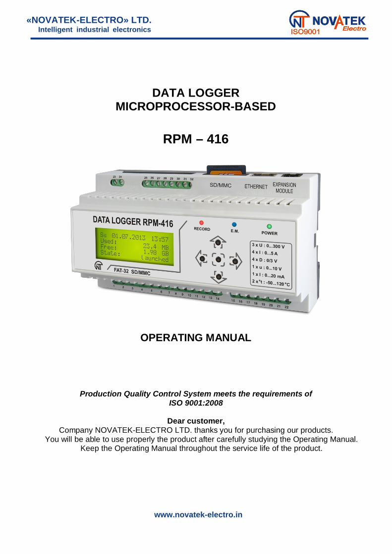
«NOVATEK-ELECTRO» LTD.
DATA LOGGERMICROPROCESSOR-BASED
RPM – 416
OPERATING MANUAL
Production Quality Control System meets the requirements ofISO 9001:2008
Dear customer,Company NOVATEK-ELECTRO LTD. thanks you for purchasing our products.
You will be able to use properly the product after carefully studying the Operating Manual.Keep the Operating Manual throughout the service life of the product.
Intelligent industrial electronics
www.novatek-electro.in
~ 2 ~
RPM-416 NOVATEK-ELECTRO
ATTENTION! ALL REQUIREMENTS OF THIS OPERATION MANUAL ARE COMPULSORY TO BE MET!
WARNING! – PRODUCT TERMINALS AND INTERNAL COMPONENTS ARE UNDER POTENTIALLYLETHAL VOLTAGETO ENSURE THE PRODUCT SAFE OPERATION IT IS STRICTLY FORBIDDEN THE FOLLOWING:
TO CARRY OUT MOUNTING WORKS AND MAINTENANCE WITHOUT DISCONNECTING THEPRODUCT FROM THE MAINS;
- TO OPEN AND REPAIR THE PRODUCT INDEPENDENTLY;TO OPERATE THE PRODUCT WITH MECHANICAL DAMAGES OF THE CASE.
IT IS NOT ALLOWED WATER PENETRATION ON TERMINALS AND INTERNAL ELEMENTS OF THEDEVICE.
During operation and maintenance the regulatory document requirements must be met, namely:Regulations for Operation of Consumer Electrical Installations;Safety Rules for Operation of Consumer Electrical Installations;Occupational Safety when in Operation of Electrical Installations;
Installation, adjustment and maintenance of the product must be performed by qualified personnel havingstudied this Operating Manual.
THE VALUES OF MEASURED SIGNALS CONNECTED TO THE REGISTER INPUT TERMINALS SHOULDNOT EXCEED THOSE SPECIFIED IN THIS MANUAL BECAUSE IT MAY RESULT IN DAMAGE OF INCOMINGLINES, DISRUPTION OF CONTACT GROUP AND REGISTER INFLAMMATION.
The data logger connection, setting and maintenance should be made only by authorized personnel who havestudied this operating manual.
While repair work, maintenance work, installation work it is necessary to disconnect the data logger andincoming measuring lines from the power supply.
The device is safe for operation under observing the rules of exploitation.

~ 3 ~
NOVATEK-ELECTRO RPM-416
CONTENT
1 PURPOSE 5 1.1 Unit’s Purpose 5
1.2 Controls, overall and installation dimensions 61.3 Working conditions 7
2 COMPLETENESS OF SET 73 TECHNICAL SPECIFICATION OF RPM-416 7
3.1 Basic Technical Features 73.2 Inputs characteristics 7
4 DESIGN AND OPERATION PRINCIPLE OF RPM-416 84.1 Design 84.2 Operation principle 94.3 Real time clock 9
5 CONNECTION OF RPM-416 95.1 Preparing for connection 95.2 General instructions Technical maintenance and safety measures 95.3 Connection 95.4 Connection of Expansion modules to RPM-416 105.5 Connection of RPM-416 to Ethernet 11
6 SCOPE OF INTENDED USE 116.1 The use of data logger RPM-416 11
6.1.1 Initialization 5.3 Safety measures 116.1.2 Main screen 5.4 General instruction 116.1.3 Main screen menu items dissimulation 126.1.4 Starting up and finishing of data recording process 126.1.5 Data recording at event 136.1.6 The main menu of the data logger 146.1.7 The review of measured values 156.1.8 Error message conformation 16
6.2 Use of HTTP server (Web-interface) 186.3 Use of Modbus TCP server 186.4 Use of FTP server 326.5 Use of Overvis client 336.6 Inserting and pulling out of the Memory Card 336.7 RPM-416 Data Analysis software installation 336.8 Installation and connection of software for memory card-reader 336.9 Review of the recorded data 34
7 SETTING OF RPM-416 REGISTER 347.1 Setting of Date and Time (“DATE AND TIME”) 34
7.1.1 Setting of Date (“Date”) 347.1.2 Setting of Time (“Time”) 35
7.2 Setting of base channels 357.2.1 Setting of the channel of voltage (1, 2 and 3) 357.2.2 Setting of the channel of current (“Channel 4” (5, 6 and 7)) 367.2.3 Setting of the channel of temperature (“Channel 8” (9)) 367.2.4 Setting of channel of analog voltage 0-10 V (“Channel 10”) 377.2.5 Setting of the channel of analog current 0-20 mA (“Channel 11”) 387.2.6 Setting of the channel of discrete signal (“Channel 12” (13, 14 and 15)) 397.2.7 Setting of the channel of power (“Channel 16” (17 and 18)) 39
7.3 Expansion modules 397.3.1 Turning the power on and off for expansion modules (“On / Off”) 397.3.2 Expansion module (“Module 1” (2, 3 and 4)) setting 40
7.4 Setting of display (“DISPLAY”) 407.4.1 Setting of the display backlight mode (“Backlight settings”) 40
7.5 Setting of record of data mode (“RECORD OF DATA”) 407.5.1 Setting of data recording type (“Record type”) 417.5.2 Setting of recording period (“Recording period”) 417.5.3 Setting of the size of data file (“File size”) 417.5.4 Selection of recorded data (“Choice of data”) 41
7.6 Setting of the mode of data recording at event (“RECORD OF EVENT”) 427.6.1 Switching on and switching off the data recording at event (“On / Off”) 427.6.2 Setting of the time of data recording at event (“Recording time”) 427.6.3 Setting of discreteness of data recording at event (“Discreteness”) 43

~ 4 ~
RPM-416 NOVATEK-ELECTRO
7.6.4 Setting of event (“Event 1” (2, 3, 4 and 5)) 437.7 Setting of memory card (“MEMORY CARD”) 44
7.7.1 Brief information about the memory card (“Information”) 447.7.2 Safety removes of the memory card (“Remove card”) 447.7.3 Formatting of the memory card (“Format”) 45
7.8 Setting of Ethernet network (“NETWORK”) 457.8.1 Setting of Modbus TCP server (“Modbus TCP”) 457.8.2 Setting of HTTP server (“HTTP”) 477.8.3 Setting of FTP server 487.8.4 Overvis Client setting 507.8.5 Setting of main parameters of Ethernet (“TCP / IP”) 51
7.9 Setting of access restriction to the Data Logger (“PASSWORD”) 527.9.1 Switching On and Switching Off of the Password Protection (“On / Off”) 527.9.2 Changing of password value (“Change”) 52
7.10 Reset of all setting to the factory settings (“RESET ALL SETTINGS”) 537.11 Review of software version (“DEVICE VERSION”) 54
8 MAINTENANCE 549 SERVICE LIFE AND MANUFACTURER WARRANTY 5510 TRANSPORTATION AND STORAGE 5511 ACCEPTANCE CERTIFICATE 5512 NOTICES OF CLAIMS 55Appendix A. Connection of Data logger to Ethernet 56Appendix B. Connection of Data logger to Internet 58

~ 5 ~
NOVATEK-ELECTRO RPM-416
This operation manual is intended for description, principle of work, construction, mode of work andmaintenance of the microprocessor-based data logger RPM-416 (further in text as «data logger», «RPM-416» or«data logger RPM-416»).
The product meets the requirements of the following: IEC 60947-1:2004, ; EC 60947-6-2:1992, DT; CISPR 11:2004, IDT; IEC 61000-4-2:2001, IDT.
Harmful substances, in more than allowed concentration, are not available.
Terms and abbreviations:Twisted pair – a pair of isolated signal line wires in cable twisted between themselves for reduction of
transmitted signals distortions;THDr - total harmonic distortion, of a signal is a measurement of the harmonic distortion present and is
defined as the ratio of the sum of the powers of all harmonic components to the power of the fundamentalfrequency. THD is used to characterize the linearity of power quality of electric power systems.
Display – a symbolic LCD display 4 lines of 20 symbols;Cursor – a screen symbol , showing the current position to which the action will be used;Memory card – a portable flash-memory card SD / MMC, which is used for multiple recording and storage
of information in the portable electronic devices;EM – Expansion Module (a device connected to the data logger for Expansion of incoming signals range);MM – Measuring Module (is a part of data logger scheme).PC – Personal Computer;
S – Operating System;On default – preset parameters values which are used by the data logger until the user explicitly changes them;Dry contact – a terminal which has no galvanic connection with power supply lines and "ground” (for
example: mechanical button, hermetic contact, relay contacts, standard and limit switches);CT – Current Transformer intended for transmitting the signal of measuring information (for example:
-0.66, TOP-066, TSHP-0.66 etc. with accuracy class index 0.5 or 0.5 S);Formatting — the process of recording in the memory card file system structure (FAT12, FAT16 or FAT32),
which makes it possible to use the memory card in operational system for data storage;Screen – full-scale (4 lines with 20 symbols) image output on the display;10Base-T – a standard Ethernet for linking up via twisted pairs with speed 10 Mbit/sec;100Base-T – a standard Ethernet for linking up via twisted pairs with speed 100 Mbit/sec;DHCP – network protocol which enables the devices to receive automatically IP-addresses and other
parameters necessary for work in TCP / IP networks;Ethernet – package technology of data transmitting mainly used in computer local networks;FTP – standard protocol of files transmitting in TCP / IP networks;Modbus TCP – open communicational protocol based on “client-server” architecture. It is used for data
transmitting in TCP / IP networks;MAC – address used in transmitting via Ethernet for device identification. As a rule it has a global unique
denotation;RMS –root mean square value;RJ-45 – unified connector used for connection in networks via standard 10Base-T/100Base-T;RJ-11 – unified connector used for connection of telephone or communicational equipment;Web-interface – system of user interaction with device via computer browser.
1 PURPOSE1.1 UNIT’S PURPOSEData logger RPM-416 is a microprocessor-based device intended for electrical parameters measuring and
monitoring on the data logger display as well as data archiving.The data archiving is made on the removable memory card (SD / MMC), which can be later analyzed by
software program RPM-416 Data Analysis (the program can be found on website www.novatek-electro.com),installed on the standard or portable PC. Data files have Expansion “RDF”.
Data logger RPM-416 has an inbuilt real time clock with power from a lithium-type battery.RPM-416 can be connected to Ethernet network via standard 10Base-T or 100Base-T. In this case simultaneously
with data recording to memory card, the RPM-416 configuration and data transmitting to the PC is possible.RPM-416 can connect to the system Overvis (monitoring and remote control www.overvis.com).The main possibilities of the data logger:
Multi-channeling – one data logger is sufficient for all working data receiving from the controlled device;Versatility – the additional modules can be connected to the data logger which makes it possible to
expand the range of incoming signals (voltage, current, temperature, discrete inputs, etc.);Galvanic separation – incoming signals of high voltage and current are galvanic separated from other
inputs which ensures easiness of data logger connection;High fidelity – self-control system and data saving algorithm protect against data loss in case of emergency
situations (power supply failure);

~ 6 ~
RPM-416 NOVATEK-ELECTRO
Servicing convenience – four-lined symbolic display with illuminating enables to adjust the data logger andmonitor its work (the values of recorded incoming signals are shown on the display), the key-board is used forsetting and control of the data logger;
Remote monitoring and configuration – if the data logger is installed in a hard accessible place with Ethernetconnection it can simultaneously with the data recording on the memory card make data transmitting to PC. It enables tomake a remote monitoring of the object. The more detailed analysis can be made on the basis of the data stored on thememory card. Web-interface enables via PC browser to make a remote configuration of the data logger without installingany other additional programs. FTP provides remote access to the memory card to retrieve or delete files.
1.2 CONTROLS, OVERALL AND INSTALLATION DIMENSIONS1.2.1 Overall and installation dimensions
Figure 1.1 – Data logger design with overall and fixing dimensions
1.2.2 ControlsOn the data logger front panel there are located the elements of control (five-button keyboard) and indication
(LED symbolic display), Fig. 1.2. With the help of the key-board are made all the settings of the data logger operationparameters and initiation of incoming signals values recording to the memory card. The current values of the datalogger operation, the values of incoming signals and data logger state information are shown on the display.
1 – Display (yellow-green indication);2 – Button (left) is used for moving the indicator to the left;3 – Button (up) is used for moving the indicator upwards or for increasing parameter value;4 – Button (right) is used for moving the indicator to the right;5 – Button (enter) is used for value entry approval or menu item choice;6 – Button (down) is used for moving the indicator downwards or for decreasing the parameter value;7 – LED indicator RECORDING (light on – when the data recording on the memory card is initiated, light off – whenthe data recording on the memory card is finished, flare up – when the data recording on the memory cardis paused, flickering – when there is at least one error in the data logger operation);8 – LED indicator E.M. (E.M. light on – when at least one expansion module is connected, flickering – when there isdata transmitting between expansion modules, light off – when the expansion modules are not connected);9 – LED indicator POWER (light on – when the power is on, light off – when the power is off).
Figure. 1.2 – The data logger controls

~ 7 ~
NOVATEK-ELECTRO RPM-416
1.3 WORKING CONDITIONSThe data logger RPM-416 is intended for working in the following conditions:
Ambient temperature, from - 20 to +45 º ; Atmospheric pressure from 84 to 106.7 kPa; Relative air humidity (at temperature +25 º ) 30 … 80%.
ATTENTION! The product is not intended for operation in the following conditions:– Significant vibration and shocks;– High humidity;– Aggressive environment with content in the air of acids, alkalis, etc., as well as severe contaminations
(grease, oil, dust, etc.).
2 COMPLETENESS OF SETDelivery set is given in Table 2.1.
Table 2.1 – Delivery SetName Quantity, pcs.
RPM-416 1Connection cable with Ethernet network 1Operating Manual 1Package 1
3 TECHNICAL SPECIFICATION OF RPM-4163.1 BASIC TECHNICAL FEATURESThe basic technical features of RPM-416 are resulted in Table 3.1.
Table 3.1 – Basic technical featuresItem Value
Nominal operating supply voltage ( ), V 230 / 240Performance capacity voltage ( / ), V 24 – 265Power-line frequency, Hz 45 – 65Power consumption (from line ~220 V), W, not more 6.0Power consumption (from power source +24 V), W, not more 2.2Period of data recording to the memory card, sec. 0,001 – 3600External memory storage (memory card, optional) SD / MMCMaximal capacity of external memory card, GB 32Supported file systems of external memory card, FAT 12, 16, 32Minimal size of data file, KB 32Maximal size of data file, MB 512Size of one block of recorded data (20 parameters), byte 88Error of clock run, at temperature 25 º , not more, sec / day 1Connection to Ethernet or PC 10Base-T / 100Base-TModbus TCP yesWeb-interface yesFTP yesThe intent of the device Digital indication devicesNominal working mode continuousProtection class rating (case / terminal block) 40 / IP20Protection class from electric shock IIClimatic version NC3.1 (average and cold zone, indoor)Pollution level IIOvervoltage category IIIsolation nominal voltage, V 450Nominal impulse withstand voltage, kV 2.5Cross-section area of connection terminals, mm² 0.2 – 2.5Terminal screw, N*m 0.4Weight, kg, not more 0.5Overall dimensions, mm 91 157 56.3Assembling is designed on standard DIN-rack 35 mmOrientation, user-defined

~ 8 ~
RPM-416 NOVATEK-ELECTRO
3.2 INPUT CHARACTERISTICSInput characteristics of RPM-416 are resulted in Table 3.2.Measurement error is resulted in ± % of scale value.
Table 3.2 – Inputs characteristicsItem Value
Voltage input 3 channelsVoltage measuring range, V 3 – 450Voltage measuring error (for a sine signal) to 300 V ± 1 %
exceed 300 V ± 1.5%Voltage measuring type RMS / Instant / PeakVoltage frequency measuring range, Hz 25.00 – 70.00Voltage frequency measuring error (for sine signal), Hz ± 0.05THDr measuring range 0 – 100 %THDr measuring error (if the signal level more than 14% of the range) ± 2 %Current input 4 channelsCurrent measuring range, A 0.05 – 10.00Current measuring error (for a sine signal) ± 1.0 %Current measuring type RMS / Instant / PeakCurrent sensor type CT with output 5 ASupported rating values , A 5, 10, 15, 20, 30, 40, 50, 75, 100, 150, 200,
300, 400, 600, 800, 1000, 1500, 2000Current frequency measuring range, Hz 25.00 – 70.00Current frequency measuring error (for sine signal) ± 0.05 %Overload capability 50 A (not often than once a minute), not more, sec 0.3THDr measuring range 0 – 100 %THDr measuring error (if the signal level more than 14% of the range) ± 2 %*Working power input 3 channelsActive power measuring range, W 30 – 200 000 000Reactive power measuring rate, VAr 30 – 200 000 000Gross power measuring range, VA 30 – 200 000 000Power factor measuring range, cos 0.01 – 1.000Power measuring error (for a sine signal) ± 2 %Maximum value of active energy scaler, kW*h 999 999 999Maximum value of reactive energy scaler, kV r*h 999 999 999Temperature input 2 channelsTemperature sensor type PTC1000 / PT1000Temperature measuring range for PTC1000, º from -50.0 to +120.0Temperature measuring range for PT1000, º from -50.0 to +250.0Temperature measuring error ± 1.5 °CVoltage input 0 – 10 V ( ) 1 channelVoltage measuring range, V 0.01 – 10.00Voltage measuring error ± 1.0 %Voltage sensor type 0 – 10 V / 2 – 10 VCurrent input 0 – 20 mA ( ) 1 channelCurrent measuring range, mA 0 – 20Current measuring error ± 1.0 %Current sensor type 0 – 20 mA / 4 – 20 mADigital input 4 channelsMeasuring range closed – openedDigital signal sensor type Dry contactPulse frequency measurement range, Pulse * min 1 – 29000Maximum value of pulse scaler 999999999----------* - power input has no physical connection terminals, the power parameters are calculated on basis of measuredvalues of voltage and current.
4. DESIGN AND OPERATION PRINCIPLE OF RPM-4164.1 DESIGNThe data logger is constructively made in plastic case intended for fixing on DIN-rack 35 mm, case dimensions (91
157 57 mm) 9 modules of S type. The case is made of crashworthy, self-extinguishing material.

~ 9 ~
NOVATEK-ELECTRO RPM-416
4.2 OPERATION PRINCIPLEThe data logger operation principle is based on the measuring values from all sensors connected to the data
logger inputs, accumulating the data in the data logger internal memory and data recording to the external memorystorage – memory card (SD / MMC).
4.3 REAL TIME CLOCKThe data logger is equipped with the inbuilt real time clock which is powered (in case of main power failure)
from inbuilt backup power cell – lithium type battery. The power from the backup supply is sufficient continuousoperation of real time clock during 10 years (at temperature 25 º ). In case of data logger operation at temperatureson the limits of working range the working period of clock decreases.
5 CONNECTION OF RPM-4165.1PREPARING FOR CONNECTION: Unpacking the unit (we recommend to save the original package throughout the guarantee life period of the unit); Ensure that unit has no damages after transportation, in case of such refer to supplier or maker; Check the completeness of set (i. 2), in case of non-completeness refer to supplier or maker; Study User’s Manual carefully (special attention should be paid to power supply connection diagram of
the unit); If there are issues concerning unit’s installation, please, refer to maker by phone, indicated in the end of this
Manual.
5.2 GENERAL INSTRUCTIONSIf the temperature of the product after transportation or storage differs from the environment temperature at
which it is expected to operate, then before connection to electric mains keep the product under the operatingconditions within two hours (because the product elements may have moisture condensation).
ATTENTION! ALL CONNECTIONS MUST BE PERFORMED WHEN THE PRODUCT IS DE-ENERGIZED.Error when performing the installation works may damage the product and connected devices.To ensure the reliability of the electrical connections one should use flexible (stranded) wires with insulation for
a voltage not less than 450 V. Recommended cable cross-section to measure current is within 1,5 – 2,5 mm², forthe rest of connections it is within 0,75 – 2,5 mm². The wire ends should be cleared from insulation for 5±0,5 mmand clamped by a sleeve lug. Fixation of wires should exclude mechanical damages, twisting and abrasion ofwires’ insulation
IT IS NOT ALLOWED TO LEAVE EXPOSED PORTIONS OF WIRE PROTRUDING BEYOND THEREMOVABLE TERMINAL BLOCK.
For reliable contact it is necessary to perform tightening of screws of removable terminal block withthe force specified in Table 3.1.
When reducing the tightening torque, the junction point is heated, terminal block may be melted and wire caneburn. If you increase the tightening torque, it is possible to have thread failure of terminal block screws or thecompression of the connected wires.
For reduction of electric field influence the installation of “data logger-sensor” lines should be made as aseparate route (or several routes). The routes should be located separately from the power cables as well as awayfrom the cables which make high frequency and impulse noise. The routes should be planned in such a way thatthe length of signal lines is minimal.
The connection of expansion modules is made with the help of cable CEM-11-1 (see Item 5.4, the cable issupplied along with every expansion module).
The connection of the data logger to Ethernet network is carried out by the cable made according to thestandard ANSI EIA TIA 568B (see Item 5.5, the cable is supply along with the data logger).
During use of backup power supply the connection is made to the same terminals as the main power source. Itis necessary to have a scheme ABI (Automatic Backup Input) for switching from the main power source to thebackup power supply.
For ensuring the continuous data recording ABI should switch power supply to backup source within period notmore than 0.5 sec.
To improve operational properties of the product it is recommended to install the fuse (fuse element), orthe equivalent for current of 3.15 A in power supply circuit for RPM-416.
5.3 CONNECTIONThe connection of RPM-416 is made according to the scheme resulted in picture 5.1.In order to improve safety in the power circuit logger is recommended to install a fuse nominal value of 3.15 A.
NOTE: TERMINALS (23, 24) FOR CONNECTION TO POWER SUPPLY ARE DESIGNED FOR THEMAXIMUM VOLTAGE OF 300 V, AND TERMINAL FOR VOLTAGE MEASUREMENT (1, 2, 3, 4, 5, 6) AREDESIGNED FOR THE MAXIMUM VOLTAGE OF 450 V. TO AVOID THE ELECTRICAL INSULATIONBREAKDOWN, DO NOT CONNECT THE VOLTAGE SOURCES EXCEEDING THE SPECIFIED VALUES.

~ 10 ~
RPM-416 NOVATEK-ELECTRO
FU1 - The fuse (circuit breaker) for current 3.15
Figure 5.1 – Connection diagram of RPM-416
5.4 CONNECTION OF EXPANSION MODULES TO RPM-416Up to 4 expansion modules can be connected to the data logger at the same time. At attempt to add more than
specified quantity of modules the data logger stop to perceive all modules and switches them off.The expansion modules installation should be carried out with the data logger power being switched off.The module connection should be made with cable CEM-11-1 (is not supplied with the data logger).The number indication of cable CEM-11-1 terminals is resulted in the picture 5.2.
Figure 5.2 – Number indication of cable CEM-11-1
One end of the cable is connected to the socket RJ11 located in the data logger as shown in picture 5.1, theother end of the cable is connected to the socket RJ11 located in the expansion module.
The connection linkage is made automatically after power input to the data logger.The cable CEM-11-1 is supplied with every expansion module.
THE CONNECTION OF EXPANSION MODULES SHOULD BE MADE ON THE RIGHT SIDE OFREGISTER CASE AND ONLY VIA CABLE CEM-11-1 (See. Fig. 5.1).

~ 11 ~
NOVATEK-ELECTRO RPM-416
5.5 CONNECTION OF RPM-416 TO ETHERNET NETWORKConnection of the data logger to Ethernet network is carried out via the cable made according to the standard
ANSI EIA TIA 568B category Cat.3 and higher (supplied with the device).The numeral indication of such cable is shown in the picture 5.3.
Figure 5.3 – Numeral indication of cable for connection to Ethernet
One end of the cable is connected to the socket RJ45 located in the data logger as shown in the picture 5.1,the other end of the cable is connected to the socket of network adapter located in the PC or other network device.
LED indicators, located near the socket RJ45. indicate:green – data interchange;yellow – communication.
For communication connection via Ethernet interface the data logger and PC should be in the same IP-sub net.Programming of the data logger while connection to Ethernet network is described in Appendix .Programming of the data logger while connection to Internet network is described in Appendix B.
6 SCOPE OF INTENDED USE6.1 THE USE OF DATA LOGGER RPM-4166.1.1 InitializationAfter supply of the power to the data logger the process of initialization takes place, the LED indicator POWER
(Fig. 1.2 item 9) and on the display (Fig. 3.2 item 1) there is a printed message shown in the picture 6.1.
Figure 6.1 –Initialization of Data logger
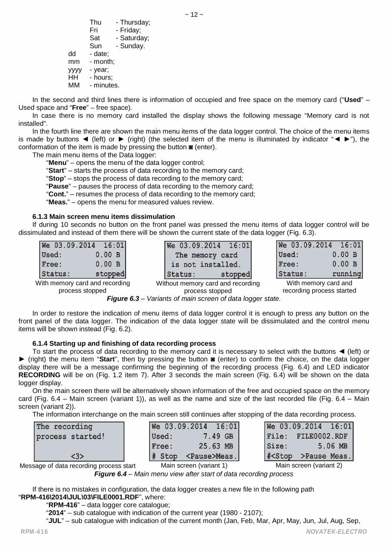
6.1.2 Main screenAfter completion of initialization, the main screen will be shown on the display which view depends on if a
memory card is installed or is not installed. In the figure 6.2 both variants of main screen views are shown.
With memory card Without memory cardFigure 6.2 – Main screen view (with and without memory card)
In the first line there is shown the current date and time in form of DD dd mm yyyy HH:MM, where:DD - day of week:
Mon - Monday;Tue - Tuesday;Wed - Wednesday;
~ 12 ~
RPM-416 NOVATEK-ELECTRO
Thu - Thursday;Fri - Friday;Sat - Saturday;Sun - Sunday.
dd - date;mm - month;yyyy - year;HH - hours;MM - minutes.
In the second and third lines there is information of occupied and free space on the memory card (“Used” –Used space and “Free” – free space).
In case there is no memory card installed the display shows the following message “Memory card is notinstalled”.
In the fourth line there are shown the main menu items of the data logger control. The choice of the menu itemsis made by buttons (left) or (right) (the selected item of the menu is illuminated by indicator “ ”), theconformation of the item is made by pressing the button (enter).
The main menu items of the Data logger:“Menu” – opens the menu of the data logger control;“Start” – starts the process of data recording to the memory card;“Stop” – stops the process of data recording to the memory card;“Pause” – pauses the process of data recording to the memory card;“Cont.” – resumes the process of data recording to the memory card;“Meas.” – opens the menu for measured values review.
6.1.3 Main screen menu items dissimulationIf during 10 seconds no button on the front panel was pressed the menu items of data logger control will be
dissimulated and instead of them there will be shown the current state of the data logger (Fig. 6.3).
With memory card and recordingprocess stopped
Without memory card and recordingprocess stopped
With memory card andrecording process started
Figure 6.3 – Variants of main screen of data logger state.
In order to restore the indication of menu items of data logger control it is enough to press any button on thefront panel of the data logger. The indication of the data logger state will be dissimulated and the control menuitems will be shown instead (Fig. 6.2).
6.1.4 Starting up and finishing of data recording processTo start the process of data recording to the memory card it is necessary to select with the buttons (left) or
(right) the menu item “Start”, then by pressing the button (enter) to confirm the choice, on the data loggerdisplay there will be a message confirming the beginning of the recording process (Fig. 6.4) and LED indicatorRECORDING will be on (Fig. 1.2 item 7). After 3 seconds the main screen (Fig. 6.4) will be shown on the datalogger display.
On the main screen there will be alternatively shown information of the free and occupied space on the memorycard (Fig. 6.4 – Main screen (variant 1)), as well as the name and size of the last recorded file (Fig. 6.4 – Mainscreen (variant 2)).
The information interchange on the main screen still continues after stopping of the data recording process.
Message of data recording process start Main screen (variant 1) Main screen (variant 2)Figure 6.4 – Main menu view after start of data recording process
If there is no mistakes in configuration, the data logger creates a new file in the following path“RPM-416\2014\JUL\03\FILE0001.RDF”, where:
“RPM-416” – data logger core catalogue;“2014” – sub catalogue with indication of the current year (1980 - 2107);“JUL” – sub catalogue with indication of the current month (Jan, Feb, Mar, Apr, May, Jun, Jul, Aug, Sep,

~ 13 ~
NOVATEK-ELECTRO RPM-416
Oct, Nov, Dec);“03” – sub catalogue with indication of the current date (01 – 31);“FILE0001.RDF” – the file name with extension “RDF” (FILE0001 – FILE9999).
When the file size reaches the user defined limit (32 KB – 512 MB), the data logger automatically creates anew file with the following name “FILE0002.RDF”. When the file name reaches the maximum (“FILE9999.RDF”),the recording process will be terminated and on the data logger display there will be a message about an errorshown in the figure 6.5. The LED indicator RECORDING (Fig. 1.2, item 7) will start flickering indicating that there isa mistake in the data logger operation.
Figure 6.5 – The message about an error when the file name reaches the limit
For confirming the error it is necessary to press the button (enter) (Fig. 1.2, item 5). The LED indicatorRECORDING (Fig. 1.2, item 7) will start flickering indicating that the recording process is paused.
Depending on selected by user the recorded readings (the maximal number of recorded at the same timereadings is equal to 20), one data block size being recorded to the memory card for 20 readings is 88 bytes.
The stream of recorded data at discretion 1 ms for 20 readings is:88 KB / sec, 5.28 MB / min or 316.8 MB / hour.stream of recorded data at discretion 1 s for 20 readings is:88 byte / sec, 5.28 KB / min or 316.8 KB / hour.In order to stop the recording process it is necessary on the main screen of the data logger (Fig. 6.6) by buttons
(left) or (right) to select a menu item STOP, and by button (enter) to confirm the selection. On the display ofthe data logger there will be a message (Fig. 6.6), in which it is necessary to confirm the stop of the recordingprocess.
Main screen Screen of confirming the recording process stop “Yes” / “No”
Figure 6.6 – View of main screen and screen of confirming the recording process stopFor confirming the recording process stop it is necessary to select by buttons (left) or (right) indicator
position “YES”, and by button (enter) confirm the selection, the data logger will stop the recording process of datato the memory card the LED indicator RECORDING (Fig. 1.2, item 7) will light off and the display will look as shownin the figure 6.2 (with memory card).
After locating the indicator in position “NO”, the data logger will continue recording and there will be on thedisplay the main screen resulted in the figure 6.6.
If during the recording the memory card is full and has no free space, then depending on the selected type ofrecording (“Until memory” or “The ring”):“Until memory” – there will be a message about an error on the display (resulted in the figure 6.7), and the
recording automatically stops.
Figure 6.7 – A message about an error when there is no free space on thememory card
“The ring” – there will be a message on the display about the deleting of old files (resulted in the figure 6.8).The data logger makes searching and deleting the old files in order to free some space on thememory card for creating a new file.
Figure 6.8 – A screen of old files deleting
During old files deleting the data recording to the memory card pause and after freeing the availablespace for a new file, the recording starts automatically.
6.1.5 Data recording at eventRPM-416 can make data recording at event (this mode is described in the chapter 7, item 7.6).

~ 14 ~
RPM-416 NOVATEK-ELECTRO
If the data recording at event is switched on, the values measured by the data logger continuously are beingrecorded in temporary buffer storage with a user defined periodic sequence (parameter “Discreteness” at default is1 ms). Maximal length of temporary buffer storage is 1480 recordings.
The buffer storage is a sequential date, where the reading is performed from “beginning”, and recording ismade to “end”. When the buffer is full the data deleting is performed from “beginning”, and the new data is beinglocated in “end”.
In RPM-416 there are available five sources of events, every of which can be set individually to any of the datalogger inputs.
Until the event happens, the data logger continuously checks the measured values with the up and down limitsspecified by the user during the event setting. If the measured value is higher (up limit) or lower (down limit) theevent is generated.
After the event happens, the data recording is performed in three stages, as resulted in figure 6.9.
Figure 6.9 – Data recording at event (stages)
At the first stage, the values accumulated in the temporal buffer storage are recorded.At the second stage the value generated the event is recorded.At the third stage after event changed values are recorded.After completion of all stages of recording the data logger goes to stand-by mode waiting for a new event.The number of values recorded before and after the event is set by parameters “Points before” and “Points
after” in the menu of events setting (Chapter 7, item 7.6.2).If the limit of the event is set for a single recording (“ONCE” Chapter 7, item 7.6.4.2), then there will be no
generating of the next event if the measured value is lower (up level) or higher (down level) of specified limits.If the event limit is set on continuous recording (“LONG” Chapter 7, item 7.6.4.2), then after the event happens the
data recording will continue, until the measured value is higher (up level) or lower (down level) of specified limits.
6.1.6 The main menu of the data loggerFor entering in the data logger main menu it is necessary: on the main screen by buttons (left) or (right) to
select item “MENU/ ”, and by button (enter) to confirm the selection. If the password was set before thedata logger asks to enter the password (Fig. 6.10 Screen of password entering).
Screen of password entering Message about an error of password entering
Fig. 6.10 – Screen of password entering and screen of an error of password entering
The password entering is carried out in the following manner: by buttons (left), (right), (up) and (down) make the selection of one digit of password (the selected digit is illuminated by cursor), and by button (enter) confirm the selection.
Sign “^” indicates the digit which is selected at the moment.To delete one digit of the password it is necessary to set a cursor in position “c” (for example in case of error
selection).After completion of password selection it is necessary to set a cursor in position “ ” and press the button (enter),
if the password is not correct there will be a message about the mistake on the display resulted in the figure 6.10.If the password is correct or if the password was deactivated by the user, there will be a list of main menu
available items on the display of the data logger.The screen of the data logger main menu is resulted in the figure 6.11.
Figure 6.11 – Screen of the data logger main menu
The selection of the menu items is made by buttons (up) or (down), the confirmation of the selection is

~ 15 ~
NOVATEK-ELECTRO RPM-416
made by button (enter).To escape from the main menu it is necessary to press the button (left). If there were made changes in
settings, the data logger asks to save them by the message on the display resulted in figure 6.12. Otherwise on thedata logger display there will be the main screen (Fig. 6.2).
Figure 6.12 – Screen of saving the changes
To confirm the saving it is necessary by button (left) locate the cursor in position “YES” and press the button (enter). The data logger makes saving of the settings in nonvolatile memory and the display will show the main
menu (Fig. 6.2).To cancel the saving of the settings it is necessary by button (right) to put the cursor in position “NO” and
press the button (enter). The data logger will load the settings from the nonvolatile memory and the display willshow the main menu (Fig. 6.2).
The full list of items of the main menu is described Chapter 7 “The setting of the data logger RPM-416”.
The item “MENU” of the main screen (Fig. 6.2) is available when the data recording to the memory card isstopped. To stop the recording process it is necessary to follow the procedure described in item 6.1.4.
6.1.7 The review of measured valuesTo review the measured values it is necessary: on the main screen by buttons (left) or (right) to select
item “Measuring”, and by the button (enter) confirm the selection. The display shows the first of a list of availablechannels and the measured values.
The screen of measured values for channel 1 is resulted in figure 6.13.
Figure 6.13 – Screen of measured values for channel 1
The first three lines are displayed measured values available for this channel.The fourth line displays the menu item "BACK" navigation direction symbols and channel number ("CH01").Shifting to the next open channel is made by pressing the button (left) or (right), and by buttons (up) or
(down) you can scroll through the list of available measuring.To escape from the screen of measured values it is necessary to press the button (enter), the display will go
to initial view (Fig. 6.4 – Main screen).In the table 6.1 there is a list of channels with corresponding names of measured values.
Table 6.1 – The list of channels with corresponding names of measured values
Ch. Number values1 2 3 4 5 6
1 Voltage RMS, V Frequency, Hz THDr, % Peak +voltage, V
Peak -voltage, V
Instantaneousvoltage, V
2 Voltage RMS, V Frequency, Hz THDr, % Peak +voltage, V
Peak -voltage, V
Instantaneousvoltage, V
3 Voltage RMS, V Frequency, Hz THDr, % Peak +voltage, V
Peak -voltage, V
Instantaneousvoltage, V
4 Current RMS, A Frequency, Hz THDr, % Peak +current, A
Peak –current, A
Instantaneouscurrent, A
5 Current RMS, A Frequency, Hz THDr, % Peak +current, A
Peak -current, A
Instantaneouscurrent, A
6 Current RMS, A Frequency, Hz THDr, % Peak +current, A
Peak -current, A
Instantaneouscurrent, A
7 Current RMS, A Frequency, Hz THDr, % Peak +current, A
Peak -current, A
Instantaneouscurrent, A
8 Temperature, º ----- ----- ----- ----- -----9 Temperature, º ----- ----- ----- ----- -----
10 Analog voltage, V User’s Value ----- ----- ----- -----11 Analog current, mA User’s Value ----- ----- ----- -----
12 Digitalinput
Frequency,Pulse*min Pulse Scaler ----- ----- -----

~ 16 ~
RPM-416 NOVATEK-ELECTRO
Table 6.1 (continued)
Ch. Number values1 2 3 4 5 6
13 DigitalInput
Frequency,Pulse*min Pulse Scaler ----- ----- -----
14 DigitalInput
Frequency,Pulse*min Pulse Scaler ----- ----- -----
15 Digitalinput
Frequency,Pulse*min Pulse Scaler ----- ----- -----
16 Activepower, W
Reactivepower, var
Fullpower, VA
Powerfactor, cos
Active EnergyScaler, kW*h
Reactive EnergyScaler, kVAr*h
17 Activepower, W
Reactivepower, var
Fullpower, VA
Powerfactor, cos
Active EnergyScaler, kW*h
Reactive EnergyScaler, kVAr*h
18 Activepower, W
Reactivepower, var
Fullpower, VA
Powerfactor, cos
Active EnergyScaler, kW*h
Reactive EnergyScaler, kVAr*h
19 Line voltageAB, V
Line voltageBC, V
Line voltageCA, V
Negative sequ-ence voltage, V
Positive sequ-ence voltage, V
Zero sequencevoltage, V
20-40 The names of the measured values depends on the connected expansion modules-------Channels 16, 17, 18 and 19 do not have a physical connection of the terminals, their values are calculated from themeasured values of the respective current and voltage: - Channel16 = Channel 1 and Channel 4; - Channel17 = Channel 2 and Channel 5; - Channel18 = Channel 3 and Channel 6; - Channel19 = Channel 1, Channel 2 and Channel 3
6.1.8 Error message confirmationIn the process of the data logger work there can happen different errors (real time clock error, data exchange
failure, settings failure etc.).The total list of possible errors is presented in Table 6.2.If an error takes place it is shown on the display of the data logger. The LED indicator RECORD begins to blink.The error message will be on the display until all errors are confirmed.Screen with an error message is resulted in the figure 6.14.
Figure 6.14 – Screen with an error message
In the first line there is a description of error and its code “ERROR # 6!”. As well in the first line there is acurrent number of error and total quantity of errors “1/ 3”.
In the second, third and fourth lines there is an error text.By buttons (up) and (down) you can scroll the list of errors and by button (enter) you can confirm the
current error.If all the error are confirmed by user but the data logger continues to state the active errors, the LED indicator
RECORD continues to flicker. After 20 seconds the data logger will again show the active errors on the display.If there are no active errors and the user confirmed all the errors, LED indicator RECORD lights off – in case the
recording is stopped, lights on – in case the recording continues or lights flicker – in case the recording is paused.
Table 6.2 – Total list of possible errors of the data logger
Error code Error message Troubleshooting method# 1 Failure is detected real-time clock Set the date and time.# 2 No connection with ADC!
Switch off and switch on again the data logger.# 3 No connection to MM!# 4 No connection with EM!# 5 No connection with ROM!# 6 No disc is in the memory card slot! Insert the memory card in slot of the data logger.# 7 Disk is write protected! Deactivate the recording protection on the memory card.# 8 Unable to initialize the disk! Switch off and switch on again the data logger.
Take out and insert the memory card in the data logger.Replace the memory card.# 9 Unable to connect to the disk!

~ 17 ~
NOVATEK-ELECTRO RPM-416
Error code Error message Troubleshooting method
#10 Memory card is full!Delete the files which are not used on the memory card.Use recording mode “Circling”.Replace the memory card.
#11 Unable to read data from the disk! Switch off and switch on again the data logger.Take out and insert the memory card in the data logger.Format the memory card.Replace the memory card.
#12 Unable to create oropen a directory RDF!
#13 Limit exceeded (9999), the filename!
Delete the file from current directory.Replace the memory card.
#14 Unable to get thelist of files!
Switch off and switch on again the data logger.Take out and insert the memory card in the data logger.Format the memory card.Replace the memory card.
#15 Can not create file!#16 Unable to write to file!
#17 Damaged settings in the flashmemory!
Reset the settings of the data logger to factory settings.Reset the data logger.
#18 Unable to save settings to flashmemory!
Switch off and switch on again the data logger.Reset the data logger.
#19 Damage the calibrationin flash memory!
The data logger should be calibrated.This procedure can be performed only at themanufacturer plant.
#20 Memory overflow Switch off and switch on again the data logger.
#21 - #32 Unknown error! The reserved errors codes.Switch off and switch on again the data logger.
--- NMI_HANDLER
Critical error.Switch off and switch on again the data logger.
--- HARDFAULT_HANDLER--- MEMMANAGE_HANDLER--- BUSFAULT_HANDLER--- USAGEFAULT_HANDLER--- STACK_OVERFLOW--- LCD_Init--- SETTINGS_Init--- TIM2_Config--- ETH_Config--- SPI1_Config--- SPI3_Config
Critical error.Switch off and switch on again the data logger.
--- ADC1_Config--- USART2_Config--- NVIC_Config--- BUTTON_Init--- DIGINP_Init--- SD_Init--- SRAM_Init--- RTC_Init--- ADCM_Init--- USART2_Init--- Modules_Init
Critical error.Switch off and switch on again the data logger.
--- TCPStack_Init--- OVERVIS_Init--- HTTP_Init--- MODBUS_Init--- FTP_Init--- TWRITE_Create--- TCOLL_Create--- TGUI_Create--- TGKeep_Create
6.2 USE OF HTTP SERVER (WEB-INTERFACE)For access to Web-interface of the data logger, the PC is required with installed Web-browser.In the Web-browser put in IP-address of the data logger (factory setting 192.168.0.2) and press the button of
access to this address.On the PC screen there will be a welcome page of the data logger RPM-416 with offer to enter the password

~ 18 ~
RPM-416 NOVATEK-ELECTRO
(factory setting “admin”).After the password entering and pressing of the button “Enter”, if the password is correct, there will be the main
screen of the data logger. If the password is not correct, there will be a password error message on the PC display.On the main screen you can monitor the current state of the data logger, make setting, control and restart.After resetting RPM-416 it is necessary to press the button ”Save setting”. The entered settings will be
checked. In case there are no errors in the setting parameters, they will be saved in nonvolatile memory of the datalogger. In case there are some errors in the setting parameters they will not be saved.
After the completion of the work with Web-interface it is necessary to press the button “Exit”, the main page willbe closed and the welcome and password page will be opened.
If there is no activity of the user during 5 minutes (this period is specified by the user, see item 7.8.2.3), the datalogger automatically closes the communication. In this case it is necessary to enter IP-address of the data logger andpassword again.
Note – if the address parameters in Ethernet network (MAC-address, IP-address or DHCP setting) were changedthen in response to pressing the button “Restart”, Web-browser may not load the page. It happens because Web-browser requests to the old address of the data logger. In this case it is necessary to restart the connection.
The data logger has restriction of number of simultaneously connected clients to Web-interface (not morethan Five). All connections exceeding the limit will be automatically closed.
6.3 USE OF MODBUS TCP SERVERConnection protocol Modbus TCP enables to connect the data logger to the network organized by standard
Ethernet. The use of the data logger in network enables to perform the following operations: data receiving in systems SCADA; programming the data logger via PC (by program RPM-416 Data Analysis); remote control of the data logger.
While connection to the data logger, the access to the command registry and recording function is blocked(reading function is not blocked). To unblock the access to the command data logger and recording function it isnecessary to write in registries 51-63 modbus password in symbols ASCII (factory variant “admin”). In not usedregistries there should be written zero values (0x0000).
In case if the modbus password is correct, the data logger will unlock the access to the command registry andrecording function.
The data logger control is carried out via the command registry (Table 6.5).After completing of data logger resetting, it is necessary to carry out the command of recording in the
nonvolatile memory (0x472C). For the changes to take place the data logger should be restarted (0xF2C5).If the functions of recording and register of commands is not used for a long period of time it is necessary to block
the access to them by writing in registries 51-63 the values differing from password modbus (for example, 0).If there is no data exchange for 60 seconds (time is set by the user, item 7.8.1.3), the data logger automatically
breaks the connection with the client.In the data logger al values with a dot are resulted to the whole numbers. That’s why while processing the data
it is necessary to use the additional mathematic operations.To the request of reading the value with a dot (for example, 1.000) the data logger will return the whole number
value 1000, for adjusting to the correct format it is necessary to divide the number by 1000.Before recording the value with a dot (for example, 1.000) it is necessary to bring the value to the whole
number by multiplying by 1000, then make recording of the value in the data logger.The coefficient of changing to whole number is defined by number of digits after the dot (1.0 – 10; 1.00 – 100;
1.000 - 1000).The types of parameters and their names are given in Table 6.3.The list of supported functions (Modbus) is resulted in the Table 6.4.The address of command registry is resulted in Table 6.5.Addresses of additional registries are resulted in Table 6.6.Addresses of the registers of the measured parameters of the base channels are given in Table 6.7.Register addresses parameters measured expansion modules are shown in Table 6.8.Addresses of registries of programmable parameters are resulted in Table 6.9.
The data logger has restriction of number of simultaneously connected clients to Modbus TCP (not morethan five). All connections exceeding the limit will be automatically closed.
Table 6.3 – Types of parameters and their namesType Name Unit of measurement Resolution
0 Unknown (parameter not use) --- ---1 Voltage RMS V 0.12 Voltage Instantaneous V 0.13 Peak + voltage (positive half wave) V 0.14 Peak – voltage (negative half wave) V 0.1

~ 19 ~
NOVATEK-ELECTRO RPM-416
Type Name Unit of measurement Resolution5 Current RMS A 0.016 Current Instantaneous A 0.017 Peak + current (positive half wave) A 0.018 Peak – current (negative half wave) A 0.019 Frequency Hz 0.01
10 THDr % 111 Temperature ºC 0.112 Analog voltage 0-10 V V 0.0113 Analog current 0-20 mA mA 0.0114 Digital input (ON / OFF) --- 115 Full power VA 0.116 Active power W 0.117 Reactive power Var 0.118 Power factor (cos ) --- 0.00119 Active Energy Scaler kW*h 0.120 Reactive Energy Scaler kVAr*h 0.121 User’s Value --- 0.122 Pulse Frequency Pulse*min 0.123 Pulse Scaler --- 124 Line voltage AB V 0,125 Line voltage BC V 0,126 Line voltage CA V 0,127 Negative sequence voltage V 0,128 Positive sequence voltage V 0,129 Zero sequence voltage V 0,1
Table 6.4 – List of supported functionsFunction (hex) Purpose Remark
0x03 Reading of one or several registries Maximum 1250x06 Recording of one values in the register ----0x10 Recording of one or several values in the registries Maximum 123
Table 6.5 – Command registry RPM-416
Name Description WR/RD Address(DEC)
Command registry
Command codes:0xF2C5 – the data logger restart.0x77A6 – to start the recording.0x5606 – to stop the recording.0x5596 – All errors reset.0x472C – to record the settings in nonvolatile memory.0xD357 – to load the settings from nonvolatile memory.0x3010 – energy scalers reset (phase 1, channel 16);0x3011 – energy scalers reset (phase 2, channel 17);0x3012 – energy scalers reset (phase 3, channel 18);0x3020 – pulse scalers reset (channel 12);0x3021 – pulse scalers reset (channel 13);0x3022 – pulse scalers reset (channel 4);0x3023 – pulse scalers reset (channel 15).
WR 50
Modbus password(13 chars ASCII)
Enter the correct password for access to recording (ondefault – “admin”).Enter any not correct value for non-admission to recordingSupported symbols: A-Z; a-z; 0-9.
WR 51-63
----------WR/RD – access type to registry Recording / Reading.Address view “50” means value 16 bit (UINT).Address view “51-63” means a range of 16 bit values.
~ 20 ~
RPM-416 NOVATEK-ELECTRO
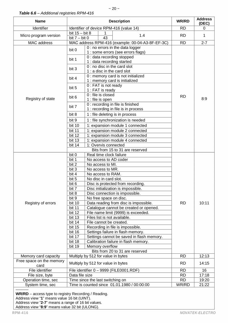
Table 6.6 – Additional registries RPM-416
Name Description WR/RD Address(DEC)
Identifier Identifier of device RPM-416 (value 14) RD 0
Micro program version bit 15 – bit 8 1 1.4 RD 1bit 7 – bit 0 43MAC address address RPM-416 (example: 00-04-A3-8F-EF-3C) RD 2-7
Registry of state
bit 0 0 : no errors in the data logger1 : some errors (see errors flags)
RD 8:9
bit 1 0 : data recording stopped1 : data recording started
bit 3 0 : no disc in the card slot1 : a disc in the card slot
bit 4 0 : memory card is not initialized1 : memory card is initialized
bit 5 0 : FAT is not ready1 : FAT is ready
bit 6 0 : file is closed1 : file is open
bit 7 0 : recording in file is finished1 : recording in file is in process
bit 8 1 : file deleting is in processbit 9 1 : file synchronization is neededbit 10 1: expansion module 1 connectedbit 11 1: expansion module 2 connectedbit 12 1: expansion module 3 connectedbit 13 1: expansion module 4 connectedbit 14 1: Overvis connected
Bits from 15 to 31 are reserved
Registry of errors
bit 0 Real time clock failure
RD 10:11
bit 1 No access to AD coderbit 2 No access to MI.bit 3 No access to MR.bit 4 No access to RAM.bit 5 No disc in card slot.bit 6 Disc is protected from recording.bit 7 Disc initialization is impossible.bit 8 Disc connection is impossible.bit 9 No free space on disc.bit 10 Data reading from disc is impossible.bit 11 Catalogue cannot be created or opened.bit 12 File name limit (9999) is exceeded.bit 13 Files list is not available.bit 14 File cannot be created.bit 15 Recording in file is impossible.bit 16 Settings failure in flash memory.bit 17 Settings cannot be saved in flash memory.bit 18 Calibration failure in flash memory.bit 19 Memory overflow
Bits from 20 to 31 are reservedMemory card capacity Multiply by 512 for value in bytes RD 12:13
Free space on the memorycard Multiply by 512 for value in bytes RD 14:15
File identifier File identifier 0 – 9999 (FILE0001.RDF) RD 16File size, byte Data file size RD 17:18
Operation time, sec Time since the last switching on RD 19:20System time, sec Time is counted since 01.01.1980 / 00:00:00 WR/RD 21:22
----------WR/RD – access type to registry Recording / Reading.Address view “1” means value 16 bit (UINT).Address view “2-7” means a range of 16 bit values.Address view “8:9” means value 32 bit (ULONG).

~ 21 ~
NOVATEK-ELECTRO RPM-416
Table 6.7 – Registers of the measured parameters of the base channels RPM-416
Ch. Value Name Type WR/RD Address(DEC)
1
1 Value type [1] (Voltage RMS L1) UINT RD 100Value ULONG RD 101:102
2 Value type [9] (Voltage frequency L1) UINT RD 103Value ULONG RD 104:105
3 Value type [10] (Voltage THDr L1) UINT RD 106Value ULONG RD 107:108
4 Value type [3] (Peak + voltage L1) UINT RD 109Value ULONG RD 110:111
5 Value type [4] (Peak - voltage L1) UINT RD 112Value ULONG RD 113:114
6 Value type [2] (Instantaneous voltage L1) UINT RD 115Value ULONG RD 116:117
2
1 Value type [1] (Voltage RMS L2) UINT RD 118Value ULONG RD 119:120
2 Value type [9] (Voltage frequency L2) UINT RD 121Value ULONG RD 122:123
3 Value type [10] (Voltage THDr L2) UINT RD 124Value ULONG RD 125:126
4 Value type [3] (Peak + voltage L2) UINT RD 127Value ULONG RD 128:129
5 Value type [4] (Peak - voltage L2) UINT RD 130Value ULONG RD 131:132
6 Value type [2] (Instantaneous voltage L2) UINT RD 133Value ULONG RD 134:135
3
1 Value type [1] (Voltage RMS L3) UINT RD 136Value ULONG RD 137:138
2 Value type [9] (Voltage frequency L3) UINT RD 139Value ULONG RD 140:141
3 Value type [10] (Voltage THDr L3) UINT RD 142Value ULONG RD 143:144
4 Value type [3] (Peak + voltage L3) UINT RD 145Value ULONG RD 146:147
5 Value type [4] (Peak - voltage L3) UINT RD 148Value ULONG RD 149:150
6 Value type [2] (Instantaneous voltage L3) UINT RD 151Value ULONG RD 152:153
4
1 Value type [5] (Current RMS L1) UINT RD 154Value ULONG RD 155:156
2 Value type [9] (Current frequency L1) UINT RD 157Value ULONG RD 158:159
3 Value type [10] (Current THDr L1) UINT RD 160Value ULONG RD 161:162
4 Value type [7] (Peak + current L1) UINT RD 163Value ULONG RD 164:165
5 Value type [8] (Peak - current L1) UINT RD 166Value ULONG RD 167:168
6 Value type [6] (Instantaneous current L1) UINT RD 169Value ULONG RD 170:171
5
1 Value type [5] (Current RMS L2) UINT RD 172Value ULONG RD 173:174
2 Value type [9] (Current frequency L2) UINT RD 175Value ULONG RD 176:177
3 Value type [10] (Current THDr L2) UINT RD 178Value ULONG RD 179:180
4 Value type [7] (Peak + current L2) UINT RD 181Value ULONG RD 182:183
5 Value type [8] (Peak - current L2) UINT RD 184Value ULONG RD 185:186
6 Value type [6] (Instantaneous current L2) UINT RD 187Value ULONG RD 188:189

~ 22 ~
RPM-416 NOVATEK-ELECTRO
Table 6.7 (continued)
Ch. Value Name Type WR/RD Address(DEC)
6
1 Value type [5] (Current RMS L3) UINT RD 190Value ULONG RD 191:192
2 Value type [9] (Current frequency L3) UINT RD 193Value ULONG RD 194:195
3 Value type [10] (Current THDr L3) UINT RD 196Value ULONG RD 197:198
4 Value type [7] (Peak + current L3) UINT RD 199Value ULONG RD 200:201
5 Value type [8] (Peak - current L3) UINT RD 202Value ULONG RD 203:204
6 Value type [6] (Instantaneous current L3) UINT RD 205Value ULONG RD 206:207
7
1 Value type [5] (Current RMS) UINT RD 208Value ULONG RD 209:210
2 Value type [9] (Current frequency) UINT RD 211Value ULONG RD 212:213
3 Value type [10] (Current THDr) UINT RD 214Value ULONG RD 215:216
4 Value type [7] (Peak + current) UINT RD 217Value ULONG RD 218:219
5 Value type [8] (Peak - current) UINT RD 220Value ULONG RD 221:222
6 Value type [6] (Instantaneous current) UINT RD 223Value ULONG RD 224:225
81 Value type [11] (Temperature) UINT RD 226
Value ULONG RD 227:2282 - 6 reserved --- RD 229-243
9 1 Value type [11] (Temperature) UINT RD 244Value ULONG RD 245:246
2 - 6 reserved --- RD 247-261
10
1 Value type [12] (Analog voltage 0-10 V) UINT RD 262Value ULONG RD 263:264
2Value type [21] (User’s Value) UINT RD 265Value ULONG RD 266:267
3 - 6 reserved --- RD 268-279
11
1 Value type [13] (Analog current 0-20 mA) UINT RD 280Value ULONG RD 281:282
2 Value type [21] (User’s Value) UINT RD 283Value ULONG RD 284:285
3 - 6 reserved --- RD 286-297
12
1 Value type [14] (Digital input) UINT RD 298Value ULONG RD 299:300
2 Value type [22] (Pulse frequency) UINT RD 301Value ULONG RD 302:303
3 Value type [23] (Pulse scaler) UINT RD 304Value ULONG RD 305:306
4 - 6 reserved ---- RD 307–315
13
1Value type [14] (Digital input) UINT RD 316Value ULONG RD 317:318
2Value type [22] (Pulse frequency) UINT RD 319Value ULONG RD 320:321
3 Value type [23] (Pulse scaler) UINT RD 322Value ULONG RD 323:324
4- 6 reserved --- RD 325–333

~ 23 ~
NOVATEK-ELECTRO RPM-416
Table 6.7 (continued)
Ch. Value Name Type WR/RD Address(DEC)
14
1 Value type [14] (Digital input) UINT RD 334Value ULONG RD 335:336
2 Value type [22] (Pulse frequency) UINT RD 337Value ULONG RD 338:339
3 Value type [23] (Pulse scaler) UINT RD 340Value ULONG RD 341:342
4 - 6 reserved --- RD 343–351
15
1 Value type [14] (Digital input) UINT RD 352Value ULONG RD 353:354
2 Value type [22] (Pulse frequency) UINT RD 355Value ULONG RD 356:357
3 Value type [23] (Pulse scaler) UINT RD 358Value ULONG RD 359:360
4 - 6 reserved --- RD 361–369
16
1 Value type [15] (Full power L1) UINT RD 370Value ULONG RD 371:372
2 Value type [16] (Active power L1) UINT RD 373Value ULONG RD 374:375
3 Value type [17] (Reactive power L1) UINT RD 376Value ULONG RD 377:378
4 Value type [18] (Power factor (cos ) L1) UINT RD 379Value ULONG RD 380:381
5 Value type [19] (Active Energy Scaler L1) UINT RD 382Value ULONG RD 383:384
6Value type [20] (Reactive Energy Scaler L1) UINT RD 385Value ULONG RD 386:387
17
1 Value type [15] (Full power L2) UINT RD 388Value ULONG RD 389:390
2 Value type [16] (Active power L2) UINT RD 391Value ULONG RD 392:393
3 Value type [17] (Reactive power L2) UINT RD 394Value ULONG RD 395:396
4 Value type [18] (Power factor (cos ) L2) UINT RD 397Value ULONG RD 398:399
5 Value type [19] (Active Energy Scaler L2) UINT RD 400Value ULONG RD 401:402
6 Value type [20] (Reactive Energy Scaler L2) UINT RD 403Value ULONG RD 404:405
18
1 Value type [15] (Full power L3) UINT RD 406Value ULONG RD 407:408
2 Value type [16] (Active power L3) UINT RD 409Value ULONG RD 410:411
3 Value type [17] (Reactive power L3) UINT RD 412Value ULONG RD 413:414
4 Value type [18] (Power factor (cos ) L3) UINT RD 415Value ULONG RD 416:417
5 Value type [19] (Active Energy Scaler L3) UINT RD 418Value ULONG RD 419:420
6 Value type [20] (Reactive Energy Scaler L3) UINT RD 421Value ULONG RD 422:423
19
1 Value type [24] (Line voltage AB ) UINT RD 424Value ULONG RD 425:426
2 Value type [25] (Line voltage BC) UINT RD 427Value ULONG RD 428:429
3 Value type [26] (Line voltage CA) UINT RD 430Value ULONG RD 431:432
4 Value type [27] (Negative sequence) UINT RD 433Value ULONG RD 434:435

~ 24 ~
RPM-416 NOVATEK-ELECTRO
5 Value type [28] (Positive sequence) UINT RD 436Value ULONG RD 437:438
6 Value type [29] (Zero sequence) UINT RD 439Value ULONG RD 440:441
----------The types of parameters are described in Table 6.3.WR/RD – access type to registry Recording / Reading.Address view “100” means value 16 bit (UINT).Address view “106-109” means a range of 16 bit values.Address view “110:111” means value 32 bit (ULONG).
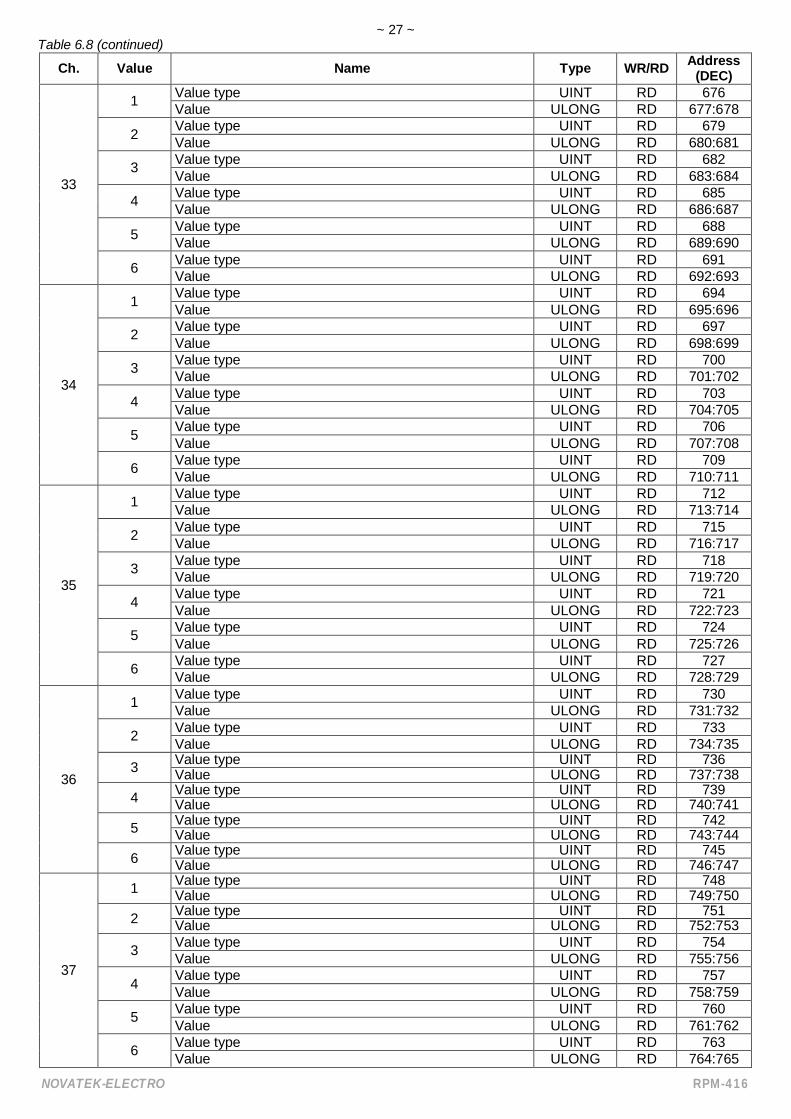
Table 6.8 – Registers of the measured parameters of the expansion modules
Ch. Value Name Type WR/RD Address(DEC)
20
1 Value type UINT RD 442Value ULONG RD 425:426
2 Value type UINT RD 427Value ULONG RD 428:429
3 Value type UINT RD 430Value ULONG RD 431:432
4 Value type UINT RD 433Value ULONG RD 434:435
5 Value type UINT RD 436Value ULONG RD 437:438
6 Value type UINT RD 439Value ULONG RD 440:441
20
1 Value type UINT RD 442Value ULONG RD 443:444
2 Value type UINT RD 445Value ULONG RD 446:447
3 Value type UINT RD 448Value ULONG RD 449:450
4 Value type UINT RD 451Value ULONG RD 452:453
5 Value type UINT RD 454Value ULONG RD 455:456
6 Value type UINT RD 457Value ULONG RD 458:459
21
1 Value type UINT RD 460Value ULONG RD 461:462
2 Value type UINT RD 463Value ULONG RD 464:465
3 Value type UINT RD 466Value ULONG RD 467:468
4 Value type UINT RD 469Value ULONG RD 470:471
5 Value type UINT RD 472Value ULONG RD 473:474
6Value type UINT RD 475Value ULONG RD 476:477
22
1 Value type UINT RD 478Value ULONG RD 479:480
2 Value type UINT RD 481Value ULONG RD 482:483
3 Value type UINT RD 484Value ULONG RD 485:486
4 Value type UINT RD 487Value ULONG RD 488:489
5 Value type UINT RD 490Value ULONG RD 491:492
6Value type UINT RD 493Value ULONG RD 494:495

~ 25 ~
NOVATEK-ELECTRO RPM-416
Table 6.8 (continued)
Ch. Value Name Type WR/RD Address(DEC)
23
1 Value type UINT RD 496Value ULONG RD 497:498
2 Value type UINT RD 499Value ULONG RD 500:501
3 Value type UINT RD 502Value ULONG RD 503:504
4 Value type UINT RD 505Value ULONG RD 506:507
5 Value type UINT RD 508Value ULONG RD 509:510
6 Value type UINT RD 511Value ULONG RD 512:513
24
1 Value type UINT RD 514Value ULONG RD 515:516
2 Value type UINT RD 517Value ULONG RD 518:519
3 Value type UINT RD 520Value ULONG RD 521:522
4 Value type UINT RD 523Value ULONG RD 524:525
5 Value type UINT RD 526Value ULONG RD 527:528
6 Value type UINT RD 529Value ULONG RD 530:531
25
1 Value type UINT RD 532Value ULONG RD 533:534
2 Value type UINT RD 535Value ULONG RD 536:537
3 Value type UINT RD 538Value ULONG RD 539:540
4 Value type UINT RD 541Value ULONG RD 542:543
5 Value type UINT RD 544Value ULONG RD 545:546
6 Value type UINT RD 547Value ULONG RD 548:549
26
1 Value type UINT RD 550Value ULONG RD 551:552
2 Value type UINT RD 553Value ULONG RD 554:555
3 Value type UINT RD 556Value ULONG RD 557:558
4 Value type UINT RD 559Value ULONG RD 560:561
5 Value type UINT RD 562Value ULONG RD 563:564
6 Value type UINT RD 565Value ULONG RD 566:567
27
1 Value type UINT RD 568Value ULONG RD 569:570
2 Value type UINT RD 571Value ULONG RD 572:573
3 Value type UINT RD 574Value ULONG RD 575:576
4 Value type UINT RD 577Value ULONG RD 578:579
5 Value type UINT RD 580Value ULONG RD 581:582
6 Value type UINT RD 583Value ULONG RD 584:585

~ 26 ~
RPM-416 NOVATEK-ELECTRO
Table 6.8 (continued)
Ch. Value Name Type WR/RD Address(DEC)
28
1 Value type UINT RD 586Value ULONG RD 587:588
2 Value type UINT RD 589Value ULONG RD 590:591
3 Value type UINT RD 592Value ULONG RD 593:594
4 Value type UINT RD 595Value ULONG RD 596:597
5 Value type UINT RD 598Value ULONG RD 599:600
6 Value type UINT RD 601Value ULONG RD 602:603
29
1 Value type UINT RD 604Value ULONG RD 605:606
2 Value type UINT RD 607Value ULONG RD 608:609
3 Value type UINT RD 610Value ULONG RD 611:612
4 Value type UINT RD 613Value ULONG RD 614:615
5 Value type UINT RD 616Value ULONG RD 617:618
6 Value type UINT RD 619Value ULONG RD 620:621
30
1 Value type UINT RD 622Value ULONG RD 623:624
2 Value type UINT RD 625Value ULONG RD 626:627
3 Value type UINT RD 628Value ULONG RD 629:630
4 Value type UINT RD 631Value ULONG RD 632:633
5 Value type UINT RD 634Value ULONG RD 635:636
6 Value type UINT RD 637Value ULONG RD 638:639
31
1 Value type UINT RD 640Value ULONG RD 641:642
2 Value type UINT RD 643Value ULONG RD 644:645
3 Value type UINT RD 646Value ULONG RD 647:648
4 Value type UINT RD 649Value ULONG RD 650:651
5 Value type UINT RD 652Value ULONG RD 653:654
6 Value type UINT RD 655Value ULONG RD 656:657
32
1 Value type UINT RD 658Value ULONG RD 659:660
2 Value type UINT RD 661Value ULONG RD 662:663
3 Value type UINT RD 664Value ULONG RD 665:666
4 Value type UINT RD 667Value ULONG RD 668:669
5 Value type UINT RD 670Value ULONG RD 671:672
6 Value type UINT RD 673Value ULONG RD 674:675
~ 27 ~
NOVATEK-ELECTRO RPM-416
Table 6.8 (continued)
Ch. Value Name Type WR/RD Address(DEC)
33
1 Value type UINT RD 676Value ULONG RD 677:678
2 Value type UINT RD 679Value ULONG RD 680:681
3 Value type UINT RD 682Value ULONG RD 683:684
4 Value type UINT RD 685Value ULONG RD 686:687
5 Value type UINT RD 688Value ULONG RD 689:690
6 Value type UINT RD 691Value ULONG RD 692:693
34
1 Value type UINT RD 694Value ULONG RD 695:696
2 Value type UINT RD 697Value ULONG RD 698:699
3 Value type UINT RD 700Value ULONG RD 701:702
4 Value type UINT RD 703Value ULONG RD 704:705
5 Value type UINT RD 706Value ULONG RD 707:708
6 Value type UINT RD 709Value ULONG RD 710:711
35
1 Value type UINT RD 712Value ULONG RD 713:714
2 Value type UINT RD 715Value ULONG RD 716:717
3 Value type UINT RD 718Value ULONG RD 719:720
4 Value type UINT RD 721Value ULONG RD 722:723
5 Value type UINT RD 724Value ULONG RD 725:726
6 Value type UINT RD 727Value ULONG RD 728:729
36
1 Value type UINT RD 730Value ULONG RD 731:732
2 Value type UINT RD 733Value ULONG RD 734:735
3 Value type UINT RD 736Value ULONG RD 737:738
4 Value type UINT RD 739Value ULONG RD 740:741
5 Value type UINT RD 742Value ULONG RD 743:744
6 Value type UINT RD 745Value ULONG RD 746:747
37
1 Value type UINT RD 748Value ULONG RD 749:750
2 Value type UINT RD 751Value ULONG RD 752:753
3 Value type UINT RD 754Value ULONG RD 755:756
4 Value type UINT RD 757Value ULONG RD 758:759
5 Value type UINT RD 760Value ULONG RD 761:762
6 Value type UINT RD 763Value ULONG RD 764:765

~ 28 ~
RPM-416 NOVATEK-ELECTRO
Table 6.8 (continued)
Ch. Value Name Type WR/RD Address(DEC)
38
1 Value type UINT RD 766Value ULONG RD 767:768
2 Value type UINT RD 769Value ULONG RD 770:771
3 Value type UINT RD 772Value ULONG RD 773:774
4 Value type UINT RD 775Value ULONG RD 776:777
5 Value type UINT RD 778Value ULONG RD 779:780
6 Value type UINT RD 781Value ULONG RD 782:783
39
1 Value type UINT RD 784Value ULONG RD 785:786
2 Value type UINT RD 787Value ULONG RD 788:789
3 Value type UINT RD 790Value ULONG RD 791:792
4 Value type UINT RD 793Value ULONG RD 794:795
5 Value type UINT RD 796Value ULONG RD 797:798
6 Value type UINT RD 799Value ULONG RD 800:801
40
1 Value type UINT RD 802Value ULONG RD 803:804
2 Value type UINT RD 805Value ULONG RD 806:807
3 Value type UINT RD 808Value ULONG RD 809:810
4 Value type UINT RD 811Value ULONG RD 812:813
5 Value type UINT RD 814Value ULONG RD 815:816
6 Value type UINT RD 817Value ULONG RD 818:819
----------The types of parameters are described in Table 6.3.WR/RD – access type to registry Recording / Reading.Address view “100” means value 16 bit (UINT).Address view “106-109” means a range of 16 bit values.Address view “110:111” means value 32 bit (ULONG).
Table 6.9 – Programmable parameters RPM-416
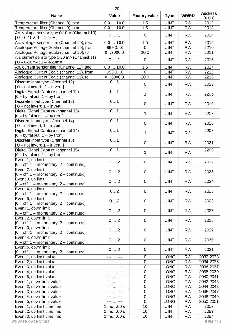
Name Value Factory value Type WR/RD Address(DEC)
Time correction, sec / day -99.9… +99.9 0,0 INT RW 2000Voltage sensor coefficient L1 (Channel 1) 1.0 … 5000.0 1,0 UINT RW 2001Voltage sensor coefficient L2 (Channel 2) 1.0 … 5000.0 1,0 UINT RW 2002Voltage sensor coefficient L3 (Channel 3) 1.0 … 5000.0 1,0 UINT RW 2003Nominal C L1 (Channel 4), 5 … 2000 5 UINT RW 2004Nominal C L2 (Channel 5), 5 … 2000 5 UINT RW 2005Nominal C L3 (Channel 6), 5 … 2000 5 UINT RW 2006Nominal C (Channel 7), 5 … 2000 5 UINT RW 2007Temperature correction (Channel 8), º -9.9 … +9.9 0.0 INT RW 2008Temperature correction (Channel 9), º -9.9 … +9.9 0.0 INT RW 2009Temperature sensor type (Channel 8)[ 0 – PTC1000; 1 – PT1000 ] 0…1 1 UINT RW 2010
Temperature sensor type (Channel 9)[ 0 – PTC1000; 1 – PT1000 ] 0 …1 1 UINT RW 2011
~ 29 ~
NOVATEK-ELECTRO RPM-416
Name Value Factory value Type WR/RD Address(DEC)
Temperature filter (Channel 8), sec 0.0 … 10.0 1.5 UINT RW 2012Temperature filter (Channel 9), sec 0.0 … 10.0 1.5 UINT RW 2013An. voltage sensor type 0-10 V (Channel 10)[ 0 – 0-10V; 1 – 2-10V ] 0 … 1 0 UINT RW 2014
An. voltage sensor filter (Channel 10), sec 0.0 … 10.0 1.5 UINT RW 2015Analogue Voltage Scale (channel 10), from -999.0…0 0 UINT RW 2210Analogue Voltage Scale (channel 10), to 0…3000,0 10.0 UINT RW 2211An. current sensor type 0-20 mA (Channel 11)[ 0 – 0-20mA; 1 – 4-20mA ] 0 … 1 0 UINT RW 2016
An. current sensor filter (Channel 11), sec 0.0 … 10.0 1.5 UINT RW 2017Analogue Current Scale (channel 11), from -999.0…0 0 UINT RW 2212Analogue Current Scale (channel 11), to 0…3000.0 20,0 UINT RW 2213Discrete input type (Channel 12)[ 0 – not invert.; 1 – invert.]
0…1 0 UINT RW 2018
Digital Signal Capture (channel 12)[0 – by fallout; 1 – by front]
0…1 1 UINT RW 2206
Discrete input type (Channel 13)[ 0 – not invert; 1 – invert.]
0…1 0 UINT RW 2019
Digital Signal Capture (channel 13)[0 – by fallout; 1 – by front]
0…1 1 UINT RW 2207
Discrete input type (Channel 14)[ 0 – not invert; 1 – invert.]
0…1 0 UINT RW 2020
Digital Signal Capture (channel 14)[0 – by fallout; 1 – by front]
0…1 1 UINT RW 2208
Discrete input type (Channel 15)[ 0 – not invert; 1 – invert. ]
0…1 0 UINT RW 2021
Digital Signal Capture (channel 15)[0 – by fallout; 1 – by front]
0…1 1 UINT RW 2209
Event 1, up limit[0 – off: 1 – momentary; 2 – continued] 0 … 2 0 UINT RW 2022
Event 2, up limit[0 – off: 1 – momentary; 2 – continued] 0 … 2 0 UINT RW 2023
Event 3, up limit[0 – off: 1 – momentary; 2 – continued] 0 … 2 0 UINT RW 2024
Event 4, up limit[0 – off: 1 – momentary; 2 – continued] 0…2 0 UINT RW 2025
Event 5, up limit[0 – off: 1 – momentary; 2 – continued] 0 …2 0 UINT RW 2026
Event 1, down limit[0 – off: 1 – momentary; 2 – continued] 0 … 2 0 UINT RW 2027
Event 2, down limit[0 – off: 1 – momentary; 2 – continued] 0 … 2 0 UINT RW 2028
Event 3, down limit[0 – off: 1 – momentary; 2 – continued] 0 … 2 0 UINT RW 2029
Event 4, down limit[0 – off: 1 – momentary; 2 – continued] 0 … 2 0 UINT RW 2030
Event 5, down limit[0 – off: 1 – momentary; 2 – continued] 0 … 2 0 UINT RW 2031
Event 1, up limit value --- … --- 0 LONG RW 2032:2033Event 2, up limit value --- … --- 0 LONG RW 2034:2035Event 3, up limit value --- … --- 0 LONG RW 2036:2037Event 4, up limit value --- …--- 0 LONG RW 2038:2039Event 5, up limit value --- … --- 0 LONG RW 2040:2041Event 1, down limit value --- … --- 0 LONG RW 2042:2043Event 2, down limit value --- … --- 0 LONG RW 2044:2045Event 3, down limit value --- … --- 0 LONG RW 2046:2047Event 4, down limit value --- … --- 0 LONG RW 2048:2049Event 5, down limit value --- … --- 0 LONG RW 2050:2051Event 1, up limit time, ms 1 ms…60 s 10 UINT RW 2052Event 2, up limit time, ms 1 ms…60 s 10 UINT RW 2053Event 3, up limit time, ms 1 ms…60 s 10 UINT RW 2054

~ 30 ~
RPM-416 NOVATEK-ELECTRO
Name Value Factory value Type WR/RD Address(DEC)
Event 4, up limit time, ms 1 ms…60 s 10 UINT RW 2055Event 5, up limit time, ms 1 ms…60 s 10 UINT RW 2056Event 1, down limit time, ms 1 ms …60 s 10 UINT RW 2057Event 2, down limit time, ms 1 ms …60 s 10 UINT RW 2058Event 3, down limit time, ms 1 ms…60 s 10 UINT RW 2059Event 4, down limit time, ms 1 ms…60 s 10 UINT RW 2060Event 5, down limit time, ms 1 ms … 60 s 10 UINT RW 2061Event 1, value source[ bit31 – bit24 : channel number; bit23 – bit16 : value number; bit15 – bit0 : value type ]
Ch. 0…17Val. 0…5
Type 0…184294967295 ULONG RW 2062:2063
Event 2, value source[ bit31 – bit24 : channel number; bit23 – bit16 : value number; bit15 – bit0 : value type ]
Ch. 0…17Val. 0…5
Type 0…184294967295 ULONG RW 2064:2065
Event 3, value source[ bit31 – bit24 : channel number; bit23 – bit16 : value number; bit15 – bit0 : value type ]
Ch. 0…17Val. 0…5
Type 0…184294967295 ULONG RW 2066:2067
Event 4, value source[ bit31 – bit24 : channel number; bit23 – bit16 : value number; bit15 – bit0 : value type ]
Ch. 0…17Val. 0…5
Type 0…184294967295 ULONG RW 2068:2069
Event 5, value source[ bit31 – bit24 : channel number; bit23 – bit16 : value number; bit15 – bit0 : value type ]
Ch. 0…17Val. 0…5
Type 0…184294967295 ULONG RW 2070:2071
Display illuminating mode[ 0 – off; 1 – always on;2 – will be off in 30 sec]
0…2 2 UINT RW 2072
Source of data to be written 1[ bit31 – bit24 : channel number; bit23 – bit16 : value number; bit15 – bit0 : value type ]
Ch. 0…17Val. 0…5
Type 0…184294967295 UINT RW 2073:2074
Source of data to be written 2[ bit31 – bit24 : channel number; bit23 – bit16 : value number; bit15 – bit0 : value type ]
Ch. 0…17Val. 0…5
Type 0…184294967295 UINT RW 2075:2076
Source of data to be written 3[ bit31 – bit24 : channel number; bit23 – bit16 : value number;bit15 – bit0 : value type ]
Ch. 0…17Val. 0…5
Type 0…184294967295 UINT RW 2077:2078
Source of data to be written 4[ bit31 – bit24 : channel number; bit23 – bit16 : value number; bit15 – bit0 : value type ]
Ch. 0…17Val. 0…5
Type 0…184294967295 UINT RW 2079:2080
Source of data to be written 5[ bit31 – bit24 : channel number; bit23 – bit16 : value number; bit15 – bit0 : value type ]
Ch. 0…17Val. 0…5
Type 0…184294967295 UINT RW 2081:2082
Source of data to be written 6[ bit31 – bit24 : channel number; bit23 – bit16 : value number; bit15 – bit0 : value type ]
Ch. 0…17Val. 0…5
Type 0…184294967295 UINT RW 2083:2084
Source of data to be written 7[ bit31 – bit24 : channel number; bit23 – bit16 : value number; bit15 – bit0 : value type ]
Ch. 0 …17Val. 0…5
Type 0…184294967295 UINT RW 2085:2086
Source of data to be written 8[ bit31 – bit24 : channel number; bit23 – bit16 : value number; bit15 – bit0 : value type ]
Ch. 0…17Val. 0…5
Type 0…184294967295 UINT RW 2087:2088

~ 31 ~
NOVATEK-ELECTRO RPM-416
Name Value Factory value Type WR/RD Address(DEC)
Source of data to be written 9[ bit31 – bit24 : channel number; bit23 – bit16 : value number;bit15 – bit0 : value type ]
Ch. 0…17Val. 0…5
Type 0…184294967295 UINT RW 2089:2090
Source of data to be written 10[ bit31 – bit24 : channel number; bit23 – bit16 : value number;bit15 – bit0 : value type ]
Ch. 0…17Val. 0…5
Type 0…184294967295 UINT RW 2091:2092
Source of data to be written 11[ bit31 – bit24 : channel number; bit23 – bit16 : value number; bit15 – bit0 : value type ]
Ch. 0…17Val. 0…5
Type 0…184294967295 UINT RW 2093:2094
Source of data to be written 12[ bit31 – bit24 : channel number; bit23 – bit16 : value number; bit15 – bit0 : value type ]
Ch. 0…17Val. 0…5
Type 0…184294967295 UINT RW 2095:2096
Source of data to be written 13[ bit31 – bit24 : channel number; bit23 – bit16 : value number; bit15 – bit0 : value type ]
Ch. 0…17Val. 0…5
Type 0…184294967295 UINT RW 2097:2098
Source of data to be written 14[ bit31 – bit24 : channel number; bit23 – bit16 : value number; bit15 – bit0 : value type ]
Ch. 0…17Val. 0…5
Type 0…184294967295 UINT RW 2099:2100
Source of data to be written 15[ bit31 – bit24 : channel number; bit23 – bit16 : value number; bit15 – bit0 : value type ]
Ch. 0…17Val. 0…5
Type 0…184294967295 UINT RW 2101:2102
Source of data to be written 16[ bit31 – bit24 : channel number; bit23 – bit16 : value number; bit15 – bit0 : value type ]
Ch. 0…17Val. 0…5
Type 0…184294967295 UINT RW 2103:2104
Source of data to be written 17[ bit31 – bit24 : channel number; bit23 – bit16 : value number; bit15 – bit0 : value type ]
Ch. 0…17Val. 0…5
Type 0…184294967295 UINT RW 2105:2106
Source of data to be written 18[ bit31 – bit24 : channel number; bit23 – bit16 : value number; bit15 – bit0 : value type ]
Ch. 0 … 17Val. 0…5
Type 0…184294967295 UINT RW 2107:2108
Source of data to be written 19[ bit31 – bit24 : channel number; bit23 – bit16 : value number; bit15 – bit0 : value type ]
Ch. 0…17Val. 0…5
Type 0…184294967295 UINT RW 2109:2110
Source of data to be written 20[ bit31 – bit24 : channel number; bit23 – bit16 : value number; bit15 – bit0 : value type ]
Ch. 0…17Val. 0…5
Type 0…184294967295 UINT RW 2111:2112
Write period, ms 1 ms…60 m 1000 ULONG RW 2113:2114File size, byte 32 kB…512 MB 32768 ULONG RW 2115:2116Write type[ 0 – until memory; 1 – the ring ] 0…1 0 UINT RW 2117
Write event[ 0 – disabled; 1 – enabled ] 0…1 0 UINT RW 2118
Points before event 0…1920 100 UINT RW 2119Points after event 0 …1920 100 UINT RW 2120Discreteness event writing, ms 1 ms…1000 ms 1 UINT RW 2121Password protection[ 0 – disabled; 1 – enabled ] 0…1 0 UINT RW 2122
Access Password Value (6 symbols of ASCII) A-Z, a-z, 0-9 1234 UINT RW 2123:2128Expansion modules[ 0 – disabled; 1 – enabled ] 0 … 1 0 UINT RW 2129

~ 32 ~
RPM-416 NOVATEK-ELECTRO
Name Value Factory value Type WR/RD Address(DEC)
Type of module 1 0 …1 0 UINT RW 2130Type of module 2 0 …1 0 UINT RW 2131Type of module 3 0 …1 0 UINT RW 2132Type of module 4 0 … 1 0 UINT RW 2133DHCP[ 0 – disabled; 1 – enabled ] 0 …1 0 UINT RW 2134
IP-address --- … --- 192.168.0.2 ULONG RW 2135:2136Mask --- … --- 255.255.255.0 ULONG RW 2137:2138Main Gateway --- … --- 192.168.0.1 ULONG RW 2139:2140Server address DNS 1 --- … --- 192.168.0.1 ULONG RW 2141:2142DNS 2 --- … --- 8.8.8.8 ULONG RW 2143:2144Modbus TCP server[ 0 – disabled; 1 – enabled ] 0 … 1 1 UINT RW 2145
Modbus TCP port 1 … 65535 502 UINT RW 2146Modbus UID 0…255 0 UINT RW 2205Modbus TCP timeout, sec 60 …3600 60 UINT RW 2147MODBUS password (13 chars ASCII) A-Z, a-z, 0-9 “admin” STR RW 2148-2160HTTP server[ 0 – disabled; 1 – enabled ] 0 … 1 1 UINT RW 2164
HTTP port 1 … 65535 80 UINT RW 2165HTTP timeout, sec 60 … 3600 300 UINT RW 2166HTTP password (13 chars ASCII) A-Z, a-z, 0-9 “admin” STR RW 2167-2179FTP server[ 0 – disabled; 1 – enabled ] 0 … 1 0 UINT RW 2183
FTP port 1…65535 21 UINT RW 2184FTP timeout, sec 60…3600 300 UINT RW 2185FTP password (13 chars ASCII) A-Z, a-z, 0-9 “admin” STR RW 2186-2198Overvis client[ 0 – disabled; 1 – enabled ] 0…1 0 UINT RW 2202
Overvis port 1…65535 20502 UINT RW 2203Overvis timeout, sec 60…3600 90 UINT RW 2204----------WR/RD – access type to registry Recording / Reading.Address view “2000” means value 16 bit (UINT).Address view “2140-2155” means a range of 16 bit values.Address view “2028:2029” means value 32 bit (ULONG).
6.4 USE OF FTP SERVERFile transfer protocol FTP uses the double connection. Herein one channel is as a pilot through which the
commands from the data logger come in and respond goes out (on default TCP-port 21), and via the secondchannel comes data communication (TCP-port is defined by the data logger by random choice).
Use of FTP protocol enables via TCP-networks to receive remote files recorded by the data logger on thememory card.
Files’ receiving is carried out with the help of program “RPM-416 Data Analysis” or any other software whichsupport the files receiving via FTP.
In the data logger server FTP operates in passive mode (waiting the client’s connection).At connection to the data logger via FTP it is necessary to write the name of the user “ftp” and password
(factory variant “admin”).Used commands:
ABOR – Abort the file transmitting;CDUP – Change the directory upward;CWD – Change the directory;LIST – Restore the list of current directory files;NLST – Restore the list of current directory files in brief format;NOOP – No operation (is used for timeout reset);PASV – Enter in passive mode and restore address of connection;PWD – Restore the current directory;QUIT – Switch off;RETR – Download the file. Before RETR operation there should be a command PASV;SYST – Return the system type (UINIX);TYPE – Define the type of file transmitting (“I” – binary);

~ 33 ~
NOVATEK-ELECTRO RPM-416
USER – User’s name for input on the server;PASS – Password for the server;STRU – Set file transfer structure. (“F” – file);MODE – Sets the transfer mode (“S” – Stream);REIN – Re-initialize the connection;PORT – Specifies an address and port to which the server should connect;MKD – Make directory;RMD – Remove a directory;STOR – Accept data and store data as a file at the server site;DELE – Delete file.
If there is no data exchange during 300 seconds (time period can be set by the user, item 7.8.3.3), the datalogger automatically breaks the connection with a client.
The data logger has restriction of number of simultaneously connected FTP clients (not more thantwo). All connections exceeding the limit will be automatically closed.
6.5 USE OF OVERVIS CLIENTOvervis is a system for monitoring, visualization and remote control of technological processes.Overvis enables:
to read the data from the instruments, including with the recording system; to perform 24-hour cyclical readout of data; to save the data automatically in its own database; to display the data in the convenient form; to receive alarm reports in the form of SMS or E-Mail.
More detailed information can be found at the official website www.overvis.com.Overvis system acts as a collection server of data from the recording system and other devices connected
simultaneously, and it provides access to data in real time only with the permission of the owner of the recording system.Factory settings of the recording system are prepared to connect to the server of Overvis, in this case the
Overvis client in the recording system is disabled and should be enabled manually by the user.To connect the recording system to the system of Overvis it is required:
to configure the recording system to access the internet; to enable Overvis Client; in the Overvis settings to make sure that there is connection to the server and the activation code is received; using the instructions at Overvis website, to connect to the recording system with the activation code.
Note: When you connect the register to Overvis system for the first time, Overvis activation settings indicatethat connection is activated. To ensure safety one should select RESET item, to remove the unit from Overvissystem. Thus it guarantees, that the register connected is to be used by users possessing rights.
6.6 INSERTING AND PULLING OUT OF THE MEMORY CARDInsert the memory card in the slot situated on the side wall of the data logger, as shown in the figure 5.1 and
press it till there is a click.In order to pull the memory card out, press it till a click and release it – the memory card will go out from the
slot about 3-5 mm, after that you can pull it out.During inserting and pulling out of the memory card do not use much effort.
Do not pull out the memory card during data recording to the data logger – it can result in recordeddata loss. The procedure of safety pulling out of the memory card is described in item 7.7.2.
6.7 RPM-416 DATA ANALYSIS SOFTWARE INSTALLATIONFor proper work of the software on the computer there should be installed Operational System Windows 2000,
Windows XP, Windows Vista or Windows 7. The installation is initiated by starting the installation file“rpm416da_setup.exe” (not included in the supply scope). After starting of the installation, the program performsthe installation guided by the instructions of installation master. If the previous version of the program has beenalready installed on the computer it should be deleted before a new installation.
The latest version of the program is available on the web site http://www.novatek-electro.com in section“Software support”.
To delete the program you should use Windows master of installation and deleting.
NOTE - For Windows Vista / 7/8 Program must be performed with administrator rights.
6.8 INSTALLATION AND CONNECTION OF SOFTWARE FOR MEMORY CARD-READERThe procedure and installation of software for memory cards reading depends on the model and manufacturer
of the device. All installation instructions are resulted in the card reader manual.

~ 34 ~
RPM-416 NOVATEK-ELECTRO
6.9 REVIEW OF THE RECORDED DATAPull out the memory card from the data logger (pulling out of the memory card is described in the item 6.6) and
insert it in the card reader on the PC.Review and analysis of the data is carried out with program software “RPM-416 Data Analysis” installed on the
PC (installation of the software is described in item 6.7).Program “RPM-416 Data Analysis” enables to make the analyses of data, to compare it (in form of numeral
information or diagrams) and output the results of the analysis for printing. The program can also perform a remoteconfiguration of the data logger and monitor its operation in real time mode via protocol Modbus TCP.
7 SETTING OF RPM-416 REGISTERThe description of settings is based on the factory parameters settings.The parameters are saved in the nonvolatile memory (period of storage is not less than 10 years).For restoring the main menu of the data logger it is necessary to perform the actions described in item 6.1.6
“Main menu of the data logger RPM-416”.Total list of main menu items:
“Date and Time” – for setting the date and time;“Base Channels” – for setting the base channels (inputs of the data logger);“Exp. modules” – for setting the expansion modules;“Display” – for setting the display;“Record of data” – for setting the data recording to the memory card;“Record of events” – for setting the events;“Memory card” – for setting the memory card; “Network” – for setting Ethernet interface;“Password” – for setting the access restriction to the data logger;“Reset all settings” – for total reset of all default settings of the data logger;“Device version” – for information about the version of the data logger.
The selection of the menu items is performed by buttons (up) or (down) (the selected item is underlinedby the cursor), confirmation of the selection is made by pressing the button (enter).
For escape from the menu press the button (left).
7.1 SETTING OF THE DATE AND TIME (“DATE AND TIME”)For setting the date and time it is necessary: in the main menu of the data logger by buttons (up) or
(down) select the item “Date and time”, confirm the selection by pressing the button (enter). On the display of thedata logger there will be the list of available menu items for setting the date and time:
“Date” – menu item for setting the date;“Time” – menu item for setting the time.
By buttons (up) or (down) make the selection of the corresponding menu item, confirm the selection bypressing the button (enter).
To restore the previous menu, press the button (left).
7.1.1 Setting of Date (“Date”)At selection of this item on the display of the data logger there will be a screen of the date setting, resulted in
the figure 7.1.1.
Figure 7.1.1 – Screen of date setting
On this screen the date is resulted in format “DDD dd.mm.yyyy”, where:DDD - day of week:
Mo - Monday;Tu - Tuesday;We - Wednesday;Th - Thursday;Fr - Friday;Sa - Saturday;Su - Sunday.
dd - date (from 1 to 31);mm - month (from 1 to 12);yyyy - year (from 1980 to 2107);
By buttons (left), (right), (up) and (down) make a selection of the necessary parameter (the selectedparameter is highlighted by the cursor).
For starting the changes in the parameter it is necessary to press the button (enter), the selected parameter

~ 35 ~
NOVATEK-ELECTRO RPM-416
starts to blink.By buttons (up) or (down) change the value of the parameter. After completion it is necessary to press
again the button (enter) – to escape from the mode of setting and saving of the changed parameter. Theparameter stops blinking.
In case of necessity repeat the same procedure with other parameters.To restore the previous menu it is necessary by button (down) select the position “BACK” and press the
button (enter).
7.1.2 Setting of Time (“Time”)At selection of this item on the display of the data logger there will be a screen of the time setting, resulted in
the figure 7.1.2.
Figure 7.1.2 – Screen of time setting
On this screen the time is resulted in format “HH:MM:SS CC”, where:
HH - hours (from 0 to 23)MM - minutes (from 0 to 59)SS - seconds (from 0 to 59)CC - correction sec / day (from -99,9 to +99,9)
WARNING! Incorrect time correction can leadto a temporary error of up to ± 2 ms persecond during data recording.
By buttons (left), (right), (up) and (down) make a selection of the parameter (the selected parameteris highlighted by the cursor).
For starting the changes in the parameter it is necessary to press the button (enter), the selected parameterstarts to blink.
By buttons (up) or (down) change the value of the parameter. After completion of change it is necessaryto press the button (enter) again – to escape from the mode of setting and saving of the changed parameter. Theparameter stops blinking.
In case of necessity, repeat the same procedure with other parameters.In case of necessity, repeat the same procedure with other parameters.To restore the previous menu it is necessary by button (down) select the position “BACK” and press the
button (enter).
7.2 SETTING OF BASE CHANNELS (“BASE CHANNELS”)The data logger – is a multichannel device, which has different inputs (voltage, current, temperature, discrete
inputs etc.) requiring individual setting.For channels setting it is necessary in the main menu by buttons (up) or (down) select the item
“Channels”, confirm the selection by pressing the button (enter). On the display of the data logger there will bethe list of available channels:
“Channel 1” (2 and 3) – menu items for setting the channels of voltage;“Channel 4” (5, 6 and 7) – menu items for setting the channels of current;“Channel 8” (9) – menu items for setting the channels of temperature;“Channel 10” – menu item for setting the channel of analog voltage 0-10 V;“Channel 11” – menu item for setting the channel of analog current 0-20 mA;“Channel 12” (13, 14 and 15) – menu items for setting the channels of discrete signal;“Channel 16” (17 and 18) – menu items for setting the channels of power.
By buttons (up) or (down) make selection of necessary item of menu, confirm the selection by pressingthe button (enter).
To restore the previous menu, press the button (left).
7.2.1 Setting of the channel of voltage (“Channel 1” (2 and 3))At selection of this item on the display of the data logger there will be a screen with a list of available items for
setting the channel of voltage:“Information” – menu item with a brief information and description; “Voltage sensor” – menu item for setting the coefficient of voltage transfer (with voltage transformers
switched on).By buttons (up) or (down) make a selection of the necessary item, confirm the selection by pressing the
button (enter).To restore the previous menu, press the button (left).
7.2.1.1 Setting of voltage sensor (“Voltage sensor”)At selection of this item on the display of the data logger there will be the screen of setting of voltage

~ 36 ~
RPM-416 NOVATEK-ELECTRO
conversion ratio, resulted in the figure 7.2.1.
Figure 7.2.1 – Screen of setting of voltage conversion ratio
On this screen you can set the voltage conversion ratio from 1.0 to 5000.0.By button (up) select the parameter “1.0” (the selected parameter is highlighted by the cursor).For starting the changes in the parameter it is necessary to press the button (enter), the selected parameter
starts to blink.By buttons (up) or (down) change the value of the parameter. After completion of change it is necessary
to press the button (enter) again – to escape from the mode of setting and saving of the changed parameter. Theparameter stops blinking.
To restore the previous menu it is necessary by button (down) locate the cursor in position “BACK” andpress the button (enter).
7.2.2 Setting of the channel of current (“Channel 4” (5, 6 and 7))At selection of this item on the display of the data logger there will be a screen with a list of available items for
setting the channel of current:“Information” – menu item with a brief description; “Current sensor” – a menu item for setting the current transformer nominal.
By buttons (up) or (down) make a selection of the necessary item of menu, confirm the selection bypressing the button (enter).
To restore the previous menu, press the button (left).
7.2.2.1 Setting of current sensor (“Current sensor”)At selection of this item on the display of the data logger there will be the screen of setting of current
transformer rated, resulted in the figure 7.2.2.
Figure 7.2.2 – Screen of setting of current transformer rated
On this screen you can set the rated of used current transformer from the following row: 5 , 10 , 15 , 20 ,30 , 40 , 50 , 75 , 100 , 150 , 200 , 300 , 400 , 600 , 800 , 1000 , 1500 , 2000 .
By button (up) select the parameter “Rated” (the selected parameter is highlighted by the cursor).For starting the changes in the parameter it is necessary to press the button (enter), the selected parameter
starts to blink.By buttons (up) or (down) change the value of the parameter. After completion of change it is necessary
to press the button (enter) again – to escape from the mode of setting and for saving of the changed parameter.The parameter stops blinking.
To restore the previous menu it is necessary by button (down) locate the cursor in position “BACK” andpress the button (enter).
7.2.3 Setting of the channel of temperature (“Channel 8” (9))At selection of this item on the display of the data logger there will be a screen with a list of available items for
setting the channel of temperature:“Information” – menu item with a brief description; “Temperature sensor” – a menu item for setting the type of sensor and for making correction of thetemperature.
By buttons (up) or (down) make a selection of the necessary item of menu, confirm the selection bypressing the button (enter).
To restore the previous menu, press the button (left).
7.2.3.1 Setting of temperature sensor (“Temperature sensor”)At selection of this item on the display of the data logger there will be a screen of setting of temperature sensor,
resulted in the figure 7.2.3.
Figure 7.2.3 – Screen of temperature sensor setting

~ 37 ~
NOVATEK-ELECTRO RPM-416
On this screen you can set the type of the used sensor: PTC1000 or PT1000.At the necessity you can perform the calibration of temperature range from minus 9.9 º to +9.9 º .Temperature filter range from 0.0 sec (disabled) to 10.0 sec.By buttons (up) or (down) select the necessary parameter (the selected parameter is highlighted by the
cursor).For starting the changes in the parameter it is necessary to press the button (enter), the selected parameter
starts to blink.By buttons (up) or (down) change the value of the parameter. After completion of change it is necessary
to press the button (enter) again – to escape from the mode of setting and for saving of the changed parameter.The parameter stops blinking.
To restore the previous menu it is necessary by button (down) locate the cursor in position “BACK” andpress the button (enter).
After connection (or replacement) of temperature sensor it should be calibrated. The calibration consists ofsumming of correcting coefficient and measured temperature. For temperature calibration you will need a calibrationthermometer with grade not less than 0.1 º .
The sensor of calibration thermometer and sensor of calibrated channel should be located as close to eachother as possible.
The correcting coefficient is calculated by the following relation:Tcc = Tct – Ttmr, where:
Tcc – value of correcting coefficient, º ;Tct – temperature value of calibration thermometer, º ;Ttmr – temperature value measured by the data logger, º .
During calculating of correcting coefficient you should wait for some time (about 5 minutes) for stabilization oftemperature values.
7.2.4 Setting of the channel of analog voltage 0-10 V (“Channel 10”)At selection of this item on the display of the data logger there will be a screen with a list of available items for
setting the channel of analog voltage 0-10 V:“Information” – menu item with a brief description; “Voltage sensor” – a menu item for setting the type of analog voltage sensor 0-10 V.“Scaling” – menu item, that allows to set analogue voltage sensor scaling.
By buttons (up) or (down) make a selection of the necessary item of menu, confirm the selection bypressing the button (enter).
To restore the previous menu, press the button (left).
7.2.4.1 Setting of the sensor of analog voltage 0-10 V (“Voltage sensor”)At selection of this item on the display of the data logger there will be a screen of setting the analog voltage
sensor 0-10 V, resulted in the figure 7.2.4.
Figure 7.2.4 – Screen of setting the analog voltage sensor
On this screen you can set the type of used sensor: 0…10V or 2…10V.Analog voltage filter range from 0.0 sec (disabled) to 10.0 sec.By buttons (up) or (down) select the necessary parameter (the selected parameter is highlighted by the
cursor).For starting the changes in the parameter it is necessary to press the button (enter), the selected parameter
starts to blink.By buttons (up) or (down) change the value of the parameter. After completion of change it is necessary
to press the button (enter) again – to escape from the mode of setting and for saving of the changed parameter.The parameter stops blinking.
To restore the previous menu it is necessary by button (down) locate the cursor in position “BACK” andpress the button (enter).
7.2.4.2 Analogue voltage sensor scaling settings (“Scaling”)When selecting this menu item the register’s display shows the screen of scale setting for analogue voltage
sensor, given in the Fig. 7.2.5.
Figure 7.2.5 – Analogue Voltage Sensor Scale Setting Screen

~ 38 ~
RPM-416 NOVATEK-ELECTRO
On this screen you can set the initial sensor scale from -999.9 to 3000.0 and ultimate sensor scale from -999.9 to3000.0.
Via arrow keys (up) or (down) select required parameter (the selected parameter is highlighted by thecursor).
To edit parameter one should:– press (enter) key, the parameter starts to flash;– via arrow keys (up) or (down) change the parameter value;– after changing the value press (enter) button again to exit edit mode and save the value set, the
parameter stops to flash.To return to the previous menu via (down) arrow button set the cursor in “RETURN” position and press
(enter) button.
7.2.5 Setting of the channel of analog current 0-20 mA (“Channel 11”)At selection of this item on the display of the data logger there will be a screen with a list of available items for
setting the channel of analog current 0-20 mA:“Information” – menu item with a brief description;
“Sensor of current” – a menu item for setting the type of analog current sensor 0-20 mA.“Scaling” – menu item, that allows to set analogue current sensor scaling.
By buttons (up) or (down) make a selection of the necessary item of menu, confirm the selection bypressing the button (enter).
To restore the previous menu, press the button (left).
7.2.5.1 Setting of the sensor of analog current 0-20 mA (“Current sensor”)At selection of this item on the display of the data logger there will be a screen of setting the analog current
sensor 0-20 mA, resulted in the figure 7.2.6.
Figure 7.2.6 – Screen of setting the analog current sensor
On this screen you can set the type of used sensor: 0…20 mA or 4…20 mA.Analog current filter range from 0.0 sec (disabled) to 10.0 sec.By buttons (up) or (down) select the necessary parameter (the selected parameter is highlighted by the
cursor).For starting the changes in the parameter it is necessary to press the button (enter), the selected parameter
starts to blink.By buttons (up) or (down) change the value of the parameter. After completion of change it is necessary
to press the button (enter) again – to escape from the mode of setting and for saving of the changed parameter.The parameter stops blinking.
To restore the previous menu it is necessary by button (down) locate the cursor in position “BACK” andpress the button (enter).
7.2.5.2 Analogue current sensor scaling setting (“Scaling”)When selecting this menu item the register’s display shows the screen of scale setting for analogue current
sensor, given in the Fig. 7.2.7.
Figure 7.2.7 – Analogue Current Sensor Scale Setting Screen
On this screen you can set the initial sensor scale from -999.9 to 3000.0 and ultimate sensor scale from -999.9 to3000.0.
Via arrow button (up) or (down) select required parameter (the selected parameter is highlighted by thecursor).
To edit parameter one should:– press (ENTER) button, the parameter starts to flash;– via arrow buttons (up) or (down) change the parameter value;– after changing the value press (enter) button again to exit edit mode and save the value set, the
parameter stops to flash.To return to the previous menu via (down) arrow button set the cursor in “RETURN” position and press (enter)button.

~ 39 ~
NOVATEK-ELECTRO RPM-416
7.2.6 Setting of the channel of discrete signal (“Channel 12” (13, 14 and 15))At selection of this item on the display of the data logger there will be a screen with a list of available items for
setting the channel of discrete signal:“Information” – menu item with a brief description;
“Signal inversion” – menu item, that allows to set the signal inversion; “Signal capture” – menu item, that allows to set the signal capture method.By buttons (up) or (down) make a selection of the necessary item of menu, confirm the selection by
pressing the button (enter).To restore the previous menu, press the button (left).
7.2.6.1 Signal inversion setting (“Signal inversion”)At selection of this item on the display of the data logger there will be a screen of setting of the type of signal
inversion setting, resulted in the figure 7.2.8.
Figure 7.2.8 – Screen of setting of the type of signal inversion
On this screen you can set a type of signal inversion: not inverted or inverted.By button (up) select the parameter “not inverted” (the selected parameter is highlighted by the cursor).By pressing the button (enter) change the type of discrete signal.To restore the previous menu it is necessary by button (down) locate the cursor in position “BACK” and
press the button (enter).
7.2.6.2 Signal capture method setting (“Signal capture”)When selecting this menu item the register’s display shows the screen of signal capture method setting, given in
the Fig. 7.2.9.
Figure 7.2.9 – Signal Capture Method Setting Screen
On this screen you can set the signal capture method: “by fallout” or “by front”.Via (up) arrow button select “by fallout” parameter (the selected parameter is highlighted by the cursor).By pressing (enter) button change the digital signal type.To return to the previous menu via (down) arrow key set the cursor in “RETURN” position and press (enter)
button.
7.2.7 Setting of the channel of power (“Channel 16” (17 and 18))At selection of this item on the display of the data logger there will be a screen with a list of available items for
setting the channel of power:“Information” – a menu item with a brief description;
“Scalers reset” – menu item, that allows to reset active and reactive energy scalers.By buttons (up) or (down) make a selection of the necessary item of menu, confirm the selection by
pressing the button (enter).To restore the previous menu, press the button (left).
7.3 EXPANSION MODULESWhen you select this menu item on the display of the recording system the screen will be displayed with the list
of available menu options for configuring expansion modules:“On / Off” menu item allows you to enable or disable the expansion modules;“Module 1” (2, 3 and 4) – menu item that allows you to configure the appropriate expansion module;
Using buttons (up) or (down) make the selection of the corresponding menu item, confirm the selection bypressing the button (enter).
To return to the previous menu, press the button (left).
7.3.1 Turning the power on and off for expansion modules (“On / Off”)When you select this menu item on the display of the recording system the screen displays on and off for
expansion modules shown in Fig. 7.3.1.On this screen you can enable or disable the extension modules: Modules Off or Modules On.Using the button (up) select the parameter “Modules Off” (the selected parameter is highlighted by the
cursor).By pressing the button (enter) change the state of expansion modules.

~ 40 ~
RPM-416 NOVATEK-ELECTRO
Figure 7.3.1 – Screen for expansion modules on and off
To return to the previous menu, pressing the button (down) set the cursor to “BACK” and press the button (enter).
7.3.2 Expansion module (“Module 1” (2, 3 and 4)) settingWhen you select this menu item on the display of the recording system the screen displays the settings for
expansion module shown in Fig.7.3.2.
Figure 7.3.2 – Screen for expansion module settings
On this screen you can set the model of the connected expansion module:OFF – the expansion module is off;
-01 – the module -01 is on.Using the button (up) set the cursor in the position “OFF” (the selected parameter is highlighted by the cursor).To edit parameter you should press the button (enter), the selected parameter will blink.Using buttons (up) or (down), change the parameter value.After the value change it is necessary to press again the button (enter) – to exit the edit mode and save the
value entered. The parameter stops blinking.To return to the previous menu, pressing the button (down) set the cursor to “BACK” and press the button
(enter).
7.4 SETTING OF DISPLAY (“DISPLAY”)For setting of the display it is necessary in the main menu of the data logger by buttons (up) or (down)
select the item “Display”, confirm the selection by pressing the button (enter). On the display of the data logger,there will be a list of available items for display setting:
“Backlight settings” – a menu item for setting the backlight mode of the display.By buttons (up) or (down) make a selection of the necessary item of the menu, confirm the selection by
pressing the button (enter).To restore the previous menu, press the button (left).
7.4.1 Setting of the display backlight mode (“Backlight settings”)At selection of this item on the display of the data logger there will be a screen of setting the display backlight
mode, resulted in the figure 7.4.1.
Figure 7.4.1 – Screen of setting of display backlight mode
On this screen you can set the display illuminating mode: Off, On continuously or Off after 30 sec.By button (up) select the parameter “Off after 30sec” (the selected parameter is highlighted by the cursor).By pressing the button (enter) change the backlight mode of display.To restore the previous menu it is necessary by button (down) locate the cursor in position “BACK” and
press the button (enter).
7.5 SETTING OF RECORD OF DATA MODE (“RECORD OF DATA”)For setting the mode of data recording it is necessary in the main menu of the data logger by buttons (up) or
(down) select the item “Record of data”, confirm the selection by pressing the button (enter). On the displaythere will be a screen with a list of available items for setting the modes of data recording:
“Record type” – a menu item for setting the type of data recording;“Recording period” – a menu item for setting the period of data recording;“File size” – a menu item for setting the size of recoded file;“Choice of data” – a menu item for setting the measuring values for recording.
By buttons (up) or (down) make a selection of the necessary item of menu, confirm the selection bypressing the button (enter).
To restore the previous menu, press the button (left).

~ 41 ~
NOVATEK-ELECTRO RPM-416
7.5.1 Setting of data recording type (“Record type”)At selection of this item on the display of the data logger there will be a screen of setting the type of recording,
resulted in the figure 7.5.1.
Figure 7.5.1 – Screen of setting the type of recording
On this screen you can set the type of data recording: Until memory or The ring.By button (up) select the parameter “Until memory” (the selected parameter is highlighted by the cursor).By pressing the button (enter) change the type of data recording.To restore the previous menu it is necessary by button (down) locate the cursor in position “BACK” and
press the button (enter).
7.5.2 Setting of recording period (“Recording period”)At selection of this item on the display of the data logger there will be a screen of setting the period of data
recording, resulted in figure 7.5.2.
Figure 7.5.2 – Screen of setting the period of data recording
On this screen you can set the period of data recording from 1 ms to 60 min.By button (up) select the parameter “1 sec” (the selected parameter is highlighted by the cursor).For starting the changes in the parameter it is necessary to press the button (enter), the selected parameter
starts to blink.By buttons (up) or (down) change the period of data recording.After completion of change it is necessary to press the button (enter) again – to escape from the mode of
setting and for saving of the changed parameter. The parameter stops blinking.To restore the previous menu it is necessary by button (down) locate the cursor in position “BACK” and
press the button (enter).
NOTE: Short period of data recording result in quick completion of free space on the memory card. It is recommended to set the short period of recording only when measuring the fast running processes.
7.5.3 Setting of the size of data file (“File size”)At selection of this item on the display of the data logger there will be a screen of setting the size of data file,
resulted in figure 7.5.3.
Figure 7.5.3 – Screen of setting the size of data file
On this screen you can set the size of data file from 32 KB to 512 MB.By button (up) select the parameter “16 MB” (the selected parameter is highlighted by the cursor).For starting the changes in the parameter it is necessary to press the button (enter), the selected parameter
starts to blink.BY buttons (up) or (down) change the size value of data file.After completion of change it is necessary to press the button (enter) again – to escape from the mode of
setting and for saving of the changed parameter. The parameter stops blinking.To restore the previous menu it is necessary by button (down) locate the cursor in position “BACK” and
press the button (enter).
7.5.4 Selection of recorded data (“Choice of data”)At selection of this item on the display of the data logger there will be a screen of setting the recorded data,
resulted in figure 7.5.4. Recorded data represents the single block consisting of 20 cells (of measured values).
Figure 7.5.4 – Screen of setting the recorded data

~ 42 ~
RPM-416 NOVATEK-ELECTRO
Where:“1/20” – number of selected cell (1 of 20);“1:, 2:, 3:” – order number of cell (from 1 to 20);“c01/VoltRMS L1” – name of value (Channel 1 – RMS voltage).
By buttons (up) or (down) select the number of cell (selected cell is highlighted by the cursor). To edit the box press the button (enter), on the display of the data logger there will be the list of measuredvalues, as resulted in figure 7.5.5.
Figure 7.5.5 – Screen of the list of measured values
Where:“Channel 1” – channel number;“01/06” – channel value number (1 of 6 for this channel);“<FREE>” – empty value;“c01/VoltRMS” – name of the value (Channel 1 – RMS Voltage).
Shifting to the next available channel is performed by pressing the button (left) or (right), and by buttons (up) or (down) you can scroll the list of available measuring.
The total list of measured values is described in item 6.1.7, table 6.1.If the value “<FREE>” is selected – the cell is marked as free and will not be recorded to the memory card.To confirm the selection it is necessary to press the button (enter), the display will return to initial state (Fig. 7.5.4).To escape from the menu “Choice of data”, press the button (left).
7.6 SETTING OF THE MODES OF DATA RECORDING AT EVENT (“RECORD OF EVENT”)For setting the modes of data recording at event it is necessary in the main menu of the data logger by buttons
(up) or (down) select the item “Record of event”, confirm the selection by pressing the button (enter). Onthe display of the data logger there will be the screen with a list of available items for setting the modes of recordingat event:
“On / Off” – a menu item for switching on and off the data recording at event;“Recording time” – a menu item for setting the time of event recording;“Discreteness” – a menu item for setting the frequency of discretion of events;“Event 1” (2, 3, 4 5) – a menu item for setting the event at which the data recording will start.
By buttons (up) or (down) make a selection of the necessary item of menu, confirm the selection bypressing the button (enter).
To restore the previous menu, press the button (left).
7.6.1 Switching on and switching off the data recording at event (“On / Off”)At selection of this item on the display of the data logger there will be a screen of switching on and switching off
the data recording at event, resulted in figure 7.6.1.
Figure 7.6.1 – Screen of switching on and switching off the event for datarecording
On this screen you can switch on or switch off the data recording at event: Event enabled or Event disabled.By button (up) select the parameter “Event disabled” (the selected parameter is highlighted by the cursor).By pressing the button (enter) change the state of data recording at event.To restore the previous menu it is necessary by button (down) locate the cursor in position “BACK” and
press the button (enter).
Note – if the period of data recording is set less than 10 ms, due to futility of events use they will be automatically switchedoff. For switching on the event, it is necessary to set the period of data recording equal to 10 ms.
7.6.2 Setting of the time of data recording at event (“Recording time”)At selection of this item on the display of the data logger there will be a screen of setting the time of data
recording at event, resulted in figure 7.6.2.
Figure 7.6.2 – Screen of setting the time of data recording at event

~ 43 ~
NOVATEK-ELECTRO RPM-416
On this screen you can set the number of points of recording before the event “Pt-s before” in range from 0 to1480, and number of points of recording after the event “Pt-s after” in range from 0 to 1480.
By buttons (up) or (down) select the necessary parameter (the selected parameter is highlighted by thecursor).
For starting the changes in the parameter it is necessary to press the button (enter), the selected parameterstarts to blink.
By buttons (up) or (down) change the value of parameter.After completion of change it is necessary to press the button (enter) again – to escape from the mode of
setting and for saving of the changed parameter. The parameter stops blinking.To restore the previous menu it is necessary by button (down) locate the cursor in position “BACK” and
press the button (enter).Then “Window” initiates the time interval that will be recorded at the event occurrence. This interval is
calculated based on the sum of number of points before the event “100” and number of points after the event “100”,multiplied by discreteness of data recording “1 ms” (item 7.6.3).
To simplify the time perception there is a indicator in the right low corner which shows the common time interval“200 ms” in the square brackets [ ], and the moment of event occurrence, represented by an arrow down .
7.6.3 Setting of discreteness of data recording at event (“Discreteness”)At selection of this item on the display of the data logger there will be a screen for setting the discreteness of
data recording at event, resulted in figure 7.6.3.
Figure 7.6.3 – Screen of setting the discreteness of data recording at event
On this screen you can set the discreteness of recording from 1 ms to 1000 ms.By buttons (up) or (down) select the parameter “1 ms” (the selected parameter is highlighted by the
cursor).For starting the changes in the parameter it is necessary to press the button (enter), the selected parameter
starts to blink.By buttons (up) or (down) change the value of parameter.After completion of change it is necessary to press the button (enter) again – to escape from the mode of
setting and for saving of the changed parameter. The parameter stops blinking.To restore the previous menu it is necessary by button (down) locate the cursor in position “BACK” and
press the button (enter).
7.6.4 Setting of event (“Event 1” (2, 3, 4 and 5))At selection of this item on the display of the data logger there will be a screen of setting the event:
“Source” – a menu item for selection of source of event;“Upper treshold” – a menu item for setting the value of upper threshold;“Lower treshold” – a menu item for setting the value of lower threshold.
By buttons (up) or (down) make a selection of the necessary item of menu, confirm the selection bypressing the button (enter).
To restore the previous menu, press the button (left).
For setting the up or down thresholds it is necessary to select the source of event, otherwise these items will not be available.
7.6.4.1 Selecting the event source (“Source”)At selection of this item on the display of the data logger there will be a list of measured values, as resulted in
figure 7.6.4.
Figure 7.6.4 – Screen of list of measured values
Where:“Channel 1” – number of channel;“01/06” – value number of channel (1 of 3 for this channel);“<FREE>” – empty value;“c01/VoltRMS” – name of the value (Channel 1 – RMS Voltage).
Shifting to the next available channel is performed by pressing the button (left) or (right), and by buttons (up) or (down) you can scroll the list of available measuring.

~ 44 ~
RPM-416 NOVATEK-ELECTRO
The total list of measured values is described in item 6.1.7, table 6.1.If the value “<FREE>” is selected – the cell is marked as free and will not be recorded on the memory cardTo confirm the selection and return to previous menu it is necessary to press the button (enter).
7.6.4.2 Setting of Upper and Lower thresholds (“Upper treshold” “Lower treshold”)At selection of this item on the display of the data logger there will be a screen of setting the Upper threshold
and Lower threshold of events, resulted in figure 7.6.5.
Figure 7.6.5 – Screen of setting the Upper and Lower thresholds of event
On this screen you can set: Threshold state (“OFF”, “ONCE” or “LONG”); Threshold value (“5.0 V” interval of values depend on the used source); Time (“10 ms” from 1 ms to 60 sec), after that period the event will take place provided the measured
value exceeds the tresholds set by the user.
By button (up) select the necessary parameter “1 sec” (the selected parameter is highlighted by the cursor).For starting the changes in the parameter it is necessary to press the button (enter), the selected parameter
starts to blink.By buttons (up) or (down) change the value of parameter.For setting the value of treshold, by buttons (left) or (right) change the grade of value (Fig. 7.6.6), which is
located in the right low corner of the screen.
Figure 7.6.6 – Screen of setting the value of threshold
After completion of change it is necessary to press the button (enter) again – to escape from the mode ofsetting and for saving of the changed parameter. The parameter stops blinking.
To restore the previous menu it is necessary by button (down) locate the cursor in position “BACK” andpress the button (enter).
7.7 SETTING OF MEMORY CARD (“MEMORY CARD”)For setting the memory card it is necessary in the main menu of the data logger by buttons (up) or (down)
select the item “Memory card”, confirm the selection by pressing the button (enter). On the display of the datalogger there will be a screen with a list of available items for setting the memory card:
“Information” – a menu item with brief information about the memory card;“Remove card” – a menu item for safety removing out of the memory card;“Format” – a menu item for formatting the memory card
By buttons (up) or (down) make a selection of the necessary item of menu, confirm the selection bypressing the button (enter).
To restore the previous menu, press the button (left).
7.7.1 Brief information about the memory card (“Information”)At selection of this item on the display of the data logger there will be brief information about the memory card.
Example of such information screen is presented in figure 7.7.1.
Figure 7.7.1 – Brief information about the installed memory card
By buttons (up) or (down) you can scroll the reviewed information.To restore the previous menu, press the button (enter).
7.7.2 Safety removes of the memory card (“Remove card”)The item “Remove card” enables to spot the data recording on the memory card before its pulling out from the
data logger.After the data recording process is stopped there will be a message on the display, resulted in figure 7.7.2.

~ 45 ~
NOVATEK-ELECTRO RPM-416
Figure 7.7.2 – Screen of confirmation of data recording termination
Now you can safely pull out the memory card from the data logger.To restore the previous menu, press the button (enter).
Always before pulling out the memory card, observe this item of the menu because pulling out ofthe memory card during the process of data recording can result in data loss.
7.7.3 Formatting of the memory card (“Format”)At selection of this item on the display of the data logger there will be a warning message about data loss after
formatting (Fig. 7.7.3).
Figure 7.7.3 – Screen with a warning message and conformation of formatting
To confirm the process of formatting it is necessary by button (left) locate the cursor in position “YES” andpress the button (enter).
To cancel the process of formatting it is necessary by button (right) locate the cursor in position “NO” andpress the button (enter). The process of formatting will be canceled and the data logger returns to the previousitem.
While the process of formatting DO NOT switch off the power and make NO operations with thedata logger until the formatting is finished.
After completion of formatting there will be a message on the display of the data logger (Fig. 7.7.4). If duringthe formatting there are errors, there will be a message on the display about an error and impossibility of memorycard formatting (Fig. 7.7.4).
Screen of successful formatting Screen of impossibility of formatting
Figure 7.7.4 – Possible screens of formatting results
For confirmation and restore of the previous menu, press the button (enter).
NOTE: THE MEMORY CARD FORMATTING WILL CAUSE THE LOSS OF ALLINFORMATION (WITHOUT POSSIBILITY TO RESTORE IT).
7.8 SETTING OF ETHERNET NETWORK (“NETWORK”)For setting Ethernet network it is necessary in the main menu of the data logger by buttons (up) or (down)
select the item “Network”, confirm the selection by pressing the button (enter). On the display of the data loggerthere will be a screen with a list of available items for setting Ethernet interface:
“Modbus TCP” – a menu item for setting of Modbus TCP server;“HTTP” – a menu item for setting Web-server;“FTP” – a menu item for setting Ftp-server;“Overvis” – a menu item, for setting the Overvis client;“TCP / IP” – a menu item for setting the Ethernet main parameters.
By buttons (up) or (down) make a selection of the necessary item of menu, confirm the selection bypressing the button (enter).
To restore the previous menu, press the button (left).
7.8.1 Setting of Modbus TCP server (“Modbus TCP”)At selection of this item on the display of the data logger there will be a screen with a list of available items for
setting the Modbus TCP server:“State” – a menu item for view current state server;

~ 46 ~
RPM-416 NOVATEK-ELECTRO
“On / Off” – a menu item for switching on and switching off the server;“Identifier” – menu item, that allows to set the unit identifier;“Port” – a menu item for setting the port for connection to server;“Timeout” – a menu item for setting the timeout of connection;“Reset password” – a menu item for resetting the password of access to Modbus TCP.
By buttons (up) or (down) make a selection of the necessary item of menu, confirm the selection bypressing the button (enter).
To restore the previous menu, press the button (left).
Note – the change of password is possible only by the software RPM-416 Data Analysis, Web interface ofthe data logger or Modbus TCP.
These parameters will become operative only after saving of settings and restarting of the data logger.
7.8.1.1 Switching on and switching off of Modbus TCP serverAt selection of this item on the display of the data logger there will be a screen of switching on and switching off
of Modbus TCP server, resulted in figure 7.8.1.
Figure 7.8.1 – Screen of switching on and switching off of Modbus TCP server
On this screen you can set the state of Modbus TCP server: “Modbus disabled” or “Modbus enabled”.By button (up) select the parameter “Modbus disabled” (the selected parameter is highlighted by the
cursor).By pressing the button (enter) change the state of the server.To restore the previous menu it is necessary by button (down) locate the cursor in position “BACK” and
press the button (enter).
7.8.1.2 Unit identifier setting (“Identifier”)When selecting this menu item the register’s display shows the screen of unit identifier setting, given in the Fig. 7.8.2.
Figure 7.8.2 – Unit Identifier Setting Screen
On this screen you can set the unit identifier from 0 to 255.Via (up) arrow button select “0” parameter (the selected parameter is highlighted by the cursor).To edit parameter one should:– press (enter) button, the parameter starts to flash;– via arrow buttons (up) or (down) change port number;– after changing the value press (enter) button again to exit edit mode and save value set, the parameter
stops to flash;– to return to the previous menu via (down) arrow button set the cursor in “RETURN” position and press
(enter).
Note – if the identifier value is 0, RPM-416 ignores the UID line check in Modbus overshoot.
7.8.1.3 Setting of connection port (“Port”)At selection of this item on the display of the data logger there will be a screen of setting the port of connection
to Modbus TCP server, resulted in figure 7.8.3.
Figure 7.8.3 – screen of setting the port of connection to server
On this screen you can set the number of port for connection to Modbus TCP server from 1 to 65535.By button (up) select the parameter “502” (the selected parameter is highlighted by the cursor).For starting the changes in the parameter it is necessary to press the button (enter), the selected parameter
starts to blink.By buttons (up) or (down) change the number of port.After completion of change it is necessary to press the button (enter) again – to escape from the mode of

~ 47 ~
NOVATEK-ELECTRO RPM-416
setting and for saving of the changed parameter. The parameter stops blinking.To restore the previous menu it is necessary by button (down) locate the cursor in position “BACK” and
press the button (enter).
7.8.1.4 Setting of connection timeout (“Timeout”)At selection of this item on the display of the data logger there will be a screen of setting the timeout of
connection to Modbus TCP server, resulted in the figure 7.8.4.
Figure 7.8.4 – Screen of setting the timeout of connection to Modbus TCPserver
On this screen you can set the timeout of the connection to Modbus TCP server from 60 sec to 3600 sec.By button (up) select the parameter “60 sec” (the selected parameter is highlighted by the cursor).For starting the changes in the parameter it is necessary to press the button (enter), the selected parameter
starts to blink.By buttons (up) or (down) change the value of timeout.After completion of change it is necessary to press the button (enter) again – to escape from the mode of
setting and for saving of the changed parameter. The parameter stops blinking.To restore the previous menu it is necessary by button (down) locate the cursor in position “BACK” and
press the button (enter).
7.8.1.5 Change the password to access Modbus TCP (“Change password”)When selecting this menu item the register’s display shows the message, requiring to confirm password change
to access Modbus TCP (Fig. 7.8.5).
Figure 7.8.5 – Modbus TCP Password Change Confirmation Screen
To confirm password change one should via (left) arrow button set the cursor in “YES” position and press (enter) button. The register’s display shows the password input dialogue.
Enter new password, set the cursor in “ ” position and press (enter) button.To cancel password change via (right) arrow button set the cursor in “NO” position and press (enter) button.
The password change is not made, the register returns to the previous menu item.
7.8.2 Setting of HTTP server (“HTTP”)At selection of this item on the display of the data logger there will be a screen with a list of available items for
setting the Web-server:“State” – a menu item for view current state server;“On / Off” – a menu item for switching on and switching off the server;“Port” – a menu item for setting the port for connection to server;“Timeout” – a menu item for setting the timeout of connection;“Change password” – menu item, that allows to change.
By buttons (up) or (down) make a selection of the necessary item of menu, confirm the selection bypressing the button (enter).
To restore the previous menu, press the button (left).
These parameters will become operative only after saving of settings and restarting of the datalogger.
7.8.2.1 Switching on and switching off of HTTP serverAt selection of this item on the display of the data logger there will be a screen of switching on and switching off
HTTP server, resulted in figure 7.8.6.
Figure 7.8.6 – Screen of Switching on and switching off the Web-server
On this screen you can set the state of Web-server: “HTTP disabled or “HTTP enabled”.By button (up) select the parameter “HTTP disabled” (the selected parameter is highlighted by the cursor).By pressing the button (enter) change the state of the server.

~ 48 ~
RPM-416 NOVATEK-ELECTRO
To restore the previous menu it is necessary by button (down) locate the cursor in position “BACK” andpress the button (enter).
7.8.2.2 Setting of connection port (“Port”)At selection of this item on the display of the data logger there will be a screen of setting the port of connection
to Web-server, resulted in figure 7.8.7.
Figure 7.8.7 – Screen of setting the port of connection to Web-server
On this screen you can set the number of port of connection to Web-server from 1 to 65535.By button (up) select the parameter “80” (the selected parameter is highlighted by the cursor).For starting the changes in the parameter it is necessary to press the button (enter), the selected parameter
starts to blink.By buttons (up) or (down) change the number of port.After completion of change it is necessary to press the button (enter) again – to escape from the mode of
setting and for saving of the changed parameter. The parameter stops blinking.To restore the previous menu it is necessary by button (down) locate the cursor in position “BACK” and
press the button (enter).
7.8.2.3 Setting of connection timeout (“Timeout”)At selection of this item on the display of the data logger there will be a screen of setting the timeout of
connection to Web-server, resulted in figure 7.8.8.
Figure 7.8.8 – Screen of setting the timeout of connection to Web-server
On this screen you can set the timeout of connection to Web-server from 60 sec to 3600 sec.By button (up) select the parameter “300 sec” (the selected parameter is highlighted by the cursor).For starting the changes in the parameter it is necessary to press the button (enter), the selected parameter
starts to blink.By buttons (up) or (down) change the value of timeout.After completion of change it is necessary to press the button (enter) again – to escape from the mode of
setting and for saving of the changed parameter. The parameter stops blinking.To restore the previous menu it is necessary by button (down) locate the cursor in position “BACK” and
press the button (enter).
7.8.2.4 Change the password to access HTTP server (“Change password”)When selecting this menu item the register’s display shows the message, requiring to confirm password change
to access HTTP server (Fig. 7.8.9).–
Figure 7.8.9 – HTTP Server Password Change Confirmation Screen
To confirm password change via (LEFT) arrow button set the cursor in “YES” position and press (ENTER)button. The register’s display shows the password input dialogue.
Enter new password, set the cursor in “ ” position and press (ENTER) button.To cancel password change via (RIGHT) arrow button set the cursor in “NO” position and press (ENTER)
button. The password change is not made, the register returns to the previous menu item.
7.8.3 Setting of FTP serverAt selection of this item on the display of the data logger there will be a screen with a list of available items for
setting of FTP server:“State” – a menu item for view current state server;“On / Off” – a menu item for switching on and switching off the server;“Port” – a menu item for setting the port for connection to server;“Timeout” – a menu item for setting the timeout of connection;“Reset password” – a menu item for resetting the password of access to server.

~ 49 ~
NOVATEK-ELECTRO RPM-416
By buttons (up) or (down) make a selection of the necessary item of menu, confirm the selection bypressing the button (enter).
To restore the previous menu, press the button (left).
These parameters will become operative only after saving of settings and restarting of the datalogger.
7.8.3.1 Switching on and switching off of FTP serverAt selection of this item on the display of the data logger there will be a screen of switching on and switching off
of FTP server, resulted in figure 7.8.10.
Figure 7.8.10 – Screen of switching on and switching off of FTP server
On this screen you can set the state of Web-server: “FTP disabled or “FTP enabled”.By button (up) select the parameter “FTP disabled” (the selected parameter is highlighted by the cursor).By pressing the button (enter) change the state of the server.To restore the previous menu it is necessary by button (down) locate the cursor in position “BACK” and
press the button (enter).
7.8.3.2 Setting of connection port (“Port”)At selection of this item on the display of the data logger there will be a screen of setting the port of connection
to FTP-server, resulted in figure 7.8.11.
Figure 7.8.11 – Screen of setting the port of connection to FTP server
On this screen you can set the number of port of connection to FTP server from 1 to 65535.By button (up) select the parameter “21” (the selected parameter is highlighted by the cursor).For starting the changes in the parameter it is necessary to press the button (enter), the selected parameter
starts to blink.By buttons (up) or (down) change the number of port.After completion of change it is necessary to press the button (enter) again – to escape from the mode of
setting and for saving of the changed parameter. The parameter stops blinking.To restore the previous menu it is necessary by button (down) locate the cursor in position “BACK” and
press the button (enter).
7.8.3.3 Setting of connection timeout (“Timeout”)At selection of this item on the display of the data logger there will be a screen of setting the timeout of
connection to FTP -server, resulted in figure 7.8.12.
Figure 7.8.12 – Screen of setting the timeout of connection to FTP server
On this screen you can set the timeout of connection to FTP server from 60 sec to 3600 sec.By button (up) select the parameter “300 sec” ((the selected parameter is highlighted by the cursor).For starting the changes in the parameter it is necessary to press the button (enter), the selected parameter
starts to blink.By buttons (up) or (down) change the value of timeout.After completion of change it is necessary to press the button (enter) again – to escape from the mode of
setting and for saving of the changed parameter. The parameter stops blinking.To restore the previous menu it is necessary by button (down) locate the cursor in position “BACK” and
press the button (enter).
7.8.3.4 Reset of password of access to FTP server (“Reset password”)At selection of this item on the display of the data logger there will be a screen with a message asking to
confirm the reset of password of access to FTP server (Fig. 7.8.13).For password reset it is necessary by button (left) locate the cursor in position “YES” and press the button
(enter). The register’s display shows the password input dialogue.

~ 50 ~
RPM-416 NOVATEK-ELECTRO
Figure 7.8.13 – Screen of conformation for FTP server password reset
Enter new password, set the cursor in “ ” position and press (enter) button.To cancel password change via (right) arrow button set the cursor in “NO” position and press (enter) button.
The password change is not made, the register returns to the previous menu item.
7.8.4 Overvis Client settingWhen you select this menu item on the display of the recording system the screen will be displayed with the list
of available menu options for Overvis Client setting:“Status” – menu item that allows you to see the current connection status;“On / Off” – menu item allows you to enable or disable the client;“Port” – menu item that allows you to specify the port for connection to the server;“Timeout” – menu item that allows you to set the timeout of the connection;“Activation” – menu item that allows you to activate the connection.
Using the buttons (up) or (down) make the selection of the corresponding menu item, confirm theselection by pressing the button (enter).
To return to the previous menu, press the button (left).
These settings will take effect only after saving the settings and restarting the recording system.
7.8.4.1 Turning the power on and off for Overvis ClientWhen you select this menu item on the display of the recording system the screen displays on and off for
Overvis Client shown in Fig. 7.8.14.
Figure 7.8.14 – Screen for Overvis Client on and off
On this screen you can set the status for Overvis client: “Overvis OFF” or “Overvis ON”.Using the button (up) select the parameter “Overvis OFF” (the selected parameter is highlighted by the
cursor).By pressing the button (enter) change the status of the server.To return to the previous menu, pressing the button (down) set the cursor to “BACK” and press the button
(enter).
7.8.4.2 Setting for connection port (“Port”)When you select this menu item on the display of the recording system the screen displays the settings for the
port of connection to Overvis server shown in Fig. 7.8.15.
Figure 7.8.15 – Screen for settings of the port for connection to Overvis server
On this screen you can set the port number to connect to the Overvis server from 1 to 65535.Using the button (up) select the parameter “20502” (the selected parameter is highlighted by the cursor).To edit the parameter you should press the button (enter), the selected parameter will blink.Using the buttons (up) or (down) change the port number.After the value change it is necessary to press again the button (enter) – to exit the edit mode and save the
value entered. The parameter stops blinking.To return to the previous menu, pressing the button (down) set the cursor to “BACK” and press the button
(enter).
7.8.4.3 Setting for connection timeout (“Timeout”)When you select this menu item on the display of the recording system the screen displays the settings for the
timeout of connection to Overvis server shown in Fig. 7.8.16.On this screen you can set the timeout of connection to Overvis server from 20 sec to 3600 sec.Using the button (up) select the parameter “90 sec” (the selected parameter is highlighted by the cursor).To edit the parameter you should press the button (enter), the selected parameter will blink.

~ 51 ~
NOVATEK-ELECTRO RPM-416
Figure 7.8.16 – Screen for settings of the timeout for connection to Overvisserver
Using the buttons (up) or (down) change the timeout value.After the value change it is necessary to press again the button (enter) – to exit the edit mode and save the
value entered. The parameter stops blinking.To return to the previous menu, pressing the button (down) set the cursor to “BACK” and press the button
(enter).
7.8.4.4 Activation of connection to Overvis server (“Activation”)When you select this menu item on the display of the recording system the screen displays the activation code
(Fig. 7.8.17).
Figure 7.8.17 – Screen for activation of connection to Overvis server
If the connection to the Overvis server is activated, instead of the activation code the inscription “Alreadyactivated” appears.
To cancel the activation it is necessary using the button (right) to set the cursor to “RESET” and press thebutton (enter). This will cancel the activation of connection to Overvis server.
7.8.5 Setting of main parameters of Ethernet (“TCP / IP”)At selection of this item on the display of the data logger there will be a screen of setting the main parameters
of Ethernet:“State” – a menu item showing the current state of Ethernet;“IPv4 config” – a menu item for setting of IPv4;“DNS config” – a menu item for setting of DNS;“DHCP config” – a menu item for setting of DHCP.
By buttons (up) or (down) make a selection of the necessary item of menu, confirm the selection bypressing the button (enter).
To restore the previous menu, press the button (left).
7.8.5.1 Review of state of connection to Ethernet (“State”)This menu item shows the current state of network connection:
“ IP” – IP - address; “MSK” – Mask; “GTW” – Gateway; “HCP” – DHCP address; “DNS” – DNS address.
Sample of such screen is presented in figure 7.8.18.
Figure 7.8.18 – Screen of connection state
Use the (up) or (down) to switch between screens condition.In case when the network cable is not connected or connection failed, there will be a message on the display of
the data logger “Network cable is not connected”.For reconnection of the data logger it is necessary by button (right) locate the cursor in position “UPDATE”
and press the button (enter). The result of reconnection will be shown on the display of the data logger.To restore the previous menu it is necessary by button (down) locate the cursor in position “BACK” and
press the button (enter).
7.8.5.2 Setting of IP-address (“IP config”)Setting of IP-address means the setting of 3 basic parameters for work in Ethernet networks, these are:
IP-Address of the data logger “IP:” (unique network address, for example “192.168.0.2”);

~ 52 ~
RPM-416 NOVATEK-ELECTRO
Subnet mask “MSK:” (for example “255.255.255.0”); Main gateway “GTW:” (for example “192.168.0.1”).
In the figure 7.8.19 is shown the screen of setting of IP-address.
Figure 7.8.19 – Screen of IP-address setting
By buttons (up), (down), (left) or (right) select the necessary parameter (the selected parameter ishighlighted by the cursor).
For starting the changes in the parameter it is necessary to press the button (enter), the selected parameterstarts to blink.
By buttons (up) or (down) change the value of parameter in range from 0 to 255.After completion of change it is necessary to press the button (enter) again – to escape from the mode of
setting and for saving of the changed parameter. The parameter stops blinking.To restore the previous menu it is necessary by button (down) locate the cursor in position “BACK” and
press the button (enter).
7.8.5.3 Setting for DNS addresses (“DNS setting”)In the Fig. 7.8.20 the DNS addresses setting screen is displayed.
Figure 7.8.20 – Screen for DNS addresses setting
Using the buttons (up), (down), (left) or (right) select the required parameter (the selectedparameter is highlighted by the cursor).
To edit the parameter you should press the button (enter), the selected parameter will blink.Using the buttons (up) or (down) change the parameter value in the range from 0 to 255.After the value change it is necessary to press again the button (enter) – to exit the edit mode and save the
value entered. The parameter stops blinking.To return to the previous menu, pressing the button (down) set the cursor to “BACK” and press the button (enter).
7.8.5.4 Setting of DHCP (“DHCP config”)At selection of this item on the display of the data logger there will be a screen of setting DHCP:
“On / Off” – a menu item for switching on and switching off the use of DHCP;By buttons (up) or (down) select the necessary item, confirm the selection by pressing the button
(enter).To restore the previous menu, press the button (left).
Switching on and switching off of DHCP (“On / Off”)Switching on of DHCP enables to avoid the hand setting of Ethernet parameters and reduces the number of
mistakes. DHCP protocol is used in most of TCP / IP networks.In the figure 7.8.21 is shown the screen of switching on and switching off of DHCP.
Figure 7.8.21 – Screen of switching on and switching off of DHCP
On this screen you can set the state of DHCP: “DHCP disabled” “DHCP enabled”.By button (up) select the parameter “DHCP disabled” (the selected parameter is highlighted by the cursor).By pressing the button (enter) change the state of DHCP.To restore the previous menu it is necessary by button (down) locate the cursor in position “BACK” and
press the button (enter).
Warning! The switching on or switching off of DHCP totally reset the setting of IP-address.
7.9 SETTING OF ACCESS RESTRICTION TO THE DATA LOGGER (“PASSWORD”)The access password is used for protection from unauthorized termination of data recording on the memory
card or changing of parameters of the data logger.

~ 53 ~
NOVATEK-ELECTRO RPM-416
The switching on and switching off of password protection is performed with the help of the main menu item“Password”.
In the main menu of the data logger by buttons (up) or (down) select the item “Password”, confirm theselection by pressing the button (enter). On the display of the data logger there will be a screen with a list ofavailable items of the menu for setting the password protection:
“On / Off” – a menu item for activating or deactivating the password protection;“Change” – a menu item for changing the password value
By buttons (up) or (down) select the necessary item of the menu, confirm the selection by pressing thebutton (enter).
To restore the previous menu, press the button (left).
7.9.1 Switching On and Switching Off of the Password Protection (“On / Off”)At selection of this item of the menu on the display of the data logger there will be a screen of switching on and
switching off of the Password Protection, resulted in figure 7.9.1.
Figure 7.9.1 – Screen of switching on and switching off of the PasswordProtection
On this screen you can set the state of password protection: “Password disabled” or “Password enabled”.By button (up) select the parameter “Password disabled” (the selected parameter is highlighted by the
cursor).By pressing the button (enter) change the state of the password protection.To restore the previous menu it is necessary by button (down) locate the cursor in position “BACK” and
press the button (enter).
The switching off of the password protection does not cover the Modbus TCP server. At data exchange the server always checks the access password.
7.9.2 Changing of password value (“Change”)At selection of this item on the display of the data logger there will be a message asking for confirmation of
password changing. Example of such screen is resulted in the figure 7.9.2.
Figure 7.9.2 – Screen of confirmation of password changing
For confirmation of the password changing it is necessary by button (left) locate the cursor in position “YES”and press the button (enter). On the display of the data logger there will be a screen of a new password input(Fig. 7.9.3).
To cancel the password input it is necessary by button (right) locate the cursor in position “NO” and pressthe button (enter). The data logger will return to the previous item of the menu.
Figure 7.9.3 – Screen of password input
The password input is carried out by the following procedure: by buttons (left), (right), (up) and (down) make the selection of one numeric character of the password (the selected figure is highlighted by thecursor), and by button (enter) make the confirmation of the password input.
A flashing “_” sign indicates, which password order is entered at this moment.To delete one password order set the cursor in “Del” position and press (enter) key (e.g., in case of
incorrect input).To change symbol registry set the cursor in “Regs” (Register) position and press (enter) button.To change symbol page set the cursor in “Lang” (Language) position and press (enter) button.After completion of the password input it is necessary to locate the cursor in position “OK” and press the button
(enter).
7.10 RESET OF ALL SETTINGS TO THE FACTORY SETTINGS (“RESET ALL SETTINGS”)In RPM-416 there is a main menu item for resetting of all settings to the factory ones.In order to reset all settings to the factory ones it is necessary by buttons (up) or (down) select the item
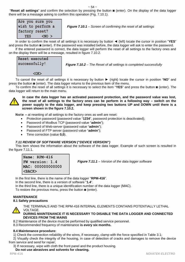
~ 54 ~
RPM-416 NOVATEK-ELECTRO
“Reset all settings” and confirm the selection by pressing the button (enter). On the display of the data loggerthere will be a message asking to confirm this operation (Fig. 7.10.1).
Figure 7.10.1 – Screen of confirming the reset of all settings
In order to confirm the reset of all settings it is necessary by button (left) locate the cursor in position “YES”and press the button (enter). If the password was installed before, the data logger will ask to enter the password.
If the entered password is correct, the data logger will perform the reset of all settings to the factory ones andon the display there will be a message, resulted in figure 7.10.2.
Figure 7.10.2 – The Reset of all settings is completed successfully
To cancel the reset of all settings it is necessary by button (right) locate the cursor in position “NO” andpress the button (enter). The data logger returns to the previous item of the menu.
To confirm the reset of all settings it is necessary to select the item “YES” and press the button (enter). Thedata logger will return to the main menu.
In case the data logger has an activated password protection, and the password value was lost,the reset of all settings to the factory ones can be perform in a following way – switch on thepower supply to the data logger, and keep pressing two buttons UP and DOWN until there is ascreen shown in the figure 7.10.2.
Note – at resetting of all settings to the factory ones as well are reset: Protection password (password value “1234”, password protection is deactivated); Password of Modbus TCP (password value “admin”); Password of Web-server (password value “admin”); Password of FTP server (password value “admin”); Time correction (value 0,0).
7.11 REVIEW OF SOFTWARE VERSION (“DEVICE VERSION”)This item shows the information about the software of the data logger. Example of such screen is resulted in
the figure 7.11.1.
Figure 7.11.1 – Version of the data logger software
In the first line, there is the name of the data logger “RPM-416”.In the second line, there is a version of software “1.4”.In the third line, there is a unique identification number of the data logger ( ).To restore the previous menu, press the button (enter).
MAINTENANCE8.1 Safety precautions
THE TERMINALS AND THE RPM-416 INTERNAL ELEMENTS CONTAINS POTENTIALLY LETHALVOLTAGE.DURING MAINTENANCE IT IS NECESSARY TO DISABLE THE DATA LOGGER AND CONNECTED
DEVICES FROM THE MAINS8.2 Maintenance of the device must be performed by qualified service personnel.8.3 Recommended frequency of maintenance is every six months.
8.4 Maintenance procedure:1) Check the connection reliability of the wires, if necessary, clamp with the force specified in Table 3.1;2) Visually check the integrity of the housing, in case of detection of cracks and damages to remove the device
from service and send for repair;3) If necessary, wipe with cloth the front panel and the product housing.
Do not use abrasives and solvents for cleaning.

~ 55 ~
NOVATEK-ELECTRO RPM-416
9 SERVICE LIFE AND MANUFACTURER WARRANTY9.1 The lifetime of the data logger is 10 years. Upon expiration of the service life, contact the manufacturer.9.2 Shelf life is 3 years.9.3 Warranty period of the RPM-416 operation is 5 years from the date of sale.During the warranty period of operation (in the case of failure of the data logger) the manufacturer is responsible
for free repair of the product.ATTENTION! IF THE PRODUCT HAS BEEN OPERATED IN VIOLATION OF THE REQUIREMENTS OF THIS
MANUAL, THE MANUFACTURER HAS THE RIGHT TO REFUSE IN WARRANTY SERVICE.9.4 Warranty service is performed at the place of purchase or by the manufacturer of the product.9.5 Post-warranty service of the data logger is performed by the manufacturer at current rates.9.6 Before sending for repair, the data logger should be packed in the original or other packing excluding
mechanical damage.Earnest request: indicate the reason for return in the notice of faults field at the return of the device or in case of
submitting for warranty service or post-warranty service.
10 TRANSPORTATION AND STORAGEThe data logger in the original package is permitted to be transported and stored at the temperature from minus
45 to +60°C and relative humidity of 80%.
11 ACCEPTANCE CERTIFICATERPM-416 has been manufactured and accepted in accordance with the requirements of current technical
documentation and classified as fit for operation.
Seal Chief of QCD Date of manufacture _____________ _________________
Date of sale _______________________
12 NOTICES OF CLAIMS____________________________________________________________________________________________________________________________________________________________________________________________________________________________________________________________________________________________________________________________________________________________________________________________________________________________________________________________________________________________________________________________________________________________________________________________________________________________________________________________________________________________________________________________________________________________________________________________________________________________________________________________________________________________________________________________________________________________________________________________________________________________________________________
In case of any questions, please contact:NOVATEK ELECTRO INDIA PVT. LTD.C-30, Patparganj Industrial Area,Delhi - 110092, INDIA tel. (+91 11) 42143253 tel/fax (+91 11) 43010600www.novatek-electro.in
~ 56 ~
RPM-416 NOVATEK-ELECTRO
Appendix A(recommended)
Connection of the data logger to Ethernet
The connection of the data logger to Ethernet network requires the interlink compliance of settings ofall connected devices. Connection to the network of not correctly adjusted data logger may result inthe communication failure, as well as on other devices in the network. As a rule the connection to thenetwork of more than 2 interconnected devices should be performed only by the qualified personnel(network administrator).
.1 IP-addressingAt communication of the device via Ethernet network over TCP / IP protocol, in order to distinguish the
data transmitter and recipient every device uses a special settings of IP-addressing.The device keeps in memory its own unique IP-address within one subnet (four bytes are recorded in way
of four integral numbers in range 0 - 255, separated by dots), subnet mask, which is the same for all devices inthe subnet (is written similarly to IP-address) and IP-address gateway, which is used for communication withother networks.
For correct communication of the devices in the subnet it is necessary to observe the following provisions: The subnet mask should be the same for all devices in that sub network. As a rule in small local
sub networks, the mask 255.255.255.0 is used. The mask begins with a group of bits set in 1,followed by the group of bits set in 0;
Group of Bits, in IP-addresses of devices, which are set in mask in 1, are similar and represent theaddress of subnet. For mask 255.255.255.0 in local subnets more often are used the addresses,beginning with 192.168.0.1;
Group of Bits, in IP-addresses of devices, which are set in mask in 0, is unique for every devicewithin one sub network.
In most of the cases, a new device (for example, a router) which is connected to network already hasconnection with other networks. Often the addresses 192.168.0.1, 192.168.0.100 or 192.168.0.101 arereserved for it. In this case, other devices in the network receive IP-Address of this device as an addressgateway. Indication of this address is not obligatory for communication between the devices in subnet and isused only for communication of devices of one subnet with devices in other subnets.
The factory settings of addressing of the data logger RPM-416 are resulted in Table .1.
Table .1Parameter Value
IP-address 192.168.0.2Subnet mask 255.255.255.0Gateway 192.168.0.1
For the data logger communication with a client-device (and any other devices in the same subnet) themask 255.255.255.0 and address starting with 192.168.0 are used. The fourth byte of address can be of anyvalue in range 1–255, except 2.
In case of indirect connection (between RPM-416 and client-device), and in network with several devices,address can not be equal to any of addresses of other devices in the subnet.
.2 Setting of client-deviceSetting of addressing of client-device should be performed according to the documentation of this device
and to the software used in it.There is an example of setting the personal computer (PC) with operational system (OS) Windows XP or
Windows 7 for direct connection to RPM-416 with factory settings.For setting the network address in operational system (OS) Windows you should open the list of network
connections OS. For this, depending on the version of OS, perform the following operations: For OS Windows XP:
1) Enter into OS with profile of administrator;2) Select «Start->Control panel»;3) Select category «Net and Internet connection»;4) Open item «Network connections».
for OS Windows 7:1) Enter into OS with profile of administrator;2) Select «Start->Control panel»;

~ 57 ~
NOVATEK-ELECTRO RPM-416
3) Select category «Net and Internet»;4) Open item «Center of net and common access management»;5) In the list of tasks (on the left of panel) select «Adapter parameters change».
In the opened screen of connections, select the adapter which addressing should be changed. Manycomputers have only one adapter, which will be shown in this screen.
Click on the icon of the selected adapter with mouse right button, in the appeared menu select the item«Properties». The screen of properties will open, an example of such screen is resulted in the figure .1.
In the opened screen in the list of connection components select «Internet Protocol (TCP/IPv4)». Makesure that component is activated (marked by sign in the list).
Press the button «Properties». The screen of the properties of TCP/IPv4 will open, an example of suchscreen is resulted in figure .2.
Select the option «Use the next IP-address».In field «IP-Address» write the address in range 192.168.0.1–192.168.0.255 (except 192.168.0.2, which is
used by the data logger).In field «Mask of subnet» write «255.255.255.0».The fields «Main gateway», «Preferable DNS-server», «Alternative DNS-server» should be left blank.Press «OK» for closing the window of protocol setting.Press «OK» for closing the window of adapter setting.
Fig. .1 – Example of connection properties screenin Windows 7
Fig. .2 – Example of protocol TCP/IPv4properties screen in Windows 7

~ 58 ~
RPM-416 NOVATEK-ELECTRO
Appendix B(recommended)
Connection of the Data logger to Internet
It is strongly recommended that connection of the data logger to Internet is carried out undersupervision of system administrator of local network or representative of internet provider.
For connection of the data logger to Internet use the following recommendations: obtain a dedicated line with a static IP-address from internet provider (further in text the provider); inform the provider about MAC-address of the data logger
The direct connection of the data logger to the provider’s cable is not recommended.At connection of the data logger via a router (routing gateway) the provider’s cable should be connected to
a router slot “WAN” (usually with a color indication without number, depending on the router manufacturer theindication can differ, see the router documentation).
The connection Ethernet cable is used for connection of the data logger to the router (supplied with thedata logger).
Guided by the router manual adjust the router for connection to Internet network according to theprovider’s recommendations. In the router settings switch on the redirection of incoming packages to IP-Address of the data logger (factory setting – 192.168.0.2).
At addressing to the data logger in Internet network you should used the IP-Address obtained from theprovider.
The integrated in RPM-416 security access features are not intended against malicious network attacks(especially the attacks which purpose is blocking the access to the device).
You should secure the connection of the data logger to Internet network by standard means of protection(for example, Firewall).

~ 59 ~
NOVATEK-ELECTRO RPM-416

~ 60 ~
RPM-416 NOVATEK-ELECTRO