operating manual and spare part list · trifasico ó monofasico, con el enfriamiento de la misma...
TRANSCRIPT

EDIZIONE 01/12
OPERATING MANUAL
AND SPARE PART LIST
ROTARY VANES COMPRESSORS
MODEL GC
GENERAL EUROPE VACUUM Srl VIA DEL COMMERCIO, 9
20090 BUCCINASCO (MI) ITALY TEL. ++39 02 48841120 FAX ++39 02 4453957
e-mail: [email protected] http://www.gevac.com

GC compressors – Operating Manual Pag 2 di 22

GC compressors – Operating Manual Pag 3 di 22
DICHIARAZIONE DI CONFORMITA’ COMPLIANCE DECLARATION DECLARACION DE CONFORMIDAD KONFORMITAETSERKLAERUNG DECLARATION DE CONFORMITÉ
COMPRESSORE ROTATIVO VACUUM PUMP / COMPRESSOR POMPE A VIDE/ COMPRESSEUR VAKUUMPUMPE / KOMPRESSOREN Modelo Modello Model
GC 6-12-45-100
Matricula Matricola Serial nº. Maschinen nº. Nº. De machine
Desde/ Da/ From: 1201001 Hasta/ A/ To: 1212500
Año de Construcción – Anno di costruzione - Baujahr Year of manufacture – Anèe de construction
2012
LA FIRMA – LA SOTTOSCRITTA – THE UNDERSIGNED – LA SOUSSIGNEE – DIE UNTERZEICHNENDE
GENERAL EUROPE VACUUM, S.r.l. Via del Commercio, 9 * I-20090 BUCCINASCO (Milano) ITALY
Dichiara sotto la propria responsabilità che il suddetto macchinario denominato : compressore rotativo a palette, accoppiato direttamente ad un motore elettrico trifase o monofase con raffreddamento realizzato da ventola motore; ventola calettata sul giunto di trasmissione o serpentina/radiatore è conforme alle seguenti direttive: 2006/42/CE, 73/23CEE, 89336CEE e i loro successivi emendamenti. .
Declares under its own liability that the new machine herebolow described as : Rotary vanes vacuum pump directly coupled to electric threephase/monophase motor with air cooling carried out by means of motor fan, fan directly coupled to the trasmission joint or by coil/radiator, fully complies the following directives n° 2006/42/CE, 73/23CEE, 89/336CEE and the following amendaments.
Declare sous sa propre rèspon-sabilitè que la machine neuve dont la description est la suivante: pompe couplèe directment à un moteur electrique triphase ou 1phase. Le refroidissement est realise directment par ventilateur du moteur, par une ventilateur couplèe sur le manchon de trasmis-sion ou par le radiateur /serpentin de refroidissement, est conforme aux dispo-sition: 2006/42/CE, 73/23CEE, 89/336CEE et aux modification successiv
Erklaert unter eigener Verantwortung, dass die neue Maschine nachstehend beschrieben als: Vakuumpumpe direkt gekoppelt mit elektri-schen Motor, dreifasig oder einfasig.Die kuehlung erfolgt direkt durch den Ventilator des Motors, Ventilator direkt an Trasmissionskupplunggekoppelt oder Radiator kuehl-schlange. Entspricht den gesetzlichen Bestimmungen unter folgenden Vorschriften 2006/42/CE, 73/23CEE 89/336CEE und allen nachtraeglichen Abaenderungen.
Declara bajo su propia responsabilidad, que la maquina indicada arriba denominada: bomba rotativa de paletas, acoplada directamente a un motor eléctrico, trifasico ó monofasico, con el enfriamiento de la misma producido por el ventilador del motor; el ventilador instalado directamente en la unión de transmisión motor/bomba ó serpentín/radiador, es conforme a las directiva 2006/42/CE, 73/23CEE, 89336CEE y sus sucesivas actualizaciones.
GC compressors – Operating Manual Pag 4 di 22
GENERAL INSTRUCTIONS The instructions shown in the present manual are related to : Oil lubricated and rotary vanes compressors model GC Range: from 6 to 100 Drawings and data stated in this manual are not binding. G.E.V. reserves the right, firmly keeping the performances and the operation of the described compressor to alter the design and any data herewith given , any time that it deems appropriate, either for improving the pumps same or for any other reasons, without being forced to immediately bring to up to date this manual.
It is absolutely mandatory that these operating instructions be read and understood prior to the compressor installation and start up. The GEV compressors have been manufactured according to the newest technical standards and safety regulations as per “Machines directives 2006/42 CE” and additions. If not properly installed or used without following the stated instructions, dangerous situations or damage might occur.
Warning This signal indicates the operating procedures that must be strictly observed to prevent hazard to persons..
Warning When working on the compressor or on the pumping system, it is important to strictly observe and follow the “Operating instructions “. Before starting any work disconnect the unit from power supply. Take all the precautions for ensuring that the pump cannot suddently start If the compressor has pumped hazardous gases, it will be absolutely necessary to determine the nature of the hazard and take the appropriate safety precautions. Take the appropriate precautions prior to open the intake or exhaust port. GEV ASSISTANCE If you send a compressor to General Europe Vacuum indicates whether it is free of substances damaging the health or whether it is contaminated. If contaminated, indicate the nature of hazard.
Warning The compressor must be packed in a way that will not be damaged during shipping and that no harmful substances can escape from the package.

GC compressors – Operating Manual Pag 5 di 22
GENERAL INDEX DESCRIPTION PARAGRAPH General instructions -- Technical assistance --
OPERATING INSTRUCTIONS DESCRIPTION A - Operating principle A.1 - Field of application A.2 - Lubricants A.3 - Transport, lifting, manipulation and stock A.4 INSTALLATION B - Installation B.1 - Connection to system B.2 - suction side B.2.1 - exhaust side B.2.2 - Electric connection B.3 - start-up B.4 - running B.5 - Oil drops regulations B.6 MAINTENANCE C - Maintenance schedule C.1 - Oil check C.2 - Oil level C.2.1 - Oil condition C.2.2 Suction filters D Troubleshooting guide E Exploded drawings and components list F Overall dimensions, technical datas G Safety instructions for installation in hazardous areas H

GC compressors – Operating Manual Pag 6 di 22
OPERATING INSTRUCTIONS A. Description A.1 Operating principle : The GC compressors are single stage, oil-sealed rotary vanes. The compressors are driven by a directly flanged motor by means of coupling or directly assembled without coupling. The rotor assembled eccentrically to the stator has 6 vanes dividing the pump chamber. Each section’ volume varies periodically during the rotor rotation as the blades, running freely inside the rotor cavities, are pushed, thanks to centrifuge power, toward the cylinder walls. The gas, during the expansion chamber phase, gets sucked thru the suction inlet. The sucked gas flows thru the pumping chamber, where, during the next phase, gets compressed and exhausted thru the oil separator together with the nebulized lubrication oil, at a changeable pressure regulated by a valve. The oil injected into the pumping chamber assures tightness, lubrication and pump cooling. The oil cycle is maintained by the pressure difference exhisting between the oil and the suction. A.2 Field of application GC compressors have been engineered for their application in the range of pressure till 2 bar g. They can handle gases as air, LPG, or in special esecutions as Biogas, Methan. A.3 Lubricants General Europe Vacuum recommends its special oil “TYPE G 880” to allow vacuum pump works properly If you use a non-approved oil, GEV cannot guarantee that the pumps will meet their operating specifications ( ultimate pressure, pumping speed, operating temperature etc. ) However the warranty is voided only if a non-approved oil adversely affects the operation and reliability of the pump. Use of others special grades lubricants for special applications is allowed after GEV approval. If a synthetic oil has been selected, GEV recommends its synthetic oil “TYPE SYG 880” Caution:don’t mix different oil into the pump. A specific procedure has to be applied to change standard oil by a synthetic oil. This specific procedure has to be done by GEV For any additional information and/or explanation please refer to our office .
GENERAL EUROPE VACUUM Srl VIA DEL COMMERCIO 9
20090 BUCCINASCO (MI) ITALY TEL. ++39 02 48841120 FAX ++39 02 4453957
e-mail: [email protected] http://www.gevac.com

GC compressors – Operating Manual Pag 7 di 22
A.4 Transport, lifting, manipulation and stock Compressor is supplied complete with electric motor. Usually the compressor is supplied without oil. Running without it would affect compressor performances seriously. Fill up the compressor before start up moving it always in the upright position. The slope angle must be minimized, otherwise the oil will pour out. Avoid any other orientation while moving compressor. For compressor lifting use the proper bands, balacing the weight properly.
Warning Check if compressor leaks oil because there is slip danger . Use proper lifting equipment and make sure that all the safety norms have been observed. Beware Until the compressor is put back in to service once more, it should be stored in a dry place , preferably at room temperature. Before taking the compressor out of service, it should be properly disconnected from the system, purged with dry nitrogen and the oil should be renewed too. Both inlet and exhaust ports must be blanked off using the supplied seals . If the compressor has been shelved for over one year, standard maintenance must be effected and oil must be refreshed too before putting it into service again. Contact GEV again for any information. B. INSTALLATION B.1 Installation It is essential to observe the following instructions, step by step, to ensure a safe start up. Start up shall have to be carried out by skilled and trained personell. Compressor must be installed on a flat and horizontal surface.

GC compressors – Operating Manual Pag 8 di 22
Beware The oil level cannot be read properly if the compressor is tilted. The environmental temperature should be between 12°C. and 40° C. To ensure proper air cooling to the compressor it is advisable to leave sufficient space aside being sure that the motor cooling side is free. Moreover check to leave enough space close to the compressor allowing easy access to all the components, like : filter, oil level indicator, oil fill up and exhaust cap. B. 2 Connection to system The standard compressor does not fit for being installed in explosion and hazard areas. Take contact with GEV if you are planning to install it in such areas. Compressor must be installed by skilled and trained personell. Take all safety precautions. B.2.1 Suction side
Warning -Disconnect compressor from mains when connected to suction piping. - Use flexible hoses either in suction and at discharge so that you can easily remove for making maintenance - The suction piping must at least have the same diameter of the compressor connection . A smaller piping can reduce the pumping speed. - Both raw material and seals used for piping assembling must comply with sucked gases nature. - If the sucked gas contains dust, it is absolutely necessary to equip a filter. In the event of steams suction, it is advisable to contact GEV in advance. - No solid or liquid particles shall enter the pump. B.2.2 Exhaust side We recommend you to connect a discharge hose fit for any type of sucked gas. This is always necessary when the discharge gases are dangerous . The working pressure could to be regulated by a valve installed at the outlet.
Warning Follow all the precautions when sucting process gases. The exhaust piping section must be like the compressor exhaust hose .

GC compressors – Operating Manual Pag 9 di 22
B. 3 ELECTRIC CONNECTIONS
Warning Check that electric main is off before connecting the junction box or in case you have to operate on it- The connection to main must be carried out by a skilled technician and according to the safety norms. Refer to the scheme underneath for connection. Connect the feeding cables to the junction box. The European standards declare to protect the electric motor with a proper device calibrated according to the datas shown on motor lable.
Warning If any motor or electric switch cuts the compressor out. Re-start up of the compressor can be carried out only manualy. After having carefully checked the stopping reason. Compressor can start up also when suction is already loaded. After connecting motor and every time you alter the wiring, check motor rotation direction, check the arrow shown on motor lable. During check, suction must be open. If motor rotation is wrong, oil may be flushed back from the suction fitting. Switch on the motor for a while for checking the situation . If the motor rotates contrarily to the correct direction, stops it immediately and inverte 2 phases of the electric connection to wiring. A prolonged motor rotation in the wrong direction will damage the compressor.

GC compressors – Operating Manual Pag 10 di 22
B.4 Start-up Compressor must be filled up to the half of the oil sight glass. Always check that oil level & and motor rotation are correct before start up it for the first time or before changing electric connections Compressor can run to a temperature over 12° C. B.5 Running
Warning Compressor when running is hot and some parts could reach a surface temperature of 80°C. Burning risk in case of touching. Read carefully the warning printed on the red lable stickered to compressor. B.6 Oil drippers regulation Check during the compressor running that each driller get 3-4 drops/ minute till model 20, 5-6 drops/minute till model 80 and 6-8 drops/minute till model 300. To adjust the driller screw or unscrew the up-side cover (sometime with a screwdriver) C. MAINTENANCE
Warning Disconnect electric supply before disconnecting compressor. If compressor has sucked dangerous substances, check the nature risk and take the adequate
safety precautions. When wasting the exhaust oil , follow the environmental norms, any intervention must be
skilled personell Use only original spare parts Maintenance or repairing being wrongly carried out or using unproper materials could damage The pump Maintenance or repairing must be carried out by skilled technicians as an uncorrect intervention
on compressor could affect its lifetime and performances thus cancelling the warranty. Do not use weared gaskets, use new one.

GC compressors – Operating Manual Pag 11 di 22
C.1 Maintenance schedule The maintenance schedule stated in the maintenance sheet underneath are approximate values for a normal function of compressor. Difficult environmental conditions and/or aggressive gases can increase significally the maintenance interventions.
CHECK AND MAINTENANCE FREQUENCY Oil level check Daily Oil conditions check Depending upon process Replacement of vanes & gaskets Every year or whenever an oil leak occures C.2 Oil check C. 2.1 Oil level The oil casing has two oil sight glasses.: - at the bottom, where the oil must never go below - at the top, for normal check of oil status The oil lstatus must always be in the middle of the oil sight glass
C. 2.2 Oil condition Under normal conditions, oil looks transparent. If it gets black, must be changed. Final pressure is compromized, if gases or liquids are mixed into the oil Unscrew the oil drainage tap and let the oil flow into the proper tank carefully following the safety norms. Close the oil draining tap. Unscrew the oil fill-up tap again and fill-up compressor with fresh oil up to the bottom limit of the oil-glass level, switch on the compressor shortly and then change the oil again following the above mentioned procedure. Do follow all the environmental instructions when wasting exhausted oil

GC compressors – Operating Manual Pag 12 di 22
D. SUCTION FILTERS They are mainly used for avoiding foreign substances in the inlet and they are usually supplied upon request. They can be with paper cartridge ( type GFC ) or metal ( type GFM) depending from final application. The oil-sump filter ( type GFOP ) is particularly used for being used in heavy dusty environments. Type GFM- GFC Type GFOP
Type GFM - GFC GFOP 20 60 100 200 300 35 120 350 500
Capacity (m3/h)
20 65 110 200 300 36 120 350 600
Weight (kg) 0,5 0,7 0,9 2 2,5 0,5 1,9 3,7 13 A 90 135 135 135 135 72 130 185 320 B 150 130 210 270 375 165 215 340 560
C Ø ½”G 1”G 1”G 2”G 2”G ¾”G 1”G 2”G 4”G D Ø - 1”G 1”G 2”G 2”G ¾”G 1”G 2”G 4”G E Ø ½”G - - - - - - - -
F 165 - - - - 60 110 150 210 G 123 100 177 140 260 130 155 225 412
H Ø 50 68 68 95 95 - - - - I Ø 26 26 26 65 65 - - - -
Oil q.ty (gr.) - - - - - 125 350 700 1300

GC compressors – Operating Manual Pag 13 di 22
E. TROUBLESHOOTING GUIDE
FAULTS CAUSES REMEDY Compressor does not start or the thermal device starts after few
Motor is not properly connected The thermal device has not been properly adjuested The Volts do not fit with the motor’s one Compressor is stucked
Connect motor correctly Readjust the thermal device Replace motor Replace compressor
Compressor does not start easily, vanes noise and higher power absorption
The rotating sense is uncorrect The oil temperature is too low, ( less then 12°C) Oil is too viscous Pump has been stopped since long time Exhaust piping is clogged
Change the rotation direction Heat the environment and
the oil with a less viscousity one Use the correct oil and clean during the comp. running with gasoline Let compressor run with closed suction untill hot Clean all the exhaust piping
Compressor does not reach the stated Tag pressure
Measuring instrument is damaged or unsuitable Leaking from both oil and pipings Oil missing in the compressor Shaft seals out of order or uncorrectly positioned Poor lubrication due to : . unsuitable or contaminated oil . oil filter clogged . oil pipings clogged Drippers are not regulated
Check the measuring technique and the used instruments Check and tighten all fittings housed both on pipings and oil Fill up compressor with oil Replace the tight rings Change the oil Clean the oil lines Clean the vacuum line See the details B.6

GC compressors – Operating Manual Pag 14 di 22
FAULTS CAUSES REMEDY Compressor is too hot
Cooling air is not enough Piping or fan is dirt Too high temperature of the gas aspired Insufficent oil quantity in the compressorOil recyrculation piping obstructed Oil filter is dirt
Place compressor in a more aired location Clean with air or solvent Verify the system and the reiability of the compressor Restore oil level Verify and clean Replace oil filter
Compressor leaks oil
Fittings and oil cyrculation piping are not tight or are spoiled Shaft seals too much used
Verify the fittings, tight them, verify the pipings and eventually replace them Replace the seals
Oil is dark Oil has been used for too many hours Oil is not the correct one Oil is burned by the too high temperature of the pump
Drain oil and replace it Replace oil filter and oil Check the compressor
Motor runs but the compressor doesn’t
Coupling insert is broken
Verify & replace
Compressor is clogged and the motor doesn’t run
Compressor needs oil Vanes broken
Verify & fill up Verify & replace the vanes
Compressor is noisy
Oil level is down Vane don’t move during running
Fill up oil Change oil and clean with gasoline into the running
GC compressors – Operating Manual Pag 15 di 22
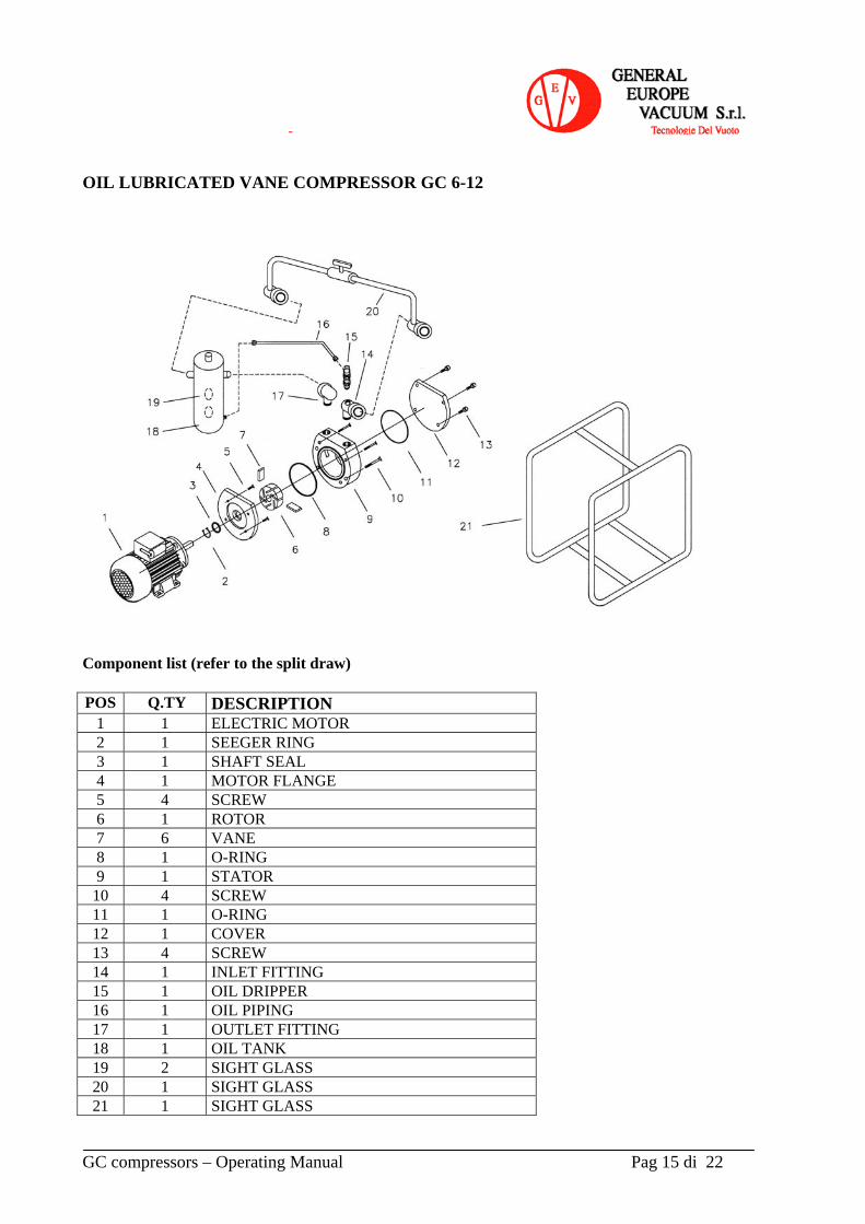
OIL LUBRICATED VANE COMPRESSOR GC 6-12 Component list (refer to the split draw)
POS Q.TY DESCRIPTION
1 1 ELECTRIC MOTOR 2 1 SEEGER RING 3 1 SHAFT SEAL 4 1 MOTOR FLANGE 5 4 SCREW 6 1 ROTOR 7 6 VANE 8 1 O-RING 9 1 STATOR
10 4 SCREW 11 1 O-RING 12 1 COVER 13 4 SCREW 14 1 INLET FITTING 15 1 OIL DRIPPER 16 1 OIL PIPING 17 1 OUTLET FITTING 18 1 OIL TANK 19 2 SIGHT GLASS 20 1 SIGHT GLASS 21 1 SIGHT GLASS


COMPRESSOR GC45 Spare list (relating to exploded drawing) Pos. Q.ty CODE DESCRIPTION Pos. Q.ty CODE DESCRIPTION
1 1 - ENSEMBLE BY-PASS VALVE 32 1 20 00 31 FAN PROTECTION CARTER 2 1 17 00 14 COVER PROTECTION CARTER 35 8 - SCREW 3 2 - SCREW WITH FLAT WASHER 36 4 - SCREW 4 4 - ALLEN SCREW 37 1 17 00 04 CAP 5 1 17 00 02 DISCHARGE FLANGE 38 1 O-RING 6 1 20 00 16 SPRING 39 1 17 00 06 CAP PUMP 7 1 20 00 15 SUCTION PAN AND O-RING 40 1 - BEARING 8 1 20 00 20 SUCTION WASHER 41 2 - O-RING 9 1 - SEEGER 42 4 17 00 11 VANE
10 1 20 00 17 FILTER 43 1 80 05 09 ROTOR 11 1 20 00 09 COVER SUCTION 44 1 - BEARING 12 4 - SCREW 45 4 - PIN 13 1 - WEDGE 46 1 20 00 03 BODY PUMP 14 1 17 00 08 JOINT PUMP SIDE 48 1 17 00 05 COVER PUMP MOTOR SIDE 15 1 - PIN 50 1 SEAL 16 1 - SCREW ANCHOR 52 1 17 00 03 OIL DRIPPER SUPPORT 17 1 - PIN 53 1 - BRACKET OIL TANK 18 4 - SCREW MOTOR FIXING 54 1 - SEEGER 19 1 17 00 07 TURRET 55 1 - SCREW WITH FLAT WASHER FOR
BEARING LOCK 21 2 - SELF-THREADING WITH FLAT WASHER 56 1 - SCREW LOCKING CARTER 22 2 OIL DRIPPER 57 1 - NIPPLES G3/4-G3/4 23 1 17 00 01 OIL TANK 58 1 - T-CONNECTOR a T G3/4-G3/8-G3/4
24 1 MOTOR 59 1 - PIPE diameter 10
25 1 20 00 13 PUMP PROTECTION CARTER 60 1 - BY-PASS VALVE
26 1 - DISCHARGE WASHER 61 1 - T-CONNECTOR G1”-G3/8-G1”
27 1 - NO VIBRANT 62 4 - NUT WITH OGIVE
28 1 - NUT
29 1 - ENSEMBLE PUMP 30 1 20 00 65 COOLING FAN 31 1 - SCREW WITH FLAT WASHER

GC compressors – Operating Manual Pag 18 di 22

GC compressors – Operating Manual Pag 19 di 22
OIL TANK Spare list (relating to exploded drawing)
POS QUANTITY DESCRIPTION GC 45
1 6 SCREW 2 1 OUTLET COVER 3 2 OIL MIST ELIMINATOR PLATE 4 1 OUTLET GASKET 5 2 NUT 6 2 SPRING 8 1 FILL UP PLUG
10 1 OIL TANK 18 2 SIGHT GLASS 19 2 SIGHT GLASS GASKET 20 1 OIL DRAIN PLUG 21 1 O-RING PLUG 22 2 NUT 23 2 WASHER 24 2 ANTIVIBRATION FOOT 38 1 BODY OUTLET GASKET 39 1 OIL TANK COVER 40 1 OIL TANK GASKET 205 2 OIL MIST ELIMINATOR

GC compressors – Operating Manual Pag 20 di 22

GC compressors – Operating Manual Pag 21 di 22
GC compressors – Operating Manual Pag 22 di 22
H . SAFETY INSTRUCTIONS FOR INSTALLATION IN HAZARDOUS AREAS Before to install rotary vane compressor type GC in potentially explosive areas, classified accordingly to ATEX Directive 94 / 9 / EC please read carefully these instructions.
Read carefully Operation and Maintenance Manual
Verify vanes compressor is suitable to operate in the choose area, both for the external environment and for the sucked gases and vapours. Area classification is customer responsibility.
Verify that electric motor, instruments and all the compressor accessories are suitable for the area
Verify very carefully ATEX conformity of the following equipments: - Electric motor must be EEx and suitable for the gas group, category and temperature class
- The same for the coupling joint
It’s mandatory to install all instruments and accessories as specified in the risks analysis for the ATEX category and temperature class of installation
A thermal probe is mounted in the warmer part of the compressor. Set point calibration must be at temperature below the temperature class of the area.
An oil level switch is mounted on the compressor to avoid compressors running without lubrication
Install the compressor in a clean and dust free room. All the compressor external surfaces will be clean periodically. Dust on hot surface must be carefully avoided.
Verify, every 6 months, the cooling fun integrity. No clearence must be in the joint points. Eventually change it.
Not more than 5-6 start up cycles per hour must be performed. If the process need an high number of start / stop cycles, install an isolation valve on the compressors suction and leave the compressor running continuously.
For any modification to compressor running or performance parameters please contact us before
Is necessary to connect to earth the compressor with a suitable cable. THESE SAFETY INSTRUCTION MUST BE OBSERVED CAREFULLY TOGETHER WITH THE OPERATION AND MAINTENANCE MANUAL OF ROTARY VANE COMPRESSOR TYPE GC