operating manual - aidacare
TRANSCRIPT

Patient Support Systems Pty Ltd: Suite 1A, Level 2, 802 Pacific Highway, Gordon Sydney NSW Australia 2072Tel: +61 2 9844 5456 Fax: +61 2 9844 5445 Mob: 0402 346 525 Email: [email protected]
ABN: 44 143 523 415
Warranty Limitations
1. Patient Support Systems Pty Ltd, its distributors, dealers, officers, directors, employees or agents shall have no liability or responsibility to any customer, other person or entity with respect to any liability, loss or damage caused directly or indirectly by use or performance of the Product or arising out of any breach of this Warranty, including but not limited to any damages resulting from inconvenience, personal injury, loss of time, property, revenue or profit or any indirect, special, incidental or consequential damages, even if Patient Support Systems Pty Ltd or its authorized dealers have been advised of the possibility of such damages.
2. The sole remedy for breach of the limited warranty granted herein shall be repair or replacement of the Patient Support Systems Pty Ltd products.
3. Some states in the United States and countries elsewhere do not allow the limitation on how long an implied warranty lasts or the exclusion of incidental or inconsequential damages, so the above limitations on exclusions may not apply.
4. This limited Warranty gives you specific legal rights and you may also have other legal rights, which vary from state to state or country to country.
No salesperson, representative, agent or authorized dealer of Patient Support Systems Pty Ltd is authorized to make any guarantee, warranty, or representation in addition to the foregoing Warranty.
Operating Manual
Theraflow™
Alternating Mattress Replacement SystemsModel MRS-TFW-001 Standard

2 19
System Specifications
5. Any Warranty claim being made within the Warranty periods specified above.
6. No misuse or damage either willful or accidental caused to the Product by freight agents, distributors or end users.
Warranty terms and conditions are subject to change at any time without notice.
Warranty Claims Procedure
In the event of a product defect during the Warranty period, the customer should
• Contact Patient Support Systems Pty Ltd or its authorized agent
• Provide proof of purchase and date of delivery
• Patient Support Systems Pty Ltd or its authorized agent will, at their discretion, unless otherwise provided by law:
- correct the defect by product repair without charge for parts and labor; or
- replace the product with the same or similar model; or refund the purchase price.
Warranty Exclusions
This Warranty does not cover:
1. Components not specifically designated by Patient Support Systems Pty Ltd as being eligible for this Warranty including but not limited to consumables (such as fuses).
2. Patient Support Systems Pty Ltd components not supplied by it or its authorized dealers.
3. Defects resulting from non-compliant or improper Product installation, testing, use, repair or storage.
4. Unauthorized attachment, removal, or alteration of any part of the Product.
5. Damage due to loading in excess of the weight capacity displayed on the Product specifications.
6. Normal “wear and tear” as determined by Patient Support Systems Pty Ltd.
7. Cosmetic damage, stains, punctures, cuts, damage to electrical cords, rips or tears, dents, electrical overload, surge, spikes and or lost/missing parts.
8. Abuse, misuse, neglect, accident or any other condition whatsoever that is beyond the control of Patient Support Systems Pty Ltd.
9. Use of the Product for purposes other than those for which it was designed
10. Failure to monitor or operate the product in accordance with applicable specifications and good industry practice
18 3
Customer “Warranty Against Defect” Statement
Patient Support Systems Pty Ltd warrants each of its products to perform in accordance with published specifications for specified time periods, when subjected to normal, proper and intended use.
Our goods come with guarantees that cannot be excluded under the Australian Consumer Law. You are entitled to a replacement or refund for a major failure and compensation for any other reasonably foreseeable loss or damage. You are also entitled to have the goods repaired or replaced if goods fail to be of acceptable quality and the failure does not amount to a major failure.
Patient Support Systems Pty Ltd warrants that their products and approved parts sold under this warranty:
1. Will be free from defects in materials and workmanship, and shall conform to and perform in accordance with the related documentation supplied by Patient Support Systems Pty Ltd including specifications and instructions on product.
2. Will comply with the CE and UL standard quality requirements in force at the time of manufacture.
Commencement of Warranty Period
The duration of the Warranty is a maximum period of two (2) years for control units and one (1) year for soft goods or as specified per individual product. The Warranty period commences and is calculated from the date of delivery to you from a Patient Support System’s authorised agent.
Warranty repairs do not extend the length of the warranty period. All replaced parts and products on which refunds are made become the property of Patient Support Systems Pty Ltd. New or reconditioned parts and products may be used in the performance of warranty service. Customers will be charged for repair or replacement of the product made after the expiration of the warranty period, at Patient Support Systems Pty Ltd’s or their authorised agent’s rates and terms then in effect.
Warranty Conditions
Patient Support Systems Pty Ltd’s obligations pursuant to this Warranty are conditional upon:
1. Proof of purchase being presented with any claim.
2. Whole product claims will require matching serial numbers for the base, top cover and control unit.
3. All product installation being undertaken in strict accordance with instructions provided with the Product.
4. The Product consisting of only Patient Support Systems Pty Ltd approved parts.
Limited Warranty
System SummarySystem Description 4
System Components 5
Recommended Usage 6
Safety Protocols 7
Initial System Setup 8-9Control Unit Operation 10-11
Care & CleaningOn Site Cleaning 12
Machine Washing 12
Coverlet Cleaning 13
Mattress Removal 14
Service Schedule 15
Troubleshooting 16
Specifications 17
Limited Warranty 18-20
Contents

4 17
System Descripton
Congratulations on your hire or purchase of a Theraflow alternating mattress replacement system. The Theraflow with its Dynam-U-link cell technology and Cellstay ultra-stretch coverlet represents one of the greatest advances in alternating support technology since its inception.
Dynam-U-link cells use elastic transfer straps so that inflating cell sets literally pull down the deflating sets beside them. This results in faster, more sustained pressure release.
The Cell Stay coverlet positioned between the cells and top cover comforts and insulates the patient from the colder cells without compromising therapy. This coverlet also guards against reperfusion injury in patients with delicate vasculature and tissue.
Your mattress system has the following features.
Control Unit:• Powerful yet quiet 20 LPM compressor with non-continuous operation
• Auto startup with choice of three modes - Static, Active and Care
• Choice of three comfort settings
• Incline mode for adding extra support pressure
• Simple tamper resistant control interface with audio visual diagnostics
• Easy to reach CPR side disconnection
Mattress:• Fully welded top cover and base for complete infection control
• Removable cell section for easy separation of base for cleaning
• Four static head cells to prevent dizzyness and disorientation
• Clear PVC base bonds to any metal bed base avoiding need for straps
• Fourteen alternating Dynam-U-link cell pairs for faster, lower and longer cell deflation
• Cell Stay insulating hi-stretch Coverlet
• Internal power cord removes chance of damage underneath the bed
System Specifications
Control Unit
Dimensions: W 25 x H 25 x D 17cm
Weight 3kg
Mode of Operation Non-Continuous
Power Rating 240V 50Hz 12VA
Transport Function Hose End Cap
Air Flow 20 Litres per Minute
Auto Startup 3
Comfort Override Control 3
Self Diagnostics 3
Audible/Visual alarm 3
Mute Function 3
Static Mode - timeout after 1 hour 3
Care Mode - timeout after 20 mins 3
Incline Mode 3
Auto Anti Tamper 3
CE Certification and C-Tick Listed
N27882
Mattress Replacement
Dimensions L 200 x W 90 x H 25cm
No. of Cells 28 (paired)
Static Head Cells (included) 4
Cell Material TPU, High Density
Top Cover Dartex/Equivalent - welded
Base Assorted PU and PVCs, welded
Cell Cycle Paired 1 in 2
Alternating Mode 14 minute cycle
Infection Control:
Welded Top Cover and Base
Internal infection control coverlet
Positioning Handles 2 aside
ARTG Certification 175810
16 5
Problem Cause Solution
Troubleshooting & FAQs
Control Unit does not operate or fault light flashes & alarm sounds
The fault light below flashes and alarm sounds
Cell or Cells rising up above adjoining cells
There may be a disconnection in the power supply
There is a leak somewhere in the cell or air hose connection system
A cell end press stud has disconnected.
1. Ensure all cord connections from wall plug, breakaway connection at head end and pump connector are properly seated in their sockets.
2. Check Control Unit fuse under power socket - flick open with small flat head screwdriver and replace fuse if necessary. Only use fuse type 10Amp 250Volt
1. Ensure that the CPR hose connector is properly attached to the side of the control unit.
2. Remove the top cover and listen for any hiss of air from the cells. The powerful 20 litre pump should ensure that you can hear where there is a cell leak. If you still cannot hear - remove the coverlet and or run the back of your hand along the top of the cells to find the air leak. Also look for any deformed cells as these may have internal weld failures leading to leaks of air between separate internal chambers.
Once the faulty cell is found - remove and replace with the same type.
3. Look for any disconnection between hoses and their T or L connectors. Don’t forget to also check whether the air hoses are correctly connected to each of the cells.
1. Open top cover and check along the sides of the inside base section. It is easy to see immediately if any of the external press studs have become disconnected. One press stud set connects two cells - if the studs are faulty - replace those cells.
The Theraflow alternating mattress replacement system is provided with the following standard components.
1 Alternating Mattress Replacement with internal power cord.
2 Digital Control Unit
3 Break-Away Power Cord
4 Theraflow Operating Manual
5 Theraflow Quick Setup Guide
6 Wash Bag
7 Wheeled Carry Bag
Alternating Mattress Replacement System
Auto Quick Setup Guide1
2
3
4
40 mins
20 mins
Remove mattress roll from carry bag and lay on bed base at foot end.
Try to avoid hanging the control unit in an exposed position if a lower hang point is available.
Connect air hose to control unit (Connector can attach either way around)
Connect Sensor Jack to its Port underneath air hoses.(Control Unit will NOT operate without sensor!)
Connect male power cord to control unit as shown.
Connect breakaway power cord into wall socket.
Turn on control unit at switch near power socket.
Mattress will take up to40 minutes to inflate.
Press and hold Unlock button for 2 seconds to activate control panel.
Engage Care Mode for patient transfer onto mattress.
Care Mode will auto disengage after 20 mins.
2 secs
Control Unit Operation
Patient Support Systems Pty Ltd: Suite 1A, Level 2, 802 Pacific Highway, Gordon Sydney NSW Australia 2072Tel: +61 2 9844 5456 Fax: +61 2 9844 5445 Email: info@ patientsupportsystems.com
5 The Theraflow Automatic Sensor System is designed to automatically adjust to patient weight, position & profile
Press the pressure setting button at left All three lights will flash. The system takes 8 minutes to adjust to the patient’s weight
Locked Mode: Press for 2 seconds to unlock all controls
Active Mode: Default Mode for active alternation therapy
Care Mode: Maximum pressure for patient transfers Will default to Active Mode after 20 minutes
Static Mode: Engage for transport or meals for comfort Will change back to alternation after 1 hour
CPR
Ensure CPR tag is closed!
Operating Manual
Theraflow™
Alternating Mattress Replacement Systems
Model MRS-TFW-001 Standard
Model MRS-TFW-001P with battery backup
Model MRS-TFW-002P Bariatric with battery backup
7
2
4
5
3
6
1
System Components

6 15
Recommended Usage
IndicationsThe Theraflow alternating mattress replacement standard model MRS-TFW-001 is indicated for patients weighing between 40 and 180kg. The system is designed for large area reperfusion therapy in patients suffering from Stage 1 to Stage 4 pressure areas, or assessed at high risk of exhibiting these conditions.
In addition - patients suffering from low blood flow or ischemia in the extremities may also benefit from the application and release of pressure to encourage blood flow in these areas.
Contra-IndicationsPatient conditions for which the Theraflow alternating mattress replacement would be contra-indicated would be the following.
• Non-stable spinal cord injury
• Cervical traction
• Any patient exhibiting unease or agitation on alternating surfaces
• Patients weighing under 40kg or over 200kg or otherwise too wide for a standard single (<90cm) mattress width.
Intended Care SettingThe following care settings are recommended for the Theraflow alternating mattress replacement system.
• Home care
• Aged care facilities
• Palliative care
• Long term or extended rehabilitation
• General hospital
• Intensive Care Units
Service Schedule
Service ScheduleThe Theraflow alternating mattress replacement has been designed for easy maintenance and service. The following schedule should be used as a guide for maintaining the optimal performance of the system.
When Necessary and between Patient Use• On site clean and disinfection of top cover, base and control unit casing.
see previous cleaning and disinfection instructions. Do not use system without top cover attached.
• Inspection of top cover and base for any strike through or damage.
• Inspection of coverlet for soiling or contamination - clean or replace.
• Inspection of electrical cords for proper connection, damage and any possible interference with moving bed parts
• Inspection of elastics. Between patient use or every 4 months -turn mattress over and see through base windows the condition and attachment of the elastics. If any are detached, re-attach. If any are frayed or corrugated at the edges, replace those elastics.
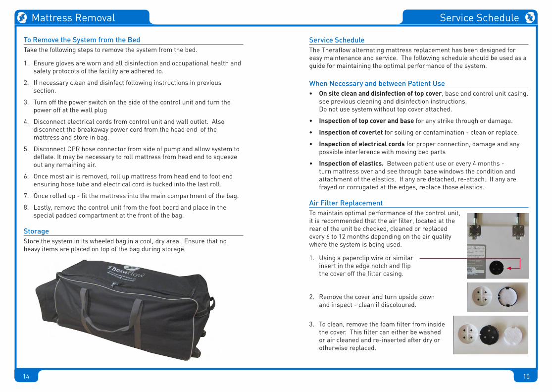
Air Filter ReplacementTo maintain optimal performance of the control unit, it is recommended that the air filter, located at the rear of the unit be checked, cleaned or replaced every 6 to 12 months depending on the air quality where the system is being used.
1. Using a paperclip wire or similar insert in the edge notch and flip the cover off the filter casing.
2. Remove the cover and turn upside down and inspect - clean if discoloured.
3. To clean, remove the foam filter from inside the cover. This filter can either be washed or air cleaned and re-inserted after dry or otherwise replaced.
14 7
To Remove the System from the BedTake the following steps to remove the system from the bed.
1. Ensure gloves are worn and all disinfection and occupational health and safety protocols of the facility are adhered to.
2. If necessary clean and disinfect following instructions in previous section.
3. Turn off the power switch on the side of the control unit and turn the power off at the wall plug
4. Disconnect electrical cords from control unit and wall outlet. Also disconnect the breakaway power cord from the head end of the mattress and store in bag.
5. Disconnect CPR hose connector from side of pump and allow system to deflate. It may be necessary to roll mattress from head end to squeeze out any remaining air.
6. Once most air is removed, roll up mattress from head end to foot end ensuring hose tube and electrical cord is tucked into the last roll.
7. Once rolled up - fit the mattress into the main compartment of the bag.
8. Lastly, remove the control unit from the foot board and place in the special padded compartment at the front of the bag.
StorageStore the system in its wheeled bag in a cool, dry area. Ensure that no heavy items are placed on top of the bag during storage.
Mattress Removal Safety Protocols
Important Recommendations for General Use of SystemMattress:
Do not place any layers of material between the patient and top cover of the mattress! Doing so will compromise therapy! This includes the following: i) Hospital sheets - regular or fitted ii) Sheepskins or equivalent iii) Incontinence sheets iv) Slide sheets v) Electric heating blankets The mattress top cover is fully sealed and designed for the patient to lie directly on top. All that is required is an antibacterial wipe-down or machine wash when necessary. See Care Section for more information.
Ensure the patient’s clothing does not cause skin damage due to ties, buttons, creases, seams, objects in pockets and jewellery
Do not place any sharp items on or near the mattress such as syringes or scalpels or any instrument that could hole the top cover
Do not place any solid item/s on top of the system besides the patient
Do not spill any liquids onto the control unit. If a spillage occurs then: i) Turn off power to the control unit at the wall ii) Disconnect the power cord from the control unit iii) Wipe dry any excess moisture on the external casing iv) Check that the interior of the power connector, plug and switch is dry
Failure to do the above may lead to component corrosion and or electrical safety hazards to carers and patients
Do not use system in the presence of any flammable anaesthetic mixture with air, nitrous oxide or oxygen or in the presence of smoking materials or open flame - risk of explosion
Control Unit
Do not open the control unit as there is risk of electric shock. Control units should only be opened by approved technicians or warranty will be voided
Avoid blocking the air intake filter at the rear of the control unit
Ensure that the power leads are undamaged and properly connected

8 13
System Setup Regular
Alternating Mattress Replacement System
Auto Quick Setup Guide1
2
3
4
40 mins
20 mins
Remove mattress roll from carry bag and lay on bed base at foot end.
Try to avoid hanging the control unit in an exposed position if a lower hang point is available.
Connect air hose to control unit (Connector can attach either way around)
Connect Sensor Jack to its Port underneath air hoses.(Control Unit will NOT operate without sensor!)
Connect male power cord to control unit as shown.
Connect breakaway power cord into wall socket.
Turn on control unit at switch near power socket.
Mattress will take up to40 minutes to inflate.
Press and hold Unlock button for 2 seconds to activate control panel.
Engage Care Mode for patient transfer onto mattress.
Care Mode will auto disengage after 20 mins.
2 secs
Control Unit Operation5 The Theraflow Automatic Sensor System is designed to automatically adjust to patient weight, position & profile
Press the pressure setting button at left All three lights will flash. The system takes 8 minutes to adjust to the patient’s weight
Locked Mode: Press for 2 seconds to unlock all controls
Active Mode: Default Mode for active alternation therapy
Care Mode: Maximum pressure for patient transfers Will default to Active Mode after 20 minutes
Static Mode: Engage for transport or meals for comfort Will change back to alternation after 1 hour
CPR
Ensure CPR tag is closed!
Care & Cleaning
Coverlet CleaningThe Hyperstretch Coverlet can be machine washed and dried by following the printed instructions on the top side of the coverlet itself - reprinted below.
Coverlet Removal and ReplacementThe coverlet can be removed for seperate cleaning by simply removing the top cover and then unziping away from the clear PVC flaps on each side. With the Bariatric model you need to be unzip the coverlet skirt from head end to 360 degrees.
12 9
On-site CleaningThe Theraflow alternating mattress replacement system features fully welded outer surfaces. When necessary the top cover and base can be cleaned and disinfected on site once the patient has been removed from the mattress.
The following on-site cleaning procedure is recommended for top cover and control unit. Note that a summary of the below is printed at the foot end flap of the top cover. Do not immerse the control unit in water!
1. Ensure gloves are worn and all disinfection and occupational health and safety protocols of the facility are adhered to.
2. Wipe down with a clean cloth using a disinfectant solution comprising of hand hot water and a neutral detergent or with a sodium hypochlorite solution (0.1% or 1000 parts per million available chlorine. Proprietary disinfectants may be used provided manufacturer’s instructions are followed.
3. All cleaning agents and disinfectants must be thoroughly rinsed off and the surface dried before storage or re-use. Failure to do this may result in the accumulation of reagent that could damage the polyurethane coating, react with the bed frame or negate the bio-compatibility results of the fabric.
Machine WashingThe system is designed as a “mattress within a mattress” so that the base and top cover can be easily separated from the cell section which is fitted within its own inner base.
Machine wash the outer mattress top cover as follows;
Wash at a temperature up to 71° (160°F), using normal detergents
In washing machines, it may be difficult to wet out full covers. Correspondingly, spinning and tumbling may not remove water trapped between layers. It may be helpful to interrupt the washing or drying cycles to alleviate this.
Machine Drying:Drying may be achieved by hanging out, spinning or tumbling at temperatures up to 130°C (266°F) - Do not mangle.
Care & Cleaning Control Unit Functions
Unlocking the system After start up, or after 5 minutes without user input, the system will automatically lock to prevent tampering. The Unlock LED will light up to indicate this. To change any settings, simply press AND HOLD the Unlock Button for 2 seconds to activate controls.
Positioning or transferring patient on bed To position the patient on the mattress or to generally manoeuvre or transfer the patient press the Care Button. This will inflate the mattress to maximum pressure and provide a stable surface. The system will automatically revert to the previous mode after 20 minutes.
Automatic Patient profiling If the mattress head section is raised more than 25 degrees, a sensor will automatically engage Profile Mode and extra air will be added to the system for
greater patient support and to prevent bottoming out.
Comfort Auto Control
The system is designed to automatically adjust to patient weight, position and profile. Once the patient is placed on the mattress press the comfort button. All three lights will
flash and the system will take 8 minutes to adjust to the patient.
PRESSURE POWER
TRANSPORT
LOCK/UNLOCK THERAPY
PATIENTTRANSFER

10 11
Operation Mode Selection The control unit has three modes of operation.
Active/Dynamic Mode is operational by default and provides an alternating surface for patient therapy.
Care Mode provides maximum pressure and stability. It is designed primarily for patient transfer and handling.
Transport Mode is designed for patient comfort and support as well as in preperation for bed transport without power. This mode inflates all cells to the automatic or selected pressure and will revert back to Active Mode after 1 hour
PRESSURE POWER
TRANSPORT
LOCK/UNLOCK THERAPY
PATIENTTRANSFER
Control Unit Functions
Alarms and diagnostics:
The control unit features an audio visual alarm diagnostic which will activate if there is a malfunction.
If the left button flashes and alarms, it indicates that there is a problem with the mattress or an air leak to the control unit. If the right button flashes and alarms, it indicates that there is an electrical malfunction or problem within the control unit itself.
Both these audio alarms can be muted by pressing the indicator which is flashing. This will mute the alarm for 20 minutes. If the malfunction has not been resolved however, the alarm will re-activate.
For more information on alarms and faults with the system, please see the Troubleshooting section of this manual.
PRESSURE POWER
TRANSPORT
LOCK/UNLOCK THERAPY
PATIENTTRANSFER
Control Unit Functions

12 9
On-site CleaningThe Theraflow alternating mattress replacement system features fully welded outer surfaces. When necessary the top cover and base can be cleaned and disinfected on site once the patient has been removed from the mattress.
The following on-site cleaning procedure is recommended for top cover and control unit. Note that a summary of the below is printed at the foot end flap of the top cover. Do not immerse the control unit in water!
1. Ensure gloves are worn and all disinfection and occupational health and safety protocols of the facility are adhered to.
2. Wipe down with a clean cloth using a disinfectant solution comprising of hand hot water and a neutral detergent or with a sodium hypochlorite solution (0.1% or 1000 parts per million available chlorine. Proprietary disinfectants may be used provided manufacturer’s instructions are followed.
3. All cleaning agents and disinfectants must be thoroughly rinsed off and the surface dried before storage or re-use. Failure to do this may result in the accumulation of reagent that could damage the polyurethane coating, react with the bed frame or negate the bio-compatibility results of the fabric.
Machine WashingThe system is designed as a “mattress within a mattress” so that the base and top cover can be easily separated from the cell section which is fitted within its own inner base.
Machine wash the outer mattress top cover as follows;
Wash at a temperature up to 71° (160°F), using normal detergents
In washing machines, it may be difficult to wet out full covers. Correspondingly, spinning and tumbling may not remove water trapped between layers. It may be helpful to interrupt the washing or drying cycles to alleviate this.
Machine Drying:Drying may be achieved by hanging out, spinning or tumbling at temperatures up to 130°C (266°F) - Do not mangle.
Care & Cleaning Control Unit Functions
Unlocking the system After start up, or after 5 minutes without user input, the system will automatically lock to prevent tampering. The Unlock LED will light up to indicate this. To change any settings, simply press AND HOLD the Unlock Button for 2 seconds to activate controls.
Positioning or transferring patient on bed To position the patient on the mattress or to generally manoeuvre or transfer the patient press the Care Button. This will inflate the mattress to maximum pressure and provide a stable surface. The system will automatically revert to the previous mode after 20 minutes.
Automatic Patient profiling If the mattress head section is raised more than 25 degrees, a sensor will automatically engage Profile Mode and extra air will be added to the system for
greater patient support and to prevent bottoming out.
Comfort Auto Control
The system is designed to automatically adjust to patient weight, position and profile. Once the patient is placed on the mattress press the comfort button. All three lights will
flash and the system will take 8 minutes to adjust to the patient.
PRESSURE POWER
TRANSPORT
LOCK/UNLOCK THERAPY
PATIENTTRANSFER
8 13
System Setup Regular
Alternating Mattress Replacement System
Auto Quick Setup Guide1
2
3
4
40 mins
20 mins
Remove mattress roll from carry bag and lay on bed base at foot end.
Try to avoid hanging the control unit in an exposed position if a lower hang point is available.
Connect air hose to control unit (Connector can attach either way around)
Connect Sensor Jack to its Port underneath air hoses.(Control Unit will NOT operate without sensor!)
Connect male power cord to control unit as shown.
Connect breakaway power cord into wall socket.
Turn on control unit at switch near power socket.
Mattress will take up to40 minutes to inflate.
Press and hold Unlock button for 2 seconds to activate control panel.
Engage Care Mode for patient transfer onto mattress.
Care Mode will auto disengage after 20 mins.
2 secs
Control Unit Operation5 The Theraflow Automatic Sensor System is designed to automatically adjust to patient weight, position & profile
Press the pressure setting button at left All three lights will flash. The system takes 8 minutes to adjust to the patient’s weight
Locked Mode: Press for 2 seconds to unlock all controls
Active Mode: Default Mode for active alternation therapy
Care Mode: Maximum pressure for patient transfers Will default to Active Mode after 20 minutes
Static Mode: Engage for transport or meals for comfort Will change back to alternation after 1 hour
CPR
Ensure CPR tag is closed!
Care & Cleaning
Coverlet CleaningThe Hyperstretch Coverlet can be machine washed and dried by following the printed instructions on the top side of the coverlet itself - reprinted below.
Coverlet Removal and ReplacementThe coverlet can be removed for seperate cleaning by simply removing the top cover and then unziping away from the clear PVC flaps on each side. With the Bariatric model you need to be unzip the coverlet skirt from head end to 360 degrees.
14 7
To Remove the System from the BedTake the following steps to remove the system from the bed.
1. Ensure gloves are worn and all disinfection and occupational health and safety protocols of the facility are adhered to.
2. If necessary clean and disinfect following instructions in previous section.
3. Turn off the power switch on the side of the control unit and turn the power off at the wall plug
4. Disconnect electrical cords from control unit and wall outlet. Also disconnect the breakaway power cord from the head end of the mattress and store in bag.
5. Disconnect CPR hose connector from side of pump and allow system to deflate. It may be necessary to roll mattress from head end to squeeze out any remaining air.
6. Once most air is removed, roll up mattress from head end to foot end ensuring hose tube and electrical cord is tucked into the last roll.
7. Once rolled up - fit the mattress into the main compartment of the bag.
8. Lastly, remove the control unit from the foot board and place in the special padded compartment at the front of the bag.
StorageStore the system in its wheeled bag in a cool, dry area. Ensure that no heavy items are placed on top of the bag during storage.
Mattress Removal Safety Protocols
Important Recommendations for General Use of SystemMattress:
Do not place any layers of material between the patient and top cover of the mattress! Doing so will compromise therapy! This includes the following: i) Hospital sheets - regular or fitted ii) Sheepskins or equivalent iii) Incontinence sheets iv) Slide sheets v) Electric heating blankets The mattress top cover is fully sealed and designed for the patient to lie directly on top. All that is required is an antibacterial wipe-down or machine wash when necessary. See Care Section for more information.
Ensure the patient’s clothing does not cause skin damage due to ties, buttons, creases, seams, objects in pockets and jewellery
Do not place any sharp items on or near the mattress such as syringes or scalpels or any instrument that could hole the top cover
Do not place any solid item/s on top of the system besides the patient
Do not spill any liquids onto the control unit. If a spillage occurs then: i) Turn off power to the control unit at the wall ii) Disconnect the power cord from the control unit iii) Wipe dry any excess moisture on the external casing iv) Check that the interior of the power connector, plug and switch is dry
Failure to do the above may lead to component corrosion and or electrical safety hazards to carers and patients
Do not use system in the presence of any flammable anaesthetic mixture with air, nitrous oxide or oxygen or in the presence of smoking materials or open flame - risk of explosion
Control Unit
Do not open the control unit as there is risk of electric shock. Control units should only be opened by approved technicians or warranty will be voided
Avoid blocking the air intake filter at the rear of the control unit
Ensure that the power leads are undamaged and properly connected
6 15
Recommended Usage
IndicationsThe Theraflow alternating mattress replacement standard model MRS-TFW-001 is indicated for patients weighing between 40 and 180kg. The system is designed for large area reperfusion therapy in patients suffering from Stage 1 to Stage 4 pressure areas, or assessed at high risk of exhibiting these conditions.
In addition - patients suffering from low blood flow or ischemia in the extremities may also benefit from the application and release of pressure to encourage blood flow in these areas.
Contra-IndicationsPatient conditions for which the Theraflow alternating mattress replacement would be contra-indicated would be the following.
• Non-stable spinal cord injury
• Cervical traction
• Any patient exhibiting unease or agitation on alternating surfaces
• Patients weighing under 40kg or over 200kg or otherwise too wide for a standard single (<90cm) mattress width.
Intended Care SettingThe following care settings are recommended for the Theraflow alternating mattress replacement system.
• Home care
• Aged care facilities
• Palliative care
• Long term or extended rehabilitation
• General hospital
• Intensive Care Units
Service Schedule
Service ScheduleThe Theraflow alternating mattress replacement has been designed for easy maintenance and service. The following schedule should be used as a guide for maintaining the optimal performance of the system.
When Necessary and between Patient Use• On site clean and disinfection of top cover, base and control unit casing.
see previous cleaning and disinfection instructions. Do not use system without top cover attached.
• Inspection of top cover and base for any strike through or damage.
• Inspection of coverlet for soiling or contamination - clean or replace.
• Inspection of electrical cords for proper connection, damage and any possible interference with moving bed parts
• Inspection of elastics. Between patient use or every 4 months -turn mattress over and see through base windows the condition and attachment of the elastics. If any are detached, re-attach. If any are frayed or corrugated at the edges, replace those elastics.
Air Filter ReplacementTo maintain optimal performance of the control unit, it is recommended that the air filter, located at the rear of the unit be checked, cleaned or replaced every 6 to 12 months depending on the air quality where the system is being used.
1. Using a paperclip wire or similar insert in the edge notch and flip the cover off the filter casing.
2. Remove the cover and turn upside down and inspect - clean if discoloured.
3. To clean, remove the foam filter from inside the cover. This filter can either be washed or air cleaned and re-inserted after dry or otherwise replaced.

16 5
Problem Cause Solution
Troubleshooting & FAQs
Control Unit does not operate or fault light flashes & alarm sounds
The fault light below flashes and alarm sounds
Cell or Cells rising up above adjoining cells
There may be a disconnection in the power supply
There is a leak somewhere in the cell or air hose connection system
A cell end press stud has disconnected.
1. Ensure all cord connections from wall plug, breakaway connection at head end and pump connector are properly seated in their sockets.
2. Check Control Unit fuse under power socket - flick open with small flat head screwdriver and replace fuse if necessary. Only use fuse type 10Amp 250Volt
1. Ensure that the CPR hose connector is properly attached to the side of the control unit.
2. Remove the top cover and listen for any hiss of air from the cells. The powerful 20 litre pump should ensure that you can hear where there is a cell leak. If you still cannot hear - remove the coverlet and or run the back of your hand along the top of the cells to find the air leak. Also look for any deformed cells as these may have internal weld failures leading to leaks of air between separate internal chambers.
Once the faulty cell is found - remove and replace with the same type.
3. Look for any disconnection between hoses and their T or L connectors. Don’t forget to also check whether the air hoses are correctly connected to each of the cells.
1. Open top cover and check along the sides of the inside base section. It is easy to see immediately if any of the external press studs have become disconnected. One press stud set connects two cells - if the studs are faulty - replace those cells.
The Theraflow alternating mattress replacement system is provided with the following standard components.
1 Alternating Mattress Replacement with internal power cord.
2 Digital Control Unit
3 Break-Away Power Cord
4 Theraflow Operating Manual
5 Theraflow Quick Setup Guide
6 Wash Bag
7 Wheeled Carry Bag
Alternating Mattress Replacement System
Auto Quick Setup Guide1
2
3
4
40 mins
20 mins
Remove mattress roll from carry bag and lay on bed base at foot end.
Try to avoid hanging the control unit in an exposed position if a lower hang point is available.
Connect air hose to control unit (Connector can attach either way around)
Connect Sensor Jack to its Port underneath air hoses.(Control Unit will NOT operate without sensor!)
Connect male power cord to control unit as shown.
Connect breakaway power cord into wall socket.
Turn on control unit at switch near power socket.
Mattress will take up to40 minutes to inflate.
Press and hold Unlock button for 2 seconds to activate control panel.
Engage Care Mode for patient transfer onto mattress.
Care Mode will auto disengage after 20 mins.
2 secs
Control Unit Operation
Patient Support Systems Pty Ltd: Suite 1A, Level 2, 802 Pacific Highway, Gordon Sydney NSW Australia 2072Tel: +61 2 9844 5456 Fax: +61 2 9844 5445 Email: info@ patientsupportsystems.com
5 The Theraflow Automatic Sensor System is designed to automatically adjust to patient weight, position & profile
Press the pressure setting button at left All three lights will flash. The system takes 8 minutes to adjust to the patient’s weight
Locked Mode: Press for 2 seconds to unlock all controls
Active Mode: Default Mode for active alternation therapy
Care Mode: Maximum pressure for patient transfers Will default to Active Mode after 20 minutes
Static Mode: Engage for transport or meals for comfort Will change back to alternation after 1 hour
CPR
Ensure CPR tag is closed!
Operating Manual
Theraflow™
Alternating Mattress Replacement Systems
Model MRS-TFW-001 Standard
Model MRS-TFW-001P with battery backup
Model MRS-TFW-002P Bariatric with battery backup
7
2
4
5
3
6
1
System Components
4 17
System Descripton
Congratulations on your hire or purchase of a Theraflow alternating mattress replacement system. The Theraflow with its Dynam-U-link cell technology and Cellstay ultra-stretch coverlet represents one of the greatest advances in alternating support technology since its inception.
Dynam-U-link cells use elastic transfer straps so that inflating cell sets literally pull down the deflating sets beside them. This results in faster, more sustained pressure release.
The Cell Stay coverlet positioned between the cells and top cover comforts and insulates the patient from the colder cells without compromising therapy. This coverlet also guards against reperfusion injury in patients with delicate vasculature and tissue.
Your mattress system has the following features.
Control Unit:• Powerful yet quiet 20 LPM compressor with non-continuous operation
• Auto startup with choice of three modes - Static, Active and Care
• Choice of three comfort settings
• Incline mode for adding extra support pressure
• Simple tamper resistant control interface with audio visual diagnostics
• Easy to reach CPR side disconnection
Mattress:• Fully welded top cover and base for complete infection control
• Removable cell section for easy separation of base for cleaning
• Four static head cells to prevent dizzyness and disorientation
• Clear PVC base bonds to any metal bed base avoiding need for straps
• Fourteen alternating Dynam-U-link cell pairs for faster, lower and longer cell deflation
• Cell Stay insulating hi-stretch Coverlet
• Internal power cord removes chance of damage underneath the bed
System Specifications
Control Unit
Dimensions: W 25 x H 25 x D 17cm
Weight 3kg
Mode of Operation Non-Continuous
Power Rating 240V 50Hz 12VA
Transport Function Hose End Cap
Air Flow 20 Litres per Minute
Auto Startup 3
Comfort Override Control 3
Self Diagnostics 3
Audible/Visual alarm 3
Mute Function 3
Static Mode - timeout after 1 hour 3
Care Mode - timeout after 20 mins 3
Incline Mode 3
Auto Anti Tamper 3
CE Certification and C-Tick Listed
N27882
Mattress Replacement
Dimensions L 200 x W 90 x H 25cm
No. of Cells 28 (paired)
Static Head Cells (included) 4
Cell Material TPU, High Density
Top Cover Dartex/Equivalent - welded
Base Assorted PU and PVCs, welded
Cell Cycle Paired 1 in 2
Alternating Mode 14 minute cycle
Infection Control:
Welded Top Cover and Base
Internal infection control coverlet
Positioning Handles 2 aside
ARTG Certification 175810

18 3
Customer “Warranty Against Defect” Statement
Patient Support Systems Pty Ltd warrants each of its products to perform in accordance with published specifications for specified time periods, when subjected to normal, proper and intended use.
Our goods come with guarantees that cannot be excluded under the Australian Consumer Law. You are entitled to a replacement or refund for a major failure and compensation for any other reasonably foreseeable loss or damage. You are also entitled to have the goods repaired or replaced if goods fail to be of acceptable quality and the failure does not amount to a major failure.
Patient Support Systems Pty Ltd warrants that their products and approved parts sold under this warranty:
1. Will be free from defects in materials and workmanship, and shall conform to and perform in accordance with the related documentation supplied by Patient Support Systems Pty Ltd including specifications and instructions on product.
2. Will comply with the CE and UL standard quality requirements in force at the time of manufacture.
Commencement of Warranty Period
The duration of the Warranty is a maximum period of two (2) years for control units and one (1) year for soft goods or as specified per individual product. The Warranty period commences and is calculated from the date of delivery to you from a Patient Support System’s authorised agent.
Warranty repairs do not extend the length of the warranty period. All replaced parts and products on which refunds are made become the property of Patient Support Systems Pty Ltd. New or reconditioned parts and products may be used in the performance of warranty service. Customers will be charged for repair or replacement of the product made after the expiration of the warranty period, at Patient Support Systems Pty Ltd’s or their authorised agent’s rates and terms then in effect.
Warranty Conditions
Patient Support Systems Pty Ltd’s obligations pursuant to this Warranty are conditional upon:
1. Proof of purchase being presented with any claim.
2. Whole product claims will require matching serial numbers for the base, top cover and control unit.
3. All product installation being undertaken in strict accordance with instructions provided with the Product.
4. The Product consisting of only Patient Support Systems Pty Ltd approved parts.
Limited Warranty
System SummarySystem Description 4
System Components 5
Recommended Usage 6
Safety Protocols 7
Initial System Setup 8-9Control Unit Operation 10-11
Care & CleaningOn Site Cleaning 12
Machine Washing 12
Coverlet Cleaning 13
Mattress Removal 14
Service Schedule 15
Troubleshooting 16
Specifications 17
Limited Warranty 18-20
Contents
2 19
System Specifications
5. Any Warranty claim being made within the Warranty periods specified above.
6. No misuse or damage either willful or accidental caused to the Product by freight agents, distributors or end users.
Warranty terms and conditions are subject to change at any time without notice.
Warranty Claims Procedure
In the event of a product defect during the Warranty period, the customer should
• Contact Patient Support Systems Pty Ltd or its authorized agent
• Provide proof of purchase and date of delivery
• Patient Support Systems Pty Ltd or its authorized agent will, at their discretion, unless otherwise provided by law:
- correct the defect by product repair without charge for parts and labor; or
- replace the product with the same or similar model; or refund the purchase price.
Warranty Exclusions
This Warranty does not cover:
1. Components not specifically designated by Patient Support Systems Pty Ltd as being eligible for this Warranty including but not limited to consumables (such as fuses).
2. Patient Support Systems Pty Ltd components not supplied by it or its authorized dealers.
3. Defects resulting from non-compliant or improper Product installation, testing, use, repair or storage.
4. Unauthorized attachment, removal, or alteration of any part of the Product.
5. Damage due to loading in excess of the weight capacity displayed on the Product specifications.
6. Normal “wear and tear” as determined by Patient Support Systems Pty Ltd.
7. Cosmetic damage, stains, punctures, cuts, damage to electrical cords, rips or tears, dents, electrical overload, surge, spikes and or lost/missing parts.
8. Abuse, misuse, neglect, accident or any other condition whatsoever that is beyond the control of Patient Support Systems Pty Ltd.
9. Use of the Product for purposes other than those for which it was designed
10. Failure to monitor or operate the product in accordance with applicable specifications and good industry practice

Patient Support Systems Pty Ltd: Suite 1A, Level 2, 802 Pacific Highway, Gordon Sydney NSW Australia 2072Tel: +61 2 9844 5456 Fax: +61 2 9844 5445 Mob: 0402 346 525 Email: [email protected]
ABN: 44 143 523 415
Warranty Limitations
1. Patient Support Systems Pty Ltd, its distributors, dealers, officers,directors, employees or agents shall have no liability or responsibilityto any customer, other person or entity with respect to any liability, lossor damage caused directly or indirectly by use or performance of theProduct or arising out of any breach of this Warranty, including but notlimited to any damages resulting from inconvenience, personal injury,loss of time, property, revenue or profit or any indirect, special, incidentalor consequential damages, even if Patient Support Systems Pty Ltd or itsauthorized dealers have been advised of the possibility of such damages.
2. The sole remedy for breach of the limited warranty granted herein shall berepair or replacement of the Patient Support Systems Pty Ltd products.
3. Some states in the United States and countries elsewhere do not allowthe limitation on how long an implied warranty lasts or the exclusionof incidental or inconsequential damages, so the above limitations onexclusions may not apply.
4. This limited Warranty gives you specific legal rights and you may also haveother legal rights, which vary from state to state or country to country.
No salesperson, representative, agent or authorized dealer of Patient Support Systems Pty Ltd is authorized to make any guarantee, warranty, or representation in addition to the foregoing Warranty.
Operating Manual
Theraflow™
Alternating Mattress Replacement SystemsModel MRS-TFW-001 Standard