operating instructions - unoson · the percussion gouge allows you to take soil samples in...
TRANSCRIPT
1
04.19 PERCUSSION DRILLING SETS
M1.04.19.E© February 2006
OPERATING INSTRUCTIONS
Contents
On these operating instructions ......................................................................................................................... 2Introduction .................................................................................................................................................... 21. Checking beforehand .................................................................................................................................. 22. Working method ......................................................................................................................................... 43. Use of the core sampler 04.19.43 ............................................................................................................... 10
3.1 Use of the core sampler with PVC sample tube................................................................................. 103.2 Use of the core sampler (04.19.43) with the foil insertion kit (04.19.43.01) ....................................... 11
4. Making repairs ........................................................................................................................................... 154.1 Replacing the percussion drill cutting shoe ....................................................................................... 15
www.eijkelkamp.com
P.O. Box 4, 6987 ZG Giesbeek, NLT +31 313 880200
F +31 313 880299E [email protected]

2
On these operating instructions
When the symbol shown on the left is placed before a piece of text, this means that an impor-tant instruction follows.
When the symbol shown on the left is placed before a piece of text, this means that an impor-tant warning follows pointing out a risk of injury to the user or damage to the device.
Text in italics means that the actual text is shown on the instrument or display screen.
Introduction
These instructions cover the following subjects:1. Checking beforehand2. Working method3. Performing repairs
The percussion gouge allows you to take soil samples in difficult conditions, especially where hand drilling is not orhardly possible. However, it remains a hand-drilling device with limitations. Drilling in homogeneous soils is usuallydone with little problem. Applying a good working method to deviant soils, which may contain rubble or stones,can avoid many problems!
We try to address a number of important points in this manual that can help to optimise the use of the percussiondrilling set and/or reduce damage to the device.
1. Checking beforehand
When using the Cobra TT hammer (art. no. 04.19.01):
� Check that the petrol is fresh. Petrol older than 3 months must be replaced; the fuel must have a fresh petrolsmell. Use the right mix ratio (1:50).
� Check whether the machine starts and consult the instructions for the hammer.
When using the electrical hammer (art. no. 04.18.80 light design or 04.18.81 heavy design) in combination withthe generator (art. no: 99.13):
� Check the oil level of the generator. Use the right quality of petrol in the generator. Ensure that the generator isplaced in the synthetic collector box and that the insulation guard is connected (see operating instructionsM1.99.13.01).
� Check the percussion hammer and consult the instructions for the hammer.
� The insulation guard (art. 99.13.01) continuously measures the soundness of the insulation of the connecteddevice, e.g. an electric steel hammer. If the insulation value is too low, the voltage supply is interrupted by thecontrol. This prevents any risk of contact with parts carrying current, as a result of, for example, moisture, faultyinsulation, etc. The generator as well as the appliance is secured by using the insulation guard! The insulationguard controls the generator, but only turns off the appliance!
� The synthetic collector box (art. 99.13.03) is used to store the generator to prevent fuel and/or oil leakage intothe soil.
� The aluminium step-up (art. 99.16) is used to create a more ergonomic working height.
!
Text
�

3
� The fibre glass utility probe is 105 cm long and has a cone with a diameter of 19 mm. The utility probe isstrongly insulating and can therefore be used safely to probe the drilling point for cables, conduits and pipes.
Before drilling, check whether there are (electricity) cables, pipes or conduits in the ground(consult Klic). Use the utility probe to safely probe the drilling point. Choose another drillingpoint if they are present.
� The gloves (art. no. 01.11.13) offer protection against small wounds resulting from any burrs on the percussiongouges and protect against contact with any soil contaminants.
Advice (not included as standard in the set):� Vibration-absorbing gloves, especially for electrical percussion hammer;� Footwear with steel caps;� Hearing protective helmet;� Safety glasses, e.g. for hacking away debris using a geologist’s hammer.
General
Spontaneous breakage can only be prevented by using the equipment correctly.
Check:� Whether all RD32 connections are sound and clean;� The gouges for defects on the cutting edge;� Whether the casing and rod puller clamp and clamping jaw are clean for optimum use;� Whether the set is complete for the work that you intend to use it for!
!
!

4
2. Working method
These operating instructions describe step-by-step how to take asample using percussion gouges of various diameters.
Always wear strong gloves, safety glasses, safetyshoes, ear protection and a hard hat.
Screw the coupling sleeve to the gouge with the largest diameter.
Screw the striking pen into the coupling sleeve. Note: it is left threaded.(Possibly secure with a wrench).
Place the aluminium step-up next to the sampling point. Insert the gougevertically into the soil and place the percussion hammer on top. Stand on thestep-up for a more ergonomic position.
Lay the electricity cable over your shoulder to preventstrangulation with the machine or gouge.
Start the percussion hammer and keep the machine as upright as possibleduring hammering. If the percussion gouge “finds its own way”, follow thisdirection with the machine. Do not force it to one side.If the gouge goes into the ground diagonally, correct the gouge with 1 handwhile the other operates the percussion hammer. Keep the percussionhammer and gouge in line.Keep a good watch on the drop speed. For this, watch a fixed point on thegouge (there is always a spot or a scratch) and check whether the percussiongouge is still dropping.
Has the gouge stopped moving? Stop! You are otherwisetaking unnecessary risks!
Continuing to hammer greatly increases the risk of a break.
Sometimes imperceptible cracks form that can break during the next drilling!
Remove the gouge and any extension rods from the soil and tryto drill with a gouge that has a smaller diameter. You canenlarge the hole later with a gouge that has a larger diameter.
�
!
!
!
5
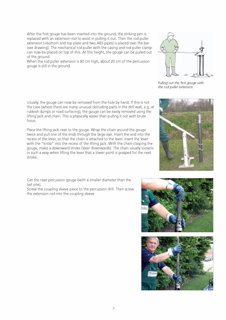
Pulling out the first gouge withthe rod puller extension
After the first gouge has been inserted into the ground, the striking pen isreplaced with an extension rod to assist in pulling it out. Then the rod pullerextension (=bottom and top plate and two ABS pipes) is placed over the bar(see drawing). The mechanical rod puller with the casing and rod puller clampcan now be placed on top of this. At this height, the gouge can be pulled outof the ground.When the rod puller extension is 80 cm high, about 20 cm of the percussiongouge is still in the ground.
Usually, the gouge can now be removed from the hole by hand. If this is notthe case (where there are many unusual obtruding parts in the drill wall, e.g. atrubbish dumps or road surfacing), the gouge can be easily removed using thelifting jack and chain. This is physically easier than pulling it out with bruteforce.
Place the lifting jack next to the gouge. Wrap the chain around the gougetwice and pull one of the ends through the large eye. Insert the end into therecess of the lever, so that the chain is attached to the lever. Insert the leverwith the “knob” into the recess of the lifting jack. With the chain clasping thegouge, make a downward stroke (lever downwards). The chain usually loosensin such a way when lifting the lever that a lower point is grasped for the nextstroke.
Get the next percussion gouge (with a smaller diameter than thelast one).Screw the coupling sleeve piece to the percussion drill. Then screwthe extension rod into the coupling sleeve.

6
Place the gouge with the extension rod into theborehole.
Screw a coupling sleeve to the extension rod and thenattach the striking pen to the coupling sleeve (ifdesired, secure with a wrench).
Attach the percussion hammer to the striking pen.
Stand on the step-up. Start the percussion hammerand keep the machine as upright as possible duringhammering. If the percussion gouge “finds its ownway”, follow this direction with the machine. Do notforce it to one side.If the gouge goes into the ground diagonally, correctthe gouge with 1 hand while the other operates thepercussion hammer. Keep the percussion hammer andgouge in line.

7
Hammer the percussion gouge into the ground.Remove the percussion hammer. Unscrew the strikingpen from the coupling sleeve. If this is stuck, unscrew itusing the tools supplied.
The coupling sleeve can also be unscrewed using theopen ended spanner with the extension arm and thepipe wrench.
If the coupling sleeve is secured too tightly to thepercussion gouge, it can be unscrewed using the pipewrench and the catcher.
The deeper penetrating gouges can be pulled out fromground level.
Place the mechanical rod puller on the extension rod.

8
�
�
Place the universal casing and rod puller clamp on themechanical rod puller and then place the clampingjaw in the casing and rod puller clamp.Check whether the filling ring has been fitted.
Place the handle in the mechanical rod puller.Pull the gouge with extension rod out of theborehole.
Avoid knocking sand and stones into theborehole when raising the gouge.
It may be that you are unable to move the gouge at all. This is usually caused by the fact that it catches on stones/rubble in the wall. These materials may obstruct the removal of the gouge. A jolt will usually solve this.
In extreme cases, this can be solved by placing the machine on the adapter and hammeringbriefly, while keeping the bars under tension using the extraction system (this is only possible ifyou are working with 2 people).
9
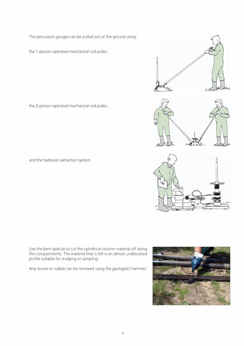
The percussion gouges can be pulled out of the ground using:
the 1-person-operated mechanical rod puller;
the 2-person-operated mechanical rod puller;
and the hydraulic extraction system.
Use the bent spatula to cut the cylindrical column material off alongthe compartments. The material that is left is an almost undisturbedprofile suitable for studying or sampling.
Any stones or rubble can be removed using the geologist’s hammer.
10
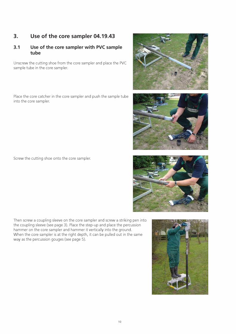
3. Use of the core sampler 04.19.43
3.1 Use of the core sampler with PVC sampletube
Unscrew the cutting shoe from the core sampler and place the PVCsample tube in the core sampler.
Place the core catcher in the core sampler and push the sample tubeinto the core sampler.
Screw the cutting shoe onto the core sampler.
Then screw a coupling sleeve on the core sampler and screw a striking pen intothe coupling sleeve (see page 3). Place the step-up and place the percussionhammer on the core sampler and hammer it vertically into the ground.When the core sampler is at the right depth, it can be pulled out in the sameway as the percussion gouges (see page 5).
11
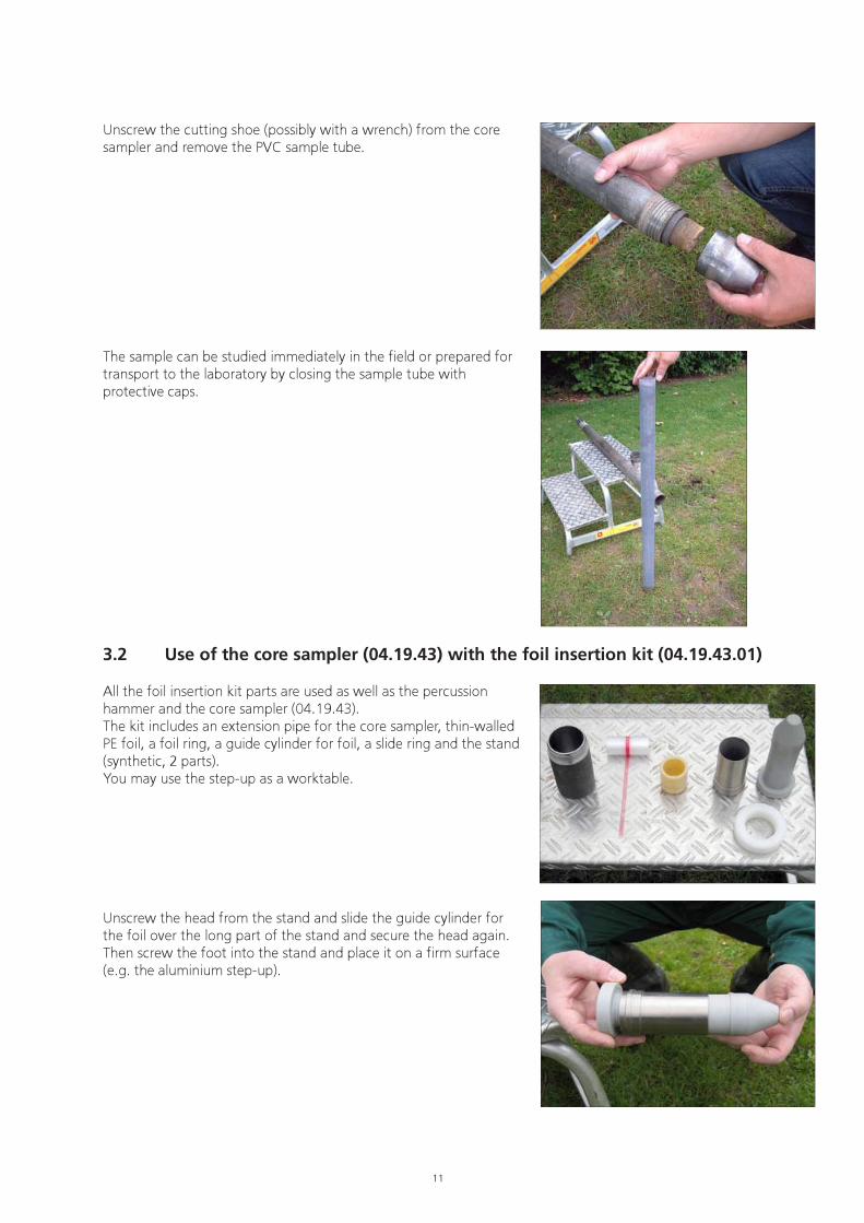
Unscrew the cutting shoe (possibly with a wrench) from the coresampler and remove the PVC sample tube.
The sample can be studied immediately in the field or prepared fortransport to the laboratory by closing the sample tube withprotective caps.
3.2 Use of the core sampler (04.19.43) with the foil insertion kit (04.19.43.01)
All the foil insertion kit parts are used as well as the percussionhammer and the core sampler (04.19.43).The kit includes an extension pipe for the core sampler, thin-walledPE foil, a foil ring, a guide cylinder for foil, a slide ring and the stand(synthetic, 2 parts).You may use the step-up as a worktable.
Unscrew the head from the stand and slide the guide cylinder forthe foil over the long part of the stand and secure the head again.Then screw the foot into the stand and place it on a firm surface(e.g. the aluminium step-up).

12
Take the thin-walled PE foil, unroll the first 20 cm and slide this overthe stand to the end of the foil guide cylinder. Slide the rest of thefoil over the guide cylinder.
Use the slide ring to press the foil compacter onto the metal foilguide cylinder.
Unscrew the foot from the stand and remove the foil guide cylinderwith the foil from the stand.
Slide the synthetic foil ring into the top of the metal foil guidecylinder.Slide a few centimetres of the foil over the foil ring and secure itwith a rubber band or O-ring.
13
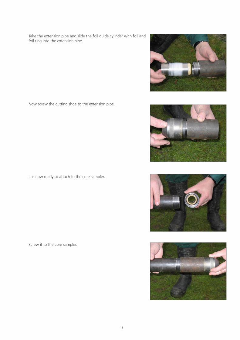
Take the extension pipe and slide the foil guide cylinder with foil andfoil ring into the extension pipe.
Now screw the cutting shoe to the extension pipe.
It is now ready to attach to the core sampler.
Screw it to the core sampler.

14
Attach a coupling sleeve and striking pen to the core sampler, place the percussionhammer and hammer the core sampler into the ground. Withdrawing it from theground is effected as described for the percussion gouges (see page 5).
Unscrew the cutting shoe (if desired, using a wrench) and theextension pipe from the core sampler. Carefully remove the foil withsample from the core sampler.
Remove the foil ring.The sample can be examined immediately (through the foil) or bycutting the foil away. It can otherwise be packed away for transportfor later examination.
The parts and new foil can now be used for the next sampling.
15
Good
Wrong
�
4. Making repairs
4.1 Replacing the percussion drill cutting shoe
Material required:� Welding equipment� Welding electrodes� Burner or oven� Hacksaw� Grinding machine� Cooling facility
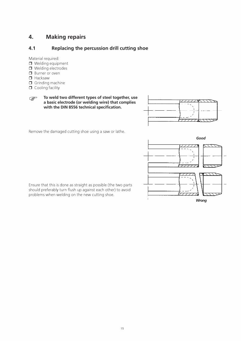
To weld two different types of steel together, usea basic electrode (or welding wire) that complieswith the DIN 8556 technical specification.
Remove the damaged cutting shoe using a saw or lathe.
Ensure that this is done as straight as possible (the two partsshould preferably turn flush up against each other) to avoidproblems when welding on the new cutting shoe.

16
Good
Wrong
Using a grindstone, lathe or belt sander, make a slanted edgeon the cut-off percussion gouge to promote the burn-in of theelectrode.
Before welding the cutting shoe must be tack welded (every120 degrees). Try to do this as straight as possible. One canmark this using a guide (e.g. a ruler or if necessary anelectrode). After this the tack welds are grinded out as far aspossible. Now weld the whole (without welding faults).When MIG - MAG welding use Megafill 710 m diameter 1.2mm as welding wire. As protection gas use Argon mixing gas80-20. After welding, do not forget to remove the slag fromthe joint and file down the tack weld.
The welding joint should now be heated to approx. 200 °Cusing a burner or other heating method. Ensure that thewelding joint is at the right temperature at the moment ofwelding.The cutting edge (first 2 cm) of the percussion drill cutting shoeis hardened inductively. If the preheat temperature is too high,tempering occurs causing the cutting edge to be less hard andthus less wear-resistant.Now place the percussion gouge on a surface on which onecan rotate the gouge. Turn the gouge with one hand whilewelding with the other hand.
After welding, the welded part must be cooled down slowly by,for example, placing the head of the gouge in a container withinsulation material (e.g. vermiculite).
Nothing in this publication may be reproduced and/or made public by means of print, photocopy, microfilm or any other means withoutprevious written permission from Eijkelkamp Agrisearch Equipment.
Technical data can be amended without prior notification.
Eijkelkamp Agrisearch Equipment is interested in your reactions and remarks about its products and operating instructions.