operating instructions stud welder bms-8n · pdf filer serial number* stud welder bms-8n *...
TRANSCRIPT
Operating Instructions
Stud WelderBMS-8N
R

R
Serial number*Stud Welder BMS-8N
* Please enter the serial number, so that this data is immediately available if youneed service support.
Heinz Soyer Bolzenschweißtechnik GmbHEtterschlagInninger Straße 1482237 Wörthsee
Phone08153 - 885 - 0Fax 08153 - 8030Telex 5270 295 heso d
Operating Instructions
Stud WelderBMS-8N

R
SOYER is a registered trade mark of Heinz Soyer BolzenschweißtechnikGmbH.
It is prohibited to transmit or reprint this document, as well as to utilize or disclose its contents, unless this hasbeen expressly granted.Non-compliance with this regulation is liable to compensation. All rights reserved, particularly in the case of apatent grant or GM registration.
We have certified that the contents of this pamphlet correspond to the hard- and software described. Deviations,however, cannot be excluded, so that we cannot warrant for absolute compliance. The data in this documenta-tion, however, have been verified regularly and necessary corrections will be incorporated in future impressions.We appreciate any suggestions for improvement.
Heinz Soyer Bolzenschweißtechnik GmbH 1995 · All rights reserved
Subject to technical alterations
Printed in the Federal Republic of Germany
Date of issue revision 1:Aug. 1, 2000

R
EC Conformity Declarationin compliance with EC Directive on Machinery 89/392/EEC, annex IIA
Producer: Heinz Soyer Bolzenschweißtechnik GmbHEtterschlagInninger Straße 14D-82237 Wörthsee
Declaration: We herewith declare that the machine described in the following and theversion available on the market correspond in design and construction to thefundamental safety and health requirements stipulated by the EC Directive onMachinery. Any modification of this machine without confirmation shallautomatically annul this declaration.
Designation of machine: Stud welder with tip ignition
Machine type: BMS-8N
Machine no.:
Applicable EC directives: EC Directive on Machinery (89/392/EEC) in the version 91/368/EECEC Directive on Low Voltage (73/23/EEC)EC Directive on Electromagnetic Compatibility (89/336/EEC) in the version93/31 EEC
Applied harmonised EN 292-1 and EN 292-2, EN 60 204-1standards,in particular: EN 60 974-1
Applied national standards VBG 1, VBG 5,and technical specifications,in particular: VDE 0544
Date: December 1, 1997
Producer's signature:
Signer's function: Technical Management

R

R

Contents
i
R
Revision 1
Contents
1 General___________________________________________________________________________ 1-11.1 The following should be principally observed ... ____________________________________________ 1-11.2 Application _________________________________________________________________________ 1-21.3 Information on the product _____________________________________________________________ 1-21.4 Type plate ___________________________________________________________________________ 1-21.5 Information on the documentation _______________________________________________________ 1-31.5.1 Chapters of operating instructions _______________________________________________________ 1-31.5.2 Information on operating instructions ____________________________________________________ 1-41.5.3 Conduct in the case of malfunctions _____________________________________________________ 1-41.6 Contacts and service address __________________________________________________________ 1-4
2 Description of stud welder________________________________________________________ 2-52.1 Tip ignition technology ________________________________________________________________ 2-52.2 Stud welder set-up ___________________________________________________________________ 2-52.3 Dimensions __________________________________________________________________________ 2-62.4 Technical data _______________________________________________________________________ 2-72.5 Block diagram _______________________________________________________________________ 2-8
3 Safety instructions________________________________________________________________ 3-93.1 Description of reference signs in the operating instructions __________________________________ 3-93.2 Staff qualification and training __________________________________________________________ 3-103.3 Dangers in the case of non-compliance with safety instructions _____________________________ 3-103.4 Safety-conscious working _____________________________________________________________ 3-103.5 Safety instructions for the operator/user _________________________________________________ 3-113.6 The following should be observed before starting the system ... _____________________________ 3-113.7 Before starting welding ... _____________________________________________________________ 3-123.8 Safety precautions at installation site ____________________________________________________ 3-123.9 Working with the stud welder __________________________________________________________ 3-133.10 Safety instructions for maintenance, inspection and assembly works_________________________ 3-133.11 Unauthorized retrofit and spare parts production _________________________________________ 3-133.12 Inadmissible operating methods _______________________________________________________ 3-143.13 Stopping the stud welder _____________________________________________________________ 3-143.14 The "S" symbol______________________________________________________________________ 3-14
4 Installation of stud welder________________________________________________________ 4-15
5 Initiation_________________________________________________________________________ 5-165.1 Total view __________________________________________________________________________ 5-165.1.1 Operating elements __________________________________________________________________ 5-175.1.2 Display elements ____________________________________________________________________ 5-175.1.3 Connecting elements _________________________________________________________________ 5-175.1.4 Symbols ___________________________________________________________________________ 5-185.1.5 Fuse elements ______________________________________________________________________ 5-185.2 Preparation for initiation_______________________________________________________________ 5-195.2.1 Earth connection ____________________________________________________________________ 5-195.2.2 Connection of stud welding pistol ______________________________________________________ 5-195.2.3 Mains supply________________________________________________________________________ 5-195.3 Operation __________________________________________________________________________ 5-205.4 Welding parameters__________________________________________________________________ 5-20

Contents
ii
R
Revision 1
6 Quality control___________________________________________________________________ 6-216.1 General ____________________________________________________________________________ 6-216.2 Demands on the company ____________________________________________________________ 6-216.3 Proof of qualification _________________________________________________________________ 6-216.4 Type and scope of test _______________________________________________________________ 6-216.4.1 Standard work test __________________________________________________________________ 6-226.4.2 Simplified work test __________________________________________________________________ 6-226.5 Test execution ______________________________________________________________________ 6-226.5.1 Production of samples________________________________________________________________ 6-226.5.2 Visual inspection ____________________________________________________________________ 6-226.5.3 Tensile test _________________________________________________________________________ 6-236.5.4 Bend test __________________________________________________________________________ 6-23
7 Maintenance_____________________________________________________________________ 7-247.1 Stud welder ________________________________________________________________________ 7-247.2 Replacement of components __________________________________________________________ 7-247.3 Fuses ______________________________________________________________________________ 7-25
8 Spare parts______________________________________________________________________ 8-268.1 Spare parts list for stud welder BMS-8N - Overview _______________________________________ 8-268.2 Exploded view of stud welder BMS-8N - Overview ________________________________________ 8-278.3 Spare parts list for stud welder BMS-8N - View A _________________________________________ 8-288.4 Exploded view of stud welder BMS-8N - View A __________________________________________ 8-298.5 Spare parts list for stud welder BMS-8N - View B, C and D ________________________________ 8-308.6 Exploded view of stud welder BMS-8N - View B, C and D _________________________________ 8-31
9 Malfunctions_____________________________________________________________________ 9-329.1 Error codes _________________________________________________________________________ 9-339.2 Troubleshooting _____________________________________________________________________ 9-34
10 Transport and storage___________________________________________________________ 10-36
11 List of standards and guidelines_________________________________________________ 11-37
12 Terms of warranty_______________________________________________________________ 12-38
Appendix A/PS-1 and PS-1K - Tip ignition
1 Adjustment of stud welding pistol_________________________________________________ A-11.1 Adjustment of stud holder ______________________________________________________________A-11.2 Installation of stud holder into stud welding pistols PS-1 and PS-3K __________________________A-21.3 Installation of stud holder into stud welding pistols PS-1K and PS-0K _________________________A-31.4 Adjustment of spring pressure __________________________________________________________A-4
2 Initiation__________________________________________________________________________ A-52.1 Total view ___________________________________________________________________________A-52.2 Connecting stud welding pistols to stud welder____________________________________________A-62.3 Operation ___________________________________________________________________________A-6
3 Spare parts_______________________________________________________________________ A-73.1 Spare parts list for stud welding pistol PS-1K _____________________________________________A-83.2 Exploded view of stud welding pistol PS-1K ______________________________________________A-9

General
1-1
R
Revision 1
1 General
1.1 The following should be principally observed ...
With this stud welder you have purchased a product which
• is state-of-the art technology• fully complies with the current safety requirements and• enables successful working.
Before putting the stud welder into operation, always observe the following :
• Store the operating instructions in a place accessible to every operator• Ensure that the respective operator has read and understood the operating
instructions prior to installation. Each operator should confirm this by signa-ture
• Prevent the stud welder being operated by unauthorized persons• Only trained personnel may operate the stud welder
� MORTAL DANGER
Persons with pacemakers must not operate the stud welder and must notstay in the vicinity of the stud welder while it is running.Ensure that the stud welder is not operated near electronically sensitive life-supporting equipment, such as in intensive care units in hospitals.
WARNINGKeep sufficient distance from electronic devices. When stud welding, highlyintensive electromagnetic fields are created which may permanently damagethese devices (e.g. television sets).
• Moreover, observe the safety instructions in chapter 3.• Call a doctor in case of an accident.
� MORTAL DANGER
The "S" symbol is the symbol for welding current sources permitted foroperation with increased electric danger. The "S" symbol on our studwelders refers exclusively to the welding current circuit and not to thecomplete stud welder.

General
1-2
R
Revision 1
1.2 Application
The SOYER® stud welder BMS-8N with tip ignition allows you to weld pins andthreaded studs of M3 - M8 or Ø 3 - 7.1 mm as well as numerous variousfastening elements made of steel and stainless steel (see chapter 2.4, Techni-cal Data). It is also possible to weld fastening elements made of aluminium andbrass depending on the respective requirements.
The visible side of the workpiece is spared to a large extent from pressuremarks or deformations, so that even thin sheet metals under 1 mm sheetthickness retain their decorative appearance.
If you need consultation or assistance in solving problems, please contacteither our parent company or our field engineers.
1.3 Information on the product
Manufacturer Heinz Soyer Bolzenschweißtechnik GmbHEtterschlagInninger Straße 14D-82237 WörthseePhone 08153-885-0Fax 08153-8030Website http://www.soyer.de (national)
http://www.soyer.com (international)
Product designation Stud welder BMS-8N
Country of origin Germany
1.4 Type plate
The type plate is located on the rear side of the stud welder. It contains thefollowing information:
• Manufacturer's name• Manufacturer's address• Country of origin• Product designation• Method of welding• Date of construction• Production number• Performance data• Mains connection values

General
1-3
R
Revision 1
1.5 Information on the documentation
The following operating instructions are supplied with the BMS-8N stud welder:
• Operating instructions for stud welder BMS-8NOrder no.: P00298
For repeat-orders please contact:
Heinz Soyer Bolzenschweißtechnik GmbHEtterschlagInninger Straße 14D-82237 WörthseePhone 08153-885-0Fax 08153-8030Telex 52700295 heso dE-mail [email protected]
1.5.1 Chapters of the operating instructions
The operating instructions describe the initiation and operation of the studwelding system under normal conditions and comprise the following chaptersin detail:
• Chapter 1 "General"Information on application and product, as well as supplementary informa-tion
• Chapter 2 “Description of stud welder"Description of tip ignition technology and of the stud welder
• Chapter 3" Safety instructions"All safety regulations which are relevant with regard to initiation and opera-tion of the stud welding system
• Chapter 4 "Installation of stud welder"
• Chapter 5 "Initiation"
• Chapter 6 "Quality control"
• Chapter 7 "Maintenance"Maintenance measures
• Chapter 8 "Spare parts"
• Chapter 9 "Troubleshooting"Errors, possible causes and remedies
• Chapter 10 "Transport and storage"
• Chapter 11 "List of standards and guidelines"
• Chapter 12 "Terms of warranty"

General
1-4
R
Revision 1
1.5.2 Information on operating instructions
Legal relationship We draw your attention to the fact that the contents of these operating instruc-tions are neither part of any former or existing arrangement, pledge or legalrelationship nor are designed for modifying the latter. All obligations of HeinzSoyer Bolzenschweißtechnik GmbH result from the respective contract ofpurchase which also comprises the complete and generally valid warranties.These contractual warranty terms are neither extended nor restricted by theimplementation of these operating instructions.
WARNINGDo not carry out any activities on the stud welding system without specifi-cally knowing the operating instructions or the respective part. Ensure thatonly qualified personnel familiar with the operating instructions and thenecessary technical activities (training!) operate the system.
1.5.3 Conduct in the case of malfunctions
If malfunctions occur, first try to detect and eliminate the causes according tothe list in chapter 9 "Troubleshooting". In all other cases, contact our servicedepartment.
Important information If you require our service, please make sure that you supply the followingif service is required information:
• Customer number• Product designation• Serial number• Year of construction• Options• Material of stud and workpiece• Stud dimensions
This information will help us both to save time and unnecessary costs, e.g.caused by delivering the wrong spare parts.
1.6 Contacts and service address
If you have any questions regarding the operation of the stud welding system,retrofits or if you require service, please contact your responsible service officeor the following address:
Heinz Soyer Bolzenschweißtechnik GmbHEtterschlagInninger Straße 14D-82237 WörthseePhone 08153-885-0Fax 08153-8030Telex 52700295 heso dE-Mail export@soyer. de
verkauf@soyer. de

Description of stud welding system
2-5
R
Revision 1
2 Description of stud welder
2.1 Tip ignition technology
The SOYER stud welding systems with tip ignition run according to theprinciple of capacitor discharge as defined in DVS Leaflet 0903 (GermanWelding Society).This system uses the abrupt discharge of a capacitor battery to generateelectric arc energy.
The electric arc is initiated via the calibrated and close-fit ignition tip on thewelding studs and welding elements. The stud weld base and the oppositesurface of the workpiece are melted on. The stud is then automatically dippedin the thin fusion zone or liquid weld pool. After the immediate solidification ofthe material, an homogenous high-strength joint is produced in an extremelyshort welding time of only 1 - 3 milliseconds (0.001 - 0.003 sec.).
2.2 Stud welder set-up
The standard pistol to be connected to the stud welder BMS-8N is the studwelding pistol PS-1K with control cable.
Optionally it is possible to connect the stud welding pistols PS-0K, PS-1 andPS-3K. These operating instructions exclusively describe the stud welder BMS-8N.
For information regarding the stud welding pistols required and their setting,please refer to the respective operating instructions of the stud welding pistols.
Stud tip touches work-piece. Electric arc is initiated.
Ignited arc generates a thin fusion zone on stud and workpiece.
Stud immerses in weldingpool. Material solidifies and stud is welded.
SZ.0078.E

Description of stud welding system
2-6
R
Revision 1
2.3 Dimensions
The stud welder BMS-8N has a handy and compact design.It has a carrying handle and can be optionally equipped with a shoulder strap.
120
300
Depth 320 mmSZ.0124.E
Heinz Soyer Bolzenschweißtechnik GmbH · Etterschlag · Inninger Str. 14 · 82237 Wörthsee · Tel.: 0 81 53/885-0
R BMS-8N
000
TÜV Rheinland
geprüfteSicherheit
S
≈ 70
Ø 3
≈ 100
Ø 4
≈ 115
Ø 5
≈ 140
Ø 6
≈ 175
Ø 7
≈ 190
Ø 8
000

Description of stud welding system
2-7
R
Revision 1
2.4 Technical data
Description
Welding range
Material
Welding method
Standard pistol
Current source
Charging capacity
Charging voltage
Welding time
Welding sequence
Mains supply
Fuse element
Welding cable
Earth cable
Weight
Colour
Subject to technical changes
BMS-8N
M3 - M8 or Ø 3 - 7.1 mm
Steel, stainless steel. Aluminium and brass conditionally,depending on the respective requirements
Tip ignition according to DVS Leaflet 0903
Stud welding pistol PS-1K
Capacitor battery
66,000 µF
50 - 200 V infinitely variable up/down
0.001 - 0.003 sec.
up to 20 studs/min., depending on stud diameter
115/230 V AC, 50/60 Hz, 10/16 AT shock-proof socket(automatic voltage selection 115/230 V AC)
G - fuse link 5 x 20 mm, 2 x 10 A slow, 250 V.The fuse links are integrated in the unit mountingplugs at the rear side of the stud welders.
3 m highly flexible
2 x 3 highly flexible
10 kg
RAL 5009 azure
SZ.0125.E

Description of stud welding system
2-8
R
Revision 1
2.5 Block diagram of BMS-8N
KL7
KL6
KL5
KL4
KL3
KL2
KL1
KL21
KL20
KL19
KL18
KL17
KL16
KL15
KL14
KL13
KL12
KL11
KL10
KL9
KL8
15-pole socket
10AT
PE L1 N
Mai
ns s
uppl
y11
5/23
0VA
C50
/60H
z
10AT
I/0
K275yellow/green
RelaySP2 5VDC
brown
black
brown
green
yellow
white
red
blue
red
blue
black
blue
blue
red
red
white
red
brown
brown
green rt100W22R
Dischargingresistor R
Gate
Cathode
SKR 130/16
22mF
S01
15 re
visi
on 2
Mac
hine
PC
B
Cha
rge
F1 6
.3AT
F2 1AControl
VentilatorF3 250mA
Vent
ilato
r24
VD
C
swre
d_ +
red
blue
blue
blue
Chargingmodule
blue 13
0°C
20V
115V
115V
190V
whi
te
yello
w
gree
n
Toro
idal
mai
ns tr
ansf
orm
erB
V 9
73 7
01.3
Cor
e 25
4 tu
rns
Cor
e 20
5 tu
rns
M
+
22mF
+
22mF
100W3R9
Safety resistor
Ear
th
Ear
th
Pis
tol
S30
E4AC
ore
205
turn
s
Trig
ger
Pis
tol
P1
SO
105
revi
sion
1Fr
ont p
anel
Flat
cab
le26
-pin
+
9
+_2200µF
+_1000µF
Mea
surin
gpo
ints
5VD
C26
VD
C
SZ.0178.E

Safety instructions
3-9
R
Revision 1
3 Safety instructions
These operating instructions contain basic instructions which have to becomplied with during installation and/or operation. It is therefore absolutelynecessary that these operating instructions are read by the operator andresponsible specialist staff prior to assembly and initiation. They must alwaysbe available at the installation site.
Not only the general "safety instructions" listed under this main item, but alsothe special safety instructions e.g. for high temperatures, voltages, etc. listedunder the other main items have to be complied with.
3.1 Description of reference signs in the operating instructions
The non-observance of safety instructions can cause damage to persons.The safety instructions of this manual are marked with the general symbol fordanger
�safety symbol in compliance with DIN 4844 - W9
Warning of electric voltage is specially marked with the
�safety symbol in compliance with DIN 4844 - W8
In addition to these symbols, the words "DANGER TO HEALTH" or "MORTALDANGER" refer to the degree of a possible danger.

Safety instructions
3-10
R
Revision 1
Safety instructions the non-observance of which may endanger the machineand its functions are marked with the terms
"CAUTION" or "WARNING".
General instructions are marked with the hand symbol.
☞3.2 Staff qualification and training
The staff responsible for operation, maintenance, inspection and assemblymust have the respective qualification for carrying out these works. Field ofresponsibility, competence and the supervision of staff has to be exactlyregulated by the user. If your personnel do not have the necessary knowledge,they have to be trained and instructed. If necessary, this can be done by themanufacturer/supplier on behalf of the welding equipment user. Furthermore,the user must ensure that the contents of the operating instructions are fullyunderstood by the staff.
The training and testing institute of welding in Munich (SLV: SchweißtechnischeLehr- und Versuchsanstalt) offers the appropriate training courses for yourpersonnel.
3.3 Dangers in the case of non-compliance with safety instructions
The non-compliance with safety instructions may not only endanger persons,but also the welding system and its environment. Any non-compliance withsafety instructions may result in a complete loss of damage claims.
Non-compliance with safety instructions may have the following conse-quences:
• Failure of important system functions• Failure of prescribed methods for maintenance• Danger to persons through electric, mechanic, thermal and acoustic
influences
3.4 Safety-conscious working
The safety instructions listed in this manual, existing national accident preven-tion regulations and possible international working, operating and safetyregulations of the user must be complied with.

Safety instructions
3-11
R
Revision 1
3.5 Safety instructions for the operator/user
When stud welding, danger may result from
• electric current• optical radiation• harmful substances (smoke)• acoustic shock• spraying sparks
You are therefore obliged to restrict the dangers to an inevitable degree and topoint these dangers out to the operator and other persons involved.
� MORTAL DANGER
Persons with pacemakers must neither operate the stud welder nor staynear it.
3.6 The following should be observed before starting the system...
Before starting the system, pay attention to the following information:
• Juveniles under the age of 16 years must not operate the stud weldingsystem.
• Read all of the operating instructions before starting the system.
• Only qualified personnel are allowed to operate the system.
• Prevent unauthorized use of the system by children or unqualified personnel.
• Wear non-combustible, closed working clothes.
• Wear a leather apron to protect your clothes from welding spatters that aregenerated during the welding process.
• Wear a head protection when carrying out welding works above your head.
� MORTAL DANGER
When welding, do not wear clothes soiled with easily combustiblesubstances such as oil, grease and paraffin oil, etc.

Safety instructions
3-12
R
Revision 1
• Wear gauntlet gloves made of leather.
• Wear neither rings, watches nor electrically conductive jewellery.
• Wear protective goggles to protect your eyes from welding spatters andflashes of light that are generated during the process.
• Wear ear protection. Capacitor discharge generates a loud bang.
3.7 Before starting welding ...
• Check the state of all cables before starting to weld.
• Immediately replace defective cables and cable connections.
• Ensure that the air apertures of the housing are not covered. Heat accumu-lation may damage the stud welder.
3.8 Safety precautions at installation site
• When placing the stud welder on tables or similar workshop furniture,ensure that the stud welding system stands firmly and that the table canbear its weight.
• Make sure mains socket and stud welder are properly earthed.
• Comply with fire prevention regulations and do not weld in hazardouslocations.
• Make sure room is well ventilated or extract welding fumes, if necessary.
� DANGER TO HEALTH
When welding, fumes and suspended matters may be generated . Bewareof fumes detrimental to health, particularly when using surface-treatedmaterials. If possible, only weld in rooms which are higher than 3 m. As perVBG 15, special regulations are applicable for narrow rooms.

Safety instructions
3-13
R
Revision 1
3.9 Working with the stud welder
• Comply with all accident prevention regulations which apply to the operationof your stud welder
One of the accident prevention regulations applicable for stud☞ welders is VBG15 "Welding , cutting and similar workingmethods". For more information, contact the Employer's LiabilityInsurance Association.
� MORTAL DANGER
When welding, do not wear clothes soiled with easily combustiblesubstances such as oil, grease and paraffin oil, etc.
If an accident happens,
• switch off the stud welder and disconnect it from the mains supply• call a doctor.
3.10Safety instructions for maintenance, inspection and assemblyworks
Only carry out maintenance The user must ensure that all maintenance, inspection and assemblyworks when stud welder has works are only carried out by authorized and qualified technical personnel.been switched off
Generally, only work at the system when it has been switched off and afterhaving disconnected it from the mains supply. It is indispensable to complywith the procedure for stopping the stud welding system described in theoperating instructions (chapter 3.13).
Immediately after having completed your work, re-install and activate all safetyand protective devices.
3.11Unauthorized retrofit and spare parts production
The system may only be retrofitted and modified after consultation with themanufacturer. Original spare parts and accessories authorized by the manufac-turer guarantee safety. The use of other parts may result in the cancellation ofwarranty for any consequences thus caused.

Safety instructions
3-14
R
Revision 1
3.12Inadmissible operating methods
Limit values Working safety of the stud welding system supplied can only be guaranteedwhen the stud welder is used in accordance with its purpose. The limit valuesindicated in the chapter "Technical data" must never be exceeded.
3.13Stopping the stud welder
• Switch off the mains switch (chapter 5.1, item 9) located at the studwelder's rear side.
• Disconnect the mains plug from the socket.
• Disconnect- the earth cables (chapter 5.1, item 5)- the control cable (chapter 5.1, item 7)- the welding cable (chapter 5.1, item 6)from the stud welder.
• Roll up the cables without buckling them.
Our tool and gear wagon GW-1 is the optimum solution for☞ installing SOYER stud welders and for properly storing weldingpistols, cables, studs, retrofit kits etc.
• Make sure stud welder cannot be used by unauthorized persons.
• Check the welding cable and connections of the stud welder for damagesuch as burn-off, mechanical wear etc. and have damaged parts replacedby SOYER customer service.
3.14The "S" symbol
� MORTAL DANGER
The "S" symbol is the symbol for welding current sources permitted foroperation with increased electric danger. The "S" symbol on our studwelders refers exclusively to the welding current circuit and not to thecomplete stud welder.

Installation of stud welder
4-15
R
Revision 1
4 Installation of stud welder
• Only install the stud welder on an even surface. The four anti-vibration padslocated on the bottom of the stud welder guarantee its anti-skid positionand serve as vibration dampers.
• Although the stud welder is resistant to environmental influences, it shouldbe protected against dampness and dust.
• Please pay particular attention to the bearing strength of the workshopfurniture and ensure a safe and stable position.
• Make sure there is sufficient free space around the air apertures.
• Install the stud welder close to the welding location.
• Ensure correct connected loads with mains operation.
• The electrical connecting cable used for mains operation is of adequatelength. Additional extension cables cause a voltage drop, possibly leading tounit disturbances.
• Ensure sufficient ventilation of the working room when operating the system.
The housing of stud welder BMS-8N corresponds to safety☞ class IP 21. Please observe e.g. that this system of protection isnot suitable for being operated or transported in the rain.
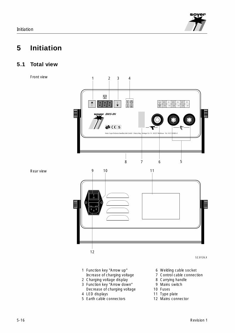
Initiation
5-16
R
Revision 1
5 Initiation
5.1 Total view
Front view
Rear view
1 Function key "Arrow up" 6 Welding cable socketIncrease of charging voltage 7 Control cable connection
2 Charging voltage display 8 Carrying handle3 Function key "Arrow down" 9 Mains switch
Decrease of charging voltage 10 Fuses4 LED displays 11 Type plate5 Earth cable connectors 12 Mains connector
SZ.0126.X
1 2 3 4
678 5
Heinz Soyer Bolzenschweißtechnik GmbH · Etterschlag · Inninger Str. 14 · 82237 Wörthsee · Tel.: 0 81 53/885-0
R BMS-8N
000
TÜV Rheinland
geprüfteSicherheit
S
≈ 70
Ø 3
≈ 100
Ø 4
≈ 115
Ø 5
≈ 140
Ø 6
≈ 175
Ø 7
≈ 190
Ø 8
000
9
12
10 11

Initiation
5-17
R
Revision 1
5.1.1 Operating elements
• Mains switch (item 9, chapter 5.1)The mains switch located at the rear side of the stud welder serves to switchthe stud welder on and off.
• Function key "Arrow up" (item 1, chapter 5.1)The function key "Arrow up" (1) enables continuous increase of the chargingvoltage for larger stud diameters (for setting values, refer to the table).
• Function key "Arrow down" (item 3, chapter 5.1)The function key "Arrow down" (3) enables continuous decrease of thecharging voltage for smaller stud diameters (for setting values, refer to thetable).
5.1.2 Display elements
• Charging voltage display (item 2, chapter 5.1)The digital display shows the adjusted energy value.(charging voltage in volts)
• LED display (item 4, chapter 5.1)The LED display shows the respective operational states.
5.1.3 Connecting elements
• Earth cable connectors (item 5, chapter 5.1)The earth cable connectors serve to connect the earth terminals to the studwelder.
• Welding cable socket (item 6, chapter 5.1) andcontrol cable connection (item 7, chapter 5.1)The control cable connection and the welding cable socket serve to connectthe stud welding pistol to the stud welder.
• Mains connector (item 12, chapter 5.1)The mains connector is located at the rear side of the stud welder.Use the mains cable supplied to connect the stud welder to the powersupply.
4.1 4.2
4.3 4.4
SZ.0127.E
4.1 LED "Malfunction"4.2 LED "Ready"4.3 LED "Release"4.4 LED "Stud on workpiece"
Initiation
5-18
R
Revision 1
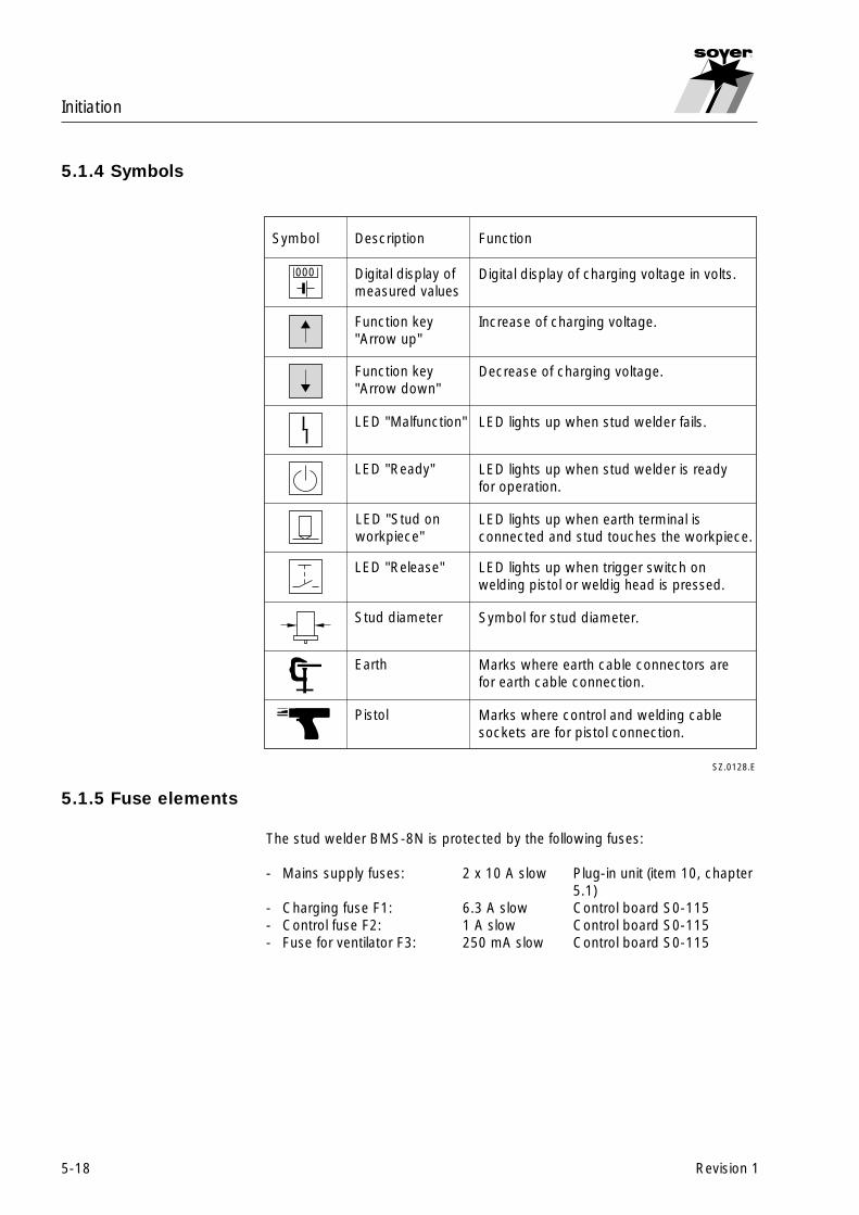
5.1.4 Symbols
5.1.5 Fuse elements
The stud welder BMS-8N is protected by the following fuses:
- Mains supply fuses: 2 x 10 A slow Plug-in unit (item 10, chapter5.1)
- Charging fuse F1: 6.3 A slow Control board S0-115- Control fuse F2: 1 A slow Control board S0-115- Fuse for ventilator F3: 250 mA slow Control board S0-115
Symbol Description Function
Function key"Arrow up"
Increase of charging voltage.
Digital display ofmeasured values
Digital display of charging voltage in volts.
LED "Ready" LED lights up when stud welder is readyfor operation.
LED "Stud onworkpiece"
LED lights up when earth terminal isconnected and stud touches the workpiece.
LED "Release" LED lights up when trigger switch onwelding pistol or weldig head is pressed.
Stud diameter Symbol for stud diameter.
Earth Marks where earth cable connectors arefor earth cable connection.
Pistol Marks where control and welding cablesockets are for pistol connection.
000
SZ.0128.E
Function key"Arrow down"
Decrease of charging voltage.
LED "Malfunction" LED lights up when stud welder fails.

Initiation
5-19
R
Revision 1
� WARNING
Should it become necessary to replace fuses, only use those with specifiedelectrical values. Oversized fuses could either cause defects to the electricalsystem or a fire.
� MORTAL DANGER
Always disconnect the mains plug from the power supply when replacingfuses!
5.2 Preparation for initiation
Connect the stud welding pistol and the earth cables to the stud welder priorto initiation.
5.2.1 Earth connection
• Connect earth cables to earth cable connectors (item 5, chapter 5.1) andlock by turning to the right until stop.
• Connect earth clamps to the workpiece.
Ensure optimum contact with workpiece.☞5.2.2 Connection of stud welding pistol
• Connect welding cable of welding pistol to the welding cable socket (item 6,chapter 5.1) and lock by turning to the right until stop.
• Insert control cable into the control cable socket (item 7, chapter 5.1) andsecure with both locking screws.
• Please observe the connecting instructions (see operating instructions forthe welding pistols).
5.2.3 Mains supply
• Insert mains cable into mains connector (item 12, chapter 5.1) and connectto the power supply.
� MORTAL DANGER
Only connect stud welder to authorized shock-proof sockets.

Initiation
5-20
R
Revision 1
5.3 Operation
• Switch on mains switch.The 4 LED displays (item 4, chapter 5.1) on the front panel of the studwelder shortly light up after switching the stud welder on.
• Select charging voltage by means of function key "Arrow up" (item 1,chapter 5.1) or "Arrow down" (item 3, chapter 5.1) depending on the re-spective stud diameter.
• Position pistol with welding stud on the workpiece.When earth connection is made and the stud in the pistol touches theworkpiece, the LED "Stud on workpiece" (item 4.4, chapter 5.1.2) lights up.
• Press pistol switch. LED "Release" (item 4.3, chapter 5.1.2) lights up andwelding process is released.
Note regarding stud welding pistol PS-1
Pull the trigger handle of the stud welding pistol PS-1 rapidly to be sure torelease a welding process. Please also observe chapter 9.2, Troubleshooting.
Hold the pistol still during the welding process and wait until the☞ welding process has been completed before removing it verticallyfrom the welded stud. A possible operating error e.g. the weldingpistol glides off during welding, is identified by the stud welderand indicated as failure by LED "Malfunction" (item 4.1, chapter5.1.2) lighting up (also refer to chapter 9.1 "Error code").
After removing the welding pistol from the welded stud, the capacitor battery isrecharged. The stud welder is ready for welding again after a few seconds(LED "Ready", item 4.2, chapter 5.1.2, lights up).
5.4 Welding parameters
The welding parameters of the stud welder BMS-8N were determined byusing the stud welding pistols PS-1 and PS-1K.
The charging voltages shownin the table on the right arestandard values. They varyfrom the stated settingdepending on the materialtype, workpiece thicknessand surface condition of theworkpiece.
SZ.0129.X
≈ 70
Ø 3
≈ 100
Ø 4
≈ 115
Ø 5
≈ 140
Ø 6
≈ 175
Ø 7
≈ 190
Ø 8
000

6-21
Quality control
R
Revision 1
6 Quality control
6.1 General
The 0905 DVS Guideline, part 2, of April 1979 is applicable with regard toquality assurance of stud weld joints. The tests described in this section arewritten in simplified terms, following above regulation. They refer to work teststhat are carried out and supervised by the user prior to and during welding.
Heinz Soyer Bolzenschweißtechnik GmbH is a member of the German WeldingSociety (DVS = Deutscher Verband für Schweißtechnik e.V), Munich.
6.2 Demands on the company
The company must employ a technical supervisor responsible for weldingmatters, as well as qualified operating personnel for stud welding (see DVSGuideline 0905, part 2, section 4).
6.3 Proof of qualification
In the case of components which documentation must be provided for, or studwelding works which as per DIN 4100, DIN 4113 are subject to acceptance,the processing company must submit a certificate of competence or a proof ofqualification for working with stud welding equipment (see DVS Guideline 0905,part 2, sections 4.1 and 4.2). The proof of qualification applies in particular tothe fastening of structures that are relevant in terms of safety regulations. Whenbeing used in the building industry, only approved base and stud materialsmay be used (for example, see DIN 4100, section 2.1, certificate of approvalfor stainless steel ifBT; DIN 4113, part 2).
6.4 Type and scope of test
Provided that the SOYER stud welding system is properly used and thematerials are appropriately selected, the strength of the welding joint (weldingzone) will always be stronger than that of the stud or base material. The follow-ing tests are carried out in general practice:
• Standard work test (see DVS Guideline 0905, part 2, section 5.1.2)
• Simplified work test (see DVS Guideline 0905, part 2, section 5.1.2)
Quality control
6-22
R
Revision 1
6.4.1 Standard work test
Generally, standard work tests have to be carried out and supervised by theuser before welding at a structure and after a certain number of welds hasbeen made. The number of welds after which a standard work test is requiredis agreed upon with the customer.
The standard work test is restricted to the stud diameter, base material andtype of equipment used. It comprises the following tests:
• Visual inspection (all samples)
• Tensile test (at least 3 samples )
• Bend test (at least 3 samples)
In case of doubt, the test scope should be extended in compliance with DVSGuideline 0905, part 2, section 5.1.1.
6.4.2 Simplified work test
Simplified work tests serve to check the correct setting and function of theequipment. They are carried out at the beginning of every working shift andafter several hours of interruption.
Simplified work tests include:
• Visual inspection (all samples)
• Bend test (all samples)
6.5 Test execution
6.5.1 Production of samples
The studs for the work test are welded on a sheet metal the minimum size ofwhich is 700 mm x 200 mm. Use the same welding positions and edge dis-tances as on the component to be welded later. If it is possible and sensiblefrom an economical point of view, use parts that are identical to those used inlater production.
6.5.2 Visual inspection
The visual inspection serves as a rough check for major defects. The uniformityof the weld is assessed. When in doubt, tensile and bend tests should becarried out.
6-23
Quality control
R
Revision 1
6.5.3 Tensile test
The tensile test serves to test the metallic bond of the stud with the basemetal. At least 3 studs are welded and then axially loaded by means of anappropriate tension device until they break. If the customer demands that acertain percentage of the welded studs should be tested with a specific testload in production, a tension device with load indicator should be used.
If the stud breaks outside the welding zone, the test is regarded as successful.If it breaks within the welding zone, however, the fractured surface must beexamined. The unwelded surface may not exceed a maximum of 20 % of thewelding surface. When in doubt, the breaking load in accordance with DIN267, part 3, should be determined.
If the quantity of defective studs in one random test exceeds the acceptancenumber specified in DIN 267, part 5, as per AQL 4, it is necessary to find outthe reason for the faults. The setting values must be modified and the testrepeated.
6.5.4 Bend test
The bend test is a simple work test which serves to roughly check the settingvalues selected. The welding zone is subjected to undefined tension, pressureand bending. A minimum of 3 studs is welded and bent to an angle of 30° bymeans of a tube that is slipped over the stud. The test is considered as suc-cessful, if no superficial fissure or fracture is detected in the welding zone. Theacceptance number in accordance with DIN 267, part 5, as per AQL 4 must becomplied with. If the quantity of defective parts in one inspection lot exceedsthe acceptance number AQL 4 (see DIN 267), the cause of trouble must bedetermined and the test repeated again.

7-24
Maintenance
R
Revision 1
7 Maintenance
7.1 Stud welder
The stud welder is constructed in such a way that only a minimum of mainte-nance is required. The interior of the stud welder should, however, be cleanedat regular intervals depending on the environmental conditions at the locationof use. Any defects of the system's control part can easily be eliminated byreplacing the printed circuit board and/or the clearly arranged fuses.
� MORTAL DANGER
Before replacing any components, disconnect the mains cable from themains supply. Electric and electronic components may only be replaced bya specialist. Contact the SOYER® service department if necessary.
7.2 Replacement of components
Defective components may only be replaced by trained SOYER servicemen.Perfect function of your stud welder can only be guaranteed when originalSOYER spare parts are used.
� MORTAL DANGER
Ensure that the capacitors are discharged before replacing any compo-nents.

Maintenance
7-25
R
Revision 1
7.3 Fuses
The stud welder BMS-8N is protected by the following fuses:
- Mains supply fuses: 2 x 10 A slow Plug-in unit (item 10, chapter5.1)
- Charging fuse F1: 6.3 A slow Control board S0-115- Control fuse F2: 1 A slow Control board S0-115- Fuse for ventilator F3: 250 mA slow Control board S0-115
� DANGER TO HEALTH
Should it become necessary to replace fuses, only use fuses with thespecified electrical values. Oversized fuses could either cause defects tothe electrical system or a fire.
� MORTAL DANGER
Disconnect the mains plug from the mains supply when replacing fuses.
Spare parts
8-26
R
Revision 1
8 Spare parts
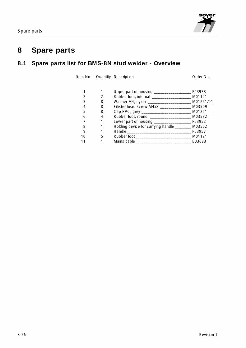
8.1 Spare parts list for BMS-8N stud welder - Overview
Item No. Quantity Description Order No.
1 1 Upper part of housing __________________ F039382 2 Rubber foot, internal ___________________ M011213 8 Washer M4, nylon _____________________ M01251/014 8 Fillister head screw M4x8 _______________ M035095 8 Cap PVC, grey ________________________ M012516 4 Rubber foot, round ____________________ M035827 1 Lower part of housing __________________ F039528 1 Holding device for carrying handle ________ M035629 1 Handle _______________________________ F03957
10 5 Rubber foot___________________________ M0112111 1 Mains cable___________________________ E03683

Spare parts
8-27
R
Revision 1
8.2 Exploded view of BMS-8N stud welder - Overview
C
A
B
D
SZ.0174.X
12
34 5
6
7
8
9
10
11

Spare parts
8-28
R
Revision 1
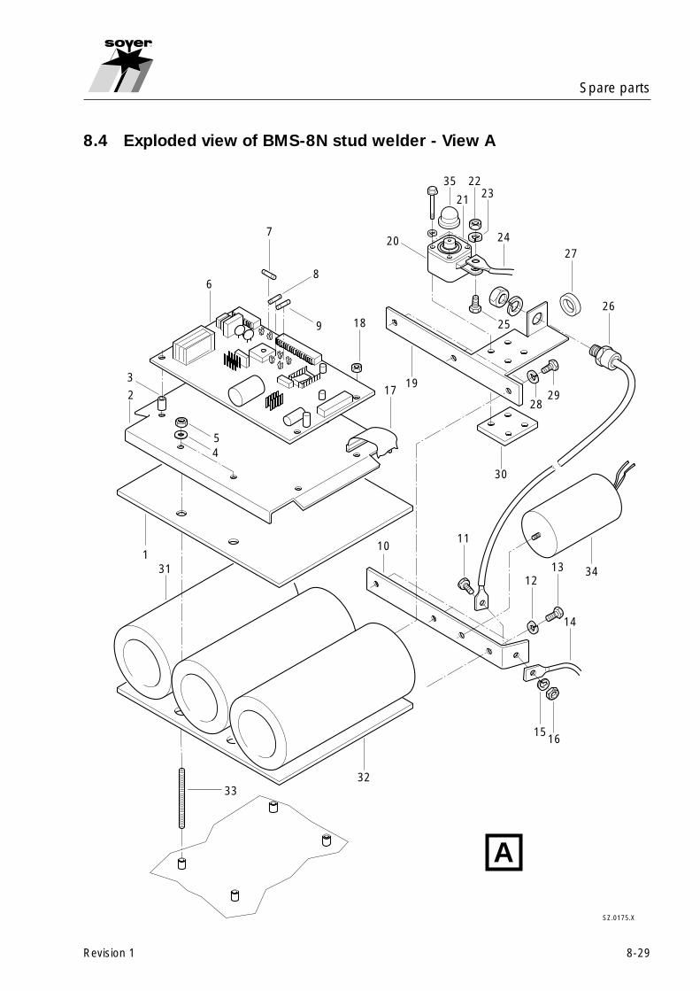
8.3 Spare parts list for BMS-8N stud welder - View A
Item No. Quantity Description Order No.
1 1 Rubber mat ___________________________ F039512 1 Capacitor mounting plate _______________ F039493 4 Spacing bolt M4x10 ___________________ M035534 4 Spring ring M4 ________________________ M010745 4 Hexagon nut M4 ______________________ M010126 1 PC Board SO-115, revision 2 ____________ F04295/FA7 1 Fine-wire fuse 6.3AT ___________________ E018978 1 Fine-wire fuse 1AT _____________________ E018929 1 Fine-wire fuse 0.25AT __________________ E03535
10 1 Busbar - _____________________________ F0222611 1 Hexagon head cap screw M8x16 ________ M0112912 3 Spring ring M5 ________________________ M0107513 3 Hexagon head cap screw M5x12 ________ M0111714 1 Cable harness 160 mm _________________ F03947/FA-E15 1 Spring ring M8 ________________________ M0107716 1 Hexagon nut M8 ______________________ M0101517 1 Flat cable 26-pole _____________________ F03851/FA-E18 4 Synthetic nut M4 ______________________ M0353819 1 Busbar + _____________________________ F0429720 1 Thyristor clamping cap _________________ E0198721 1 Thyristor S30E4A ______________________ E0136122 1 Hexagon nut M8 ______________________ M0101523 1 Spring ring M8 ________________________ M0107724 1 Cable harness 160 mm _________________ F03947/FA-E25 1 Hexagon head cap screw M8x16 ________ M0112926 1 Diode SKR 130/16_____________________ E0120327 1 Toroidal core, coated __________________ E0360728 3 Spring ring M5 ________________________ M0107529 3 Hexagon head cap screw M5x12 ________ M0111730 1 Thyristor mounting plate ________________ F0359331 3 Capacitor 22000µF ____________________ E0119932 1 Rubber mat ___________________________ F0395033 4 Threaded rod M4x85 mm _______________ M0124434 1 Charging module ______________________ E0379535 1 Protecting cap (R 1/2") _________________ M03641
Spare parts
8-29
R
Revision 1
8.4 Exploded view of BMS-8N stud welder - View A
A
SZ.0175.X
1
2
3
45
6
7
8
9
17
18
31
3233
1011
1213 34
14
1516
19
20
21
223523
24
25
26
27
2829
30

Spare parts
8-30
R
Revision 1
8.5 Spare parts list for BMS-8N stud welder - View B, C and D
Item No. Quantity Description Order No.
1 2 Flat head screw M3x10 _________________ M013482 1 Mains switch __________________________ E036853 1 Varistor ______________________________ E013474 1 Coated toroidal core, large ______________ E036075 1 Coated toroidal core, medium-sized ______ E036356 1 Rear panel of housing __________________ F039397 4 Washer M4 ___________________________ M010628 1 Fan 24VDC ___________________________ E036849 2 Spring ring M3 ________________________ M01073
10 2 Hexagon nut M3 ______________________ M0101111 4 Tooth lock washer M4 __________________ M0122112 4 Hexagon nut M4 ______________________ M0101213 1 Cheese-head screw M6x70 _____________ M03584
13.1 1 Spring ring M6 ________________________ M0107614 1 Washer M6 ___________________________ M0170715 1 Toroidal mains transformer ______________ E0368916 4 Synthetic nut M4 ______________________ M0353817 1 PC Board SO-105, revision 1 ____________ F03941/FA18 2 Slotted screw M3x6 ____________________ M0100119 2 Spring ring M3 ________________________ M0107320 4 Spacing bolt M4x20, synthetic ___________ M0355022 1 Panel jack 15-pole _____________________ E0371423 1 Copper bar ___________________________ F0394224 2 Hexagon nut M4 ______________________ M0101225 2 Spring ring M4 ________________________ M0107426 1 Wire resistor 22R ______________________ E0288127 1 Wire resistor 3.9R _____________________ E0368728 4 Resistor mounting plate ________________ F0129629 4 Distance sleeve 7x1.4x10mm ___________ M0126130 1 Front panel ___________________________ F03944/FA31 2 Earth connector SEM-25 _______________ E0196432 1 Earth socket BEM-25 __________________ E0195833 2 Spacing bolt UNC 4-40 _________________ M03576

Spare parts
8-31
R
Revision 1
8.6 Exploded view of BMS-8N stud welder -View B, C and D
B
D
C
SZ.0176.X
1 2
3
45
6
7
8
910
1211
13
13.1
14
15
16
17
18 19
20
2223
2425
26 27
28
29
30
31
3233
Malfunctions
9-32
R
Revision 1
9 Malfunctions
The following list of errors, their causes and remedies is designed to help youeliminate any trouble immediately on the spot. If it is difficult or impossible toeliminate the trouble, please contact the SOYER customer service responsiblefor your area or Heinz Soyer Bolzenschweißtechnik GmbH. For address andtelecommunication data, please refer to chapter 1.6, page 1-4.
� MORTAL DANGER
Always disconnect the connecting plug from the mains socket before open-ing the housing of the stud welding system. Only trained and appropriatelyqualified personnel are allowed to carry out works on the electric powersupply and stud welder.
� WARNING
Only trained and appropriately qualified personnel are allowed to replacecomponents of the stud welding system.
� MORTAL DANGER
Before replacing components, ensure that the capacitors are discharged.

Malfunctions
9-33
R
Revision 1
9.1 Error codes
The stud welder switches off when malfunctions occur. The charging voltage ofthe capacitors is internally discharged. An error message appears as code onthe charging voltage display (item 2, chapter 5.1):
Error code Description Possible cause
E-1 Safety circuit activated Welding operating errorE-2 Charging duration exceeded Charging fuse defectiveE-3 Internal error Safety circuit defectiveE-4 Mains voltage not in order Mains voltage deviation
too large115/230 V AC+ 10 % - 15 %
The error message is acknowledged by switching the stud☞ welder off and then switching it on again. If the error messageappears again, please inform the customer service responsiblefor your area.
E-5 Excess temperature of transformer Excessive welding cycle
If the error message E-5 appears, please do not switch off the☞ stud welder. The stud welder is ready for welding again after ithas cooled down.
E-6 Software fault or hardware failure→ Elimination by SOYER customer service only
E-7 Hardware failure in charging circuit→ Elimination by SOYER customer service only

Malfunctions
9-34
R
Revision 1
Error Cause→ Elimination
System does not weld, System is not switched onno sparking → Switch on system, LED “Ready” and charging voltage display must light up
Welding cable or control cable are not connected properly or damaged→ Connect cables properly or check for damage. Replace if necessary
Both earth cables are not connected or are not properly connected and/orearth clamps are not attached to the workpiece.→ Connect earth cables, attach earth clamps to the workpiece
Welding points and/or earth connection points at the workpiece are notmetallically blank→ Prepare workpiece and/or studs
System is switched on, Mains supply is defectivebut does not function → Check mains supply fuse
Fuse of stud welder is defective→ Replace defective fuse (see chapter 7.3)
There is no arc even though Stud without ignition tip or centre mark too deep for the ignition tipsystem is ready for operation → Use stud with ignition tip or reduce centre mark
Control of stud welder or welding pistol is defective→ Inform SOYER customer service
Stud is too loose in stud holder→ Press stud holder together or tighten it
Stud thread scorched Stud holder worn→ Replace stud holder
Varying welding results Welding energy not correctly adjusted→ Adjust welidng energy
Cable connections are too loose. Transition resistances are generated→ Check all cable connections and earth clamps for tight fit.
Stud too loose or not fully inserted into stud holder until stop→ Insert stud into stud holder until stop. If necessary, replace stud holder
Varying welding results Magnetic blowing action. Arc is forced into a certain direction→ Alter earth clamp fixture, place iron parts on the edges and/or rotate
welding pistol
9.2 Troubleshooting

Malfunctions
9-35
R
Revision 1
Error Cause→ Elimination
Intensive sparking, Welding energy is set too highstud flange almost → Reset welding energymelted away
Stud not welded with total Welding energy is set too lowflange surface, deficient → Reset welding energyweld joint strength
Poor earth connection→ Check earth cables and earth clamps for tight fit, tighten if necessary
Workpiece surface too soiled→ Clean workpiece surface
Stud weld base deformed→ Use new welding studs
Stud projection over stud holder incorrectly set→ Set projection to 2-3 mm (distance between stud holder and stud weld
base)
Spring pressure incorrectly set→ Set spring pressure
Welding pistol in tilted position→ Ensure that all 3 pistol legs are simultaneously and evenly positioned on the
workpiece
Base metal not weldable→ Use suitable material combinations
System does not weld Release period of 0.6 sec. exceeded after pressing the pistol trigger switch→ Trigger handle of welding pistol PS-1 too slowly pulled→ Pistol trigger switch incorrectly set or defective→ Welding pistol mechanically defective (e.g. jammed or sluggish piston)
Release periodFor safety and welding quality reasons, the ignition tip of the welding stud musttouch the workpiece and be ignited within 0.6 sec. after pressing the pistoltrigger switch. The welding process is not released when exceeding this periodof time.

10-36
Transport and storage
R
Revision 1
10 Transport and storage
The stud welder is sturdily designed and has a two-piece metal case with frontand rear panel. Owing to the electronic components, however, please ensurethat transport is free from vibrations.
The stud welder BMS-8N is equipped with a carrying handle for easy transport.
The unit suitcase GK-2 is the optimum solution for storing and transporting thestud welder BMS-8N and the stud welding pistol PS-1K.
Prevent unauthorized use of the stud welding system by children and unquali-fied personnel.After long system standstill, we recommend having the stud welder checkedby SOYER® servicemen prior to initiation.
The housing of stud welder BMS-8N corresponds to safety class☞ IP 21. Please observe e.g. that this system of protection is notsuitable for being operated or transported in the rain.

11-37
Standards and guidelines
R
Revision 1
11 List of standards and guidelines
• 91/368/EEC EC Directive on Machinery(formerly 89/392 EEC)
• 73/23/EEC EC Directive on Low Voltage
• 93/31/EEC EC Directive on Electromagnetic(formerly 89/336/EEC) Compatibility
• EN 292 - 1 Safety of machinery;basic terms, general principles of construction; basic terminology,systems engineering
• EN 292 - 2 Technical principles, specifications
• EN 60204 -1 Electric equipment of machinery, general(formerly VDE 0113) requirements
• EN 60974 - 1 Safety requirements for arc weldingequipment, part 1 welding current sources
• EN 292-2 Operating instructions
• VGB 1 General instructions(instructions for accident prevention)
• VBG 5 Power-operated equipment(instructions for accident prevention)
• DIN 4100 Welded steel structures with predominantlydead load
• DIN 267, part 5 Screws, nuts and the like, technical terms ofdelivery, testing and acceptance
• DIN 17100 Constructional steels - general types, qualitystandard
• DIN EN ISO 14555 Arc welding of metallic materials
• DIN EN ISO 13918 Studs and ceramic ferrules for arc welding
• DIN 50049 Certificate on material tests
• DIN 50125 Testing of metallic materials, tensile tests,guidelines for production
• DIN 54111, part 1 Non-destructive method of testing
• DVS Leaflet 0902 Arc welding with retract ignition
• DVS Guideline 0905, part 1 Quality assurance of stud welding joints

12-38
Terms of warranty
R
Revision 1
12 Terms of warranty
We warrant for this equipment for a period of 6 months in accordance with ourconditions of sale and delivery.
Any claim to a warranty will be forfeited if damage is caused by improperoperation, or if repairs or interferences have been made by unauthorizedpersons, or whenever accessories and spare parts have been used which donot match our equipment.
We cannot guarantee the quality of welding joints if welding studs acquiredfrom another company are used.

A-1
R
Revision 1
1 Adjustment of stud welding pistol
1.1 Adjustment of stud holder
The stud holders of stud welding pistols PS-1, PS-3K, PS-0K and PS-1K areall of the same style. When using long welding studs with the welding pistolsPS-0K and PS-1K, however, it is necessary to shorten the stud holders' stopscrew (4) due to these pistols' small size.
For pistols PS-1, PS-3K, PS-0K and PS-1K, use the standard☞ stud holder of 40 mm length with adjusting screw!Ensure that the maximum stud length does not exceed 35 mm.
1 Stud 3 Lock nut2 Stud holder 4 Stop screw
Different stud holders are required for different stud diameters.
Adjust the stud holder as follows:
• Loosen lock nut (3)
• Insert stud (1) into stud holder.The top edge of the stud flange must project for about 1.5 mm from thefront edge of the stud holder.
The stud must come into contact with the stop screw (4).☞• Adjust stop screw (4) in the stud holder by turning it until the distance from
the top edge of the stud flange to the front edge of the stud holder is 1.5mm.
• Secure stop screw (4) by means of lock nut (3)
Appendix A/PS-1 and PS-1KAdjustment of stud welding pistols - Tip ignition
1 2 3 4
1,5
SZ.0138.X

A-2
R
Revision 1
1.2 Installation of stud holder into stud welding pistolsPS-1 and PS-3K
The illustration below shows how to install the stud holder into the stud weldingpistols PS-1 and PS-3K.
1 Pistol leg 4 Bellows2 Stud holder 5 Spring piston3 Sleeve nut 6 Stud flange
• Loosen sleeve nut (3) by means of socket wrench SW 17.
• Insert stud holder (2) into spring piston (5) until it stops.
• Tighten stud holder (2) by means of the sleeve nut (3).
The stud flange must project beyond the top of the pistol legs or☞ the support tube for the thickness of the flange. If need be,remove stud holder and correct the projection by means of thestop screw.
Appendix A/PS-1 and PS-1KAdjustment of stud welding pistols - Tip ignition
1
6
2 3 5
SZ.0136.X
4

A-3
R
Revision 1
1.3 Installation of stud holder into stud welding pistolPS-1K and PS-0K
The illustration below shows how to install the stud holder into the stud weldingpistol PS-1K. These instructions are also applicable for stud welding pistolPS-0K.
1 Stud holder2 Support tube
• Loosen sleeve nut by means of socket wrench SW 14 .
• Insert stud holder (1) into spring piston until it stops.
• Tighten stud holder (1) by means of the sleeve nut. Remove the support tube (2) to easily install the stud holder.
The stud flange must project beyond the top of the pistol legs or☞ the support tube for the thickness of the flange. If need be,remove the stud holder and correct the projection by means ofthe stop screw.
Appendix A/PS-1 and PS-1KAdjustment of stud welding pistols - Tip ignition
PS-1K
SZ.0133.E
1 2
Stud flange

A-4
R
Revision 1
1.4 Adjustment of spring pressure
The pressure with which the stud is pressed against the workpiece during thewelding process is called spring pressure.
The illustration below shows how to adjust the spring pressure of stud weldingpistol PS-1 which is equipped with a spring pressure indicator. The studwelding pistol PS-3K is equipped with a similar spring pressure indicator. Thewelding pistols PS-0K and PS-1K do not have a spring pressure indicator.
1 Adjusting screw2 Spring pressure indicator
The spring pressure for all stud welding pistols described here is adjusted bymeans of the adjusting screw (1). The adjusted spring pressure is indicated onthe spring pressure scale (2). Adjust the spring pressure as follows:
• Turn adjusting screw (1) to the left until stopIndicator position 1 = low pressure
• Turn adjusting screw (1) 3.5 turns to the rightIndicator position 2 = medium pressure
• Turn adjusting screw (1) to the right until stopIndicator position 3 = strong pressure
The adjustment of spring pressure depends on the material of both the weldingstud and the workpiece.
Before starting work, carry out some experimental welds and test them to findout the optimum adjustment.
Several samples have to be taken during production to ensure constantly goodwelding results (see DVS Guideline 0905, part 2, "Quality assurance of studwelding joints").
Appendix A/PS-1 and PS-1KAdjustment of stud welding pistols - Tip ignition
SZ.0137.E
3 2 1
Federdruck
21

A-5
R
Revision 1
2 Initiation
2.1 Total view
The illustration below shows stud welding pistol PS-3K. The indicated compo-nents are only slightly different from those of stud welding pistols PS-1, PS-3,PS-0K and PS-1K.
• The stud welding pistols PS-0K and PS-1K are equipped with support tubesinstead of pistol legs (2).
• The stud welding pistols PS-0K and PS-1K are not equipped with a springpressure indicator. The stud welding pistol PS-1K is optionally available with3 pistol legs.
1 Sleeve nut 5 Connecting cable2 Pistol leg 6 Push-button3 Spring pressure indicator 7 Stud holder4 Adjusting screw for spring pressure
Appendix A/PS-1 and PS-1K - Initiation - Tip ignition
R
PS-3K
SZ.0135.X
1 2 3
4
5
6
7
A-6
R
Revision 1
2.2 Connecting stud welding pistols to stud welder
The stud welding pistols are connected to the stud welder by means of pistoland control cables.
2.3 Operation
• Connect stud welder to earth
• Connect stud welding pistol as described in chapter 5
• Adjust welding pistol as described in Appendix A, Chapter 1
• Connect stud welder to the mains supply
• Adjust stud welder for the welding studs to be used
• Insert welding stud into stud holder
• Position stud welding pistol on the workpiece and press push-button
Appendix A/PS-1 and PS-1K - Initiation - Tip ignition

A-7
R
Revision 1
3 Spare parts
Appendix A/PS-1 and PS-1K - Spare parts - Tip ignition

A-8
R
Revision 1
3.1 Spare parts list for stud welding pistol PS-1K
Item Quantity Description Order No.
1 1 Support tube Ø 30 mm _________________ F038131.1 3 Pistol leg (optional) _____________________ F038901.2 3 Grub screw (optional) __________________ M01338
2 1 Support tube retainer __________________ F038123 2 Grub screw M6 x 5 ____________________ M035414 3 Grub screw with spring M4 x 10 _________ M035425 1 Insulating ring _________________________ F038236 1 Sleeve nut ____________________________ F014697 1 Bellows ______________________________ F029898 1 Working piston ________________________ F038159 1 Grub screw M4 x 6 ____________________ M01315
10 3 Cheese-head screw____________________ M0199811 1 Pistol half-shell, small
(contained in item 19) __________________ not numbered12 1 Push-button, 1-pole ___________________ E0210313 1 Cap, PVC ____________________________ E0210414 1 Ball bearing bush ______________________ F0382415 1 Pistol label PS-1K _____________________ M0204216 1 Pistol label, company address ___________ M0160117 1 Cylindrical pin Ø 6 x 36 _________________ M0359418 2 Flat-head screw M3 x 6 ________________ M0156119 1 Complete pistol housing ________________ F03811/FA20 3 Insert nut M4 x 6 ______________________ M0180921 1 Spring retainer ________________________ F0381422 1 Pressure spring _______________________ F0389123 1 Adjustable adapter _____________________ F0239724 1 Grub screw M4 x 8 ____________________ M0133325 1 Locking ring __________________________ M0137426 1 Split taper socket ______________________ F0240227 1 Grub screw M4 x 6 ____________________ M0131528 1 PVC pin ______________________________ F0312829 1 Adjusting screw _______________________ F0172930 1 Earth cable complete (stranded conductor) F02405/FA31 1 Strain relief ___________________________ F0171532 1 Cheese-head screw M4 x 10 ____________ M0108733 1 Spring washer M4 _____________________ M0107434 1 PVC clip _____________________________ M0138735 1 Grub screw M5 x 8 ____________________ M0133736 1 Grub screw M8 x 8 ____________________ M0210837 1 Anti-kink sleeve _______________________ E0234938 1 Control cable complete with plug ________ E0210139 1 Pistol cable complete with plug __________ F01100/FA
comprising1 Earth connector SKM-25 _______________ E01963
3 m Earth cable 25 mm2 __________________________E02035
Appendix A/PS-1 and PS-1K - Spare parts - Tip ignition

A-9
R
Revision 1
3.2 Exploded view of stud welding pistol PS-1K
Appendix A/PS-1 and PS-1K - Spare parts - Tip ignition
PS -1
K
R
1
12
15
14
17
1813
102
3
SZ.0177.X
3
4
56
7
8
9
1124
27
28
29
16
19
21
22
30203233
3437
3635
31
23
2526
18
38
39
1.11.2

A-10
R
Revision 1
Appendix A/PS-1 and PS-1K - Spare parts - Tip ignition

Beiblatt zu BMS-8N/2 / Supplement to BMS-8N/2
R
Änderung der Netzspannung auf 115 / 230 Volt
Alteration of mains voltage to 115 / 230 volt
LEBENSGEFAHRZiehen Sie vor dem Öffnen des Gehäuses der Bolzenschweißanlage grundsätzlichden Anschlussstecker aus der Netzanschlussdose. Nur ausgebildetes undentsprechend qualifiziertes Personal darf Arbeiten an der elektrischenStromversorgung und Anlage durchführen.
MORTAL DANGERAlways disconnect the connecting plug from the mains supply socket before openingthe housing of the stud welding equipment. Only trained and appropriately qualifiedpersonnel are allowed to carry out works on the electric power supply and stud welder.
F1 6.3AT
Steuerplatine SO-115 Rev. 3 (SMD)Control printed circuit SO-115 Rev. 3
F3 2
50m
A
F2 1
AT
F4 10AT
F7 10AT
Steuerplatine SO-115 Rev. 3 (SMD)Control printed circuit SO-115 Rev. 3
F1 6.3AT
F3 2
50m
A
F2 1
AT
F5 10AT
F6 10AT
F4 115 V
F7 115 V
F5 230 V
F6 230 V
Netzspannung / Line voltage 115 Volt AC
Sicherung 10AT in Sicherungshalter F4 und F7 einsetzen.
Netzspannung / Line voltage 230 Volt AC
Sicherung 10AT in Sicherungshalter F5 und F6 einsetzen.
setting 115V AC setting 230V AC
Insert fuse 10AT into F4 and F7 fuse holders Insert fuse 10AT into F5 and F6 fuse holders
No. F04538/FA No. F04538/FA

Heinz SoyerBolzenschweißtechnik GmbHEtterschlagInninger Straße 14D-82237 WörthseeTel.: ++49-(0) 81 53 / 8 85-0 Fax: ++49-(0) 81 53 / 80 30Internet: www.soyer.de
www.soyer.comE-Mail: [email protected]