operating instructions multichannel charge amplifier type...
TRANSCRIPT

Operating Instructions
Multichannel Charge Amplifier
Type 5019B…
002-124Be-11.98 (B11.5019Be) kISTLER
Page 1 ... 67
Your Competent Distributor:
Kistler Instrumente AG Winterthur, CH-8408 Winterthur, Schweiz Tel. + 41 52 83 11 11, Fax + 41 52 25 72 00

Multichannel Charge Amplifier Type 5019B…
B11.5019Be-11.98kISTLER
Page 2

Contents
1 Introduction ÷÷÷÷÷÷÷÷÷÷÷÷÷÷÷÷÷÷÷÷÷÷÷÷÷÷÷÷÷÷÷÷÷÷÷÷÷÷÷÷÷÷÷÷÷÷÷÷÷÷÷÷÷÷÷÷ 5
2 Important guidelines÷÷÷÷÷÷÷÷÷÷÷÷÷÷÷÷÷÷÷÷÷÷÷÷÷÷÷÷÷÷÷÷÷÷÷÷÷÷÷÷÷÷÷÷÷÷÷÷÷÷÷÷ 6
2.1 For your safety ÷÷÷÷÷÷÷÷÷÷÷÷÷÷÷÷÷÷÷÷÷÷÷÷÷÷÷÷÷÷÷÷÷÷÷÷÷÷÷÷÷÷÷÷÷÷÷÷÷÷÷ 62.2 Fundamental precautions, mains power switchover ÷÷÷÷÷÷÷÷÷÷÷÷÷÷÷÷÷÷÷÷÷÷ 72.3 Electromagnetic Compatibility ÷÷÷÷÷÷÷÷÷÷÷÷÷÷÷÷÷÷÷÷÷÷÷÷÷÷÷÷÷÷÷÷÷÷÷÷÷÷÷ 82.4 Tips for using these instructions ÷÷÷÷÷÷÷÷÷÷÷÷÷÷÷÷÷÷÷÷÷÷÷÷÷÷÷÷÷÷÷÷÷÷÷÷÷ 9
3 General description of the amplifier ÷÷÷÷÷÷÷÷÷÷÷÷÷÷÷÷÷÷÷÷÷÷÷÷÷÷÷÷÷÷÷÷÷÷÷÷÷÷÷ 10
3.1 Different variants ÷÷÷÷÷÷÷÷÷÷÷÷÷÷÷÷÷÷÷÷÷÷÷÷÷÷÷÷÷÷÷÷÷÷÷÷÷÷÷÷÷÷÷÷÷÷÷÷÷ 103.2 Options ÷÷÷÷÷÷÷÷÷÷÷÷÷÷÷÷÷÷÷÷÷÷÷÷÷÷÷÷÷÷÷÷÷÷÷÷÷÷÷÷÷÷÷÷÷÷÷÷÷÷÷÷÷÷÷÷ 103.2.1 Charge amplifier on Euro-Card Type 5059 ÷÷÷÷÷÷÷÷÷÷÷÷÷÷÷÷÷÷÷÷÷÷÷÷÷÷÷÷ 103.2.2 A/D converter board for signal display Type 5261÷÷÷÷÷÷÷÷÷÷÷÷÷÷÷÷÷÷÷÷÷÷÷÷ 11
4 Technical data, Functional description÷÷÷÷÷÷÷÷÷÷÷÷÷÷÷÷÷÷÷÷÷÷÷÷÷÷÷÷÷÷÷÷÷÷÷÷÷ 12
4.1 Introduction ÷÷÷÷÷÷÷÷÷÷÷÷÷÷÷÷÷÷÷÷÷÷÷÷÷÷÷÷÷÷÷÷÷÷÷÷÷÷÷÷÷÷÷÷÷÷÷÷÷÷÷÷÷ 124.2 Function of the multichannel charge amplifier Type 5019B÷÷÷÷÷÷÷÷÷÷÷÷÷÷÷÷÷ 124.2.1 Block diagram ÷÷÷÷÷÷÷÷÷÷÷÷÷÷÷÷÷÷÷÷÷÷÷÷÷÷÷÷÷÷÷÷÷÷÷÷÷÷÷÷÷÷÷÷÷÷÷÷÷÷÷ 124.2.2 Digital input "Remote Operate" ÷÷÷÷÷÷÷÷÷÷÷÷÷÷÷÷÷÷÷÷÷÷÷÷÷÷÷÷÷÷÷÷÷÷÷÷÷÷ 144.2.3 Power supply ÷÷÷÷÷÷÷÷÷÷÷÷÷÷÷÷÷÷÷÷÷÷÷÷÷÷÷÷÷÷÷÷÷÷÷÷÷÷÷÷÷÷÷÷÷÷÷÷÷÷÷÷ 154.3 Functional principle of the charge amplifier unit÷÷÷÷÷÷÷÷÷÷÷÷÷÷÷÷÷÷÷÷÷÷÷÷÷÷ 164.3.1 Block diagram ÷÷÷÷÷÷÷÷÷÷÷÷÷÷÷÷÷÷÷÷÷÷÷÷÷÷÷÷÷÷÷÷÷÷÷÷÷÷÷÷÷÷÷÷÷÷÷÷÷÷÷ 164.3.2 Input stage with range selection ÷÷÷÷÷÷÷÷÷÷÷÷÷÷÷÷÷÷÷÷÷÷÷÷÷÷÷÷÷÷÷÷÷÷÷÷÷ 174.3.3 Digital voltage divider (12-bit DAC) ÷÷÷÷÷÷÷÷÷÷÷÷÷÷÷÷÷÷÷÷÷÷÷÷÷÷÷÷÷÷÷÷÷÷÷ 184.3.4 Zero compensation ÷÷÷÷÷÷÷÷÷÷÷÷÷÷÷÷÷÷÷÷÷÷÷÷÷÷÷÷÷÷÷÷÷÷÷÷÷÷÷÷÷÷÷÷÷÷÷ 184.3.5 Low-pass filter ÷÷÷÷÷÷÷÷÷÷÷÷÷÷÷÷÷÷÷÷÷÷÷÷÷÷÷÷÷÷÷÷÷÷÷÷÷÷÷÷÷÷÷÷÷÷÷÷÷÷÷ 194.3.6 Microprocessor control and monitoring ÷÷÷÷÷÷÷÷÷÷÷÷÷÷÷÷÷÷÷÷÷÷÷÷÷÷÷÷÷÷÷÷ 194.4 Display, controls and connections ÷÷÷÷÷÷÷÷÷÷÷÷÷÷÷÷÷÷÷÷÷÷÷÷÷÷÷÷÷÷÷÷÷÷÷÷ 194.4.1 Display ÷÷÷÷÷÷÷÷÷÷÷÷÷÷÷÷÷÷÷÷÷÷÷÷÷÷÷÷÷÷÷÷÷÷÷÷÷÷÷÷÷÷÷÷÷÷÷÷÷÷÷÷÷÷÷÷ 204.4.2 Control ÷÷÷÷÷÷÷÷÷÷÷÷÷÷÷÷÷÷÷÷÷÷÷÷÷÷÷÷÷÷÷÷÷÷÷÷÷÷÷÷÷÷÷÷÷÷÷÷÷÷÷÷÷÷÷÷ 214.4.3 Connections, view or rear plate ÷÷÷÷÷÷÷÷÷÷÷÷÷÷÷÷÷÷÷÷÷÷÷÷÷÷÷÷÷÷÷÷÷÷÷÷÷÷ 24
5 Assembly, installation and first commissioning ÷÷÷÷÷÷÷÷÷÷÷÷÷÷÷÷÷÷÷÷÷÷÷÷÷÷÷÷÷ 25
5.1 General information ÷÷÷÷÷÷÷÷÷÷÷÷÷÷÷÷÷÷÷÷÷÷÷÷÷÷÷÷÷÷÷÷÷÷÷÷÷÷÷÷÷÷÷÷÷÷÷ 255.2 Connecting÷÷÷÷÷÷÷÷÷÷÷÷÷÷÷÷÷÷÷÷÷÷÷÷÷÷÷÷÷÷÷÷÷÷÷÷÷÷÷÷÷÷÷÷÷÷÷÷÷÷÷÷÷÷ 255.3 First commissioning ÷÷÷÷÷÷÷÷÷÷÷÷÷÷÷÷÷÷÷÷÷÷÷÷÷÷÷÷÷÷÷÷÷÷÷÷÷÷÷÷÷÷÷÷÷÷÷ 285.4 General operation ÷÷÷÷÷÷÷÷÷÷÷÷÷÷÷÷÷÷÷÷÷÷÷÷÷÷÷÷÷÷÷÷÷÷÷÷÷÷÷÷÷÷÷÷÷÷÷÷ 305.5 Operating philosophy÷÷÷÷÷÷÷÷÷÷÷÷÷÷÷÷÷÷÷÷÷÷÷÷÷÷÷÷÷÷÷÷÷÷÷÷÷÷÷÷÷÷÷÷÷÷ 335.6 Typical application ÷÷÷÷÷÷÷÷÷÷÷÷÷÷÷÷÷÷÷÷÷÷÷÷÷÷÷÷÷÷÷÷÷÷÷÷÷÷÷÷÷÷÷÷÷÷÷÷ 345.7 How to work with piezoelectric measuring instruments ÷÷÷÷÷÷÷÷÷÷÷÷÷÷÷÷÷÷÷÷ 355.8 Error signals÷÷÷÷÷÷÷÷÷÷÷÷÷÷÷÷÷÷÷÷÷÷÷÷÷÷÷÷÷÷÷÷÷÷÷÷÷÷÷÷÷÷÷÷÷÷÷÷÷÷÷÷÷ 365.8.1 Error signals while starting÷÷÷÷÷÷÷÷÷÷÷÷÷÷÷÷÷÷÷÷÷÷÷÷÷÷÷÷÷÷÷÷÷÷÷÷÷÷÷÷÷÷ 365.8.2 Error signals during operation ÷÷÷÷÷÷÷÷÷÷÷÷÷÷÷÷÷÷÷÷÷÷÷÷÷÷÷÷÷÷÷÷÷÷÷÷÷÷÷ 375.9 Troubleshooting ÷÷÷÷÷÷÷÷÷÷÷÷÷÷÷÷÷÷÷÷÷÷÷÷÷÷÷÷÷÷÷÷÷÷÷÷÷÷÷÷÷÷÷÷÷÷÷÷÷÷ 38
1 Contents
B11.5019Be-11.98 kISTLER
Page 3

6 Operating via parallel interface IEEE-488 ÷÷÷÷÷÷÷÷÷÷÷÷÷÷÷÷÷÷÷÷÷÷÷÷÷÷÷÷÷÷÷÷÷÷÷ 39
6.1 Introduction ÷÷÷÷÷÷÷÷÷÷÷÷÷÷÷÷÷÷÷÷÷÷÷÷÷÷÷÷÷÷÷÷÷÷÷÷÷÷÷÷÷÷÷÷÷÷÷÷÷÷÷÷÷ 396.2 Technical data ÷÷÷÷÷÷÷÷÷÷÷÷÷÷÷÷÷÷÷÷÷÷÷÷÷÷÷÷÷÷÷÷÷÷÷÷÷÷÷÷÷÷÷÷÷÷÷÷÷÷÷ 396.3 Function ÷÷÷÷÷÷÷÷÷÷÷÷÷÷÷÷÷÷÷÷÷÷÷÷÷÷÷÷÷÷÷÷÷÷÷÷÷÷÷÷÷÷÷÷÷÷÷÷÷÷÷÷÷÷÷÷ 406.4 Controls and connections ÷÷÷÷÷÷÷÷÷÷÷÷÷÷÷÷÷÷÷÷÷÷÷÷÷÷÷÷÷÷÷÷÷÷÷÷÷÷÷÷÷÷ 406.5 Operation ÷÷÷÷÷÷÷÷÷÷÷÷÷÷÷÷÷÷÷÷÷÷÷÷÷÷÷÷÷÷÷÷÷÷÷÷÷÷÷÷÷÷÷÷÷÷÷÷÷÷÷÷÷÷÷ 406.5.1 Instruction line (input buffer) ÷÷÷÷÷÷÷÷÷÷÷÷÷÷÷÷÷÷÷÷÷÷÷÷÷÷÷÷÷÷÷÷÷÷÷÷÷÷÷÷ 406.5.2 Dealing with errors÷÷÷÷÷÷÷÷÷÷÷÷÷÷÷÷÷÷÷÷÷÷÷÷÷÷÷÷÷÷÷÷÷÷÷÷÷÷÷÷÷÷÷÷÷÷÷÷ 426.5.3 Query line (output buffer)÷÷÷÷÷÷÷÷÷÷÷÷÷÷÷÷÷÷÷÷÷÷÷÷÷÷÷÷÷÷÷÷÷÷÷÷÷÷÷÷÷÷÷ 436.5.4 Instruction set÷÷÷÷÷÷÷÷÷÷÷÷÷÷÷÷÷÷÷÷÷÷÷÷÷÷÷÷÷÷÷÷÷÷÷÷÷÷÷÷÷÷÷÷÷÷÷÷÷÷÷÷ 436.5.5 Typical program ÷÷÷÷÷÷÷÷÷÷÷÷÷÷÷÷÷÷÷÷÷÷÷÷÷÷÷÷÷÷÷÷÷÷÷÷÷÷÷÷÷÷÷÷÷÷÷÷÷÷ 48
7 Operating via serial interface RS-232C ÷÷÷÷÷÷÷÷÷÷÷÷÷÷÷÷÷÷÷÷÷÷÷÷÷÷÷÷÷÷÷÷÷÷÷÷÷ 49
7.1 Introduction ÷÷÷÷÷÷÷÷÷÷÷÷÷÷÷÷÷÷÷÷÷÷÷÷÷÷÷÷÷÷÷÷÷÷÷÷÷÷÷÷÷÷÷÷÷÷÷÷÷÷÷÷÷ 497.2 Technical data ÷÷÷÷÷÷÷÷÷÷÷÷÷÷÷÷÷÷÷÷÷÷÷÷÷÷÷÷÷÷÷÷÷÷÷÷÷÷÷÷÷÷÷÷÷÷÷÷÷÷÷ 497.3 Function ÷÷÷÷÷÷÷÷÷÷÷÷÷÷÷÷÷÷÷÷÷÷÷÷÷÷÷÷÷÷÷÷÷÷÷÷÷÷÷÷÷÷÷÷÷÷÷÷÷÷÷÷÷÷÷÷ 497.4 Controls and connections ÷÷÷÷÷÷÷÷÷÷÷÷÷÷÷÷÷÷÷÷÷÷÷÷÷÷÷÷÷÷÷÷÷÷÷÷÷÷÷÷÷÷ 497.5 Operation ÷÷÷÷÷÷÷÷÷÷÷÷÷÷÷÷÷÷÷÷÷÷÷÷÷÷÷÷÷÷÷÷÷÷÷÷÷÷÷÷÷÷÷÷÷÷÷÷÷÷÷÷÷÷÷ 507.5.1 Commissioning ÷÷÷÷÷÷÷÷÷÷÷÷÷÷÷÷÷÷÷÷÷÷÷÷÷÷÷÷÷÷÷÷÷÷÷÷÷÷÷÷÷÷÷÷÷÷÷÷÷÷ 507.5.2 Setting the TTY interface ÷÷÷÷÷÷÷÷÷÷÷÷÷÷÷÷÷÷÷÷÷÷÷÷÷÷÷÷÷÷÷÷÷÷÷÷÷÷÷÷÷÷÷ 517.5.3 Instruction line (input buffer) ÷÷÷÷÷÷÷÷÷÷÷÷÷÷÷÷÷÷÷÷÷÷÷÷÷÷÷÷÷÷÷÷÷÷÷÷÷÷÷÷ 527.5.4 Dealing with errors÷÷÷÷÷÷÷÷÷÷÷÷÷÷÷÷÷÷÷÷÷÷÷÷÷÷÷÷÷÷÷÷÷÷÷÷÷÷÷÷÷÷÷÷÷÷÷÷ 537.5.5 Query line (output buffer)÷÷÷÷÷÷÷÷÷÷÷÷÷÷÷÷÷÷÷÷÷÷÷÷÷÷÷÷÷÷÷÷÷÷÷÷÷÷÷÷÷÷÷ 557.5.6 Instruction set÷÷÷÷÷÷÷÷÷÷÷÷÷÷÷÷÷÷÷÷÷÷÷÷÷÷÷÷÷÷÷÷÷÷÷÷÷÷÷÷÷÷÷÷÷÷÷÷÷÷÷÷ 55
8 Maintenance ÷÷÷÷÷÷÷÷÷÷÷÷÷÷÷÷÷÷÷÷÷÷÷÷÷÷÷÷÷÷÷÷÷÷÷÷÷÷÷÷÷÷÷÷÷÷÷÷÷÷÷÷÷÷÷÷ 56
8.1 Safety rules ÷÷÷÷÷÷÷÷÷÷÷÷÷÷÷÷÷÷÷÷÷÷÷÷÷÷÷÷÷÷÷÷÷÷÷÷÷÷÷÷÷÷÷÷÷÷÷÷÷÷÷÷÷ 568.2 Replacing the input MOSFET ÷÷÷÷÷÷÷÷÷÷÷÷÷÷÷÷÷÷÷÷÷÷÷÷÷÷÷÷÷÷÷÷÷÷÷÷÷÷÷ 568.3 Calibrating the charge amplifier ÷÷÷÷÷÷÷÷÷÷÷÷÷÷÷÷÷÷÷÷÷÷÷÷÷÷÷÷÷÷÷÷÷÷÷÷÷÷ 578.4 Drift of the charge amplifier ÷÷÷÷÷÷÷÷÷÷÷÷÷÷÷÷÷÷÷÷÷÷÷÷÷÷÷÷÷÷÷÷÷÷÷÷÷÷÷÷÷ 58
9 Technical data ÷÷÷÷÷÷÷÷÷÷÷÷÷÷÷÷÷÷÷÷÷÷÷÷÷÷÷÷÷÷÷÷÷÷÷÷÷÷÷÷÷÷÷÷÷÷÷÷÷÷÷÷÷÷÷÷ 60
9.1 Charge amplifier Type 5019B ÷÷÷÷÷÷÷÷÷÷÷÷÷÷÷÷÷÷÷÷÷÷÷÷÷÷÷÷÷÷÷÷÷÷÷÷÷÷÷ 609.2 Connection assignment/cable wiring for RS-232C ÷÷÷÷÷÷÷÷÷÷÷÷÷÷÷÷÷÷÷÷÷÷÷ 639.3 Explanations to the technical data ÷÷÷÷÷÷÷÷÷÷÷÷÷÷÷÷÷÷÷÷÷÷÷÷÷÷÷÷÷÷÷÷÷÷÷÷ 649.3.1 Measuring range ÷÷÷÷÷÷÷÷÷÷÷÷÷÷÷÷÷÷÷÷÷÷÷÷÷÷÷÷÷÷÷÷÷÷÷÷÷÷÷÷÷÷÷÷÷÷÷÷÷ 649.3.2 Sensor sensitivity÷÷÷÷÷÷÷÷÷÷÷÷÷÷÷÷÷÷÷÷÷÷÷÷÷÷÷÷÷÷÷÷÷÷÷÷÷÷÷÷÷÷÷÷÷÷÷÷÷ 649.3.3 Frequency response error ÷÷÷÷÷÷÷÷÷÷÷÷÷÷÷÷÷÷÷÷÷÷÷÷÷÷÷÷÷÷÷÷÷÷÷÷÷÷÷÷÷÷ 649.3.4 Time constant resistance, time constant ÷÷÷÷÷÷÷÷÷÷÷÷÷÷÷÷÷÷÷÷÷÷÷÷÷÷÷÷÷÷÷ 659.3.5 Noise signal due to input cable capacitance ÷÷÷÷÷÷÷÷÷÷÷÷÷÷÷÷÷÷÷÷÷÷÷÷÷÷÷÷ 659.3.6 Output interference ÷÷÷÷÷÷÷÷÷÷÷÷÷÷÷÷÷÷÷÷÷÷÷÷÷÷÷÷÷÷÷÷÷÷÷÷÷÷÷÷÷÷÷÷÷÷÷ 65
10 Program disk ÷÷÷÷÷÷÷÷÷÷÷÷÷÷÷÷÷÷÷÷÷÷÷÷÷÷÷÷÷÷÷÷÷÷÷÷÷÷÷÷÷÷÷÷÷÷÷÷÷÷÷÷÷÷÷÷ 66
11 Warranty ÷÷÷÷÷ ÷÷÷÷÷÷÷÷÷÷÷÷÷÷÷÷÷÷÷÷÷÷÷÷÷÷÷÷÷÷÷÷÷÷÷÷÷÷÷÷÷÷÷÷÷÷÷÷÷÷÷÷÷÷÷÷ 67
Decleration of Conformity
Enclosure Program disk
Multichannel Charge Amplifier Type 5019B…Page 4
B11.5019Be-11.98kISTLER

1 Introduction
By choosing this kISTLER quality product you have optedfor an instrument distinguished by precision, long life andtechnical innovation.Please read these operating instruc-tions through carefully. You will then be able to make thebest use of the versatile capabilities of your new multichan-nel charge amplifier.
kISTLER offers a wide selection of measuring instrumentsand all-embracing systems:
w quartz sensors for force, pressure, acceleration, shockand vibration
w associated charge amplifiers and charge calibrators
w electronic control, display and evaluation instruments
w piezoresistive pressure resistors and transmitters withassociated measuring amplifiers.
kISTLER also conceives entire measuring installations forspecial duties, as in the automobile industry, plastics pro-cessing and biomechanics.
Our general catalog provides an overview of our products.For virtually all of them detailed data sheets are available.
The worldwide kISTLER customer service is at your dispo-sal for any special questions still open after studying theseinstructions. It will also render competent advice on specificapplication problems.
1 Introduction
B11.5019Be-11.98 kISTLER
Page 5

2 Important guidelines
The guidelines that follow should be observed without fail.Your personal safety when working with the multichannelcharge amplifier will then be assured, together with long,trouble-free operation of the instrument.
2.1 For your safety
w This device has been manufactured and tested in accor-dance with EN Publication 61010-1 : 1993 (Safety Rulesfor Electronic Measuring Equipment), and it left ourworks in perfect condition from the safety viewpoint. Tomaintain this state and ensure operation without danger,the user must note the directives and warnings given inthese operating instructions or inscribed on the amplifier.
w The local safety regulations affecting the handling ofmains-powered electrical and electronic equipment mustbe observed also.
w If it must be assumed that safe operation is no longerpossible, the amplifier must be taken out of operation andsecured against inadvertent starting.
It must be assumed that safe operation is no longer possibleif . . .
w the equipment reveals visible damage
w it no longer functions
w it has been stored a long time under adverse conditions
w it has sustained severe stressing during transport
If safe operation is no longer assured for one of the foregoingreasons, the amplifier must be sent in for repair promptly toour works or the competent distributor.
w When opening covers or removing parts, except whenthis is possible by hand, live parts may be exposed aslong as the instrument is connected.
w Before adjusting, maintenance, repairing or changingparts, the amplifier must be disconnected from all voltagesources.
w If possible no adjusting, maintenance or repair workshould be performed on opened equipment under volt-age. If such work is unavoidable, it may be done only by aqualified person who is familiar with the associated risks.
Multichannel Charge Amplifier Type 5019B…
B11.5019Be-11.98kISTLER
Page 6

WARNING!
w Any break in the grounding conductor inside or outsidethe amplifier or disconnecting of this conductor may ren-der the amplifier dangerous. Deliberate disconnecting isinadmissible!
w The mains power plug may be connected only into asocket with grounding contact. The protection must notbe nullified by an extension line without grounding con-tact connection.
w When changing fuses, only the type stated with the spec-ified amperage may be used. Use of "repaired" fuses orshort-circuiting the fuse holder is inadmissible.
2.2 Fundamental precautions, mains power switchover
w Inspect all packaging of the instrument for damage dur-ing transport. Report any such damage to the transportfirm and the competent kISTLER distributor.
w Verify whether the multichannel charge amplifier is setfor the right mains voltage.
The supply adjusted 230 V AC (for rated voltage range200 ... 240 V AC) or 115 V AC(for rated voltage range100 ... 125 V AC) is visible on the voltage selector at theback, by the side of the power connection.
Changing the supply voltage and fusing:
Make sure that the amplifier is disconnected from the powersupply by unplugging the power plug. Use a screwdriver toset voltage selector to the required supply voltage. The twofuses must also be changed according to the supply voltagesupply:
w 200 ... 240 V AC: dia. 5x20 mm, 250 V AC, 315 mA, slow-blow Type FST
w 100 ... 125 V AC: dia. 5x20 mm, 250 V AC, 630 mA, slow-blow Type FST
The fuse holder is located between the power switch and thepower plug.
2 Inportant guidelines
B11.5019Be-11.98 kISTLER
Page 7
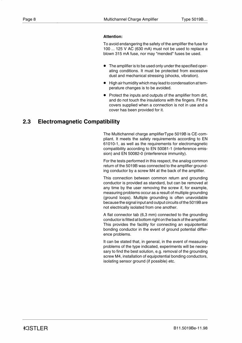
Attention:
To avoid endangering the safety of the amplifier the fuse for100 ... 125 V AC (630 mA) must not be used to replace ablown 315 mA fuse, nor may "mended" fuses be used.
w The amplifier is to be used only under the specified oper-ating conditions. It must be protected from excessivedust and mechanical stressing (shocks, vibration).
w High air humidity which may lead to condensation at tem-perature changes is to be avoided.
w Protect the inputs and outputs of the amplifier from dirt,and do not touch the insulations with the fingers. Fit thecovers supplied when a connection is not in use and acover has been provided for it.
2.3 Electromagnetic Compatibility
The Multichannel charge amplifierType 5019B is CE-com-pliant. It meets the safety requirements according to EN61010-1, as well as the requirements for electromagneticcompatibility according to EN 50081-1 (interference emis-sion) and EN 50082-0 (interference immunity).
For the tests performed in this respect, the analog commonreturn of the 5019B was connected to the amplifier ground-ing conductor by a screw M4 at the back of the amplifier.
This connection between common return and groundingconductor is provided as standard, but can be removed atany time by the user removing the screw if, for example,measuring problems occur as a result of multiple grounding(ground loops). Multiple grounding is often unavoidablebecause the signal input and output circuits of the 5019B arenot electrically isolated from one another.
A flat connector tab (6,3 mm) connected to the groundingconductor is fitted at bottom right on the back of the amplifier.This provides the facility for connecting an equipotentialbonding conductor in the event of ground potential differ-ence problems.
It can be stated that, in general, in the event of measuringproblems of the type indicated, experiments will be neces-sary to find the best solution, e.g. removal of the groundingscrew M4, installation of equipotential bonding conductors,isolating sensor ground (if possible) etc.
Multichannel Charge Amplifier Type 5019B…
B11.5019Be-11.98kISTLER
Page 8

2.4 Tips for using these instructions
These instructions describe the multichannel charge ampli-fier Type 5019B. A supplementary designation defines thevariant and the number of measuring channels.
We recommend reading the entire operating instructionsthrough. Nevertheless if you are in a hurry and already ac-quainted with kISTLER charge amplifiers, you may confineyour reading to the information needed at the moment.
We have endeavoured to set out these instructions as clear-ly as possible, to facilitate your access straight to the infor-mation you want.
Please keep these operating instructions in a safe place,where they are available at all times.
If you lose the instructions, request replacement at oncefrom your kISTLER customer service point.
All data and instructions given here may be altered at anytime without prior notice in the light of technical progress.
Designations in pointed brackets (like <Menu> key) refer tocontrols and displays bearing these names on the amplifieror in the display. The associated parameters are shown insquare brackets [ ].
Instrument modifications (conversions, retrofits etc.) neces-sitate changes in the operating instructions as a rule. In suchcases consult your kISTLER customer service about thepossibilities of updating your documentation.
2 Inportant guidelines
B11.5019Be-11.98 kISTLER
Page 9

3 General description of the amplifier
3.1 Different variants
The complete type designation of the multichannel chargeamplifier consists of the basic code 5019B followed by fourfurther digits: 5019Bvwx. This supplementary designationdefines the housing variant (v), the number of charge ampli-fier measuring channels provided (w), and the options:
v = 0 The instrument is provided for mounting into a 19-inch rack system according to DIN 41 494,width 63 TE and height 4 HE, with side fixingflanges.
v = 1 The instrument is available with a "Schroff CARDPAC" table housing having the same frontplate dimensions as above, with setting-up / car-rying handle.
w = 3 or 4 This indicates the number of independent chargeamplifiers built-in. If the instrument is supplied fit-ted with less than four charge amplifiers, it is al-ways possible to add charge amplifiers later.More is said about this procedure in the remarksbelow concerning options.
x = 0 Instrument without A/D converter board
x = 1 Instrument with A/D converter board forsignal display, Type 5261
3.2 Options
3.2.1 Charge amplifier on Euro-Card Type 5059, additional
With this option, charge amplifier channels may be addedany time if the maximum of four is not being utilized yet. Ex-tension is effected from left to right, taking the next channelnumber in succession. The front plate is already preparedfor this extension: the channels not originally in use are cov-ered on the front plate with a self-adhesive label divided intoseveral sections. By tearing off the appropriate sections thefront plate inscription is exposed successively, according tothe extension stage.
Switching-on the instrument after fitting additional chargeamplifiers calls for reinitializing. This is done following the instruction in the LCD by pressing the <Operate> key, or viathe parallel interface.
Multichannel Charge Amplifier Type 5019B…
B11.5019Be-11.98kISTLER
Page 10

3.2.2 A/D converter board for signal display Type 5261
Subsequent with equipment of the A/D converter board forsignal display.
Procedure: Lift off front plate with manual control. To this purpose, loos-en the four fixing screws and pull the front plate out of its plug-in connection. Insert ADC board into the left hand freeslot. Make sure that the board is inserted with the terminal inforward direction and the components side to the right. Plugthe board with slight pressure into the terminal. Then replacefront plate with manual control and screw it down.
Fig. 2: Installing the option
w Re-insert manual control unit cautiously and screw down
w Connect instrument to mains
w The multichannel charge amplifier is operative again
The pin allocation of the output signals is listed in the section"Technical data / Voltage outputs".
Operation:
w Pin allocation and thus channel assignment is deter-mined by the used dynamometer resp. summing amplifi-er type and the measuring task.
3 General description of the amplifier
B11.5019Be-11.98 kISTLER
Page 11
A/D converter board for signaldisplay Type 5261 (Option)
09 10 97

4 Technical data, Functional description
4.1 IntroductionThe Type 5019B instrument is a multichannel calibratedmultirange charge amplifier with microprocessor control.Typical applications for such multichannel charge amplifiersare to be found in combined force and moment measuringusing piezoelectric multicomponent dynamometers. Thedesired parameters can be adjusted or read off convenientlyby means of a keypad in conjunction with an alphanumericLCD and various LEDs.
All functions can also be adjusted and queried via theIEEE-488 or RS-232C interfaces.
The instrument can be supplied in an all-metal table housingor as a 19-inch plug-in unit conforming to DIN 41 494 Part 5.
4.2 Function of the multichannel charge amplifier Type 5019B
4.2.1 Block diagram
Fig. 3
Multichannel Charge Amplifier Type 5019B…
B11.5019Be-11.98kISTLER
Page 12

The middle part of the block diagram shows the similarcharge amplifiers Type 5059 numbered 1 to 4, executed asplug-in units. Depending on the application, partial fitting-out with less than 8 amplifiers is possible.
The 4 charge inputs (In Channels 1 ... 4) are duplicated, to 4individual BNC sockets and collectively to a high-gradehighly insulating Fischer socket.
The 4 charge amplifier outputs (Out 1 ... 4) are likewise con-nected to BNC sockets, and at the same time paralleled to a15-pin D-Sub female multipoint connector.
To prepare a measurement the various charge amplifier pa-rameters must be set. This is done serially via a data linelooped from one charge amplifier to the next, with the controlunit acting as sender. The data may be put in directly andmanually (keypad) or through one of the interfaces (RS-232C or IEEE-488).In the reverse direction any error mes-sages are transmitted from the charge amplifiers to the con-trol unit likewise as serial data.
The alphanumeric LCD allows for convenient interactive da-ta input via the keypad. Various LEDs on the controller andalso on the different charge amplifiers (channels 1 ... 4) giveinformation on the operating state and any filter functionsswitched in, moreover they signal possible error states. Theparameters adjusted may differ without restriction on thevarious charge amplifier channels.
In the block diagram the power supply is the last unit shown.Here switched controllers are used to minimize the powerloss of the installation.
With regard to the block diagram it should be noted that it hasbeen simplified considerably. For example the charge am-plifiers or the control unit consist of a whole number of func-tion blocks. A comprehensive block diagram of a charge am-plifier unit is described in subsection 4.3.1.
4 Functional description
B11.5019Be-11.98 kISTLER
Page 13

4.2.2 Digital input "Remote Operate"
Switching the charge amplifier over from the waiting state toreadiness for measuring, i.e. from "Reset" to "Operate", canbe performed in various ways:
w manually by pressing the <Operate> key on the front;
w with the appropriate command via the serial interface(RS-232C) or the parallel interface (IEEE-488).
w by leading a signal onto the 25-pin D-Sub socket on therear, inscribed "Remote Operate". Each channel is con-trolled separately (see Technical data / Connections).
w Either a simple mechanical switch or a logic circuit canserve as signal transmitter.
Multichannel Charge Amplifier Type 5019B…
B11.5019Be-11.98kISTLER
Page 14
Bild 4
Bild 5

4.2.3 Power supply
The power supply provides the various function units of theType 5019B with +5 V and ±15 V DC voltages. The mainsoutput on the left in the block diagram leads into a combinedelement comprising a connecting plug, power switch, mainsfilter, fuse holder and voltage selector. The mains filterserves to exclude high frequency interference superposedon the mains from the microprocessor part of the 5019B.
The mains transformer employed is a low-leak, low-loss tor-oidal core type. Since relatively high starting currents mayoccur with toroidal transformers, it is important when chang-ing the fuse to fit exactly the type specified (subsection 2.2).
To minimize the power loss and with it the internal heating ofthe instrument, switched controllers are used for the threevoltage controllers (+5 V, +15 V, -15 V).
Fig. 6: Block diagram for power supply
4 Functional description
B11.5019Be-11.98 kISTLER
Page 15

4.3 Functional principle of the charge amplifier unit
4.3.1 Block diagramThe charge amplifier unit consists of the following functionblocks:
w input stage with selection of measuring range and timeconstant
w amplifier stage with digital voltage divided DAC (Digital-to-Analog Converter) for adjusting the gain
w automatic zero compensation circuit
w low-pass filter, switchable
w signal output
w buffer storage for parameter adjustment and error pro-cessing, also series/parallel conversion
w various LEDs for status display
Fig. 7: Block diagram of charge amplifier unit
Multichannel Charge Amplifier Type 5019B…
B11.5019Be-11.98kISTLER
Page 16

4.3.2 Input stage with range selection
The measuring range is selected by switching-in an appro-priate range capacitor.
The input stage consists of a high-gain operational amplifier(OP1) with MOSFET input stage. It has negative feedbackwith one of the 5 highly insulating range capacitors Cg, thusacting as integrator for input currents flowing in via the[Charge Input]. These currents are generated by chargechanges, i.e. load changes on the piezoelectric sensor.
At the amplifier output a voltage appears proportional to theintegral of the charge change delivered by the sensor. Thedesignation "charge amplifier" is therefore actually incorrectfor this unit; it is rather a charge-to-voltage converter.
In the great majority of cases the following approximate for-mula is sufficient for determining U1:
Q = charge at inputCg = range capacitor
To obtain positive signal voltages for positive mechanicalloads, kISTLER sensors deliver negative charge for posi-tive mechanical loading. Owing to the inverting function ofthe charge amplifier a positive output signal is then assuredunder positive load (e.g. pressure).
The function of the charge-to-voltage conversion may alsobe described as follows:
The amplifier switched as integrator compensates the elec-trical charge from the sensor with an equal charge though ofreverse sign, by building up a voltage U1 via the range ca-pacitor Cg.
An exact calculation, assuming a finite open-loop gain onOP1 and allowing for the input capacitance Ce (= cable ca-pacitance and sensor capacitance), gives for U1:
v = frequency-dependent open-loop gain of OP1,approx. 150'000 for DC
Ce = total input capacitance
4 Functional description
B11.5019Be-11.98 kISTLER
Page 17
U1 = QCg
U1 = QCg
w 1
1 + 1v + Cev w Cg
The right-hand term, the disturbance term, denotes the devi-ation from strict proportionality between input charge Q andoutput voltage U1. In the great majority of cases, however,the simplified formula (1.1) is sufficient.
The particular range capacitor Cg may be paralleled withone of the two time constant resistors Rg (109 Ω and 1011 Ωrespectively). This causes a slow discharge of Cg, which isbeneficial for dynamic measurements.
A normally closed reed relay contact enabling the range ca-pacitor to be bridged serves to reset the amplifier to its resetstatus. The output voltage is then zero, apart from possiblezero deviations.
A [Zero] potentiometer serves to adjust the zero of the inputstage. With it the offset voltage at the [Charge Input] can beadjusted to a minimum.
More detailed explanations concerning the piezoelectricmeasuring principle and charge amplifier theory may befound in the kISTLER reprint 20.116e: "PiezoelectricMeasuring Instruments".
4.3.3 Digital voltage divider (12-bit DAC)
As described under 4.3.2 the range is selected in fixed stag-es by switching capacitors. A continuous fine adjustment iseffected by the programmable digital voltage divider (DAC)connected. The scale and sensor sensitivity values adjust-ed via the keypad are processed by computer and the gainselected accordingly (v = 1 ...10).
4.3.4 Zero compensationBetween DAC and filter stage the amplifier zero offset ismeasured, processed in the zero compensation controlledstage, and fed back into the amplifier input stage. Adjust-ment follows automatically in the [Reset] position.
The zero adjustment of the input stage necessary afterchanging the input transistor (MOSFET) is performed fromthe front after removing the front plate, on the [Zero] poten-tiometer, again in the [Reset] position. The procedure is de-scribed more detailed in subsection 8.2.
Multichannel Charge Amplifier Type 5019B…
B11.5019Be-11.98kISTLER
Page 18

4.3.5 Low-pass filterAfter the DAC stage comes a low-pass filter switchable in 8stages, with Butterworth characteristic. With the filter adjust-ment the upper limit frequency of the measuring system canbe matched to the particular application. For employing ad-ditional external filters on the input or output side, datasheets 12.5321 and 12.5323 should be consulted.
4.3.6 Microprocessor control and monitoring
The charge amplifier units are controlled and monitored col-lectively by an 8-bit microprocessor.
Communication between the charge amplifier part and theprocessor part is serial via appropriate converters, with iso-lation by opto-couplers. Through this link the information ofthe limit detector, [Remote Control] connection and keypadis transmitted to the microprocessor. In the reverse directionthe charge amplifiers are adjusted: ranges, time constant,DAC, filter, [Operate/Reset].
Directly linked with the microprocessor are the LCD display,memories and interfaces.
For storing the program a 64K EPROM is available. The ad-justed parameters are filed in a nonvolatile 2K NOVRAM.These data are stored up to 10 years. The (plug-in) elementmust then be replaced.
4.4 Display, controls and connections
The controller on the front contains in its upper part the illu-minable LCD for up to 4 x 20 characters. In the bottom part isa keypad for controlling the instrument "manually".
4 Functional description
B11.5019Be-11.98 kISTLER
Page 19

4.4.1 DisplayManual control of the instrument is interactive. To facilitateworking the principal parameters and functions appear inthe main menu. The flashing cursor shows which menu itemis active at the moment or where an input is expected:
Fig. 8
[Channels 1 ... 4]:
It is indicated for which of the charge amplifier channels pro-vided the values in the display apply or can be adjusted asthe case may be.
[TSx.xxE+x]:
TS = Sensor sensitivity in pC per mechanical unit (pC/M.U.).The value is displayed in three significant digits and the pow-er of ten.
[SCx.xxE+x]:
SC = scale in mechanical units per volt output signal(M.U. / V ). This value is likewise displayed in three signifi-cant figures and the power of ten.
[LP] = low pass filter:
This shows whether the inbuilt filter has been eitherswitched off or set to one of the 8 limit frequencies available.
Multichannel Charge Amplifier Type 5019B…
B11.5019Be-11.98kISTLER
Page 20

[TC] = time constantThree different statuses can be indicated:
TC = LONG: highest lower limit frequency possible, for in-vestigating slow processes. This setting is used most.
TC = MEDIUM: instead of the word MEDIUM the displayshows the value of the time constant in seconds, since thisdepends on the measuring range.
TC = SHORT: here again the time constant is displayed inseconds. MEDIUM and SHORT are selected for dynamicmeasurements such as vibration, or when special drift prob-lems occur.
[Operate Enable/Disable]:
With this the Reset-Operate function may be activated or de-activated independently for each measuring channel. Thestatus displayed applies to the measuring channel indicatedin the top of the display.
[Monitor On/Off]:
If the instrument is fitted with an A/D converter board for thesignal display, the measured value is shown in mechanicalunits (M.U.) depending on the scale factor.
4.4.2 Controls
Fig. 9: Display and controls
4 Functional description
B11.5019Be-11.98 kISTLER
Page 21
Mechanical Units [M.U.] = Scale [SC] t Uout

The keys have the following functions:
Key 1: <Operate/Reset>
With this key the charge amplifiers are switched from thewaiting state <Reset> to measuring readiness <Operate>and back again. The function of the key depends on the <En-able> or <Disable> status of the charge amplifier channel inquestion, which is shown in the LCD.
The <Operate> status is confirmed by the green LED of thecharge amplifier.
Key 2: <Remote/Local>
This key activates the remote control for switching <Oper-ate/Reset> from outside. The LED beside <Remote> con-firms the switchover to remote control. Under certain condi-tions this LED lights during operation also, via one of the in-terfaces.
Key 3: <Illum>
By pressing this key the background lighting of the LCD canbe switched on. It is switched off again automatically afterabout 30 seconds. However the illumination is activatedagain if any other key is pressed. In addition the display con-trast can be adjusted optimally with the help of a smallscrewdriver on the trimmer potentiometer <LCD Contrast>.
If key 3 is pressed a second time, the lighting is switched offat once.
Key 4: <Menu>
This key switches another menu on the display, e.g. from themain menu into the "RS-232C interface" menu.
Key 5: <Set all Channels>
A submenu is called. All channels can then be adjusted tothe same values as the parameters marked with the cursor.
Keys 6 and 7: <Select>
The parameter or function to be adjusted is selected withthese keys.
Key 8: <Edit>
With key 8 the place to be edited within a parameter is select-ed (the place indicated by the flashing rectangle or cursor).
Multichannel Charge Amplifier Type 5019B…
B11.5019Be-11.98kISTLER
Page 22
Keys 9 and 10: <Edit>
After selecting the right place within a parameter or displayvalue, the desired value is put in with these keys. With key9 a the value is increased, with key 10 s it is lowered.
If the cursor is on a function to be adjusted, e.g. <LP> or<TC>, by pressing key 9 or 10 the available possibilities aredisplayed successively.
Slide switch 11: <Cursor/Lock>
By shifting the slide switch to the left (<Lock> position), oper-ation of the keys (8, 9, 10) needed to change a parameter isblocked. Unintentional altering of the parameter values isprevented by this.
4 Functional description
B11.5019Be-11.98 kISTLER
Page 23

4.4.3 Connections, view of rear plate
Fig. 10: Connections, view of rear plate
Supply voltage selector
Supply connection with fuse holder
IEEE bus connection(Amphenol connector)
RS-232C connection(25-pin D-Sub connector)
Remote control of Reset-Operate function(25-pin D-Sub connector)
Outputs of the 4 measuring channels and their combinations (15-pin D-Sub connector)
Outputs of the 4 measuring channels on BNC sockets, paralleling D-Sub connector
Inputs of the 4 measuring channels led collectively to special Fischer socket
Inputs of the 4 measuring channels, on BNC sockets, connected in parallel with special Fischer socket. (Place protective caps over all channels not in use)
Multichannel Charge Amplifier Type 5019B…
B11.5019Be-11.98kISTLER
Page 24
09 70 12

5 Assembly, installation and first commissioning
5.1 General informationThe multichannel charge amplifier Type 5019B is designedin accordance with degree of protection IP-20 (according toDIN 40050), i.e. for use in enclosed, dry rooms. Excessivedust is to be avoided as is condensing moisture also. Be-cause the proper functioning of a charge amplifier demandsextremely high insulation values in some parts of the instru-ment, the prevailing air humidity must not be allowed tocause condensation in the event of a temperature drop at theinstallation site. If this should happen nonetheless, it is ad-visable to operate the instrument a few hours in the <Reset>mode so that it reaches its normal internal temperature rise.
If there is a possibility of persistent condensing moisture, theinstrument is best left switched on at <Reset> as long as thisdanger is present.
The admisible ambient temperature range of -10°C to 60°Cstipulated in the technical data must be observed. Perma-nent damage must be expected if 70°C or thereabouts is exceeded.
The siting of the instrument must be chosen so that it is notexposed to serious vibration or repeated shocks. Whether avibrational acceleration is to be considered "serious" for theinstrument cannot be defined numerically; the frequency orfrequency range is very important here. Experience teachesthat a vibrational acceleration of no more than 0.5 g isenough to cause damage if the frequency coincides with theresonant frequency of a part inside the instrument.
5.2 Connecting
Mains power connection:
This is effected via the three-wire power cable from a socketwith grounding conductor connection. If it is necessary touse an extension cable, the protection must not be nullifiedby the absence of the grounding conductor connection. Thishas already been mentioned in subsection 2.1.
Above the mains combination element are two sockets, yel-low/green (protective ground) and yellow (system ground orsignal LOW). Normally both sockets are shorted by a jump-er, joining the system ground to the protective ground.
5 Assembly, installation and first commissioning
B11.5019Be-11.98 kISTLER
Page 25

Depending on local conditions, siting of the sensor and dis-tance between sensor and instrument or the quality of thegrounding of the machine on which the sensor is mounted,measuring problems may arise manifesting themselves invarious ways, typically as mains frequency superposed onthe useful signal or pulselike interference due to switchingoperations. Where such problems appear, the shortingjumper mentioned above may be opened to see if this helps.
If the improvement obtained is such that the jumper must beleft opened in operation, make sure that the sensor mountedis connected to the protective ground according to regula-tions (e.g. via the machine to which it is screwed secure).
If the connection of the sensor housing with the protectiveground is not assured, then a connection must be providedto the yellow/green socket on the 5019B. This line must haveat least the same cross section as the conductors of the pow-er cable. A potential equalization line of 1,5 to 2,5 mm2 is ad-visable.
The voltage occurring between the two equipment socketsmust under no circumstances exceed 50 Vrms!
IEEE-488 or RS-232C/TTY connection:
Connection of one of these interfaces is optional and not ab-solutely essential to the function of the instrument.
A commercial cable is used, subject to the following restric-tions:
IEEE-488:
The distance between two instruments must not exceed 2 mand the overall length of the bus must not exceed 20 m.
RS-232C/TTY:
The distance between two instruments must not exceed20 m, equivalent to a cable capacitance of 2500 pF. On theside of the Type 5019B a 25-pin D-Sub connector is used.The wiring of the cable depends on the handshake systemadopted.
Analog signal outputs:
The signals may be taken either at the 15-pin D-Sub connec-tor or at the 4 individual BNC sockets; both outputs are paral-leled permanently. Depending on the cable type or capaci-tance, long connecting cables may lower the attainableupper limit frequency, but no serious errors are to be expect-ed with lengths of 20 to 50 m or so.
Multichannel Charge Amplifier Type 5019B…
B11.5019Be-11.98kISTLER
Page 26

"Transducer" signal inputs:
Here again there are two connection systems paralleled per-manently: A 9-pin teflon-insulated Fischer socket and 4 indi-vidual BNC sockets.
Owing to the extremely high input resistance, these connec-tions are very susceptible to interferences due to static. Theparallel input not in use must therefore be shielded duringoperation. For the same reason the input sockets must beprotected against any form of dirt.
When connecting sensors, even to the BNC sockets, werecommend the use of cables from the kISTLER rangesuch as the Type 1631. These are tested especially for insu-lation resistance and triboelectricity.
When plugging-in the input cable the Type 5019B must beswitched off, so that the reset reed contact is closed anddamage to the input MOSFET is precluded. For the samereason the cables should be shorted with a short piece ofwire before plugging-in, to discharge them.
When working with relatively high sensitivity, i.e. with smallrange capacitor, the following must be noted in addition:
The interference (noise) increases in proportion to the cablelength or cable capacitance. This is specified more exactly inthe technical data.
The input cables should not hang free over lengths longerthan 30 to 50 cm if accelerations or vibrations must be ex-pected during operation. Coaxial cables may generate spu-rious charges if moved, affecting the measurement.
Remote control Operate/Reset:
This is connected only if the switchover from waiting (Reset)to measuring readiness (Operate) is to be effected neither"manually" nor via one of the interfaces. The cables used areuncritical; they need not be either shielded or highly insulat-ing.
As control element a mechanical switching contact or a logicmay serve.
To enhance the immunity to interference the remote operat-ing inputs may be operated with higher voltage. Above 5 V DC operating voltage the noise levels and hysteresis in-crease in proportion to the operating voltage. Depending onthe function desired (active Low or active High), connectionis made according to Fig. 4 or Fig. 5.
5 Assembly, installation and first commissioning
B11.5019Be-11.98 kISTLER
Page 27

Active Low:Set switch of appropriate channel to "Low". When control-ling with logic, connect logic output to channel input (CH)and GND (0V DC) connection.
Note: Active low means that the active state (measuring readi-ness, i.e. operation) is reached when the logic output is at"Low".
Active High: Set switch of appropriate channel to "High". Negative pole ofvoltage source to GND connection. When controlling withlogic, logic output at channel input (CH) and logic ground toGND.
5.3 First commissioningWhen putting the instrument into operation the first time itwould be advisable to connect a simple charge source suchas a hand calibrator Z 13 734 or some other calibrator if oneis available, instead of a sensor. At the signal output any DCmultimeter able to indicate voltages in the ±10 V range is suf-ficient. Both instruments are connected first to channel 1.
This display may appear after switching the power on. Itmeans that an initialization procedure must be started, forexample by pressing the <Operate> key.
The display following confirms the start of internal test pro-grams for verifying the internal RAM and ROM.
Successful completion of the tests is now confirmed and atthe same time the software version number is displayed.
If the instrument was already initialized when the powerswitch was turned on, as will be the case in normal opera-tion, then after a brief display "RS/OP for Coldstart" you getinto this main menu.
By pressing the <Menu> key you get into the charge amplifi-er parameter menu.
Multichannel Charge Amplifier Type 5019B…
B11.5019Be-11.98kISTLER
Page 28
Checksum ErrorRS/OP for Coldstart
or send'CK' for Coldstart
MAIN MENUSet Parameter
RS232C-Interface offIEEE-Interface on
Hello
Test o.k.RAM Test EPROM Test
Kistler Instr. AG
RAM Test EPROM Test
Channel 1TS9.99E+1 SC1.00E+1LP off TC longOP Enb Monitor off

The arrangement of the controls mentioned in the followingtext is shown in Fig. 9. The corresponding item number isbracketed ( ). If the LCD shows the values as in the above ex-ample, this means:
<Channel 1>: Measuring channel 1 is active and the Reset-Operate control is enabled: <Operate Enable>. If anothermeasuring channel is to be enabled for display and editing,switchover is effected with keys <Select> (6) and (7) and<Edit> (9) and (10).
<TS9.99E+1> and <SC1.00E+1>:
With these the default values of the sensor sensitivity(pC/M.U.) and the scale factor (M.U./V) are displayed. It isbest to do an example yourself, starting from the availablecharge source.
If the charge source is a charge calibrator for example, onwhich you can adjust the charge directly in pC (hand calibra-tor Z 13 734), then the M.U. cancels out when you multiplyTS and SC, giving the sensitivity of the relevant measuringchannel in pC/V.
In the following example the instrument is operated manual-ly, i.e. not through one of the interfaces.
Example: If a value of 10 pC/M.U. (TS1.00E+1) is put in for TS and val-ue of 10 M.U./V (SC1.00E+1) for SC, the multiplication thenyields 100 pC/V, i.e. 1 V output voltage for 100 pC inputcharge. The full output voltage range of ±10 V thus corre-sponds to a charge measuring range of ±1000 pC.
Be sure to bring the charge amplifier into the "Operate" state(key 1) immediately before switching-on the chargesource. The status is confirmed by the green LED of themeasuring channel in question. If the <Operate> key is inef-fective, the selected measuring channel has been switchedto <Operate Disable> or else <Operate Remote> is active.
To edit the values <TS> and <SC>, use the keys <Menu> (4)and then <Edit> (9), (10) and (8). With <Select> (6) and (7)you move within the menu from one parameter to the next,with key (8) within a parameter from one place to the next.
<LP OFF> This stands for "Low Pass = Off", i.e. the selecta-ble low-passfilter is (still) switched off. If the word <OFF> isselected with keys <Select> (6) and (7), with the keys <Edit>(9) and (10) the low-pass filter can then be switched on and aparticular limit frequency adjusted. In the above examplewith the (static) charge source the low-pass filter has no ef-fect of course.
5 Assembly, installation and first commissioning
B11.5019Be-11.98 kISTLER
Page 29

<TC LONG> With the measuring channel switched on, thelongest possible time constant is effective, i.e., it is preparedfor quasistatic measurements. As explained above, heretoo a certain value may be adjusted with the <Select> and<Edit> keys. It is defined in seconds and not as lower limitfrequency in Hz, since we are in a very low frequency rangehere. Apart from the <LONG> adjustment two other valuesmay be selected as well, though the application is confinedto the domain of dynamic measurements (e.g. vibration).
If with the values of the above example and TC = 100 sec. thetest with a static charge source is repeated, the slow drop ofthe output voltage starting from 10 V is easily observable. Ifthe charge source is now switched off, still in the operatestatus, the output voltage then jumps first to minus beforedropping back to zero again. The status of a time constantswitched on is indicated on the corresponding charge ampli-fier by a red LED. In the above example the term <Medium>corresponds to 100 sec. and <Short> to 1 sec.
It is reiterated that the adjustments for TS, SC, LP, TC andthe <Operate Enable/Disable> status may be selected dif-ferently at will for each charge amplifier channel. If you famil-iarize yourself with the adjustment possibilities of the Type5019B by "playing" with it, as in the example given above, in-teractive manual operation should present no problems.
5.4 General operation
The basic procedure for adjusting the various parametershas been explained with the example in subsection 5.3. Forgeneral operation in practice there are a few further remarksto be observed:
After switching off the instrument or a power failure, the vari-ous adjustments remain stored in a battery-buffered module(NOVRAM). The battery integrated in this has a life of about10 years.
Multichannel Charge Amplifier Type 5019B…
B11.5019Be-11.98kISTLER
Page 30

When the instrument undergoes an initialization procedure,as after adding another measuring channel or changing theNOVRAM, the adjustments last put in are lost and the defaultvalues are activated again. These values are approximatemeans of the allowed adjustment ranges. When the instru-ment is switched off and on again after error messages[Range>] or [Range<], automatic reset of the TS and SC pa-rameters to the default values ensues. The allowed adjust-ment ranges are:
*) Note: The time constant for medium and short may be read off di-rectly in seconds from the LCD. Its value depends on the pa-rameters TS and SC. The adjustment ranges specifiedabove for TS and SC cannot always be fully exploited, sinceboth together determine the measuring range. If the productTS t SC lies outside certain limits, an error is signalled in theLCD and the red error LED of the measuring channel con-cerned flashes till the adjustment is corrected. The admissi-ble adjustment range for TS and SC is graphed in Fig. 11.
The parameter adjusting keys can be locked with the <Cur-sor Lock> slide switch on the front in the <Lock> position.The functions of the other keys remain unaffected.
With the filter setting <LP> the upper limit frequency of theselected measuring channel is matched to the particularapplication. The following (–3 dB) limit frequencies may beselected:
If LP = OFF is set, the "natural" limit frequency of the meas-uring channel is effective. Depending on the range capacitorswitched-in and the effective ground capacitance, up to180 kHz is reached. It is possible in principle to work with ex-ternal plug-in filters additionally, both on the input and outputsides. For this the data sheets 12.5321 and 12.5323 may beconsulted.
5 Assembly, installation and first commissioning
B11.5019Be-11.98 kISTLER
Page 31
TS = (1.00E-2 ... 9.99E+3) pC/M.U. Default = 9.99E+1
SC = (1.000E-3 ... 9.99E+6) M.U./V Default = 1.00E+1
LP (Tiefpassfilter) 10 Hz ... 30 kHz Default = OFF
TC (Zeitkonstante) Long, Medium, Short Default = LONG *)
10 Hz / 30 Hz / 100 Hz / 300 Hz 1 kHz / 3 kHz / 10 kHz / 30 kHz

Fig. 11: Adjustment ranges for TS and SC
Multichannel Charge Amplifier Type 5019B…
B11.5019Be-11.98kISTLER
Page 32
(1.00E+7)9.99E+6
1.00E+6
1.00E+5
1.00E+4
1.00E+3
1.00E+2
1.00E+1
1.00E+0
1.00E–1
1.00E–2
1.00E–3
1.00
E–2
1.00
E–1
1.00
E+
0
1.00
E+
1
1.00
E+
2
1.00
E+
3
9.99
E+
3(1
.00E
+4)
Transducer Sensitivity <TS> (pC / M.U.)
Sca
le <
SC
> (
M.U
./ V
)
Range <<TS> • <SC> = < 1.00E+0 (1 pC/V)
Range ><TS> • <SC> = > 9.99E+4 (99'900 pC/V)
Min./Max. Adjustment rangeScale <SC> = 1.00E–3 ... 9.99E+6Sensor sensitivity <TS> = 1.00E–2 ... 9.99E+3
Default Value <TS9.99E+1> <SC1.00E+1>

5.5 Operating philosophy
Fig. 12
5 Assembly, installation and first commissioning
B11.5019Be-11.98 kISTLER
Page 33
Main –
Menu
Set
Parameter
RS232–Interface
Off
IEEE–Interface On
Channel
1TS9.99E+1
SC1.OOE+1
LP
Off
T
C O
ffOP Enb
Monitor
Off
RS–232C
Interface
BR 2400 Parity Off
StopBit
1
Odd
DataBit
8
TTY
Off
IEEE488
Interface
Adress O1
Talker
On
Listener Off
Set Par
amet
erRS232–Interface
IEEE–Interface
Select
a s
Select
a s
Select
a s
Select
a s
TS9.99E+1
SC1.00E+1
LP Off
TC Off
OP Enb
Moni
tor Off
BR 24
00St
opBi
t 1
Data
Bit 8
Pari
ty Of
fOdd
TTY Of
f
Adre
sse 1
List
ener
On
Talk
er On
Menu
y
Menu
y
Menu
y

5.6 Typical application
Fig. 13
Multichannel Charge Amplifier Type 5019B…
B11.5019Be-11.98kISTLER
Page 34

5.7 How to work with piezoelectric measuring instruments
When working with piezoelectric measuring instruments itmust be borne in mind that they differ from other instrumen-tation in that they process electrical charges. Such equip-ment is especially suited for dynamic and quasistatic meas-urements, but other criteria apply than those governing cur-rent or voltage measurements for example. Static measure-ments over long time are basically impossible.
When unpacking the sensors and special cables, makesure that their connectors remain clean and dry so that theirhigh insulation resistance is retained.
The teflon insulator of all socket connections in the inputcircuit must be kept absolutely clean and must not betouched with the fingers. If the insulation is no longer as-sured, only extremely clean cleansing agents may be used,such as Type 1003 cleaning spray from kISTLER,Arklone 113 or rectified benzene, together with a papercloth that does not shed fibres.
For connecting the sensors to the charge amplifier onlylow-noise special cables conforming to data sheet 15.011may be used. Ordinary commercial coaxial cables wouldgenerate triboelectricity and falsify the measured result.
When several sensors are paralleled the charge amplifiermeasures the sum of all charges.
Application example:A typical example is the paralleling of four force measuringelements and measuring the total force.
The polarity of the sensor signal is normally negative (pres-sure increase generates negative charge). In the chargeamplifier the negative charge is converted into a positivevoltage.
Cables must be short-circuited before connecting them tothe charge amplifier, otherwise there is a danger of destroy-ing the input MOSFET. The charging may be due to a highlyloaded sensor for instance. To discharge, use a short pieceof wire or a screwdriver, shorting the middle pin of the plugwith the plug housing.
When working on the installation (connecting sensors andcables) the chargeamplifier must be at [Reset]. It is advisa-ble to adjust the largest scale. The same precautions are ad-visable after longer out-of-operation times.
5 Assembly, installation and first commissioning
B11.5019Be-11.98 kISTLER
Page 35

The time constant of the charge amplifier must normally beset to [Short] or [Medium] for measuring dynamic processesor during pauses, in order to avoid drift. Switchover to [Long]is needed only for quasistatic measurements or calibration.
Ground loops may cause interference. This may be reme-died by mounting the sensor insulated from the measuringobject, or using insulating couplings in conjunction with sep-arate ground lines (insulating couplings Type 1737, 1739).
Overdriving by excessively strong charge signals will notharm the amplifier in principle, though with more than tenfoldoverdrive the charge may generate an inadmissibly highvoltage. The voltage level depends on the charge, the totalinput capacitance (sensor and cable capacitance) and therange capacitor.
Example:A load washer Type 9041 (–4,2 pC/N) loaded with 60 kN de-livers a charge around 250'000 pC. Total capacitance, withshort connecting cable and in the most sensitive range of thecharge amplifier, is typically 250 pF. In this example the volt-age reaches 1000 V and would destroy the input MOSFET.
To avoid brief saturation due to charge peaks (caused typi-cally by impact or structure-borne noise with accelerationsensors) we advise using an input (RC) filter such as Type5321A...
5.8 Error signalsError signals are put out on the two bottom lines of the LCD orby the red LED arranged at the top for each measuring chan-nel. The error display is intermittent.
5.8.1 Error signals while starting
"Checksum Error RS/OP for Coldstart or send CK forColdstart"This message appears for example when a charge amplifierboard is fitted or removed. It is cleared by pressing <Oper-ate>.
"SRAM - Error remove Nonvolatile SRAM":The battery-buffered storage module or its battery is defec-tive and the unit must be replaced.
"EPROM Error remove EPROM":A defect on the EPROM memory module containing the op-eration software.
Multichannel Charge Amplifier Type 5019B…
B11.5019Be-11.98kISTLER
Page 36

5.8.2 Error signals during operation
"Out of Range>>": The admissible measuring range is too small. The error sig-nal disappears as soon as the values of [TS] and [SC] givean admissible range.
"<<Out of Range": The selected measuring range is too small; the error signaldisappears as soon as the [TS] and [SC] values yield an ad-missible range.
"Overload":The signal at the charge amplifier output has exceeded themaximum admissible value of ±10 V. This message and theflashing of the LED belonging to the charge amplifier appeareven if the overloading was only brief, i.e. the affected meas-uring channel functions normally again as soon as the signallies inside the admissible range once more, but the error sig-nal remains till it is cleared by <Reset>.
"Out of Zero":This signals excessive zero offset of the charge amplifier inthe <Reset> state. The cause may be a defective MOSFETfor example, or a wrongly adjusted trimmer potentiometer,or else a fault on the automatic zero correction (see 8.2: Re-placing the input MOSFET).
"Range Change during Operate":This means an attempt has been made to alter one of the pa-rameters [TS] or [SC] during the <Operate> state. Remedy: <Reset> and then correct the adjustment.
"Syntax Error"This appears after an incorrect command input.
"I/O Buffer Overflow"The input string is too long or an output has been requestedwhich cannot be made ready completely in the output buffer.
"RS 232C Overrun Error"Transmission error via the serial interface.
"Frame or Parity Error"Transmission error of the serial interface.
5 Assembly, installation and first commissioning
B11.5019Be-11.98 kISTLER
Page 37

5.9 TroubleshootingThe troubleshooting tips below are confined to localizing thedefective part, and are not intended for carrying out repairs.
When troubles occur on the measuring installation the faultcan be localized by proceeding methodically. With the spe-cifically piezoelectric elements of the measuring chain pro-ceed as follows:
w Connect the signal output in question with an oscillo-scope (DC mode)
w Switch the charge amplifier to [Short] and for a brief mo-ment to [Reset].Observe the reaction of the charge amplifier output volt-age:
No output signal despite dynamic loading of the sensor:
w Make sure that the mains voltage is present and all instru-ments are switched on.
w Check the [TS] and [SC] adjustments. They may be tooinsensitive.
w Inspect all input cables. A plug may have come loose.
w Apply a known charge at the signal input (with charge cal-ibrator 5357A or hand calibrator Z 13'734 for example). Ifthere is still no output signal, the charge amplifier is de-fective. In an emergency a battery in series with a highlyinsulating capacitor will suffice as charge source.
w If an output signal appears, however, it must be assumedthat one of the cables or sensors is defective, or discon-nected. By systematically replacing the individual partsthe one at fault is revealed.
Output signal approx. ± 12 ... ± 15 V (positive or negativesaturation):
w Disconnect the input cable and switch to [Reset]. If theoutput voltage is still unchanged, the charge amplifierchannel in question is defective.
w If the output voltage now returns to zero, this means ashort-cicuit on one of the input cables or sensors. Un-couple one by one, afterwards switching briefly to [Reset]each time, till the defective part is found.
Multichannel Charge Amplifier Type 5019B…
B11.5019Be-11.98kISTLER
Page 38

Drift (zero change at <Operate>):
w If the drift with the most sensitive (lowest) adjustment ofthe amplifier (equivalent to [TS] t[ SC] = 1 pC/V) is muchmore than 30 mV/s (= 0,03 pC/s), an attempt must bemade to find the reason. It is usually poor insulation or adefective MOSFET.
6 Operating via parallel interface IEEE-488
6.1 IntroductionThe parallel interface conforms to the standards IEEE-488-1978 and IEC 625-1, which are functionally identical.
To operate the interface, computer support is required in ac-cordance with the standard.
6.2 Technical dataStandard IEEE-488-1978
Distance between 2 instruments 2 m maximum
Maximum length of bus 20 m
Maximum number of instruments 15 on the bus
Address range 0 ... 30
Function listener, talker
Input buffer 95 bytes
Output buffer 255 bytes
Interface functions SH1, AH1, L3, LE0, T5,TE0, SR1, RL1, PP0, DT1,C0, E1
Multiline commands LLO, GTL, UNL, UNT, SPE, SPD
Uniline commands IFC, REN, EOI, SRQ, ATN
6 Operating via parallel interface IEEE-488
B11.5019Be-11.98 kISTLER
Page 39

6.3 FunctionThe purpose of the standard interface is to decode the in-structions sent by the computer via the standard bus cableand transmit them on to the processor system of the Type5019B . In the case of the IEEE-488 computer interface a dif-ferent address is allocated to each instrument connected,with address numbers 0 ... 30 allowed. In many computerconfigurations, however, not all addresses are still freely se-lectable.
An amplifier adjusted as receiver (listener) may receive datafrom the control computer. Data transmission is in ASCII for-mat (American Standard Code of Information Interchange).For data exchange from the Type 5019B to the computer theinstrument must be adjusted as sender (talker).
The Type 5019B can be switched for both functions simulta-neously (talker and listener).
In the present case all amplifier parameters can be remote-controlled via the interface. Not implemented is the trans-mission of measured data, because this would necessitatean additional A/D converter and appropriate software for theparticular application.
6.4 Controls and connections
The arrangement of the connections is shown in Fig.10.
6.5 Operation
6.5.1 Instruction line (input buffer)
For each line several adjustment and query commands (in-structions without parameter field) may be strung in any se-quence. An instruction line must be concluded with a validterminator.
Terminator:
<CR> <LF> with / without EOI
<CR> with / without EOI
<LF> with / without EOI
only EOI
Multichannel Charge Amplifier Type 5019B…
B11.5019Be-11.98kISTLER
Page 40

Command structure:
header field --> parameter field --> separator
header field 2 characters
parameter field 1...7 characters
allowed separators , ; : /
blanks are ignored when putting-in
large or small letters allowed
separator may be omitted at last instruction in the line
instruction without parameter field:query parameter adjusted momentarily
Processing an instruction line:
w After recognizing the terminator, the instruction line isworked off one command after another, carrying outevery instruction at once except the adjustment com-mands TS and SC.
w The adjustment commands TS and/or SC are executedonly after processing the instruction line.
w In the display the menu is shown according to the lastcommand executed.
Buffer overflow:
Further characters are checked only for terminators. Errorbit "Overflow" is set and service request (SRQ) triggered ifnecessary.
Syntax error:
Further command processing is interrupted. Error bit "Syn-tax" is set and service request (SRQ) triggered if necessary.
Query commands:
The momentarily adjusted parameter, together with theheader field and separator, are taken from the input bufferinto the output buffer ready for querying.
6 Operating via parallel interface IEEE-488
B11.5019Be-11.98 kISTLER
Page 41

6.5.2 Dealing with errors
For each kind of error a bit is assigned in the error byte andserial poll register. The SRQ condition byte is built up simi-larly.
Values:
Bit 20 syntax error in input line
Bit 21 overflow on in- or output buffer
Bit 22 end of input line reached
Bit 23 parameter checksum error
Bit 24 charge amplifier error
Bit 25 RAM R/W error
Bit 26 (reserved for SRQ)
Bit 27 EPROM error
w Once an error occurs it stays in the error byte and serialpoll register till it is rectified (charge amplifier error,EPROM error, RAM R/W error, parameter checksum er-ror) or rendered invalid by a new instruction line (syntax,overflow, charge amplifier error, end of input line).
w After concluding the processing of the instruction line theerror byte is updated (syntax, overflow, end of input linereached), filed in the serial poll register and service re-quest (SRQ) triggered if necessary.
End of input line:
This bit is set if the instruction line has been worked off with-out syntax errors.
Local (manual operation):
Error byte and serial poll register are likewise updated (ad-justing errors, overload, zero), service request (SRQ) trig-gered if necessary.
The following adjusting errors may occur:
[TS Sensor Sensitivity] outside the valid range
[SC Scale] outside the valid range
[TS t SC] adjustment range outside the valid range
Unallowed parameter change in [Operate] setting
The charge amplifier error byte is coded in detail in subsec-tion 6.5.4 Instruction set.
w The SRQ conditions are set by the CS instruction.
w The error byte may be queried with the command CE(transfer in decimal form with two ASCII digits) or with se-rial poll (transfer in binary form).
Multichannel Charge Amplifier Type 5019B…
B11.5019Be-11.98kISTLER
Page 42

6.5.3 Query line (output buffer)
At every query command the momentarily adjusted param-eter together with the separator from the input buffer is madeready in the output buffer for querying.
Structure
Header field-->parameter field-->separator
Header field 2 characters (capital letters)
Parameter field 1 to 7 characters
Separator taken from input line
Terminator:The query line is concluded with the terminator agreed in ac-cordance with command CT. The last byte is always sentwith EOI.
Empty output buffer:Only the terminator agreed according to the CT command issent as reply. The last byte is always sent with EOI.
Buffer overflow:Queries which would make the output buffer overflow arenot filed. Further queries are ignored and the "Overflow" er-ror bit is set.
Apart from monitoring, queries serve also for "learning" avalid adjustment.
6.5.4 Instruction setParameter commands:
LVn Charge amplifier (LV) selection
n=0 set all LV with same parametersn=1 --> LV 1n=2 --> LV 2n=3 --> LV 3n=4 --> LV 4
6 Operating via parallel interface IEEE-488
B11.5019Be-11.98 kISTLER
Page 43

Important:
Charge amplifiers must be selected before every parame-ter command. If parameters are arrayed in a string, the se-lection must be made only once at the beginning of thestring. If a control command is inserted in the string, thecharge amplifier selection must be repeated.
OEn Operate Enable/Disable
n=0 --> Disablen=1 --> Enable
TSn.nnE±e Sensor sensitivityAdjustment range: 1.00E-2 ... 9.99E+3
Example: TS2.45E+0 for 2,45 pC/M.U.
SCn.nnE±e ScaleAdjustment range: 1.00E-3 ... 9.99E+6
Example: SC 5.00E-2 for 0,05 M.U./Volt
Any input format is admissible for TS and SC, for exampleTS2.45 or TS.245E+01.
TCn Time constant
n=0 --> switchover to [Long]n=1 --> switchover to [Short]n=2 --> switchover to [Medium]
LPn Low-pass filter
n=0 --> filter switched off [OFF]n=1 --> 10 Hzn=2 --> 30 Hzn=3 --> 100 Hzn=4 --> 300 Hzn=5 --> 1 kHzn=6 --> 3 kHzn=7 --> 10 kHzn=8 --> 30 kHz
ROn Reset / Operate
n=0 --> Resetn=1 --> Operate
Multichannel Charge Amplifier Type 5019B…
B11.5019Be-11.98kISTLER
Page 44

Option:
V = Measured value querying from any channel.The chan-nel must be selected with the parameter selection LVn.Only one channel at a time may be queried. The chan-nel selection LV0 for all channels is eliminated. Themeasured value is displayed exponentially,e.g. 3.25E+0.2.
Control commands:
CHn Header for output line
n=0 --> without headern=1 --> with header
CLn Switchover unlocked/locked
n=0 unlockedn=1 locked
(in IEEE mode query command only)
CN Output of number of charge amplifiers mounted
CRn Switchover local/remote(for RS-232C operation only)
n=0 --> localn=1 --> remote
CSnnn SRQ condition --> instrument reports at corresponding error (not available with RS-232C)
nnn = sum of bit values (value to be adjusted)
Bit 20 syntax error in input lineBit 21 overflow on in- or output bufferBit 22 end of input line reachedBit 23 parameter checksum errorBit 24 charge amplifier errorBit 25 RAM R/W errorBit 26 SRQ actuatedBit 27 EPROM error
Example: SRQ for syntax, overflow and charge amplifier errors:
20 + 21 + 24 = 1 + 2 + 16 = 19Command = CS019 (always 3 digits)
6 Operating via parallel interface IEEE-488
B11.5019Be-11.98 kISTLER
Page 45

Bit 7 --> signals whether an SRQ condition has been set ornot:
Bit 7 --> 1 : SRQ condition setBit 7 --> 0 : SRQ condition not set
After a fulfilled SRQ condition the error byte may be queriedby serial poll.
CTn Terminator Type
n=0 --> <CR> <LF> with EOI
n=1 --> <CR> with EOI
n=2 --> <LF> with EOI
Note: EOI is not present in the instruction set of the serial interface RS-232C.
CU Instrument identification via interface
CVn.nn Software revision number query
CXn Remote (external) operate enable
n=0 --> Disablen=1 --> Enable
ORn Clear overload error messagen=0 no actionn=1 clear error message
CO A/D converter board mountedn=0 option not providedn=1 option provided
(query command only !)
Error query:
CEnnn Query instrument-specific error byte
nnn=decimal sum of error byte
Weight 1: syntax error in input lineWeight 2: input or output buffer overflowWeight 4: end of input line reachedWeight 8: parameter checksum errorWeight 16: charge amplifier errorWeight 32: RAM R/W errorWeight 64: RS-232C transmission error
or SRQ actuationWeight 128: EPROM error
Multichannel Charge Amplifier Type 5019B…
B11.5019Be-11.98kISTLER
Page 46

Note:
When "Weight 16 (ch. ampl.) error" occurs, it must be withthe next query "LVn;CCmm" which charge amplifier andwhich error are involved:
LVn;CCmm Query ch. ampl. error byte
n = 0 --> query all ch. ampl. error bytesn = 1 --> LV 1n = 2 --> LV 2n = 3 --> LV 3n = 4 --> LV 4
mm= decimal sum of error byte put out
Weight 1: minimum measuring range understeppedWeight 2: maximum measuring range exceededWeight 4: range change during [Operate]Weight 8: overloadWeight 16: zero error
6 Operating via parallel interface IEEE-488
B11.5019Be-11.98 kISTLER
Page 47

6.5.5 Typical program for computers with IEEE-488 interface
System configuration:Software: Microsoft Quick Basic V4.5Hardware: IBM AT or compatible IBM AT
with Keithley PC < > 488 interface board with driver softwareCEC 488 from version 2.05 for Quick Basic
Instrument address for 5017B/5019B 5Sensor sensitivity –4.3 pC/NMeasuring range 200 NScale 20 M.U./VFilter 300 Hz
The example sets the parameters for the 1st charge amplifier (LV1) and queries the error byte constantly. Ifan error occurs, an error signal is displayed on the screen and the program is stopped.
CALL initialize (31.0) 'Initialize systemCALL send (5, "LV1;RO0", status%) 'ResetCALL send (5, "LV1;TS4.3;SC20", status%) 'Sensor sensitivity '–4.3 pC/N
'Scale 20 M.U./V
CALL send (5, "LV1;LP4", status%) 'Filter 300 HzCALL send (5, "LV1;RO1", status%) 'Operate
r$ = "CE000" 'Initialize variable r$
WHILE r$ = "CE000" OR r$ = "CE004"CALL send (5, "CE", status%) 'Query command for error byte
IF status% < > 0 THEN PRINT status%: STOP 'Provide space for error byter$ = SPACE$(30)
CALL enter (r$, length%, 5, status%) 'Read-in error byteIF status% < > 0 THEN PRINT status%:STOP 'IEEE bus errorr$ = LEFT$ (r$, length%) 'Format data string
WENDCLS 'Clear computer screen
SELECT CASE r$ 'Verify error CASE "CE001"
PRINT "Syntax error in input line" CASE "CE002"
PRINT "In- or output buffer overflow" CASE "CE008"
PRINT "Parameter checksum error" CASE "CE016"
PRINT "Charge Amplilfier error" CASE "CE032"
PRINT "RAM R/W error" CASE "CE064"
PRINT "Reserved for SRQ" CASE "CE128"
PRINT "EPROM error"END SELECTEND
Multichannel Charge Amplifier Type 5019B…
B11.5019Be-11.98kISTLER
Page 48

7 Operating via serial interface RS-232C
7.1 IntroductionThe standardized serial interface makes possible a point-to-point connection between a computer and the Type 5019B.Via this link all parameters can be adjusted and queried. Ameasured value query is possible with the optional A/D con-verter board for signal display, Type 5261.
7.2 Technical dataStandard RS-232C or V24
Distance between 2 instruments 20m max. (max. cable capacitance 2500 pF)
Switch settings (read after power-up):
Baud rates 110, 300, 600, 1200, 2400, 4800, 9600
Data bits 7 or 8Stop bits 1 or 2Parity without, even or odd
Input buffer 95 bytes
Output buffer 255 bytes
Software protocol XON/XOFF admissible
7.3 FunctionThe interface decodes the instructions sent from the com-puter and directs them on to the control system of the Type 5019B. The computer can also make the interfacesend various data requested.
Data transmission takes place in ASCII format. The numberof data bits, stop bits and the transmission speed are adjust-ed with coding switches on the rear of the instrument.
7.4 Controls and connections
The arrangement of the connections is shown in Fig. 10(view of rear plate).
7 Operating via serial interface RC-232C
B11.5019Be-11.98 kISTLER
Page 49

7.5 Operation
7.5.1 Commissioning
Parameter reinitialization and self-test:
[Power] switch on mains power
[Operate] press key[Reset]
The instrument performs a self-test, during which the pa-rameters are initialized anew.
Display:
With <Select> set the cursor to the IEEE interface in themain menu.
With <Edit> change the interface from IEEE-488 toRS-232C.
With <Menu> go to RS-232C interface.
Display:
BR = baud rate
Parity = [Off] = no parity[Even] = even parity[Odd] = odd parity
Stop bit = [1] or [2], number of stop bits
Data bit = [7] or [8], number of data bits
TTY = [Off] or [On], operating mode TTY
Note:Depending on the serial number of the installation, the val-ues displayed may be altered either on the back DIP switch-es or edited interactively with the LCD using the keys on thefront.
After this the <Menu> key is used to return to the main menu.
The interface is initialized automatically after every parame-ter change.
Multichannel Charge Amplifier Type 5019B…
B11.5019Be-11.98kISTLER
Page 50
KISTLER Instrumente AGResult of RAM/ROM testand software version number

7.5.2 Setting the TTY interface
The TTY interface is initialized via the control unit in the RS-232C interface menu. The addresses 0 to 3 are avail-able. The active and passive switchover of the interfacetakes place on the controller board.
Procedure:
Disconnect the instrument from the mains power.
To make the adjustments the front plate must be removedwith the manual control and the controller board behind itdrawn out of its guides. For this purpose the four fixingscrews must be unfastened and the front plate pulled outof its socket connection.
Fig. 14: Controller printer circuit board
Setting the TTY receiver
Fig. 14, below:--> active/passive with switch SW1A
Setting the TTY transmitter
Fig. 14, below:--> active/passive with switch SW1B
After making the adjustments the controller board ispushed into its guides again. A little pressure is neces-sary to reestablish the socket connection. The front plateis then fitted with the manual controls and screwed down.
7 Operating via serial interface RS-232C
B11.5019Be-11.98 kISTLER
Page 51

Reconnect the instrument to the power supply.
Instruction set for current loop (TTY)^A select 5019B with address 0^B select 5019B with address 1^C select 5019B with address 2^D select 5019B with address 3
The instrument address is to be sent immediately beforethe command and without separator.E.g. ^ALV0:TS:SC for outputting the sensor and scale ad-justments of all channels.
Connecting Type 5019B in a current loop (TTY)
Fig. 15: TTY connection
Note:
w Use zero modem circuit
w Send instrument address even if only one instrument isconnected
7.5.3 Instruction line (input buffer)
On each line several adjustment and query instructions(i.e. commands without parameter field) may be arrayed inany sequence. Each instruction line must be concluded witha valid terminator.
Terminator: <CR> <LF> or <CR> or <LF>
Multichannel Charge Amplifier Type 5019B…
B11.5019Be-11.98kISTLER
Page 52

Command structure:
Header field --> parameter field --> separator
Header field 2 charactersParameter field 1 ... 7 charactersSeparators allowed , ; : /
Blank characters are ignored when put inCapital or small letters allowedSeparator may be omitted at the last command
Command without parameter field: query of the momentar-ily adjusted parameter
Processing an instruction line:
w After recognition of the terminator the instruction line is-worked off one command after another, each commandbeing executed at once, except the adjustment com-mands TS and SC.
w The adjustment commands TS and SC are executed on-ly after the instruction line has been processed.
w The display shows the menu according to the last com-mand executed.
Buffer overflow:Further characters are verified only for terminators.The"overflow" error bit is set.
Syntax error:The processing of further commands is discontinued.The"syntax" error bit is set. Transmission errors lead to a syntaxerror additionally.
Query commands:The momentarily adjusted parameter is taken from the inputbuffer into the output buffer ready for querying, together withthe header field and the separator.
7.5.4 Dealing with errorsFor every kind of error a bit is assigned in the error byte.
Weight:
Bit 20 syntax error in input lineBit 21 in- or output buffer overflowBit 22 end of input line reachedBit 23 parameter checksum errorBit 24 charge amplifier errorBit 25 RAM R/W errorBit 26 RS-232C transmission errorBit 27 EPROM error
7 Operating via serial interface RS-232C
B11.5019Be-11.98 kISTLER
Page 53

w Once an error occurs it remains in the error byte and serialpoll register till the error ist corrected (charge amplifier er-ror, EPROM error, RAM R/W error, parameter checksumerror) or rendered invalid by a new command line (syn-tax, overflow, charge amplifier error, RS-232C transmis-sion error, end of input line).
w After concluding the processing of the command line, theerror byte is updated (syntax, overflow, transmission er-ror, adjustment error).
The following adjustment errors may occur:
w [TS sensor sensitivity] outside its valid range.
w [SC Scale] outside its valid range.
w [TS t SC] adjustment range outside its admissible limits
w Unallowed parameter change in [Operate] setting
The charge amplifier error byte is explained in detail in sub-section 6.5.4: Instruction Set.
w End of input line:This bit is set if the instruction line has been worked offwithout syntax errors.
w Local (manual) operation:The error byte is likewise updated (adjustment error,overload, zero).
w The error byte may be queried with the command CE(transmission in decimal form with two ASCII digits).
Multichannel Charge Amplifier Type 5019B…
B11.5019Be-11.98kISTLER
Page 54

7.5.5 Query line (output buffer)
At every query command the momentarily adjusted param-eter is taken from the input buffer into the output buffer readyfor querying, together with the header field and separator.
Command structure:
Header field --> parameter field --> separator
Header field 2 characters (capitals)
Parameter fielf 1 ... 7 characters
Separator taken from input lines
Note: For CH0 the header field is omitted
w Terminator:The query line is concluded with the terminator agreedaccording to the command CT.
w Empty output buffer:Only the terminator agreed according to the commandCT is sent as answer.
w Buffer overflow:Queries which would cause an output buffer overflow arenot filed. Further queries are ignored and the overflow er-ror bit is set.
w Besides monitoring purposes, queries serve also for"learning" a valid adjustment.
7.5.6 Instruction setThis is summarized in subsection 6.5.4: Parallel interface,Instruction set, which applies also to the serial interface. Mi-nor differences in the interface commands are pointed out inthis subsection.
7. Operating via serial interface RS-232C
B11.5019Be-11.98 kISTLER
Page 55

8 Maintenance
8.1 Safety rulesIf it is to be assumed that safe operation is no longer possi-ble, the instrument must be taken out of operation and se-cured against inadvertent starting. Refer to subsection 2.1.
8.2 Replacing the input MOSFET
w If LCD [Out of Zero] and [Error] lamp flashes.
w If drift > 30 mV/s with adjustment [TS] t [SC] = 1 pC/V;
Procedure:
w Disconnect instrument from mains power.
w Remove left-hand part of front plate after unfastening thefixing screws.
w Carefully pull out the charge amplifier board whose errorlamp is lit, drawing it only by the two aluminium fixing an-gles at the top and bottom of the board.
w After unfastening the three fixing screws the two shield-ing plates can be removed. The MOSFET input transistor(kISTLER article No. 5.811.019) plugged into its teflon-insulated mounting can now be changed using tweezersor suitable pliers.
Note:MOSFET components are destroyed by static charges.Consequently the person handling them must be grounded,preferably with a commercial grounding armband. Alsoavoid seizing the MOSFET by one of its connecting wiresfirst; always touch its housing first.
w After changing, fit the shielding plates. Carefully push theamplifier unit into the basic instrument.
w If the new MOSFET input stage is to operate with thesmallest possible drift, a zero adjustment must be madein the [Reset] state. Prior to this the installation shouldhave been operating about 60 minutes. The adjustmentis effected with the bottom trimmer potentiometer imme-diately above the (bottom) fixing angle. A commercialmultimeter with a range of typically 200 mV and ≥ 1 MΩinput resistance will suffice as zero indicator. The multi-meter is connected to the [Charge Input].
Multichannel Charge Amplifier Type 5019B…
B11.5019Be-11.98kISTLER
Page 56

8.3 Calibrating the charge amplifier
The processor-controlled charge calibrator Type 5357Ashould be used preferably for calibrating. The procedure isexplained in the operating instructions for that instrument.
If no special charge calibrator is available, as a stopgap a DCreference voltage source may be used in conjunction with acalibrating capacitor.
Example:If a charge signal is to be generated, as a piezoelectric pres-sure sensor with a sensitivity of say –78.2 pC/bar would yieldfor a pressure rise of 50 bar, the necessary calibrationcharge is calculated first:
Q = –78.2 pC/bar t 50 bar = –3910 pC.
Since the calibration voltage may not exceed ±30 V and cal-ibrating capacitors are available only in decadic grading, acalibration voltage of –3.91 V and a capacitor of 1000 pF(Type 5371A1000) are selected.
Q = U t C = -3.91 V t 1000 pF = –3910 pC.
The charge amplifier inverts the signal polarity (invertingamplifier); consequently a negative charge is needed toyield a positive output voltage.
Connection:The calibrating capacitor is connected, either in place of asensor or paralleling this, to one of the [Sensor] sockets. Theother end of the cable must be terminated with low impe-dance by the voltage source, in the voltage-free state too.
Adjustment:
Menu [TS] 7.82E+1 (-78.2 pC/M.U.)[SC] 5.00E+1 (50 M.U./V)[LP] OFF[TC] [Long]
Switch the instrument to [Operate].Switch on the DC reference voltage source.
A voltage of 1 V DC appears at the [Analog Output].
If 5.00E+0 (5 M.U./V) is adjusted for [SC], the output voltageis 10 V.
8 Maintenance
B11.5019Be-11.98 kISTLER
Page 57

Note:The calibrating capacitor must be plugged directly into theType 5019B and not in the (more remote) voltage source.This makes the connecting cable used uncritical with regardto insulation and triboelectricity. Another advantage is thatthe cable capacitance is not paralleled with the input capaci-tance, which would increase the noise signal unnecessarily.
If the calculated and indicated values differ, this can be cor-rected within certain limits with the second trimmer potentio-meter (from the bottom).
8.4 Drift of the charge amplifier
Any drift ascertainable at the output of a charge amplifier(slow zero shift in the course of time in [Operate] state andwith time constant TC = Long) cannot be avoided within thespecified tolerance of 0,03 pC/s. If this value is largely ex-ceeded however, this can be due to one of the followingcauses:
Cause 1Drift due to insufficient insulation resistance in the feedbackpath of the charge amplifier (e.g. poorly insulating range ca-pacitor). This drift is always in the direction of the zero outputsignal.
Cause 2Drift due to damaged or defective MOSFET input stage (thedirection may be positive or negative).
Cause 3Drift due to insufficient insulation resistance at charge ampli-fier input (the direction may again be either positive or nega-tive, depending on the polarity of the input offset voltage).
Remedy may be obtained by the following measures:
With cause 1
Symptom: Exponential signal decay after applying a staticcharge signal.
w Check whether [Long] time constant has been selected.[Medium] or [Short] produce the same effect as insuffi-cient insulation resistance in the feedback path.
w If the trouble persists, poor insulation resistance on theparticular range capacitor selected must be suspected.The competent distributor must be approached to get theinstrument repaired.
Multichannel Charge Amplifier Type 5019B…
B11.5019Be-11.98kISTLER
Page 58

With cause 2
Symptom: The polarity of the drift does not change with thepolarity of the zero offset at the input.
w Note: A slight drift as specified in the technical data isnormal for the charge amplifier.If it is excessive:
Change the MOSFET, see subsection 8.2.
With cause 3
Symptom: The polarity of the drift depends on the polarity ofthe zero offset at the input.
w The most probable cause is insufficient insulation resis-tance in the input circuit. This can be verified with an insu-lation tester Type 5493.
Procedure:Clean the sensor plug or change the sensor, and clean thesensor cable (cable connections) or change the cable.
If the trouble persists, as a stopgap adjust the zero of the in-put stage as accurately as possible (see subsection 8.2, ze-ro adjustment). Then contact the competent distributor tohave the instrument repaired.
Note:Cause 3 can easily be diagnosed by removing the sensorand sensor cable from the charge amplifier input and con-necting a charge calibrator. Cause 3 may also be due to in-sufficient insulation resistance of the MOSFET.
8 Maintenance
B11.5019Be-11.98 kISTLER
Page 59

9 Technical data
9.1 Charge amplifier Type 5019B
Charge amplifier:
Number of channels 3 or 4
Measuring range for ± 10 V FS (5 decades) pC ± 10 ... 999'000
Sensor-sensitivity [TS] pC/M.U. 0,01 ... 9990(selectable with three significant digits)
Scale [SC] M.U./V 0,001 ... 9'990'000 a)(selectable with three significant digits)
Errors up to ± 99.9 pC % ≤ ± 3
from ± 100 pC % ≤ ± 1
Linearity errors %FS ≤ ± 0,05 b)
Frequency range –3 dB (filter OFF) kHz ≈0 ... 200
Frequency response error (filter OFF)up to 50 kHz % –1 ... +2up to 200 kHz % –30 ... +3
Low-pass filter (Butterworth 2-pole) –3dB 10Hz ... 30kHz(adjustable in 8 stages: 10, 30, 100...30 000 Hz ± 10%)
Time constant resistanceLong (Cg<1 nF) Ω >1014
Medium Ω approx. 1011
Short Ω approx. 109
Time constant (T = Rg t Cg)
Long s >1000 ... 100'000 c)Medium s 1 ... 10'000Short s 0,01 ... 100
a) > M.U. = mechanical unit e.g. bar, N, g
b) > FS = full scale (end value of measuring range)
c) > The "Long" time constant cannot be used to define the behaviour of the charge amplifier with longmeasuring times (quasistatic measurements). The time behaviour of the signal is then influenced predominantly by the drift (input error current).
Multichannel Charge Amplifier Type 5019B…
B11.5019Be-11.98kISTLER
Page 60

Zero transition at Reset -> Operate switchover pC < ± 0,2Drift (25°C) MOSFET-input current pC/s < ± 0,03
Output output voltage V ± 10overload trigger threshold V approx. 10,5maximum output current mA ± 5output impedance Ω 10(output short-circuit-proof)
Interference due to input cable capacitance pCrms/pF < 2 t 10-5
Output interference (input shielded)at 9,99 pC/V mVrms < 0,8
mVpp < 20
at 1 pC/V mVrms < 1,5
mVpp < 20
Zero error at RESET (max. / typ.) mV < 2 / 0,4(automatic zero correction)trigger threshold for zero out of limit mV approx. ± 10
Temperature coefficient of zero at RESET µV/K approx. 10
Input voltage, maximum admissible(pulse duration < 0,3 s) V ± 125
LogicLogic input level
(Remote Operate, electrically insulated )with operating voltage UB = 5 V U
HV > 2,4
UL
V < 0,8
operating voltage range UB V 4,5 ... 33
Note:With an operating voltage of 4,5 ... 5,5 V the level values for UH and UL are TTL-compatible. From 5,5to 33 V operating voltage the levels and the hysteresis increase in proportion to the operating voltageas follows:
UH
V approx. 0,35 t UB
UL
V approx. 0,17 t UB
Protected against overvoltage up to V ± 75with pulse duration ≤ 0,1 s up to V ± 300
Operate delayExternal Operate (active Low) ms approx. 15External Operate (active High) ms approx. 15with IEEE command GET ms approx. 20with IEEE command RO1 ms approx. 120
Reset delayExternal Reset (active Low) ms approx. 15External Reset (active High) ms approx. 15with IEEE command RO0 ms approx. 120
9 Technical data
B11.5019Be-11.98 kISTLER
Page 61

General data:
Temperature range for specifications °C 0 ... 50for function °C –10...60
Voltage supply (switchable) V AC 230/115% +15/–22Hz 48 ... 62
Power consumption VA approx. 20
Dimensions ( Order designation Type 5019B1...)Housing with setting-up / carring handle)DIN 41494 Part 5 width TE 63
height HE 4
width mm 396height mm 187depth mm 280
Weight kg approx. 8
Connections:Mains 2P + E (measuring circuit off ground) Type IEC 320C14
(Degree of protection I)
Remote operate Type D-Subconnector 25-pinaccord. to DIN 41652
Pin assignment
Note: A "Remote/External Operate" for only one channel is not possible.
Maximum voltage between power system ground and signal common Vrms ≤ 50
Measuring inputs, types (both parallel) Fischer 9-pole/BNC neg.
Pin assignment
Channel No. (BNC)Fischer pin No
Multichannel Charge Amplifier Type 5019B…
B11.5019Be-11.98kISTLER
Page 62
Pin 1: 4,5 ... 33 V DC14: 0 VDC 2: CHN 1
1 2 3 4 GND
2+3 4+5 6+9 7+8 1

Voltage outputs, types (both parallel) D-Sub connector 15-pin/BNC neg.Pin assignment
Channel No. (BNC)D-Sub pin No.
9.2 Connection assignment/cable wiring for RS-232C:
5019B PC PC(DB-25S, accord. to DIN 41652) (DB-25P) or (DE-9P) Without hardwired handshake, max. 1200 baud (for TTY applications):
With hardwired handshake, max. 9600 baud:
9 Technical data
B11.5019Be-11.98 kISTLER
Page 63
1 2 3 4 GND
1 2 3 4 9

9.3 Explanations to the technical data
Below some terms from the table of technical data will be ex-plained in more detail where this is deemed necessary forbetter understanding.
Note: All designations inscribed on the actual instrument are givenin square brackets in these operating instructions, e.g.[Scale].
9.3.1 Measuring rangeThis denotes the electrical charge generating a voltage of10 V at the voltage output [Output 10 Ω] according to the me-nu adjustment [Sensor Sensitivity TS] and [Scale SC]. Ac-cording to the sensor sensitivity the measuring range usedin practice can be indicated in mechanical units.
The maximum charge range for 10 V output voltage is:
Range = 10 t SC t TS [pC]
On the LCD it is not the measuring range that is read off oradjusted but the scale [SC] in mechanical units per volt [me-chanical units / V] for a given (adjusted) sensor sensitivity[TS] in pC/mechanical unit [Sensor Sensitivity (pC/mechani-cal unit)].
9.3.2 Sensor sensitivity[TS = Sensor Sensivity (pC/mechanical unit)]
This contains the coefficient of measure for converting frommechanical units into an electrical charge. The values statedare sensor-specific and may be taken from the calibrationsheet supplied with every sensor.
9.3.3 Frequency response error
These values represent the maximum deviation of the am-plitude at the voltage output from the nominal value as it oc-curs in the medium frequency range, but not significantlyabove the lower limit frequency.
Multichannel Charge Amplifier Type 5019B…
B11.5019Be-11.98kISTLER
Page 64

9.3.4 Time constant resistance, time constant
The time constant T with which the output signal from themeasuring chain dies away with stationary measuring sig-nal present is given by the product of the adjusted range ca-pacitor Cg and the adjusted time constant resistance Rgparalleling it.
T = Rg t Cg (see block diagram Fig. 7). The longest time con-stants in the individual ranges exist when in the [Long] set-ting the resistance Rg is given only by the insulation resis-tance of the particular range capacitor. We then speak of so-called quasistatic measurements.
Through the finite insulation resistance of the sensor or itscable a drift current flows (caused for example by an offsetvoltage in the input circuit). Owing to this, in the extremecase the amplifier may drift to the limit after a certain time. Toavoid this, a [Medium] or [Short] time constant may be se-lected, forgoing quasistatic measurements. The dischargeof the particular range capacitor associated with this coun-teracts the charging by drift currents.
The [Medium] and [Short] operating modes are selected fordynamic measurements. For questions concerning zeroand drift correction see 8.2 and 8.4 respectively. The timeconstant T determines the lowest detectable frequency ofthe measuring chain - the lower limit frequency:
9.3.5 Noise signal due to input cable capacitance
Paralleling capacitances at the charge amplifier input, as en-sues after connecting any sensor cable, amplifies the noisesignals always present. The spurious charge generated bythis is superposed on the signal charge delivered from thesensor.
Typical coaxial cables have 70...100 pF capacitance permeter length, then there is the capacitance of the sensor it-self. Information on cables is given in data sheet 15.011.
9.3.6 Output interferenceThe output interference specified with shielded input (noisesignals due to input cable capacitance negligible) is inde-pendent of the Cg (range capacitor) selected.
The total interference at the output is arrived at by adding theoutput interference and the transformed noise signal at theoutput as described in 9.3.5 (depending on the scale).
9 Technical data
B11.5019Be-11.98 kISTLER
Page 65
fg= 12π t Rg t Cg

10 Program disk
With these operating instructions comes a diskette for IBM-compatible PCs with DOS operating system. It contains soft-ware to facilitate operating the multichannel charge amplifi-ers Type 5017B and Type 5019B via the interfaces IEEE-488 or RS-232C as the case may be.
In addition to the runnable program file 5017.EXE also con-tains the associated source programs (development envi-ronment: Quick-Basic Ver. 4.5 Engl.). This enables you toperform any program adaptations yourself.
In the text file also on the diskette (German: LIESMICH andEnglish: README) you will find the necessary instructions
In addition these text files include:
w data on the diskette contents and version number
w data on the hardware required
w data on the connecting cables needed
w a general program description
The easiest way to obtain a printout on a printer connected tothe parallel port is to put in the following on DOS level:
TYPE A:LIESMICH > PRN or TYPE B:README > PRN
Enclosure: Program disk (No 7.642.012) Auxiliary program for programming the interfaces.
Multichannel Charge Amplifier Type 5019B…
B11.5019Be-11.98kISTLER
Page 66

11 WarrantyThe equipment supplied by KISTLER INSTRUMENTE AGWINTERTHUR is covered by a warranty against faulty ma-terial and workmanship.
The warranty extends over one year from the date of deliv-ery.
When submitting warranty claims, the items of equipmentconcerned must be delivered to the manufacturer's works orto the regional distributor free of all charges, stating full de-tails as to the nature of the claims.
Settlement of warranty claims may be effected at the manu-facturer's discretion either by reconditioning or replacing thefaulty items, or by crediting their value. Items of equipmentdamaged as a result of improper use or handling are not cov-ered by the warranty.
Our responsibility under the warranty is strictly restricted tothe above provisions, and we specifically decline any liabilityfor damages incurred consequent upon the use or operationof our equipment.
11 Warranty
B11.5019Be-11.98 kISTLER
Page 67
