operating instructions models 33100 and 33101 hydrostatic ... · operating instructions models...
TRANSCRIPT

1
Operating Instructions Models 33100 and 33101 Hydrostatic Test Pumps
August 2013
DIMENSIONS: 16” (40cm) L x 22” (55cm) W x 18” (45cm) H WEIGHT: 87 lbs., 39.5 kg PUMP: Triplex Plunger: Positive Displacement
Inlet & outlet: ½” NPT Capacity: 1gpm, 7 lpm Pressure: Maximum pressure 1000psi (68bar) Operating Speed: 1725rpm Lubrication: Continuous oil bath, 30W non-detergent Hydraulic Oil – filled to mark on sight glass Shaft Size: 5/8” hollow
MOTOR: 1hp , 115/230V, 1ph, 60hz, 1725rpm CONTROL: Adjustable pressure relief valve GAUGE: Glycerin filled, 0-2000psi (136 bar) DISCHARGE HOSE:
½” x 10’ (3m), 2000psi (136 bar)
33100
DIMENSIONS: 16” (40cm) L x 22” (55cm) W x 18” (45cm) H WEIGHT: 87 lbs., 39.5 kg PUMP: Triplex Plunger: Positive Displacement
Inlet & outlet: ½” NPT Capacity: 1gpm, 7 lpm Pressure: Maximum pressure 1000psi, (68bar) Operating Speed: 1725rpm Lubrication: Continuous oil bath, 30W non-detergent Hydraulic Oil - filled to mark on sight glass Shaft Size: 5/8” hollow
MOTOR: 1hp, 220V, 1ph, 50hz, 1725rpm CONTROL: Adjustable pressure relief valve GAUGE: Glycerin filled, 0-2000psi (136 bar) DISCHARGE HOSE:
½” x 10’ (3m), 2000psi (136 bar)
33101
2
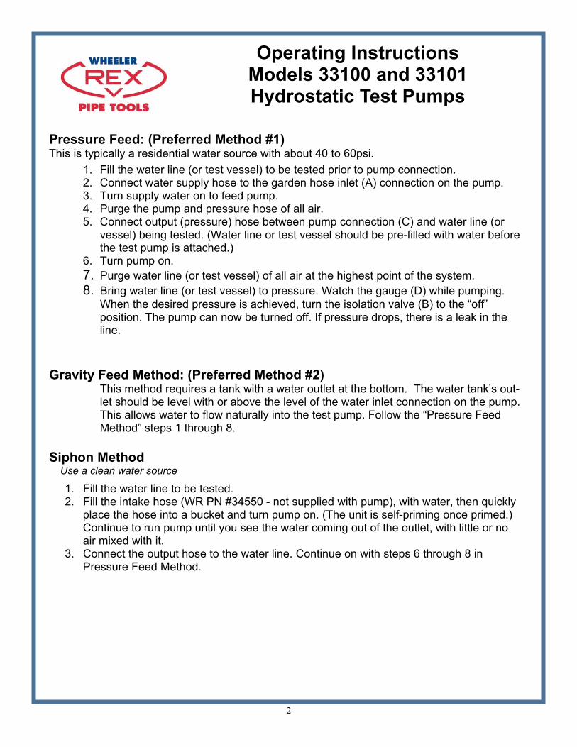
Pressure Feed: (Preferred Method #1) This is typically a residential water source with about 40 to 60psi.
1. Fill the water line (or test vessel) to be tested prior to pump connection. 2. Connect water supply hose to the garden hose inlet (A) connection on the pump. 3. Turn supply water on to feed pump. 4. Purge the pump and pressure hose of all air. 5. Connect output (pressure) hose between pump connection (C) and water line (or
vessel) being tested. (Water line or test vessel should be pre-filled with water before the test pump is attached.)
6. Turn pump on. 7. Purge water line (or test vessel) of all air at the highest point of the system. 8. Bring water line (or test vessel) to pressure. Watch the gauge (D) while pumping.
When the desired pressure is achieved, turn the isolation valve (B) to the “off” position. The pump can now be turned off. If pressure drops, there is a leak in the line.
Gravity Feed Method: (Preferred Method #2)
This method requires a tank with a water outlet at the bottom. The water tank’s out-let should be level with or above the level of the water inlet connection on the pump. This allows water to flow naturally into the test pump. Follow the “Pressure Feed Method” steps 1 through 8.
Siphon Method Use a clean water source
1. Fill the water line to be tested. 2. Fill the intake hose (WR PN #34550 - not supplied with pump), with water, then quickly place the hose into a bucket and turn pump on. (The unit is self-priming once primed.) Continue to run pump until you see the water coming out of the outlet, with little or no air mixed with it. 3. Connect the output hose to the water line. Continue on with steps 6 through 8 in Pressure Feed Method.
Operating Instructions Models 33100 and 33101 Hydrostatic Test Pumps

3
Pre-Setting Your Pump Your pump can be pre-set to a specific pressure easily by adjusting the pressure relief valve.
1. Loosen the jam nut (G), then unscrew (counterclockwise direction) the pressure relief valve knob on pressure relief valve (F) a few turns. (Test pump comes pre-set at 1000psi). Be sure not to unscrew the relief valve all the way. Parts can be easily lost.
2. Add a ball valve (not supplied with pump) to the end of the high pressure hose. 3. Follow steps 2 through 4 from the ‘Pressure Feed Method’. 4. As water is flowing out of the high pressure hose, turn the ball valve to the off
position. 5. Slowly start turning the knob on the pressure relief valve (F) (in the clockwise
direction) by ¼ turn increments, until you reach the desired pressure. Tighten the jam nut (G) when finished.
6. Your test pump is now pre-set. This eliminates over-pressurizing the water line (or the vessel).
Operating Instructions Models 33100 and 33101 Hydrostatic Test Pumps

4
Operating Instructions Models 33100 and 33101 Hydrostatic Test Pumps
A Garden Hose Inlet
B Isolation Valve
C High Pressure Hose Connection
D Gauge
E Pump Valve
F Pressure Relief Valve
G Jam Nut
H Oil Cap / Dipstick
F G H
E D B C
A

5
Troubleshooting Your Pump
Test pressure not being reached: x� Possible air in line (or test vessel).
¡� Air needs to be purged from system. ¡� If using the Siphon Method and not getting pressure, try the
‘Pressure Feed’ or ‘Gravity Feed Method’ to ensure water is getting into the pump.
¡� Check strainer / O-Ring for cracks (A). This is inside garden hose connection
x� Pressure relief valve not adjusted properly. ¡� Turn relief valve counterclockwise and watch for change in
pressure. ¡� Remove pump from system and follow steps 1 thru 6 of the
“Pre-Setting Your Pump” section.
Pump Maintenance
x� Pump 50/50 antifreeze/water solution through pump after each use to lubricate internal parts of pump and to avoid freezing in cold weather.
x� Check strainer O-Ring (A) for cracks prior to each use.. x� Before running the pump, check the oil level using the dip stick (H).
Refer to the recommended lubrication marked on the crank case of the pump.
x� Hypro pump - change oil every 500 hours of operation x� Plunger Seal Kit Wheeler Rex PN 36389. x� Suction Hose Wheeler Rex PN 34550.
Operating Instructions Models 33100 and 33101 Hydrostatic Test Pumps
CAUTION !!! This pump is designed for water only!!
The pump is equipped with an adjustable pressure relief valve (F), which helps protect the system from being
over pressurized. It can be preset by plugging the end of the hose. Turn the adjusting knob clockwise to increase pressure and counterclockwise to decrease.

6
7
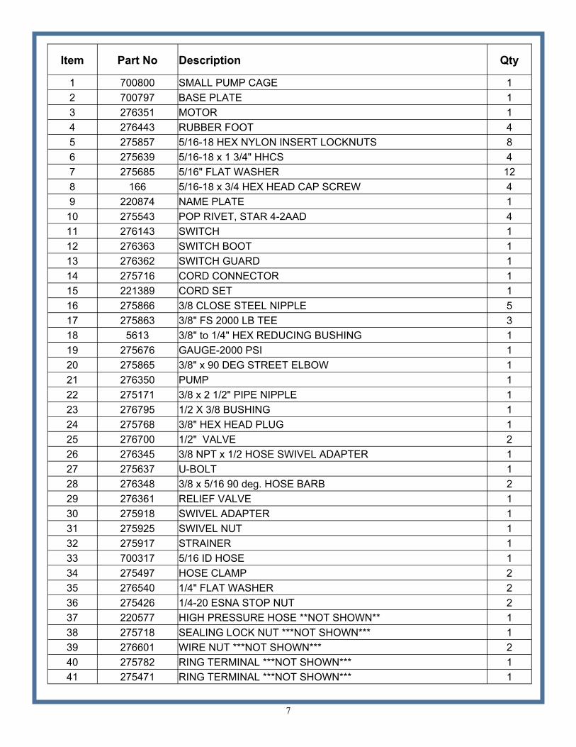
Item Part No Description Qty
1 700800 SMALL PUMP CAGE 1 2 700797 BASE PLATE 1 3 276351 MOTOR 1 4 276443 RUBBER FOOT 4 5 275857 5/16-18 HEX NYLON INSERT LOCKNUTS 8 6 275639 5/16-18 x 1 3/4" HHCS 4 7 275685 5/16" FLAT WASHER 12 8 166 5/16-18 x 3/4 HEX HEAD CAP SCREW 4 9 220874 NAME PLATE 1
10 275543 POP RIVET, STAR 4-2AAD 4 11 276143 SWITCH 1 12 276363 SWITCH BOOT 1 13 276362 SWITCH GUARD 1 14 275716 CORD CONNECTOR 1 15 221389 CORD SET 1 16 275866 3/8 CLOSE STEEL NIPPLE 5 17 275863 3/8" FS 2000 LB TEE 3 18 5613 3/8" to 1/4" HEX REDUCING BUSHING 1 19 275676 GAUGE-2000 PSI 1 20 275865 3/8" x 90 DEG STREET ELBOW 1 21 276350 PUMP 1 22 275171 3/8 x 2 1/2" PIPE NIPPLE 1 23 276795 1/2 X 3/8 BUSHING 1 24 275768 3/8" HEX HEAD PLUG 1 25 276700 1/2" VALVE 2 26 276345 3/8 NPT x 1/2 HOSE SWIVEL ADAPTER 1 27 275637 U-BOLT 1 28 276348 3/8 x 5/16 90 deg. HOSE BARB 2 29 276361 RELIEF VALVE 1 30 275918 SWIVEL ADAPTER 1 31 275925 SWIVEL NUT 1 32 275917 STRAINER 1 33 700317 5/16 ID HOSE 1 34 275497 HOSE CLAMP 2 35 276540 1/4" FLAT WASHER 2 36 275426 1/4-20 ESNA STOP NUT 2 37 220577 HIGH PRESSURE HOSE **NOT SHOWN** 1 38 275718 SEALING LOCK NUT ***NOT SHOWN*** 1 39 276601 WIRE NUT ***NOT SHOWN*** 2 40 275782 RING TERMINAL ***NOT SHOWN*** 1 41 275471 RING TERMINAL ***NOT SHOWN*** 1

8
9
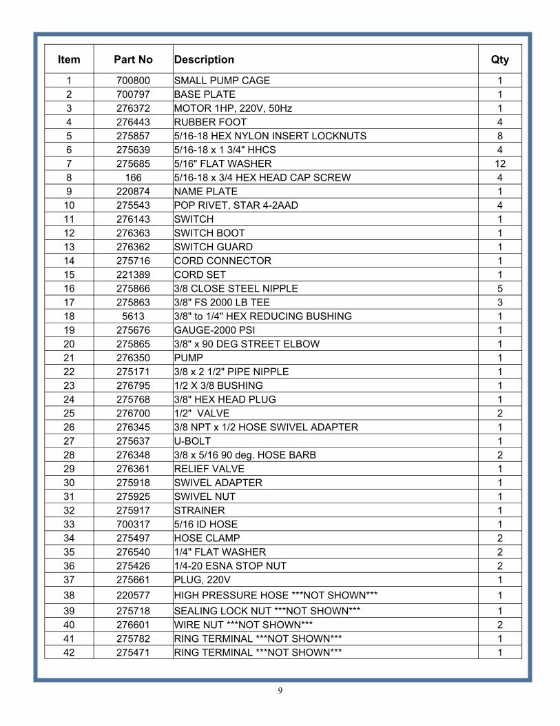
Item Part No Description Qty
1 700800 SMALL PUMP CAGE 1 2 700797 BASE PLATE 1 3 276372 MOTOR 1HP, 220V, 50Hz 1 4 276443 RUBBER FOOT 4 5 275857 5/16-18 HEX NYLON INSERT LOCKNUTS 8 6 275639 5/16-18 x 1 3/4" HHCS 4 7 275685 5/16" FLAT WASHER 12 8 166 5/16-18 x 3/4 HEX HEAD CAP SCREW 4 9 220874 NAME PLATE 1
10 275543 POP RIVET, STAR 4-2AAD 4 11 276143 SWITCH 1 12 276363 SWITCH BOOT 1 13 276362 SWITCH GUARD 1 14 275716 CORD CONNECTOR 1 15 221389 CORD SET 1 16 275866 3/8 CLOSE STEEL NIPPLE 5 17 275863 3/8" FS 2000 LB TEE 3 18 5613 3/8" to 1/4" HEX REDUCING BUSHING 1 19 275676 GAUGE-2000 PSI 1 20 275865 3/8" x 90 DEG STREET ELBOW 1 21 276350 PUMP 1 22 275171 3/8 x 2 1/2" PIPE NIPPLE 1 23 276795 1/2 X 3/8 BUSHING 1 24 275768 3/8" HEX HEAD PLUG 1 25 276700 1/2" VALVE 2 26 276345 3/8 NPT x 1/2 HOSE SWIVEL ADAPTER 1 27 275637 U-BOLT 1 28 276348 3/8 x 5/16 90 deg. HOSE BARB 2 29 276361 RELIEF VALVE 1 30 275918 SWIVEL ADAPTER 1 31 275925 SWIVEL NUT 1 32 275917 STRAINER 1 33 700317 5/16 ID HOSE 1 34 275497 HOSE CLAMP 2 35 276540 1/4" FLAT WASHER 2 36 275426 1/4-20 ESNA STOP NUT 2 37 275661 PLUG, 220V 1 38 220577 HIGH PRESSURE HOSE ***NOT SHOWN*** 1 39 275718 SEALING LOCK NUT ***NOT SHOWN*** 1 40 276601 WIRE NUT ***NOT SHOWN*** 2 41 275782 RING TERMINAL ***NOT SHOWN*** 1 42 275471 RING TERMINAL ***NOT SHOWN*** 1

10

11
Wheeler Rex • 3744 Jefferson Road • Ashtabula, Ohio 44005 Tel: 800-321-7950 or 440-998-2788 • Fax: 440-992-2925
[email protected] • www.wheelerrex.com