operating instructions hydraulic comparison test pump
TRANSCRIPT
Hydraulic comparison test pump, model CPP4000-X EN
Hydraulic comparison test pump, model CPP4000-X
Operating instructions
2 WIKA Operating Instruction, model CPP4000-X
EN Operating instruction, model CPP4000-X Page 2 - 31
Further languages can be found at www.wika.com.
© 2016 WIKA Alexander Wiegand SE & Co. KG
All rights reserved.
WIKA® is a registered trademark in various countries.
Prior to starting any work, read the operating instructions!
Keep for later use!
Contents
WIKA Operating Instruction, CPP4000-X 3
EN
14
15
54
60
.0 0
8/2
01
6 G
B
1. General Information ............................................................................................................. 5
2. Safety .................................................................................................................................. 6
2.1 Explanation of symbols .................................................................................................... 6
2.2 Intended use ...................................................................................................................... 6
2.3 Improper use ...................................................................................................................... 7
2.4 Personnel qualification ..................................................................................................... 7
2.5 Personal protective equipment ........................................................................................ 8
2.6 Special hazards ................................................................................................................. 8
2.6.1 Mineral oils health and safety information ............................................................................. 9
2.6.2 Other liquids ........................................................................................................................ 9
2.7 Labelling, safety marks ................................................................................................... 10
2.7.1 Product label ...................................................................................................................... 10
2.7.2 Symbols............................................................................................................................. 10
3. Design and Function .......................................................................................................... 11
3.1 Description ...................................................................................................................... 11
3.2 Scope of delivery ............................................................................................................. 11
3.3 Base unit .......................................................................................................................... 11
3.3.1 Spindle pump..................................................................................................................... 13
3.3.2 Reservoir ........................................................................................................................... 13
3.3.3 Control valves .................................................................................................................... 13
3.3.4 Connection blocks ............................................................................................................. 13
3.4 Function ........................................................................................................................... 13
4. Transport, packaging and storage ...................................................................................... 15
4.1 Transport ......................................................................................................................... 15
4.2 Packaging and storage ................................................................................................... 15
5. Commissioning, operation ................................................................................................. 16
5.1 Unpacking the hydraulic comparison test pump .......................................................... 16
5.2 Environmental requirement ............................................................................................ 16
5.3 Assembly of base units Fastening base to bench ........................................................ 16
5.4 Assembly ......................................................................................................................... 16
5.4.1 Connection of the test item and the reference measuring instrument .................................. 16
5.4.2 Filling the base unit with liquid ............................................................................................ 17
5.4.3 Post assembly test ............................................................................................................. 17
5.5 Procedure ........................................................................................................................ 18
5.5.1 To apply pressure .............................................................................................................. 18
5.5.2 During calibration ............................................................................................................... 18

Contents
4 WIKA Operating Instruction, model CPP4000-X
EN
14
15
54
60
.00
08
/20
16
GB
5.6 Completion ...................................................................................................................... 18
5.7 Cleaning gauges .............................................................................................................. 19
6. Faults................................................................................................................................. 21
7. Maintenance, cleaning and servicing ................................................................................. 24
7.1 Periodic maintenance ..................................................................................................... 24
7.2 Corrective maintenance .................................................................................................. 24
7.2.1 General .............................................................................................................................. 24
7.2.2 Removing the cover ........................................................................................................... 26
7.2.3 Reservoir seals .................................................................................................................. 26
7.2.4 Valve seals ........................................................................................................................ 26
7.2.5 Spindle pump..................................................................................................................... 26
7.2.6 Hub assembly .................................................................................................................... 27
7.3 Cleaning ........................................................................................................................... 27
7.3.1 Cleaning the unit and checking the liquid levels. ................................................................. 27
8. Dismounting, return and disposal ....................................................................................... 28
8.1 Return ............................................................................................................................... 28
8.2 Disposal ........................................................................................................................... 28
9. Specifications .................................................................................................................... 29
10. Accessories ....................................................................................................................... 31
Declarations of conformity can be found online at www.wika.com.
1. General Information
WIKA Operating Instruction, CPP4000-X 5
EN
14
15
54
60
.0 0
8/2
01
6 G
B
1. General Information
■ The model CPP4000-X hydraulic comparison test pump described in the operating instructions
has been designed and manufactured using state-of-the-art technology. All components are
subject to stringent quality and environmental criteria during production. Our management
systems are certified to ISO 9001 and ISO 14001.
■ These operating instructions contain important information on handling the model CPP4000-X
hydraulic comparison test pump. Working safely requires that all safety instructions and work
instructions are observed.
■ Observe the relevant local accident prevention regulations and general safety regulations for
the range of use of the model CPP4000-X hydraulic comparison test pump.
■ The operating instructions are part of the instrument and must be kept in the immediate vicinity
of the model CPP4000-X hydraulic comparison test pump and readily accessible to skilled
personnel at any time.
■ Skilled personnel must have carefully read and understood the operating instructions, prior to
beginning any work.
■ The general terms and conditions, contained in the sales documentation, shall apply.
■ Subject to technical modifications.
■ Factory calibrations/DKD/DAkks calibrations are carried out in accordance with international
standards.
■ Further information:
WIKA Alexander Wiegand SE & Co. KG
- Internet address: www.wika.de / www.wika.com
- Relevant data dheet: CT 91.01
- Application consultant: Tel.: +49 9372 132-0
Fax: +49 9372 132-406
DH-Budenberg
A division of WIKA Instruments Ltd.
- Internet address: www.wika.de / www.wika.com
- Relevant data sheet: CT 91.09
- Application consultant: Tel.: +44 844 4060086
Fax:+44 844 4060087

2. Safety
6 WIKA Operating Instruction, model CPP4000-X
EN
14
15
54
60
.00
08
/20
16
GB
2. Safety
2.1 Explanation of symbols
WARNING!
... indicates a potentially dangerous situation that can result in serious injury or death,
if not avoided.
CAUTION!
... indicates a potentially dangerous situation that can result in light injuries or
damage to property or the environment, if not avoided.
Information
... points out useful tips, recommendations and information for efficient and
trouble -free operation.
2.2 Intended use
Comparison test pumps serve as pressure generators for the testing, adjustment and calibration of
mechanical and electronic pressure measuring instruments through comparative measurements.
These pressure tests can take place in the laboratory or workshop, or on site at the measuring point.
The hydraulic comparison test pump features two connections, for test item and reference
measuring instrument, which can be used in any order. If one connects the test item and a
sufficiently accurate reference measuring instrument to the test pump, on actuating the pump, the
same pressure will act on both instruments. By comparison of the two measured values at any given
pressure value, a check of the accuracy and/or adjustment of the pressure measuring instrument
under test can be carried out.
The integrated dual-area spindle pump enables rapid filling of the test system and smooth pressure
generation up to 4,000 bar. At the same time, the precise, adjustable spindle pump also enables
fine pressure adjustment.
A control schematic for pressure generation on the instrument base facilitates quick and easy
operation. The pump is further characterized by the spindle which runs solely within the pump body.
This eliminates any harmful bending moment from an externally running spindle and, especially for
field operation, there is the advantage that dimensions of this pump do not alter during operation
through the rotation of the spindle.
2. Safety
WIKA Operating Instruction, CPP4000-X 7
EN
14
15
54
60
.0 0
8/2
01
6 G
B
Information
The term “reference measuring instrument” in these operating instructions refers to
any pressure measuring instrument, such as: pressure gauge, electrical pressure
measuring instrument and pressure transmitter with electrical output. The hydraulic
comparison test pump system is only as accurate as the reference measuring
instrument used. The reference measuring instrument should be regularly calibrated
in order to ensure that its accuracy is maintained.
The instrument has been designed and built solely for the intended use described here, and may
only be used accordingly.
The technical specifications contained in these operating instructions must be observed. Improper
handling or operation of the instrument outside of its technical specifications requires the instrument
to be taken out of service immediately and inspected by an authorised WIKA service engineer.
Handle mechanical precision measuring instruments with the required care (protect from humidity,
impacts, strong magnetic fields, static electricity and extreme temperatures, do not insert any
objects into the instrument or its openings).
If the instrument is transported from a cold into a warm environment, the formation of condensation
may result in instrument malfunction. Before putting it back into operation, wait for the instrument
temperature and the room temperature to equalize.
The manufacturer shall not be liable for claims of any type based on operation contrary to the
intended use.
2.3 Improper use
WARNING!
Injuries through improper use
Improper use of the instrument can lead to hazardous situations and injuries.
▶ Refrain from unauthorised modifications to the instrument.
Any use beyond or different to the intended use is considered as improper use.
2.4 Personnel qualification
WARNING!
Risk of injury should qualification be insufficient
Improper handling can result in considerable injury and damage to equipment.
▶ The activities described in these operating instructions may only be
carried out by skilled personnel who have the qualifications described
below.
▶ Keep unqualified personnel away from hazardous areas.
2. Safety
8 WIKA Operating Instruction, model CPP4000-X
EN
14
15
54
60
.00
08
/20
16
GB
Skilled personnel
Skilled personnel, authorised by the operator, are understood to be personnel who, based on
their technical training, knowledge of measurement and control technology and on their
experience and knowledge of country-specific regulations, current standards and directives,
are capable of carrying out the work described and independently recognising potential
hazards.
Special operating conditions require further appropriate knowledge, e.g. of aggressive media.
DH-Budenberg/WIKA can provide dedicated training courses on the correct use of our
products. Please contact your local office for further details.
2.5 Personal protective equipment
The personal protective equipment is designed to protect the skilled personnel from hazards that
could impair their safety or health during work. When carrying out the various tasks on and with
the instrument, the skilled personnel must wear personal protective equipment.
Follow the instructions displayed in the work area regarding personal protective
equipment!
The requisite personal protective equipment must be provided by the operating company.
Wear safety goggles!
Protect eyes from flying particles and liquid splashes.
2.6 Special hazards
WARNING!
To ensure safe working on the instrument, the operating company must ensure
■ that suitable first-aid equipment is available and aid is provided
whenever required.
■ that the operating personnel are regularly instructed in all topics regarding
work safety, first aid and environmental protection and knows the operating
instructions and, in particular, the safety instructions contained therein.
WARNING!
Residual media on the hydraulic comparison test pump can result in a risk to
persons, the environment and the equipment. Take sufficient precautionary
measures.
2. Safety
WIKA Operating Instruction, CPP4000-X 9
EN
14
15
54
60
.0 0
8/2
01
6 G
B
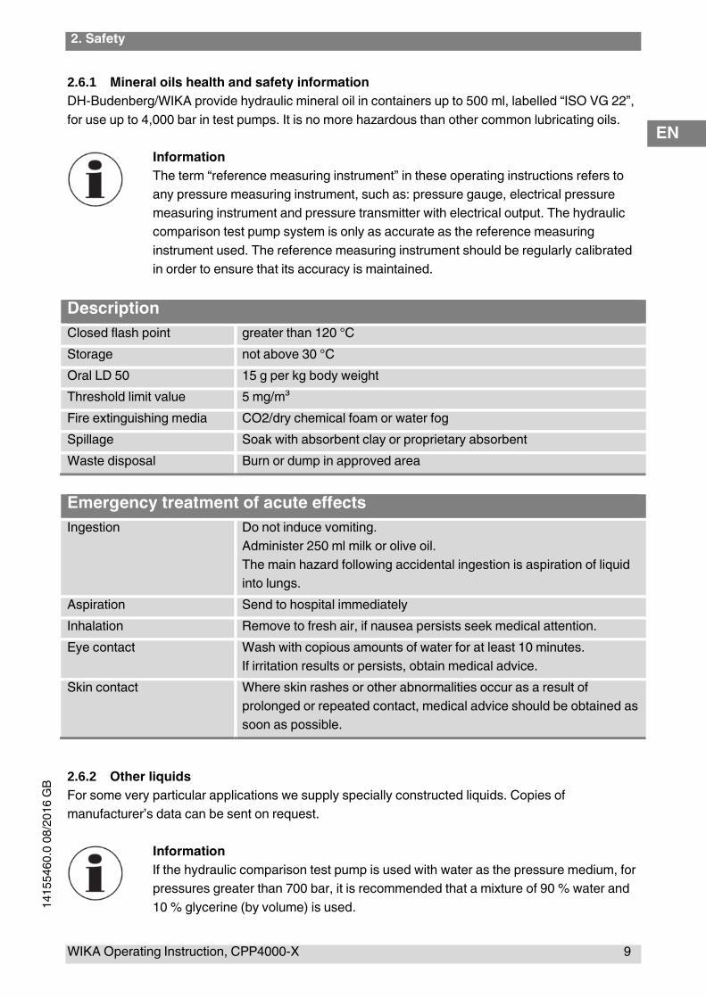
2.6.1 Mineral oils health and safety information
DH-Budenberg/WIKA provide hydraulic mineral oil in containers up to 500 ml, labelled “ISO VG 22”,
for use up to 4,000 bar in test pumps. It is no more hazardous than other common lubricating oils.
Information
The term “reference measuring instrument” in these operating instructions refers to
any pressure measuring instrument, such as: pressure gauge, electrical pressure
measuring instrument and pressure transmitter with electrical output. The hydraulic
comparison test pump system is only as accurate as the reference measuring
instrument used. The reference measuring instrument should be regularly calibrated
in order to ensure that its accuracy is maintained.
Description
Closed flash point greater than 120 °C
Storage not above 30 °C
Oral LD 50 15 g per kg body weight
Threshold limit value 5 mg/m³
Fire extinguishing media CO2/dry chemical foam or water fog
Spillage Soak with absorbent clay or proprietary absorbent
Waste disposal Burn or dump in approved area
Emergency treatment of acute effects
Ingestion Do not induce vomiting.
Administer 250 ml milk or olive oil.
The main hazard following accidental ingestion is aspiration of liquid
into lungs.
Aspiration Send to hospital immediately
Inhalation Remove to fresh air, if nausea persists seek medical attention.
Eye contact Wash with copious amounts of water for at least 10 minutes.
If irritation results or persists, obtain medical advice.
Skin contact Where skin rashes or other abnormalities occur as a result of
prolonged or repeated contact, medical advice should be obtained as
soon as possible.
2.6.2 Other liquids
For some very particular applications we supply specially constructed liquids. Copies of
manufacturer’s data can be sent on request.
Information
If the hydraulic comparison test pump is used with water as the pressure medium, for
pressures greater than 700 bar, it is recommended that a mixture of 90 % water and
10 % glycerine (by volume) is used.
2. Safety
10 WIKA Operating Instruction, model CPP4000-X
EN
14
15
54
60
.00
08
/20
16
GB
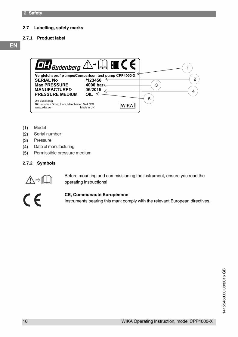
2.7 Labelling, safety marks
2.7.1 Product label
(1) Model
(2) Serial number
(3) Pressure
(4) Date of manufacturing
(5) Permissible pressure medium
2.7.2 Symbols
Before mounting and commissioning the instrument, ensure you read the
operating instructions!
CE, Communauté Européenne
Instruments bearing this mark comply with the relevant European directives.
2
3
4
5
1
3. Design and Function
WIKA Operating Instruction, CPP4000-X 11
EN
14
15
54
60
.0 0
8/2
01
6 G
B
3. Design and Function
3.1 Description
The model CPP4000-X hydraulic comparison test pump features optimal characteristics for use in
the laboratory, as well as the ruggedness needed for industrial applications. It is suitable for
pressure generation up to 4,000 bar.
Test item and reference measuring instrument are connected to the two test connections.
3.2 Scope of delivery
■ Instrument base
■ Dual-area spindle pump for filling, pressure generation and fine pressure adjustment
■ 2 test connections with G ½ female differential nut connection
o Adapter 2 x G1/2 male on M16*1.5(male) with external hardened cone sealing face
■ VG22 mineral oil (0.5 litre)
■ Tool and maintenance set consisting of: 1 hexagon wrench key 3 mm A/F
o 1x 30 mm A/F open-ended spanners
o 2x G1/2 differential nut connections
o 1x G3/8 differential nut connection
o 1x Sealing coned joint
o 2x Sealing coned joint (1 end recessed)
o 1x spirit level
o 4x level plates 1 bag of seals
o 1x pointer punch
o 1x pointer remover
■ Operating instructions in German and English language
Cross-check scope of delivery with delivery note.
3.3 Base unit
The model CPP4000-X base unit consists of a solid aluminum base plate mounted on four
adjustable levelling feet, a spindle pump, reservoir, control valves, pipework to two stainless steel
pressure connection blocks. The pipework and above mentioned assemblies are covered by an
easy to clean ABS cover.
The component identification numbers in brackets in each procedure refer to the following figure.
4. Design and Function
12 WIKA Operating Instruction, model CPP4000-X
EN
14
15
54
60
.00
08
/20
16
GB
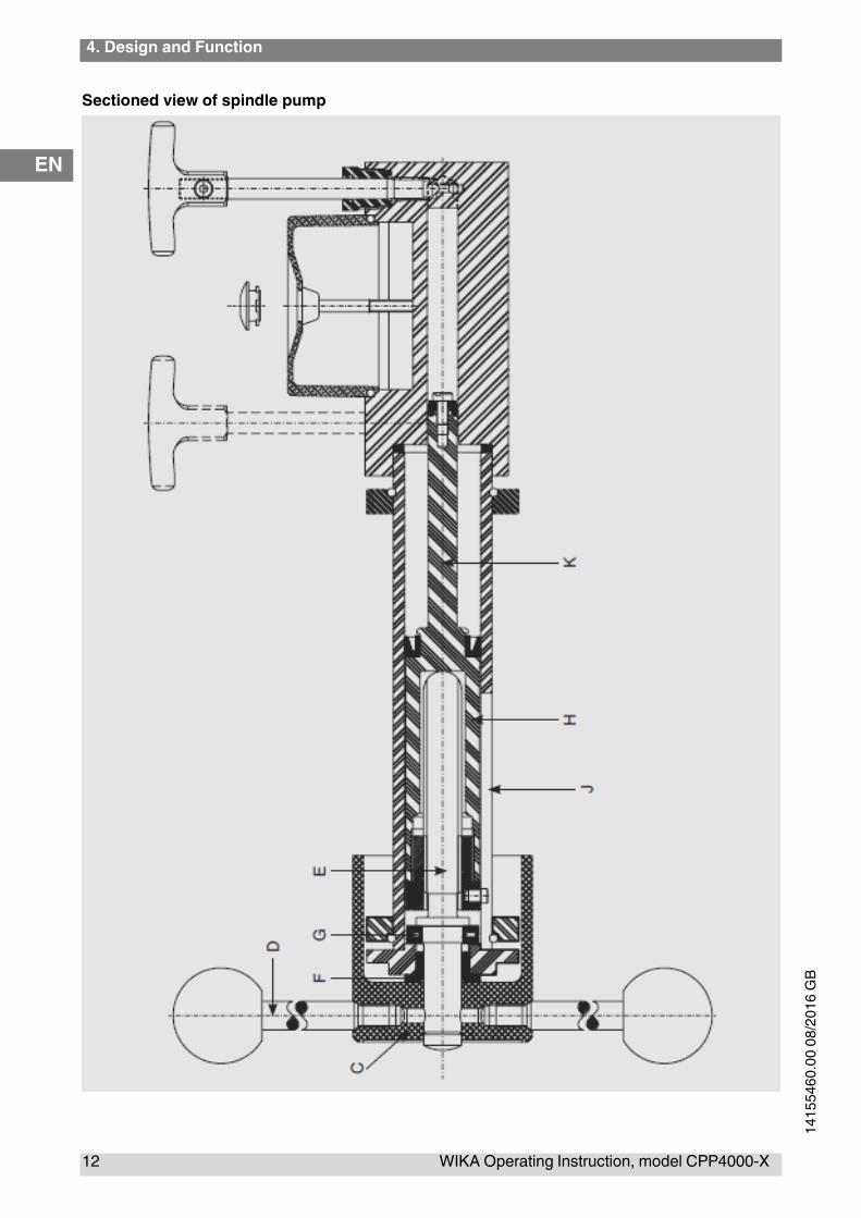
Sectioned view of spindle pump

3. Design and Function
WIKA Operating Instruction, CPP4000-X 13
EN
14
15
54
60
.0 0
8/2
01
6 G
B
3.3.1 Spindle pump
The spindle pump is bolted to the reservoir/high pressure cylinder block fastened to the base unit. A
sectioned view of the pump is shown. The rotating handwheel (C) which is operated by the spokes
(D) is attached to a threaded spindle (E). The spindle is supported in a sintered bearing (F). As the
spindle (E) is rotated, it drives a non-rotating ram (E and K) forward, the thrust being taken by a
needle thrust bearing (G). The large diameter of the ram (H) in the barrel of the pump (J) primes the
pressure system and provides the low pressure up to approximately 140 bar (2,000 lb/in²). The small
diameter of the ram (K) in the reservoir/high pressure cylinder block provides the higher test
pressures up to 4,000 bar (60,000 lb/in²).
3.3.2 Reservoir
A liquid reservoir is provided on the top of reservoir/high pressure cylinder block. The reservoir is
provided with a translucent cover to enable the reservoir level to be monitored. A plug in the middle
of the reservoir cover enables the reservoir to be filled or topped up (the plug is removed whilst the
test pump is in use). The reservoir contains enough liquid (approximately 150 cm³) to enable
normal operation of the test pump to be carried out.
Low pressure ram displacement = 60 cm³
High pressure ram displacement = 6 cm³
3.3.3 Control valves
Two control valves are provided on the top of reservoir/high pressure cylinder block. The valve
mechanisms are built into the reservoir/high pressure cylinder block and they control the flow of
liquid through internal drillings in the reservoir/high pressure cylinder block. The rear valve is
referred to as valve A and is used to control the output from the high-pressure ram of the spindle
pump. The front valve is referred to as valve B and is used to control the flow of liquid to and from
the reservoir.
3.3.4 Connection blocks
Pressure supply pipes from the spindle pump are terminated at two pressure blocks mounted on
the base unit. The pressure blocks are fitted with threaded bosses projecting up through the cover
plate of the base unit. These threaded bosses enable the delivered test connections to be directly
screwed on to them, and it is also possible, using threaded adapters, to connect the various sizes
of measuring instrument connections. Oil cups are fitted to the unit cover around the threaded
bosses of the connection blocks to catch any oil drips from the gauge stand during gauge fitting and
removal.
3.4 Function
Operation of the hydraulic comparison test pump is controlled by the two valves A and B on the top
of the reservoir/high pressure cylinder block. When initially priming the system valves A and B are
opened to fill the system with oil from the reservoir. Valve B is then closed with valve A left open and
the spindle pump operated to provide the lower test pressures. To provide the higher pressures

4. Design and Function
14 WIKA Operating Instruction, model CPP4000-X
EN
14
15
54
60
.00
08
/20
16
GB
valve A is closed to seal off the test circuit from the low pressure part of the spindle pump and valve
B is opened to allow the liquid in the low pressure part of the spindle pump to return to the reservoir
as the pump is operated. This ensures that the pump can be operated without having to put large
forces on the spindle pump handwheel. To release the test pressure the spindle pump is wound out
and valve A is opened.

5. Transport, packaging and storage
WIKA Operating Instruction, CPP4000-X 15
EN
14
15
54
60
.0 0
8/2
01
6 G
B
4. Transport, packaging and storage
4.1 Transport
Check the model CPP4000-X hydraulic comparison test pump for any damage that may have been
caused by transport.
Obvious damage must be reported immediately.
CAUTION!
Damage through improper transport
With improper transport, a high level of damage to property can occur.
▶ When unloading packed goods upon delivery as well as during internal
transport, proceed carefully and observe the symbols on the packaging.
▶ With internal transport, observe the instructions in chapter 4.2 “Packaging and
storage”.
4.2 Packaging and storage
Do not remove packaging until just before mounting.
Keep the packaging as it will provide optimum protection during transport (e.g. change in installation
site, sending for repair).
Permissible conditions at the place of storage:
■ Storage temperature: -10 ... 50 °C
■ Humidity: 35 ... 85 % relative humidity (no condensation)
Avoid exposure to the following factors:
■ Direct sunlight or proximity to hot objects
■ Mechanical vibration, mechanical shock (putting it down hard)
■ Soot, vapour, dust and corrosive gases
■ Potentially explosive environments, flammable atmospheres
■ Corrosive liquids
Store the model CPP4000-X hydraulic comparison test pump in its original packaging in a location
that fulfils the conditions listed above. If the original packaging is not available, pack and store the
instrument as described below:
1. Wrap the instrument in an antistatic plastic film.
2. Place the instrument, along with shock-absorbent material, in the packaging.
3. If stored for a prolonged period of time (more than 30 days), place a bag, containing a desiccant,
inside the packaging.
6. Commissioning, operation
16 WIKA Operating Instruction, model CPP4000-X
EN
14
15
54
60
.00
08
/20
16
GB
5. Commissioning, operation
5.1 Unpacking the hydraulic comparison test pump
As soon as possible after delivery open the packaging of the hydraulic comparison test pump and
check that you have all the items detailed in the packing list (see chapter 3.2 “Scope of delivery”). As
you are unpacking the items, examine them for signs of damage or breakage during transit.
If any items are missing get in touch immediately with DH-Budenberg/WIKA to inform us of the
shortage.
5.2 Environmental requirement
When siting the hydraulic comparison test pump not in a temperature controlled laboratory, look for
an area that satisfies the following criteria as much as possible:
■ A constant temperature area free from draughts and sources of heat or cold
■ An area free from noise and vibration, constantly used pathways
■ A clean dry area free from corrosive liquids or vapours
A strong, stable, level table or workbench with the capability of supporting the system with sufficient
space to operate is required.
5.3 Assembly of base units Fastening base to bench
The base is to be mounted on a firm, level table or bench about 0.9 m high. The centre line of the
front adjustable feet of the unit should be about 40 mm from the front edge of the bench to allow
adequate clearance for the handwheel.
1. Mark the position of the adjustable feet of the unit on the top of the bench.
2. Position a level plate at the centre of each of the adjustable feet of the unit and screw the plate to
the bench to ensure that the hydraulic comparison test pump is rigid.
3. Fit the base unit on the bench with the adjustable feet on the level plates and the handwheel
shaft projecting over the front of the bench.
4. Screw in the four handwheel spokes into the hub.
5. Using the spirit level provided, level the test pump by adjusting the four knurled feet.
5.4 Assembly
5.4.1 Connection of the test item and the reference measuring instrument
The instrument to be tested and the reference measuring instrument are inserted into the two test
connections and can be oriented. It doesn’t matter which port is used for which instrument.
Information
To calibrate instruments with a rear-mount connection, an angular connector is
available as an accessory.

5. Commissioning, operation
WIKA Operating Instruction, CPP4000-X 17
EN
14
15
54
60
.0 0
8/2
01
6 G
B
WARNING
Check that the seals in the test connections are seated correctly and are not worn.
Replace them if necessary.
It is important that any instrument that is to be connected is clean inside.
Information
As standard, the test connections are G ½ female.
5.4.2 Filling the base unit with liquid
1. Remove filler plug from reservoir by prising plug out. (This plug should be left out whilst in use).
2. Open valves A and B.
3. Wind spindle pump handle fully clockwise.
4. Fill reservoir with appropriate liquid. Use the oil supplied or an approved substitute for oil
systems. Do not use other liquids. Castor based oils, Skydrol, solvents or similar liquids will
attack the seals fitted in the test pump.
5. Wind spindle pump handle fully anti-clockwise.
6. Top up reservoir if necessary.
Wear safety goggles!
Protect eyes from flying particles and liquid splashes.
5.4.3 Post assembly test
1. Carry out a test calibration of a known instrument (see chapter 5.5 “Procedure”) to ensure that
the unit is working correctly.
2. Release the pressure and remove the test instrument.
Information
To remove the instrument from the system, use the appropriate size of spanners on
the top section of the pressure connection and on the body of the instrument only.
Ensure that the lower part of the pressure connection is not rotated as this may
release it from the base.
3. The system is now ready for use.
Information
When testing equipment with a large volume, the capacity of the spindle pump (65
cm³) may be insufficient to reach the pressure required. In this case, the equipment
should be filled as far as possible with the liquid before connecting it to the system,
so that the displacement needed is reduced.
Dirty or chemically contaminated test items should not be fitted as they contaminate
the system unless they are first cleaned.

6. Commissioning, operation
18 WIKA Operating Instruction, model CPP4000-X
EN
14
15
54
60
.00
08
/20
16
GB
Wear safety goggles!
Protect eyes from flying particles and liquid splashes.
5.5 Procedure
1. Fit instrument to be tested to a test connection.
2. Connect the reference measuring instrument to the other test connection.
5.5.1 To apply pressure
For pressures up to 140 bar (2,000 lb/in²)
1. Close valve B (valve A remaining open).
2. Wind spindle pump handle clockwise. This will generate pressure up to approximately 140 bar
or 2,000 lb/in², as handle is wound in. When handle becomes stiff to rotate this will indicate that
the pressure limit for this range has been reached.
For pressures above 140 bar (2,000 lb/in²)
1. Close Valve A and open valve B.
2. Continue to wind spindle pump handle clockwise. This will generate pressure up to
approximately 4,000 bar or 60,000 lb/in².
5.5.2 During calibration
Increase the pressure via the spindle pump in the clockwise direction, or use the fine adjustment to
approach the individual calibration points.
The display of the pressure measuring instrument being tested can be compared with the reference
measuring instrument at the individual calibration points.
Information
If there are still small air particles within the system, the generated test pressure will
initially drop and must be readjusted accordingly.
With higher pressures, a longer waiting time than with lower pressures should be
expected until the steady-state condition has been reached.
5.6 Completion
1. After the test is finished wind spindle pump handle anti-clockwise to lower pressure.
2. Gently open valve A or B to release residual pressure.
3. Ensure that both valves A and B are fully open.
4. Remove device under test.
The system is now ready for another test and any residual pressure is relieved.
5. Commissioning, operation
WIKA Operating Instruction, CPP4000-X 19
EN
14
15
54
60
.0 0
8/2
01
6 G
B
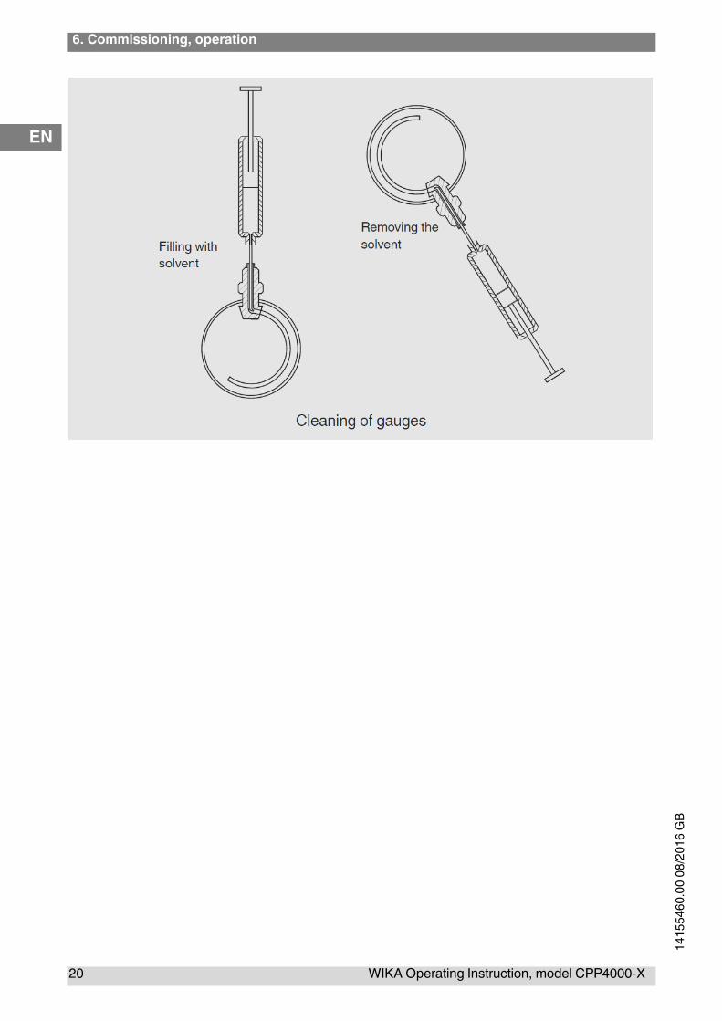
5.7 Cleaning gauges
This cleaning/degreasing process is only suitable for use with pressure gauges with either phosphor
bronze, beryllium copper, Monel or stainless steel Bourdon tubes in the form of a “C”.
It is not advisable to degrease pressure gauges with steel Bourdon tubes since a very small amount
of corrosion on the bore of a Bourdon tube can cause inaccuracies of reading and early failure of the
tube.
Wear safety goggles!
Protect eyes from flying particles and liquid splashes.
This method of cleaning is not suitable for use with pressure gauges which are fitted with coiled
Bourdon tubes, nor any gauges which are to be used on oxygen, as complete removal of oil is not
assured. Please contact DH-Budenberg/WIKA.
Equipment
This consists of a syringe and a special needle with the point bent through 90°.
Instructions
1. Fill syringe with solvent (suitable cold degreasing liquid).
2. With gauge connection pointing upwards put needle into connection and insert by feel the point
into the hole leading to the tube.
3. Inject the solvent. Ideally the tube should be half full.
4. Shake gauge in various attitudes to agitate solvent.
5. Suck solvent back into syringe, holding gauge at an angle.
6. Check that solvent removed is clean. To be sure that all oil has been removed, repeat cleaning
process until solvent removed from gauge is as clean as that put in.
6. Commissioning, operation
20 WIKA Operating Instruction, model CPP4000-X
EN
14
15
54
60
.00
08
/20
16
GB

6. Faults
WIKA Operating Instruction, CPP4000-X 21
EN
14
15
54
60
.0 0
8/2
01
6 G
B
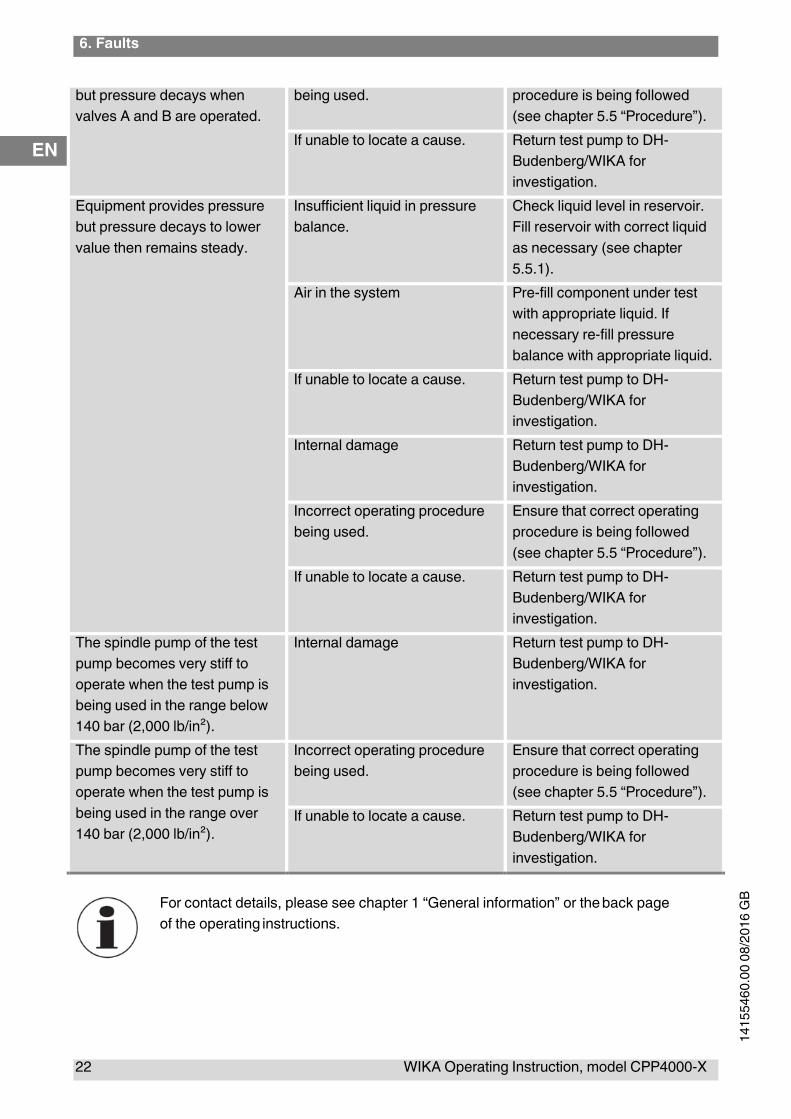
6. Faults
Faults Causes Measures
Equipment does not provide
any output pressure.
No liquid in the test pump. Check that the test pump is
filled with liquid. Fill the
equipment with fluid as
necessary. See chapter 5.4.2
“Filling the equipment with
liquid”.
Valve B is open. Close valve B and try again.
Component being tested has a
large volume.
Pre-fill component with liquid
before test.
Missing or damaged liquid
seals shown by signs of
unexplained liquid leaks.
Examine seals on equipment to
ensure they are fitted correctly
and are undamaged. Replace
as necessary.
Valve B handwheel
disconnected from spindle.
Examine valve B. Tighten up
nut securing handwheel to
spindle as necessary.
Valve B assembly or valve seat
damaged.
Examine condition of valve B
and valve seat. Replace valve
assembly or return test pump to
DH-Budenberg/WIKA for
overhaul as necessary.
If unable to locate a cause. Return test pump to DH-
Budenberg/WIKA for
investigation.
Equipment provides pressure
but pressure decays to zero
Incorrect operating procedure
being used.
Ensure that correct operating
procedure is being followed
(see chapter 5.5 “Procedure”).
Missing or damaged liquid
seals shown by signs of
unexplained liquid leaks.
Examine seals on equipment to
ensure they are fitted correctly
and are undamaged. Replace
as necessary.
Valve A or Valve B valve
assembly or valve seat
damaged.
Examine condition of valves A
and B and valve seat. Replace
valve assembly or return test
pump to DH-Budenberg/WIKA
for overhaul as necessary.
If unable to locate a cause. Return test pump to DH-
Budenberg/WIKA for
investigation.
Equipment provides pressure Incorrect operating procedure Ensure that correct operating
6. Faults
22 WIKA Operating Instruction, model CPP4000-X
EN
14
15
54
60
.00
08
/20
16
GB
but pressure decays when
valves A and B are operated.
being used. procedure is being followed
(see chapter 5.5 “Procedure”).
If unable to locate a cause. Return test pump to DH-
Budenberg/WIKA for
investigation.
Equipment provides pressure
but pressure decays to lower
value then remains steady.
Insufficient liquid in pressure
balance.
Check liquid level in reservoir.
Fill reservoir with correct liquid
as necessary (see chapter
5.5.1).
Air in the system Pre-fill component under test
with appropriate liquid. If
necessary re-fill pressure
balance with appropriate liquid.
If unable to locate a cause. Return test pump to DH-
Budenberg/WIKA for
investigation.
Internal damage Return test pump to DH-
Budenberg/WIKA for
investigation.
Incorrect operating procedure
being used.
Ensure that correct operating
procedure is being followed
(see chapter 5.5 “Procedure”).
If unable to locate a cause. Return test pump to DH-
Budenberg/WIKA for
investigation.
The spindle pump of the test
pump becomes very stiff to
operate when the test pump is
being used in the range below
140 bar (2,000 lb/in²).
Internal damage Return test pump to DH-
Budenberg/WIKA for
investigation.
The spindle pump of the test
pump becomes very stiff to
operate when the test pump is
being used in the range over
140 bar (2,000 lb/in²).
Incorrect operating procedure
being used.
Ensure that correct operating
procedure is being followed
(see chapter 5.5 “Procedure”).
If unable to locate a cause. Return test pump to DH-
Budenberg/WIKA for
investigation.
For contact details, please see chapter 1 “General information” or the back page
of the operating instructions.
6. Faults
WIKA Operating Instruction, CPP4000-X 23
EN
14
15
54
60
.0 0
8/2
01
6 G
B
CAUTION!
If faults cannot be eliminated by means of the measures listed above, shut down the
test pump immediately, and ensure that pressure is no longer present, and secure the
instrument from being put back into operation inadvertently.
In this case, contact the manufacturer.
If a return is needed, please follow the instructions given in chapter 8.1 “Return”.
7. Maintenance, cleaning and servicing
24 WIKA Operating Instruction, model CPP4000-X
EN
14
15
54
60
.00
08
/20
16
GB
7. Maintenance, cleaning and servicing
7.1 Periodic maintenance
Repairs must only be carried out by the manufacturer.
Cleaning the units and checking the liquid levels is the only periodic maintenance required. With
normal use, no further maintenance should be necessary. If required, the system can be returned to
the manufacturer for re-conditioning.
Fluids, which attack ABS, should be used with caution. Continual immersion of the
cover in such fluids will cause deterioration. Spillage’s should be wiped off
immediately.
7.2 Corrective maintenance
7.2.1 General
This section contains details on stripping the unit and replacing the spare parts which are listed (see
chapter 10 “Accessories”). The component identification numbers in brackets in each procedure
refer to the following figure.

7. Maintenance, cleaning and servicing
WIKA Operating Instruction, CPP4000-X 25
EN
14
15
54
60
.0 0
8/2
01
6 G
B
7. Maintenance, cleaning and servicing
26 WIKA Operating Instruction, model CPP4000-X
EN
14
15
54
60
.00
08
/20
16
GB
7.2.2 Removing the cover
1. Drain as much oil as possible from the test pump by turning the spindle pump fully clockwise and
using a drain screwed into the test connection.
2. Remove the oil cups by levering upwards carefully.
3. Slacken the socket set screw using a 3 mm hexagon wrench key and remove both handwheels.
4. Remove the four cover retaining screws and lift off the cover.
7.2.3 Reservoir seals
1. Unscrew two screws and remove the reservoir cover
2. Remove the O-ring seal (6) from the recess and the Seloc seal (7) from the screws.
3. On replacement ensure all sealing faces are absolutely clean and do not overtighten screws.
7.2.4 Valve seals
1. Unscrew the gland nut.
2. Unscrew the valve spindle and remove the bonded seal.
3. Slide gland nut off spindle.
4. Using a suitable hooked tool remove the O-ring seal (9) from the bore of the gland nut. Renew
O-ring and bonded seal (10).
5. On replacement ensure that O-ring is correctly located in the groove and all sealing faces are
clean. Remove all burrs from spindle.
7.2.5 Spindle pump
1. Using a 4 mm hexagon wrench key unscrew the six socket head cap screws secur- ing the hub
locating plate. (These are positioned inside the recess in the back of the aluminium hub).
2. By carefully pulling the hub the complete ram assembly can now be withdrawn from the barrel
(During this operation a container is required beneath the barrel to catch any liquid).
3. Unscrew the ram from the hub assembly.
4. The high pressure seal (12A&B) and low pressure seal (15) can now be replaced. Before fitting
the new seals check the ram is not scored on the locating diameters.
5. At this point the hub assembly should be checked for excess play indicating wear in the bearing
and for wear in the screwed spindle and nut. If any wear is found it will be
necessary to dismantle the hub assembly.
6. Check the bore of the block assembly (11) is not badly scored or pitted. If a replacement is
required this item is supplied complete with valves. The block is attached to the base by socket
head cap screws.
7. Re-assembly is a straightforward reversal of the above procedures.
On assembly care should be taken to align the ram to prevent bending, or damage
to the seals. Excessive force should not be used.
The socket head cap screws are not spaced equally around the locating flanges
so check hole alignment before inserting screws.
7. Maintenance, cleaning and servicing
WIKA Operating Instruction, CPP4000-X 27
EN
14
15
54
60
.0 0
8/2
01
6 G
B
7.2.6 Hub assembly
1. Unscrew the ram from the spindle. NOTE: left hand thread.
2. Unscrew the spokes from the hub.
3. Knock out the spring pin (1), found at the bottom of one of the tapped spoke holes in the hub,
using a punch 6 mm dia. Pull off hub.
4. The hub locating plate and thrust bearing can now be removed from the spindle.
5. If the flanged bush (2) is to be renewed, it should be pressed out of the locating plate and a new
one pressed in squarely.
6. The thrust bearing (3) is renewed as a complete assembly.
7. The nut, pin and spindle sub-assembly (4) can only be replaced as a matched pair. Unscrew the
nut from the ram, gripping in a soft jaw vice and screw in the new nut.
8. Assemble the thrust bearing, locating plate and hub on to the spindle, lubricating with
molybdenum disulphide grease.
9. Clamp these items together to eliminate end play and re-assemble spring pin. If using new
spindle drill through 6.3 mm diameter to fit spring pin (1).
10. Lubricate the thread with molybdenum disulphide grease and screw into ram nut.
7.3 Cleaning
7.3.1 Cleaning the unit and checking the liquid levels.
Oil operation
Keep the system clean and free from spilt oil. Wipe out the oil cups under the gauge stands as
necessary. Do not use any cleansing solvents as they may damage the seals.
Ensure that the reservoir contains sufficient liquid to carry out any calibrations required. If necessary
top up the reservoir with the same liquid that is already being used. Do not mix various types or
brands of liquid in the pressure balance.
If the oil in the test pump becomes dirty, attach a drain to the test connection and use the spindle
pump to flush through clean oil. (An angle connection is suitable). The spindle pump should be
turned fully clockwise before starting.
Wear safety goggles!
Protect eyes from flying particles and liquid splashes.
For information on returning the instrument see chapter 8.1 “Return”.
.

8. Dismounting, return and disposal
28 WIKA Operating Instruction, model CPP4000-X
EN
14
15
54
60
.00
08
/20
16
GB
8. Dismounting, return and disposal
WARNING!
Residual media on the hydraulic comparison test pump can result in a risk to persons,
the environment and the equipment. Take sufficient precautionary measures.
8.1 Return
WARNING!
Physical injuries and damage to property and the environment through
residual media
Residual media in the dismounted instrument can result in a risk to persons, the
environment and equipment.
▶ With hazardous substances, include the material safety data sheet for the
corresponding medium.
▶ Clean the instrument, see chapter 7.3 “Cleaning”.
WARNING!
Strictly observe the following when shipping the instrument:
All instruments delivered to DH-Budenberg/WIKA must be free from any kind of
hazardous substances (acids, bases, solutions etc.).
When returning the instrument, use the original packaging or a suitable transport packaging.
To avoid damage:
1. Wrap the instrument in an antistatic plastic film.
2. Place the instrument along with shock-absorbent material in the packaging. Place shock-
absorbent material evenly on all sides of the transport packaging.
3. If possible, place a bag containing a desiccant inside the packaging.
4. Label the shipment as carriage of a highly sensitive measuring instrument.
Information on returns can be found under the heading “Service” on our local
website.
8.2 Disposal
Incorrect disposal can put the environment at risk.
Dispose of instrument components and packaging materials in an environmentally compatible way
and in accordance with the country-specific waste disposal regulations
This marking on the instruments indicates that they must not be disposed of in
domestic waste. The disposal is carried out by return to the manufacturer or by the
corresponding municipal authorities (see EU directive 2012/19/EU).
.
10. Specifications
WIKA Operating Instruction, CPP4000-X 29
EN
14
15
54
60
.0 0
8/2
01
6 G
B
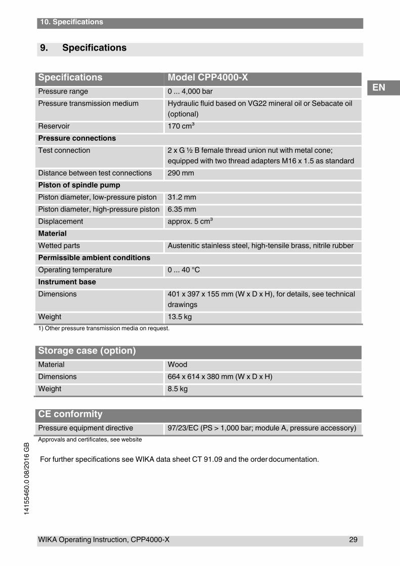
9. Specifications
Specifications Model CPP4000-X
Pressure range 0 ... 4,000 bar
Pressure transmission medium Hydraulic fluid based on VG22 mineral oil or Sebacate oil
(optional)
Reservoir 170 cm³
Pressure connections
Test connection 2 x G ½ B female thread union nut with metal cone;
equipped with two thread adapters M16 x 1.5 as standard
Distance between test connections 290 mm
Piston of spindle pump
Piston diameter, low-pressure piston 31.2 mm
Piston diameter, high-pressure piston 6.35 mm
Displacement approx. 5 cm³
Material
Wetted parts Austenitic stainless steel, high-tensile brass, nitrile rubber
Permissible ambient conditions
Operating temperature 0 ... 40 °C
Instrument base
Dimensions 401 x 397 x 155 mm (W x D x H), for details, see technical
drawings
Weight 13.5 kg
1) Other pressure transmission media on request.
Storage case (option)
Material Wood
Dimensions 664 x 614 x 380 mm (W x D x H)
Weight 8.5 kg
CE conformity
Pressure equipment directive 97/23/EC (PS > 1,000 bar; module A, pressure accessory)
Approvals and certificates, see website
For further specifications see WIKA data sheet CT 91.09 and the order documentation.
9. Specifications
30 WIKA Operating Instruction, model CPP4000-X
EN
14
15
54
60
.00
08
/20
16
GB
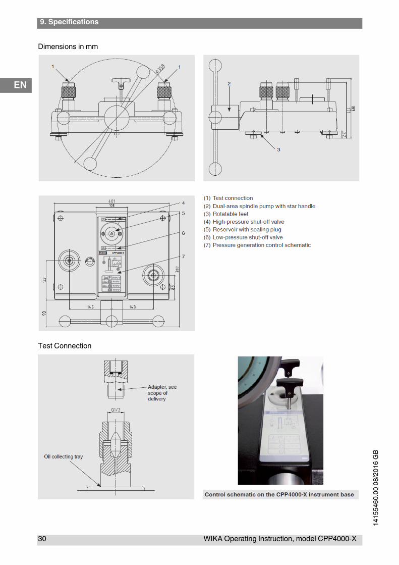
Dimensions in mm
Test Connection
10. Accessories
WIKA Operating Instruction, CPP4000-X 31
EN
14
15
54
60
.0 0
8/2
01
6 G
B
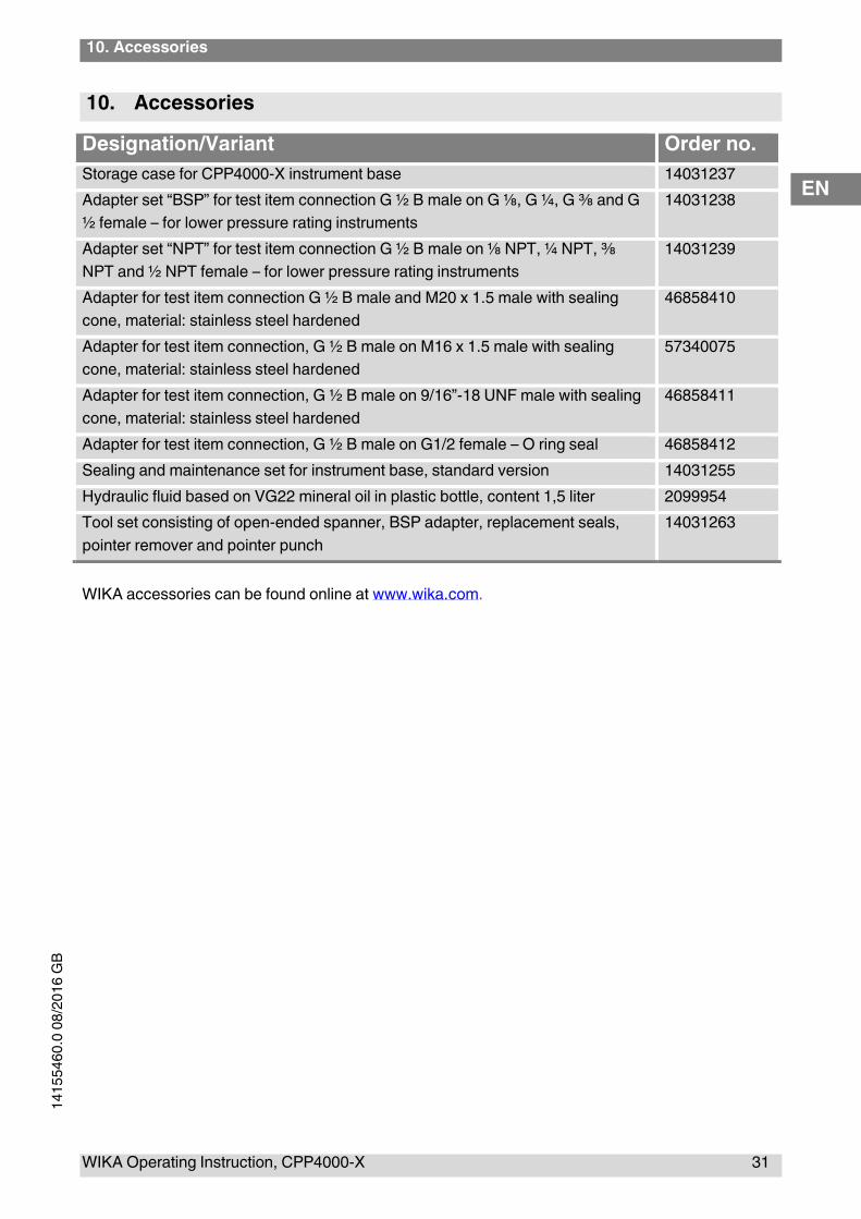
10. Accessories
Designation/Variant Order no.
Storage case for CPP4000-X instrument base 14031237
Adapter set “BSP” for test item connection G ½ B male on G ⅛, G ¼, G ⅜ and G
½ female – for lower pressure rating instruments
14031238
Adapter set “NPT” for test item connection G ½ B male on ⅛ NPT, ¼ NPT, ⅜
NPT and ½ NPT female – for lower pressure rating instruments
14031239
Adapter for test item connection G ½ B male and M20 x 1.5 male with sealing
cone, material: stainless steel hardened
46858410
Adapter for test item connection, G ½ B male on M16 x 1.5 male with sealing
cone, material: stainless steel hardened
57340075
Adapter for test item connection, G ½ B male on 9/16”-18 UNF male with sealing
cone, material: stainless steel hardened
46858411
Adapter for test item connection, G ½ B male on G1/2 female – O ring seal 46858412
Sealing and maintenance set for instrument base, standard version 14031255
Hydraulic fluid based on VG22 mineral oil in plastic bottle, content 1,5 liter 2099954
Tool set consisting of open-ended spanner, BSP adapter, replacement seals,
pointer remover and pointer punch
14031263
WIKA accessories can be found online at www.wika.com.