operating instructions hart - endress+hauser · liquisys m cxm223/253 hart wiring endress+hauser 9...
TRANSCRIPT

BA208C/07/en/10.05
51517596
Operating Instructions
HART
Field Communication with Liquisys M CXM223/253
6

Endress+Hauser
Brief operating instructions
This explains how to use these Operating Instructions to commission your transmitter quickly and
safely:
Safety instructions
→ Page 4 ff.
→ Page 5
General safety instructions
Expanation of the warning symbols
You can find special instructions at the appropriate position in the chapter in question. The
positions are indicated with the icons Warning #, Caution " and Note !.
Æ
Installation
→ Page 7 The system architecture is explained here.
Æ
Wiring
→ Page 8 ff. Here you can find out how to connect the transmitter.
Æ
Operation
→ Page 11
→ Page 12 ff.
→ Page 18 ff.
The display and operating elements are described here.
Here you can find out how to use Commuwin II.
The commands are described here.
Æ
Maintenance
→ Page 24 Here you can find the available accessories.
→ Page 25 ff. If faults occur during operation, use the error codes to localize and eliminate the cause.
Æ
Technical data
→ Page 30 Output, power consumption etc.
Æ
Index
→ Page 31 You can find important terms and keywords here. Use the keyword index to find the information
you need quickly and efficiently.

Liquisys M CXM223/253 HART
Endress+Hauser 3
Table of contents
1 Safety instructions . . . . . . . . . . . . . . . . 4
1.1 Designated use . . . . . . . . . . . . . . . . . . . . . . . . . . . . 4
1.2 Installation, commissioning and operation . . . . . . . . 4
1.3 Operational safety . . . . . . . . . . . . . . . . . . . . . . . . . . 4
1.4 Notes on safety icons and symbols . . . . . . . . . . . . . . 5
2 Identification . . . . . . . . . . . . . . . . . . . . 6
2.1 Instrument designation . . . . . . . . . . . . . . . . . . . . . . 6
2.2 Scope of delivery . . . . . . . . . . . . . . . . . . . . . . . . . . . 6
2.3 Certificates and approvals . . . . . . . . . . . . . . . . . . . . 6
3 Installation . . . . . . . . . . . . . . . . . . . . . . 7
3.1 System equipment . . . . . . . . . . . . . . . . . . . . . . . . . . 7
3.2 Post-installation check . . . . . . . . . . . . . . . . . . . . . . . 7
4 Wiring . . . . . . . . . . . . . . . . . . . . . . . . . 8
4.1 Electrical connection . . . . . . . . . . . . . . . . . . . . . . . 8
4.2 Post-connection check . . . . . . . . . . . . . . . . . . . . . . 10
5 Operation . . . . . . . . . . . . . . . . . . . . . . 11
5.1 Display and operating elements . . . . . . . . . . . . . . . 11
5.2 Operation via HART handheld terminal
DXR275/DXR375 . . . . . . . . . . . . . . . . . . . . . . . . . 11
5.3 Operation via FieldCare . . . . . . . . . . . . . . . . . . . . . 12
5.4 Operation via Commuwin II . . . . . . . . . . . . . . . . . 12
5.5 HART commands . . . . . . . . . . . . . . . . . . . . . . . . . 18
6 Commissioning. . . . . . . . . . . . . . . . . . 23
6.1 Function check . . . . . . . . . . . . . . . . . . . . . . . . . . . 23
6.2 Setting of device address . . . . . . . . . . . . . . . . . . . . 23
7 Maintenance. . . . . . . . . . . . . . . . . . . . 24
8 Accessories. . . . . . . . . . . . . . . . . . . . . 24
9 Troubleshooting . . . . . . . . . . . . . . . . . 25
9.1 Device status / error messages . . . . . . . . . . . . . . . . 25
9.2 Error messages Liquisys M CPM2X3 . . . . . . . . . . . 25
9.3 Error messages Liquisys M CLM2X3 . . . . . . . . . . . 26
9.4 Error messages Liquisys M COM2X3 . . . . . . . . . . . 27
9.5 Error messages Liquisys M CUM2X3 . . . . . . . . . . . 28
9.6 Error messages Liquisys M CCM2X3 . . . . . . . . . . . 29
10 Technical data . . . . . . . . . . . . . . . . . . 30
10.1 Output . . . . . . . . . . . . . . . . . . . . . . . . . . . . . . . . . 30
10.2 Power supply . . . . . . . . . . . . . . . . . . . . . . . . . . . . 30
10.3 Display and user interface . . . . . . . . . . . . . . . . . . . 30
Index . . . . . . . . . . . . . . . . . . . . . . . . . 31

Safety instructions Liquisys M CXM223/253 HART
4 Endress+Hauser
1 Safety instructions
1.1 Designated use
These Operating Instructions were specially designed for use with transmitters from the
Liquisys M CXM223/253 family. They contain specific information on instruments equipped with
the HART interface (Highway Addressable Remote Transducer).
The HART interface allows the device to be operated:
• via the handheld terminal DXR275 / DXR375
• via the operating program Commuwin II at a PC
• via FieldCare (Plant-Asset-Management-Tool) at a PC
Any other use than the one described here compromises the safety of persons and the entire
measuring system and is, therefore, not permitted.
The manufacturer is not liable for damage caused by improper or non-designated use.
1.2 Installation, commissioning and operation
Please note the following items:
• Installation, commissioning, operation and maintenance of the measuring system must only be
carried out by trained technical personnel.
The technical personnel must be authorised for the specified activities by the system operator.
• Electrical connection must only be carried out by a certified electrician.
• Technical personnel must have read and understood these Operating Instructions and must
adhere to them.
• Before commissioning the entire measuring point, check all the connections for
correctness. Ensure that electrical cables and hose connections are not damaged.
• Do not operate damaged products and secure them against unintentional
commissioning. Mark the damaged product as being defective.
• Measuring point faults may only be rectified by authorised and specially trained
personnel.
• If faults can not be rectified, the products must be taken out of service and secured against
unintentional commissioning.
• Repairs not described in these Operating Instructions may only be carried out at the
manufacturer’s or by the service organisation.
1.3 Operational safety
The transmitter has been designed and tested according to the state of the art and left the factory in
perfect functioning order.
Relevant regulations and European standards have been met.
As the user, you are responsible for complying with the following safety conditions:
• Installation instructions
• Local prevailing standards and regulations.
Ex systems have an additional Ex documentation which is part of these Operating Instructions (see
also chapter "Scope of delivery").
Immunity to interference
This instrument has been tested for electromagnetic compatibility in industrial use according to
applicable European standards.
Protection against interference as specified above is valid only for an instrument
connected according to the instructions in these Operating Instructions.
Liquisys M CXM223/253 HART Safety instructions
Endress+Hauser 5
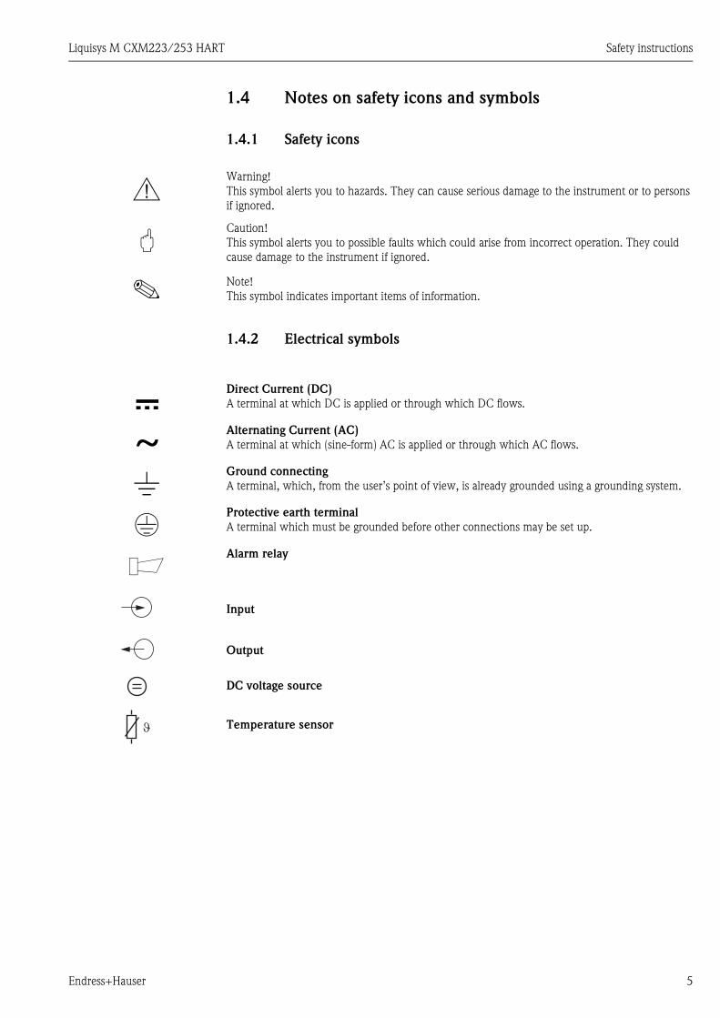
1.4 Notes on safety icons and symbols
1.4.1 Safety icons
1.4.2 Electrical symbols
#Warning!
This symbol alerts you to hazards. They can cause serious damage to the instrument or to persons
if ignored.
"Caution!
This symbol alerts you to possible faults which could arise from incorrect operation. They could
cause damage to the instrument if ignored.
! Note!
This symbol indicates important items of information.
%Direct Current (DC)
A terminal at which DC is applied or through which DC flows.
&Alternating Current (AC)
A terminal at which (sine-form) AC is applied or through which AC flows.
)Ground connecting
A terminal, which, from the user’s point of view, is already grounded using a grounding system.
*Protective earth terminal
A terminal which must be grounded before other connections may be set up.
bAlarm relay
Input
Output
DC voltage source
Temperature sensor

Identification Liquisys M CXM223/253 HART
6 Endress+Hauser
2 Identification
2.1 Instrument designation
Compare the order code on the nameplate (on the transmitter) with the product structure (see
below) and your order.
You can identify the instrument version by the order code on the nameplate.
2.2 Scope of delivery
The scope of delivery comprises:
• 1 transmitter (type and version acc. to the nameplate)
• Installation accessories
• 1 standard Operating Instructions BA193C/07/en (CLM), BA194C/07/en (CPM),
BA199C/07/en (COM), BA200C/07/en (CUM), BA214C/07/en (CCM), BA246C/07/en
(COM F)
• 1 Operating Instructions Field communication with HART, BA208C/07/en
• versions with explosion protection for hazardous area zone 2 (ATEX II 3G)
Safety instructions for use in explosion-hazardous areas, XA194C/07/a3
2.3 Certificates and approvals
Declaration of conformity
The product meets the legal requirements of the harmonized European standards.
The manufacturer confirms compliance with the standards by affixing the 4 symbol.
Explosion protection for Zone 2
a0004971
Fig. 1: Example of a nameplate
Version Approval
CXM253-..6... ATEX II 3G EEx nA[L] IIC T4
CXM253-..4...
CXM223-..4...
CXM223-..6...
ATEX II 3G [EEx nAL] IIC
131085-4D
order codeserial no. /codes
CPM 253-PS1515276944pH 0 … 14 +/-1500 mV-50 … 150°C0/4 … 20 mA230 VAC 50/60 Hz 7.5 VA
-10 … +55°CIP 65
0/4 … 20 mA
- 8732
prot. class ambient temp.
output 1 output 2mains
meas. rangetemperature
3472
LIQUISYS MpH / Redox
Made in Germany, D-70839 Gerlingen

Liquisys M CXM223/253 HART Installation
Endress+Hauser 7
3 Installation
3.1 System equipment
A complete system architecture comprises:
• Transmitter Liquisys M CXM223 or CXM253
• HART handheld terminal DXR275/DXR375
• HART modem Commubox FXA191
• PC with operating program FieldCare or Commuwin II
• Recorder
a0004972
Fig. 2: System architecture Liquisys M CXM223/253 HART
3.2 Post-installation check
• After installation, check the transmitter for damage.
• Check whether the transmitter is protected against moisture and direct sunlight.
HARTHandterminal1 Offline
3 Transfer4 Frequenzg erät5 Extras
2 Online
IO
min.250
1
2
3
5
4
1 Transmitter 4 PC with FieldCare or Commuwin II
2 HART handheld terminal DXR275/DXR375 5 Recorder
3 HART modem Commubox FXA191

Wiring Liquisys M CXM223/253 HART
8 Endress+Hauser
4 Wiring
# Warning!
• The electrical connection must only be carried out by a certified electrician.
• Technical personnel must have read and understood the instructions in this manual and must
adhere to them.
• Ensure that there is no voltage at the power cable before beginning the connection work.
4.1 Electrical connection
4.1.1 Connection options
Users have the following connection options at their disposal:
• Connection via current output 1 (terminals 31 and 32)
• Connection via 4 ... 20 mA circuit
! Note!
The measuring circuit’s minimum load in current output 1 must be 250 Ω.
a0004973
Fig. 3: Electrical connection of Liquisys M CPM253 HART
1 Grounding rail for version IS
pH
/R
ed
ox
(Gla
s)
42
+++++ -----
434154 55 56
NC
SRC
DRN
31
11
12
32
13
PA
/PM
3433
S
RE
F(G
las
/Is
FE
T)
(Is
FE
T)
(Is
FE
T)
NC 938685 94 81 82 NC
51 52 53 57 58 59 47 48 49
pH
Re
do
x
Te
mp
.(o
pt.)
+1
5V
10
mA
YE
WHRD
GN
BN
REL 4SENSOR REL 3 REL 2 REL 1
NC
MainsHilfsenergie
131094-4G
Dig
ital2
Dig
ital1
11 13
12
L1+
N-
(AC)(DC)
Contacts:max. 2AAC: 250V/500VADC: 30V/60W
+ -23 24
4..2
0m
A
1

Liquisys M CXM223/253 HART Wiring
Endress+Hauser 9
a0004974
Fig. 4: Electrical connection of Liquisys M CPM223 HART
1 Grounding terminal for version IS
4.1.2 Connection of the HART handheld terminal DXR275/DXR375
For operation via handheld terminal you require the HART handheld terminal DXR275/DXR375.
Connect the handheld terminal via current output 1 of the transmitter.
For connecting, please refer also to the documentation issued by the HART Communication
Foundation.
a0004975
Fig. 5: Electrical connection of the HART handheld terminal
BNC: pH/Redox + REF
31 +
Sensor
32 -
33 +
34 -
85 +
86 -
93 +
94 - 42
81 + 43
82 - 41
pHRedox
Temp.(opt.)
+15V10mA
Digital 2
Digital 1
NC
NC
NC
131081-4E
S
REF
PA/PM
12
13
11
YE
WH
GN
RD
BN
SRC (IsFET)
(Glass)
IsFETGlass( )
DRN
Ma
ins
Co
nta
cts
:m
ax
.2
A,A
C:2
50
V/5
00
VA
,D
C:3
0V
/60
W
L1 +
AC DC
N -
REL1
REL2
REL3
REL4
4..20mA
24
23
49
COM
COM
COM
COM
-
+
59
54
55
56
52
51
53
58
57
48
47
131084-4C
1
32 N / L–
25031 L / L+
HARTHandterminal1 Offline
3 Transfer4 Frequenzg erät5 Extras
2 OnlineÔ
IO
5
21
34
1 Current output 1 of the transmitter 4 Other evaluation units or PLC with passive input
2 Power supply 5 HART handheld terminal
3 Shield

Wiring Liquisys M CXM223/253 HART
10 Endress+Hauser
4.1.3 Connection of a PC with operating program
You require a HART modem Commubox FXA191 for connecting a personal computer with
operating program Commuwin II. Connect FXA191 via current output 1 of the transmitter.
For connecting please refer also to the documentation issued by the HART Communication
Foundation.
a0004976
Fig. 6: Electrical connection of Commubox FXA191
! Note!
The Commuwin II and HART handheld terminal DXR275/DXR375 can only be operated
simultaneously if:
• one device is set as the primary master and the other as the secondary master
• neither master is constantly communicating.
4.2 Post-connection check
After the electrical connection, carry out the following checks:
32 N / L–
³ W25031 L / L+
4
RS 2325
6
21
34
1 Current output 1 of the transmitter 4 Other evaluation units or PLC with passive input
2 Power supply 5 PC with operating program
3 Shield 6 HART modem Commubox FXA191
Device condition and specifications Notes
Are the transmitter and cables damaged on the outside? Visual inspection
Electrical connection Notes
Are the mounted cables strain relieved?
Cable run without loops and cross-overs?
Are the signal lines correctly connected in accordance with the wiring
diagram?
Are all the screw terminals tightened?
Are all the cable entries installed, tightened and sealed?

Liquisys M CXM223/253 HART Operation
Endress+Hauser 11
5 Operation
5.1 Display and operating elements
a0004977-en
Fig. 7: Display for active communication via HART interface
Please refer to the standard Operating Instructions for an explanation of the key assignment and the
other icons.
5.2 Operation via HART handheld terminal
DXR275/DXR375
For information on the operation refer to the "Communicator DXR275/DXR375" Operating
Instructions which are supplied with the handheld terminal.
a0005134
Fig. 8: Operating the HART handheld terminal DXR375
1
705pH
R262
Setpoint
Operation Liquisys M CXM223/253 HART
12 Endress+Hauser
5.3 Operation via FieldCare
FieldCare is Endress+Hauser's FDT based Plant Asset Management Tool. It can configure all
intelligent field devices in your plant and supports you in managing them. By using status
information, it also provides a simple but effective means of checking their health.
• Supports Ethernet, HART, PROFIBUS, and in future FOUNDATION Fieldbus etc.
• Operates all Endress+Hauser devices
• Integrates third-party devices such as actuators, I/O systems and sensors supporting the FDT
standard
• Ensures full functionality for all devices with DTMs
• Offers generic profile operation for third-party fieldbus devices that do not have a vendor DTM
! Note!
You will find an installation procedure in the operating instructions "Getting started"
BA027S/04/a4.
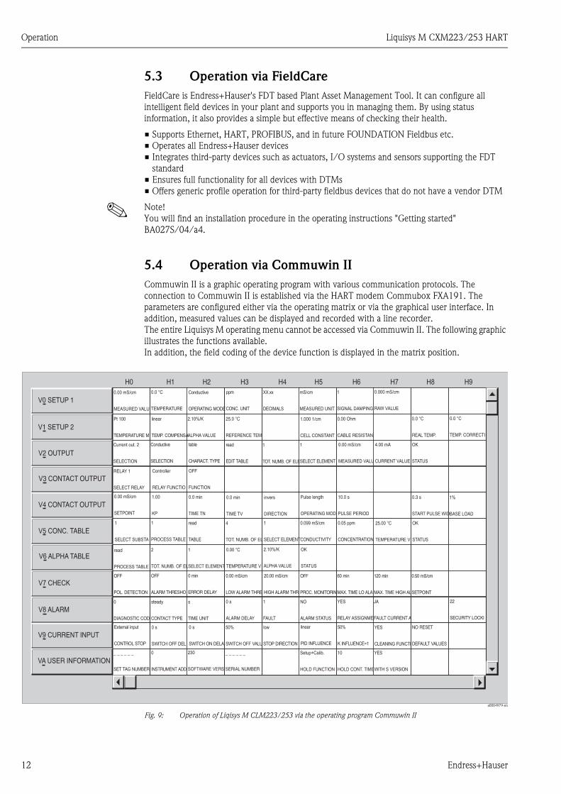
5.4 Operation via Commuwin II
Commuwin II is a graphic operating program with various communication protocols. The
connection to Commuwin II is established via the HART modem Commubox FXA191. The
parameters are configured either via the operating matrix or via the graphical user interface. In
addition, measured values can be displayed and recorded with a line recorder.
The entire Liquisys M operating menu cannot be accessed via Commuwin II. The following graphic
illustrates the functions available.
In addition, the field coding of the device function is displayed in the matrix position.
a0004979-en
Fig. 9: Operation of Liqisys M CLM223/253 via the operating program Commuwin II
0.00 mS/cm
MEASURED VALU
Pt 100
TEMPERATURE M
linear
TEMP. COMPENSA
2.10%/K
ALPHA VALUE
2.10%/K
ALPHA VALUE
25.0 °C
REFERENCE TEM
1.000 1/cm
CELL CONSTANT
0.00 Ohm
CABLE RESISTAN
0.0 °C
REAL TEMP.
0.0 °C
TEMP. CORRECTI
0.0 °C
TEMPERATURE
Current out. 2
SELECTION
RELAY 1
SELECT RELAY
0.00 mS/cm
SETPOINT
1
SELECT SUBSTA
read
PROCESS TABLE
0 s
SWITCH OFF DEL
0 s
SWITCH ON DELA
50%
SWITCH OFF VALU
low
STOP DIRECTION
linear
PID INFLUENCE
50%
K INFLUENCE=1
YES
CLEANING FUNCTI
NO RESET
DEFAULT VALUES
_ _ _ _ _ _
SET TAG NUMBER
_ _ _ _ _ _
SERIAL NUMBER
Setup+Calib.
HOLD FUNCTION
10
HOLD CONT. TIME
YES
WITH S VERSION
1
PROCESS TABLE
2
TOT. NUMB. OF EL
4
TOT. NUMB. OF EL
read
TABLE
1
SELECT ELEMENT
1
SELECT ELEMENT
0.099 mS/cm
CONDUCTIVITY
0.05 ppm
CONCENTRATION
25.00 °C
TEMPERATURE V
0.00 °C
TEMPERATURE V
1.00
KP
0.0 min
TIME TN
0.0 min
TIME TV
invers
DIRECTION
Pulse length
OPERATING MOD
10.0 s
PULSE PERIOD
0.3 s
START PULSE WID
1%
BASE LOAD
Controller
RELAY FUNCTIO
OFF
FUNCTION
0.00 mS/cm
MEASURED VALU
4.00 mA
CURRENT VALUE
OK
STATUS
OK
STATUS
OK
STATUS
ppm
CONC. UNIT
Conductive
OPERATING MODE
XX.xx
DECIMALS
mS/cm
MEASURED UNIT
0.000 mS/cm
RAW VALUE
1
SIGNAL DAMPING
V7 CHECK
V8 ALARM
V0 SETUP 1
V1 SETUP 2
V2 OUTPUT
V3 CONTACT OUTPUT
V4 CONTACT OUTPUT
V5 CONC. TABLE
V6 ALPHA TABLE
V9 CURRENT INPUT
VA USER INFORMATION
Conductive
SELECTION
table
CHARACT. TYPE
read
EDIT TABLE
1
TOT. NUMB. OF ELE
1
SELECT ELEMENT
OFF
POL. DETECTION
OFF
ALARM THRESHO
0 min
ERROR DELAY
0.00 mS/cm
LOW ALARM THRE
20.00 mS/cm
HIGH ALARM THR
OFF
PROC. MONITORIN
60 min
MAX. TIME LO ALA
120 min
MAX. TIME HIGH AL
0.50 mS/cm
SETPOINT
0
DIAGNOSTIC COD
steady
CONTACT TYPE
s
TIME UNIT
0 s
ALARM DELAY
1
FAULT
NO
ALARM STATUS
YES
RELAY ASSIGNME
JA
FAULT CURRENT A
22
SECURITY LOCKI
External input
CONTROL STOP
0
INSTRUMENT ADD
230
SOFTWARE VERS
H0 H1 H2 H3 H4 H5 H6 H7 H8 H9

Liquisys M CXM223/253 HART Operation
Endress+Hauser 13
! Note!
• Refer to the Operating Instructions BA124F/00/en for further information on the operation with
Commuwin II.
• Make sure that the current output 1 is operated at 4 ... 20 mA. There is no presetting due to
transmitter operation without HART communication (HART only as upload-download support).
• Remote calibration via the HART interface is not possible.
• All operating fields are accessible via off-line parameter setting, if access code "Yes" is selected in
matrix position V9H2 and V9H3. If there is no compatibility with the actual device status (e.g. no
access code for Plus package), error code E003 is displayed after finishing the download.
Field
coding
Function group VH position
CPM2X3
VH position
CLM2X3
VH position
CUM2X3
VH position
COM2X3
VH position
CCM2X3
- Measured value
display
V0H0 V0H0 V0H0 V0H0 V0H0
- Measured value
display with
temperature in °C
V0H1 V0H1 V0H1 V0H1 V0H1
- Measured value
display in mV
V1H7 - - - -
- Measured value
display uncomp.
- V0H7 - - -
- Measured value
display in FNU
- - V0H7 - -
- Measured value
display in nA
- - - V0H8 -
- Error display V8H0 V8H0 V8H0 V8H0 V8H0
- Editing mode V8H9 V8H9 V8H9 V8H9 V8H9
A Setup 1
A1 V0H2 V0H2 V0H2 V0H2 V0H3
A2 V0H3 V0H3 V0H3 V0H3 V0H4
A3 V0H6 V0H4 V0H4 V0H4 V0H5
A4 V0H5 V0H5 V0H5 V0H5 V0H6
A5 V0H4 V1H5 V0H6 V0H7 V0H7
A6 - V1H6
(kond.)
- V0H6 V0H8
A7 - V0H6 - - V0H9

Operation Liquisys M CXM223/253 HART
14 Endress+Hauser
B Setup 2
B1 V1H0 V1H0 V1H0 V1H0 V1H0
B2 V1H1 V1H1 V1H1 V1H8 V1H1
B3 V1H2 V1H2 V1H2 V1H9 V1H2
B4 V1H8 V1H4 V1H3 - V1H8
B5 V1H9 V1H8 V1H4 - V1H9
B6 - V1H9 V1H5 - -
B7 - V1H3 V1H8 - -
B8 - - V1H9 - -
B9 - - V1H6 - -
Z Current input
Z1 V5H0 V9H0 V6H0 V5H0 V5H0
Z2 V5H1 V9H1 V6H1 V5H1 V5H1
Z3 V5H2 V9H2 V6H2 V5H2 V5H2
Z4 V5H3 V9H3 V6H3 V5H3 V5H3
Z5 V5H4 V9H4 V6H4 V5H4 V5H4
Z6 V5H5 V9H5 V6H5 V5H5 V5H5
Z7 V5H6 V9H6 V6H6 V5H6 V5H6
O Current output
O1 V2H0 V2H0 V2H0 V2H0 V2H0
O2 V2H1 V2H1 V2H1 V2H1 V2H1
O3 V2H2 V2H2 V2H2 V2H2 V2H2
O3x1 V2H3 V2H3 V2H3 V2H3 V2H3
O3x2 V2H4 V2H4 V2H4 V2H4 V2H4
O3x3 V2H5 V2H5 V2H5 V2H5 V2H5
O334 V2H6 V2H6 V2H6 V2H6 V2H6
O335 V2H7 V2H7 V2H7 V2H7 V2H7
O336 V2H8 V2H8 V2H8 V2H8 V2H8
Field
coding
Function group VH position
CPM2X3
VH position
CLM2X3
VH position
CUM2X3
VH position
COM2X3
VH position
CCM2X3

Liquisys M CXM223/253 HART Operation
Endress+Hauser 15
F Alarm
F1 V8H1 V8H1 V8H1 V8H1 V8H1
F2 V8H2 V8H2 V8H2 V8H2 V8H2
F3 V8H3 V8H3 V8H3 V8H3 V8H3
F4 - - - - -
F5 V8H4 V8H4 V8H4 V8H4 V8H4
F6 V8H6 V8H6 V8H6 V8H6 V8H6
F7 V8H7 V8H7 V8H7 V8H7 V8H7
F8 V8H8 V8H8 V8H8 V8H8 V8H8
F9 - - - - -
P Check
P1 V6H0 V7H0 V7H1 V7H0 V7H0
P2 V6H1 V7H1 V7H2 V7H1 P1X1: V7H1
P3 V6H2 V7H2 V7H3 V7H2 P1X2: V7H2
P4 V6H3 V7H3 V7H4 V7H3 P1X3: V7H3
P5 V7H1 V7H4 V7H5 V7H4 P1X4: V7H4
P6 V7H2 V7H5 V7H6 V7H5 P1X5: V7H5
P7 V7H3 V7H6 V7H7 V7H6 P1X6: V7H6
P8 V7H4 V7H7 V7H8 V7H7 P1X7: V7H7
P9 V7H5 V7H8 - - P1X8: V7H8
P10 V7H6 - - - -
P11 V7H7 - - - -
P12 V7H8 - - - -
Field
coding
Function group VH position
CPM2X3
VH position
CLM2X3
VH position
CUM2X3
VH position
COM2X3
VH position
CCM2X3

Operation Liquisys M CXM223/253 HART
16 Endress+Hauser
R Relays
R1 V3H0 V3H0 V3H0 V3H0 V3H0
R2 V3H1 V3H1 V3H1 V3H1 V3H1
R2x1 V3H2 V3H2 V3H2 V3H2 V3H2
R2x2 V4H0 V4H0 V4H0 V4H0 V4H0
R2x3 V4H1 V4H1 V4H1 V4H1 V4H1
R2x4 V4H2 V4H2 V4H2 V4H2 V4H2
R2x5 V4H3 V4H3 V4H3 V4H3 V4H3
R2x6 V4H4 V4H4 V4H4 V4H4 V4H4
R2x7 V4H5 V4H5 V4H5 V4H5 V4H5
R2x8 V4H6 V4H6 V4H6 V4H6 V4H6
R2x9 V4H7 V4H7 V4H7 V4H7 V4H7
R2x10 V4H8 V4H8 V4H8 V4H8 V4H8
R2x11 V4H9 V4H9 V4H9 V4H9 V4H9
R2x12 V5H9 - - - -
T Alpha table
T1 - V6H0 - - -
T2 - V6H1 - - -
T3 - V6H2 - - -
T4 - V6H3 - - -
T5 - V6H4 - - -
T6 - V6H5 - - -
Field
coding
Function group VH position
CPM2X3
VH position
CLM2X3
VH position
CUM2X3
VH position
COM2X3
VH position
CCM2X3

Liquisys M CXM223/253 HART Operation
Endress+Hauser 17
K Concentration
K1 - V5H0 V5H0 - -
K2 - V5H1 V5H1 - -
K3 - V5H2 V5H2 - -
K4 - V5H3 V5H3 - -
K5 - V5H4 V5H4 - -
K6 - V5H5 V5H5 - -
K7 - V5H6 V5H6 - -
K8 - V5H7 V5H7 - -
K9 - V5H8 - - -
S Service
S1 - - - - -
S2 V9H0 VAH5 V9H0 V9H0 V9H0
S3 - - - - -
S4 V9H1 VAH6 V9H1 V9H1 V9H1
S5 V9H2 VAH7 V9H2 V9H2 V9H2
S6 V9H3 V9H7 V9H3 V9H3 V9H3
S7 - - - - -
S8 VAH3 VAH3 VAH3 VAH3 VAH3
S9 V9H4 V9H8 V9H4 V9H4 V9H4
S10 - - - - -
S11 - - - - -
S12 H0H7 - - - -
E E+H-Service
E111 VAH2 VAH2 VAH2 VAH2 VAH2
I Interface
I1 VAH1 VAH1 VAH1 VAH1 VAH1
I2 VAH0 VAH0 VAH0 VAH0 VAH0
C Calibration
C134 - V1H6
(ind.)
- - -
Field
coding
Function group VH position
CPM2X3
VH position
CLM2X3
VH position
CUM2X3
VH position
COM2X3
VH position
CCM2X3
Operation Liquisys M CXM223/253 HART
18 Endress+Hauser
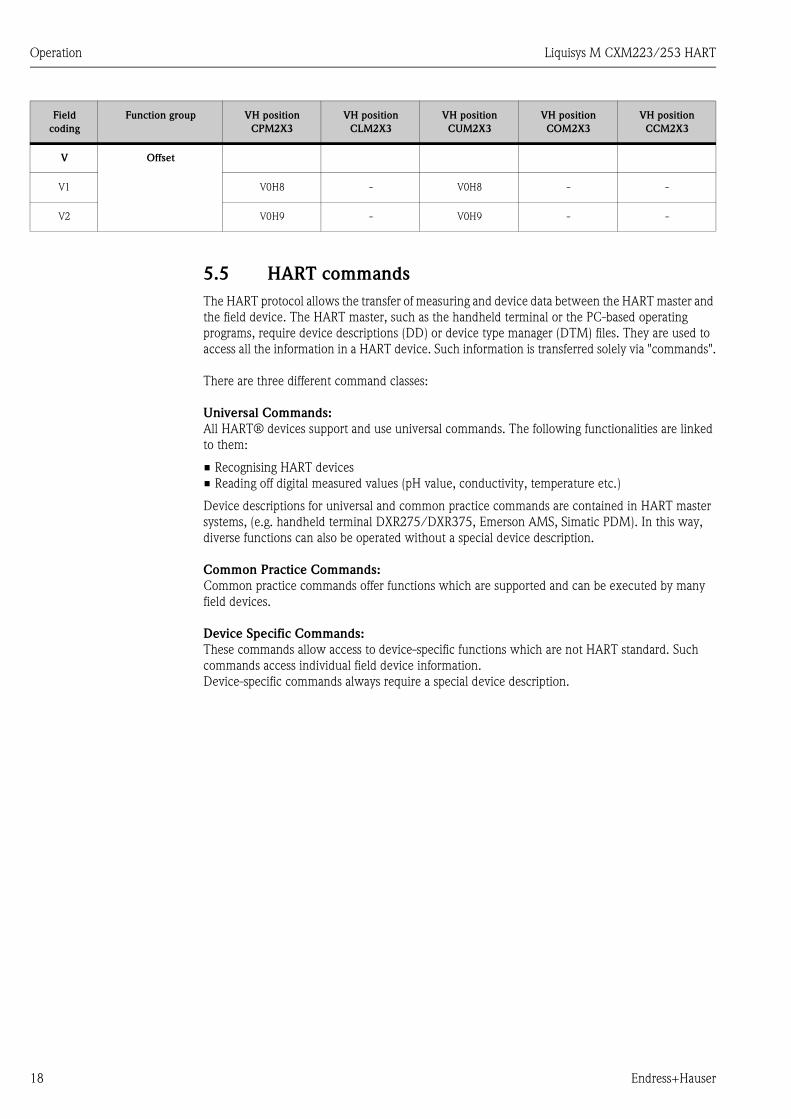
5.5 HART commands
The HART protocol allows the transfer of measuring and device data between the HART master and
the field device. The HART master, such as the handheld terminal or the PC-based operating
programs, require device descriptions (DD) or device type manager (DTM) files. They are used to
access all the information in a HART device. Such information is transferred solely via "commands".
There are three different command classes:
Universal Commands:
All HART® devices support and use universal commands. The following functionalities are linked
to them:
• Recognising HART devices
• Reading off digital measured values (pH value, conductivity, temperature etc.)
Device descriptions for universal and common practice commands are contained in HART master
systems, (e.g. handheld terminal DXR275/DXR375, Emerson AMS, Simatic PDM). In this way,
diverse functions can also be operated without a special device description.
Common Practice Commands:
Common practice commands offer functions which are supported and can be executed by many
field devices.
Device Specific Commands:
These commands allow access to device-specific functions which are not HART standard. Such
commands access individual field device information.
Device-specific commands always require a special device description.
V Offset
V1 V0H8 - V0H8 - -
V2 V0H9 - V0H9 - -
Field
coding
Function group VH position
CPM2X3
VH position
CLM2X3
VH position
CUM2X3
VH position
COM2X3
VH position
CCM2X3

Liquisys M CXM223/253 HART Operation
Endress+Hauser 19
The following table contains all the commands supported by Liquisys M CXM223/253.
Command No.
HART command / Access type
Command data
(numeric data in decimal form)
Response data
(numeric data in decimal form)
Universal Commands
0 Read unique device identifier
Access type = Read
none The device identifier provides information on the device
and manufacturer; it cannot be altered.
The response consists of a 12-byte device ID:
• Byte 0: fixed value 254
• Byte 1: manufacturer ID: 17 = E+H
• Byte 2: device type ID:
145 = CPM 2X3,
146 = CLM 2X3 inductive
147 = CLM 2X3 conductive
148 = COM 2X3
149 = CUM 2X3
150 = CCM 2X3
• Byte 3: number of preambles
• Byte 4: rev. no. universal commands
• Byte 5: rev. no. device-spec. commands
• Byte 6: software revision
• Byte 7: hardware revision
• Byte 8: additional device information
• Byte 9-11: device identification
1 Read main measured value
Access type = Read
none • Byte 0: HART unit ID of the main measured value
• Byte 1-4: main measured value
2 Read the main measured value as
current in mA and percentage of
the set mesauring range
Access type = Read
none • Byte 0-3: actual current of the current output 1 (main
measured value) in mA
• Byte 4-7: percentage of the set measuring range
3 Read the main measured value as
current in mA and four dynamic
process variables
Access type = Read
none 24 bytes are sent as a response
• Byte 0-3: current of the current output 1
(main measured value) in mA
• Byte 4: HART unit ID of the main measured value
• Byte 5-8: main measured value
• Byte 9: HART unit ID of the temperature
• Byte 10-13: temperature
6 Set HART short-form address
Access type = Write
Byte 0: desired address (0...15)
Factory setting: 0
With an address >0 (multi-drop mode) the current output
1 of the main measured value is fixed at 4 mA. Any
current simulation is terminated.
• Byte 0: active address
11 Read unique device identifier
using the tag
Access type = Read
Byte 0-5: tag
The tag can be set using command 18.
The device identifier provides information on the device
and manufacturer; it cannot be altered.
The response consists of a 12-byte device ID if the given
tag agrees with the one saved in the device:
• Byte 0: fixed value 254
• Byte 1: manufacturer ID: 17 = E+H
• Byte 2: device type ID:
• 145 = CPM 2X3,
146 = CLM 2X3 inductive
147 = CLM 2X3 conductive
148 = COM 2X3
149 = CUM 2X3
150 = CCM 2X3
• Byte 3: number of preambles
• Byte 4: rev. no. universal commands
• Byte 5: rev. no. device-spec. commands
• Byte 6: software revision
• Byte 7: hardware revision
• Byte 8: additional device information
• Byte 9-11: device identification
12 Read user message
Access type = Read
none • Byte 0-23: current user message
You can write the user message using command 17.

Operation Liquisys M CXM223/253 HART
20 Endress+Hauser
13 Read tag, tag description and date
Access type = Read
none • Byte 0-5: tag
• Byte 6-17: tag description
• Byte 18-20: date
You can write the tag, tag description and date using
command 18.
14 Read sensor information on the
main measured value
Access type = Read
none • Byte 0-2: serial number of the sensor
• Byte 3: HART unit ID of the sensor limits and
measuring range of the main measured value
• Byte 4-7: upper sensor limit
• Byte 8-11: lower sensor limit
• Byte 12-15: minimum distance between the limits
15 Read output information of main
measured value
Access type = Read
none • Byte 0: alarm selection ID
• Byte 1: ID for transfer function
• Byte 2: HART unit ID for the set measuring range of
the main measured value
• Byte 3-6: end of measuring range, value for 20 mA
• Byte 7-10: start of measuring range, value for 4 mA
• Byte 11-14: not used
• Byte 15: ID for write protection
• Byte 16: ID for OEM dealer: 17 = E+H
16 Read the device production
number
Access type = Read
none • Byte 0-2: production number
You can write the production number using command 19
17 Write user message
Access type = Write
You can save any 32-character long text in the device
with this parameter:
Byte 0-23: desired user message
• Byte 0-23: current user message
18 Write tag, tag description and date
Access type = Write
You can save an 8-character tag, a 16-character tag
description and a date with this parameter:
• Byte 0-5: tag
• Byte 6-17: tag description
• Byte 18-20: date
The "user tag" which can be set directly at transmitter
(menu field B6) is not identical to the tag for HART.
• Byte 0-5: tag
• Byte 6-17: tag description
• Byte 18-20: date
19 Write the device production
number
Access type = Write
You can save a production number in the range of
0 ... 1677715 with this parameter.
• Byte 0-2: production number
Common Practice Commands
34 Write attenuation constants for
main measured value
Access type = Write
• Byte 0-3: attenuation constants of the main measured
value in seconds
• Byte 0-3: attenuation constants in seconds
Dummy command: You can only write 0 s.
35 Write measuring range of main
measured value
Access type = Write
Write the desired measuring range:
• Byte 0: HART unit ID for the main measured value
• Byte 1-4: end of measuring range, value for 20 mA
• Byte 5-8: start of measuring range, value for 4 mA
• Byte 0: HART unit ID for the set measuring range of
the main measured value
• Byte 1-4: end of measuring range, value for 20 mA
• Byte 5-8: start of measuring range, value for 4 mA
38 Device status reset (Configuration
changed)
Access type = Write
none none
40 Simulate output current of main
measured value
Access type = Write
Simulation of the desired output current of the main
measured value. An entry value of 0 exits the simulation
mode:
• Byte 0-3: output current in mA
Values between 2 and 22 mA can be simulated. Current
simulation is not possible if the device is in multi-drop
mode.
• Byte 0-3: output current in mA
42 Perform device reset
Access type = Write
none
Communication is not possible during the device
initialisation which is necessary after a reset
(approx. 15 s).
none
Command No.
HART command / Access type
Command data
(numeric data in decimal form)
Response data
(numeric data in decimal form)

Liquisys M CXM223/253 HART Operation
Endress+Hauser 21
44 Write unit of the main measured
value
Access type = Write
Specify the unit of main measured value. Only units
which are suitable for the process variable are accepted by
the device:
• Byte 0: HART unit ID
The display unit of the instrument cannot really be
changed. This command exists for compatibility reasons.
Byte 0: HART unit ID
48 Read extended device status
Access type = Read
none none
59 Specify number of preambles in
message responses
Access type = Write
This parameter specifies the number of preambles which
are inserted in the message responses:
• Byte 0: number of preambles (5...20)
• Byte 0: number of preambles
108 Burst mode command
Write number
Access type = Write
The specified command is automatically executed in burst
mode
• Byte 0: number of command
• Byte 0: number of command
109 Burst mode control
Access type = Write
The burst mode can be controlled by the byte
transmitted.
• Byte 0: Burst control byte
0 = Off
1 = On
• Byte 0: Burst control byte
Device Specific Commands
142 Read display format
Access type = Read
Reads the number of places behind the decimal point of
the Commuwin II matrix position.
• Byte 0: VH position
lower 4 bits: H
upper 4 bits: V
• Byte 0: VH position
• Byte 1: places behind the decimal point
144 Read VH matrix variable
Access type = Read
Reads the Commuwin II variables with this command.
• Byte 0: VH position
lower 4 bits: H
upper 4 bits: V
• Byte 0: VH position
lower 4 bits: H
upper 4 bits: V
• Byte 1: HART unit ID
• Byte 2 ... n: VH variable
145 Write VH matrix variable
Access type = Write
Writes the Commuwin II variables with this command.
• Byte 0: VH position
lower 4 bits: H
upper 4 bits: V
• Byte 1: HART unit ID
• Byte 2 ... n: VH variable
• Byte 0: VH position
lower 4 bits: H
upper 4 bits: V
• Byte 1: HART unit ID
• Byte 2 ... n: VH variable
148 UPLOAD
Access type = Read
Reads EEPROM data from instrument connected.
• Byte 0 ... 3: segment number as ASCII code
• Byte 0 ... 3: segment number as ASCII code
• Byte 4 ... 24: max. 21 ASCII signs
149 DOWNLOAD
Access type = Write
Writes data into the EEPROM of the instrument
connected.
• Byte 0 ... 3: segment number as ASCII code
• Byte 4 ... 24: max. 21 ASCII signs
• Byte 0 ... 3: segment number as ASCIIcode
• Byte 4 ... 24: max. 21 ASCII signs
154 Read VH matrix variable with
2 byte unit
Access type = Read
Reads the Commuwin II variables with this command.
• Byte 0: VH position
lower 4 bits: H
upper 4 bits: V
• Byte 0: VH position
lower 4 bits: H
upper 4 bits: V
• Byte 1 ... 2: HART unit ID
• Byte 3 ... 4: VH variable
155 Write VH matrix variable with
2 byte unit
Access type = Write
Writes the Commuwin II variables with this command.
• Byte 0: VH position
lower 4 bits: H
upper 4 bits: V
• Byte 1 ... 2: HART unit ID
• Byte 3 ... 4: VH variable
• Byte 0: VH position
lower 4 bits: H
upper 4 bits: V
• Byte 1 ... 2: HART unit ID
• Byte 3 ... 4: VH variable
Command No.
HART command / Access type
Command data
(numeric data in decimal form)
Response data
(numeric data in decimal form)

Operation Liquisys M CXM223/253 HART
22 Endress+Hauser
Manufacturer-specific units for HART
Decimal Hexa-
decimal
Unit
CPM
Unit
CLM
Unit
CUM
Unit
COM
Unit
CCM
212 D4 - - - - µA
213 D5 - - - ppb ppb
240 F0 mV/pH S/m - mg/l mV/pH
241 F1 µA kΩ⋅cm - hPa -
242 F2 - MΩ⋅cm - % -
243 F3 - 1/cm - nA nA
244 F4 - - NTU - -
245 F5 - mg/l mg/l - -
246 F6 - S/cm FNU - -
247 F7 - µS/cm ppm - -
248 F8 - mS/cm hPa - -
249 F9 - kΩ⋅m % - -

Liquisys M CXM223/253 HART Commissioning
Endress+Hauser 23
6 Commissioning
6.1 Function check
# Warning!
• Check all connections for correctness.
• Make sure that the supply voltage is identical to the voltage written on the nameplate!
6.2 Setting of device address
All HART devices have the device address 0 on leaving the factory. This address can be changed to
connect up several devices for HART communication to the network, (multi-drop operation).
The device address can be set via
• local operation or
• handheld terminal DXR275/DXR375 or
• operating program Commuwin II or
• FieldCare
Setting the device address via the Liquisys M operating menu
Code Display Choice
(factory setting = bold)
Info User settings
I1 0
0 ... 15
Entry of the bus address
Each address may only be given once in a
network.
If a device address ≠ 0 is selected, the current
output is automatically set to 4 mA and the
device is set to multi-drop operation.
I2 Tag description
Here display only; cannot be edited.
0 I1
Address
@@@@@@@@
Tag I2

Maintenance Liquisys M CXM223/253 HART
24 Endress+Hauser
7 Maintenance
! Note!
Please refer to the standard Operating Instructions for information on maintenance of the measuring
point.
8 Accessories
• HART handheld terminal DXR375
– Handheld terminal for communicating with every HART-compatible device via a 4 ... 20 mA
line
Order no. DXR375
• HART modem Commubox FXA191
– Interface modul between HART interface and serial PC interface
– Technical Information TI237F/00/en
Order no. 016735-0000
• Commuwin II
– Graphic PC operating program for intelligent devices
– System Information SI003S/04/en
Order no. 556003946
• FieldCare
Tool für Plant-Asset-Management
Supports Ethernet, HART, PROFIBUS, FOUNDATION Fieldbus
FieldCare Lite, order no. 56004080
FieldCare Standard, order no. SFE551-xxxx
FieldCare Professional, order no. SFE552-xxxx
Liquisys M CXM223/253 HART Troubleshooting
Endress+Hauser 25
9 Troubleshooting
! Note!
For further information on trouble-shooting please refer to the standard Operating Instructions.
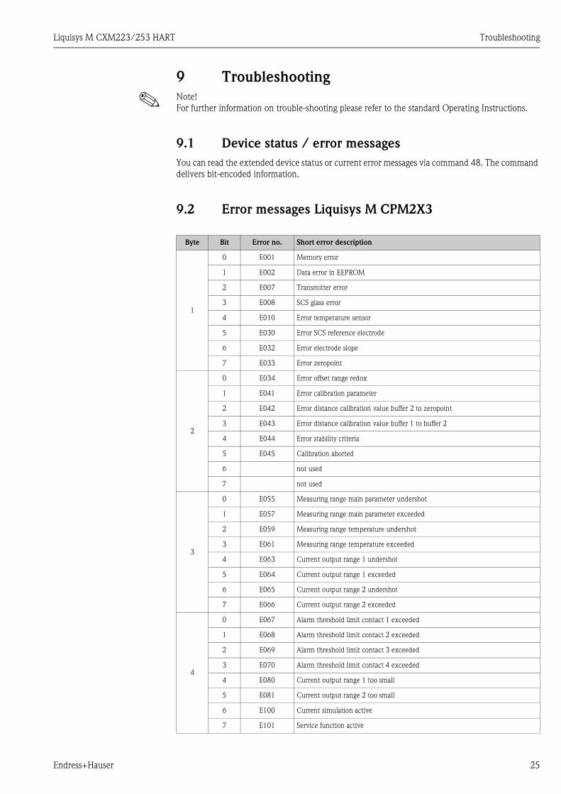
9.1 Device status / error messages
You can read the extended device status or current error messages via command 48. The command
delivers bit-encoded information.
9.2 Error messages Liquisys M CPM2X3
Byte Bit Error no. Short error description
1
0 E001 Memory error
1 E002 Data error in EEPROM
2 E007 Transmitter error
3 E008 SCS glass error
4 E010 Error temperature sensor
5 E030 Error SCS reference electrode
6 E032 Error electrode slope
7 E033 Error zeropoint
2
0 E034 Error offset range redox
1 E041 Error calibration parameter
2 E042 Error distance calibration value buffer 2 to zeropoint
3 E043 Error distance calibration value buffer 1 to buffer 2
4 E044 Error stability criteria
5 E045 Calibration aborted
6 not used
7 not used
3
0 E055 Measuring range main parameter undershot
1 E057 Measuring range main parameter exceeded
2 E059 Measuring range temperature undershot
3 E061 Measuring range temperature exceeded
4 E063 Current output range 1 undershot
5 E064 Current output range 1 exceeded
6 E065 Current output range 2 undershot
7 E066 Current output range 2 exceeded
4
0 E067 Alarm threshold limit contact 1 exceeded
1 E068 Alarm threshold limit contact 2 exceeded
2 E069 Alarm threshold limit contact 3 exceeded
3 E070 Alarm threshold limit contact 4 exceeded
4 E080 Current output range 1 too small
5 E081 Current output range 2 too small
6 E100 Current simulation active
7 E101 Service function active

Troubleshooting Liquisys M CXM223/253 HART
26 Endress+Hauser
9.3 Error messages Liquisys M CLM2X3
Byte Bit Error no. Short error description
1
0 E001 Memory error
1 E002 Data error in EEPROM
2 E007 Transmitter error
3 E008 Sensor error
4 E010 Error temperature sensor
5 E025 Airset value exceeded
6 E036 Cell constant exceeded
7 E037 Cell constant undershot
2
0 E045 Calibration aborted
1 not used
2 not used
3 E049 Installation factor exceeded
4 E050 Installation factor undershot
5 E055 Measuring range main parameter undershot
6 E057 Measuring range main parameter exceeded
7 E059 Measuring range temperature undershot
3
0 E061 Measuring range temperature exceeded
1 E063 Current output range 1 undershot
2 E064 Current output range 1 exceeded
3 E065 Current output range 2 undershot
4 E066 Current output range 2 exceeded
5 E067 Alarm threshold limit contact 1 exceeded
6 E068 Alarm threshold limit contact 2 exceeded
7 E069 Alarm threshold limit contact 3 exceeded
4
0 E070 Alarm threshold limit contact 4 exceeded
1 E071 Polarisation error
2 E072 Temperature exceeds Éα-value range
3 E078 Temperature exceeds concentration table
4 E079 Conductivity exceeds concentration table
5 E080 Current output range 1 too small
6 E081 Current output range 2 too small
7 E100 Current simulation active

Liquisys M CXM223/253 HART Troubleshooting
Endress+Hauser 27
9.4 Error messages Liquisys M COM2X3
Byte Bit Error no. Short error description
1
0 E001 Memory error
1 E002 Data error in EEPROM
2 E007 Transmitter error
3 E032 Error sensor slope
4 E044 Error signal stability
5 E057 Measuring range main parameter exceeded
6 E058 Measuring range temperature undershot
7 E059 Measuring range temperature exceeded
2
0 E063 Current output range 1 undershot
1 E064 Current output range 1 exceeded
2 E065 Current output range 2 undershot
3 E066 Current output range 2 exceeded
4 E067 Alarm threshold limit contact 1 exceeded
5 E068 Alarm threshold limit contact 2 exceeded
6 E069 Alarm threshold limit contact 3 exceeded
7 E070 Alarm threshold limit contact 4 exceeded
3
0 E080 Current output range 1 too small
1 E081 Current output range 2 too small
2 E082 Air pressure range undershot
3 E083 Air pressure range exceeded
4 E100 Current simulation active
5 E101 Service function active
6 E102 Manual mode active
7 E106 Download active
4
0 E116 Download error
1 not used
2 not used
3 E018 Diaphragm error
4 E020 Sensor signal range undershot
5 E022 Sensor signal range exceeded
6 E003 Invalid configuration
7 E004 Incompatible hardware or software

Troubleshooting Liquisys M CXM223/253 HART
28 Endress+Hauser
9.5 Error messages Liquisys M CUM2X3
Byte Bit Error no. Short error description
1
0 E001 Memory error
1 E002 Data error in EEPROM
2 E007 Transmitter error
3 E008 Sensor error
4 E010 Error temperature sensor
5 not used
6 E026 Wiper error
7 E032 Error sensor slope
2
0 not used
1 not used
2 E044 Error stability criteria
3 E045 Calibration aborted
4 not used
5 not used
6 not used
7 not used
3
0 E055 Measuring range main parameter undershot
1 E057 Measuring range main parameter exceeded
2 E059 Measuring range temperature undershot
3 E061 Measuring range temperature exceeded
4 E063 Current output range 1 undershot
5 E064 Current output range 1 exceeded
6 E065 Current output range 2 undershot
7 E066 Current output range 2 exceeded
4
0 E067 Alarm threshold limit contact 1 exceeded
1 E068 Alarm threshold limit contact 2 exceeded
2 E069 Alarm threshold limit contact 3 exceeded
3 E070 Alarm threshold limit contact 4 exceeded
4 not used
5 not used
6 not used
7 not used

Liquisys M CXM223/253 HART Troubleshooting
Endress+Hauser 29
9.6 Error messages Liquisys M CCM2X3
Byte Bit Error no. Short error description
1
0 E001 Memory error
1 E002 Data error in EEPROM
2 E007 Transmitter error
3 E032 Error sensor slope pH
4 E038 Error sensor slope Cl
5 E033 Error zeropoint
6 E034 Error offset range redox
7 E035 Error offset range sensor 963
2
0 E042 Error distance calibration value buffer 2 to zeropoint
1 E043 Error distance calibration value buffer 1 to buffer 2
2 E044 Error stability criteria
3 E045 Calibration aborted
4 E046 Limits current output 1 exchanged
5 E047 Limits current output 2 exchanged
6 E055 Measuring range main parameter (Cl) undershot
7 E057 Measuring range main parameter (Cl) exceeded
3
0 E056 Measuring range second parameter (pH) undershot
1 E058 Measuring range second parameter (pH) exceeded
2 E059 Measuring range temperature undershot
3 E061 Measuring range temperature exceeded
4 E063 Current output range 1 undershot
5 E064 Current output range 1 exceeded
6 E065 Current output range 2 undershot
7 E066 Current output range 2 exceeded
4
0 E067 Alarm threshold limit contact 1 exceeded
1 E068 Alarm threshold limit contact 2 exceeded
2 E069 Alarm threshold limit contact 3 exceeded
3 E070 Alarm threshold limit contact 4 exceeded
4 E080 Current output range 1 too small
5 E081 Current output range 2 too small
6 E100 Current simulation active
7 E101 Service function active

Technical data Liquisys M CXM223/253 HART
30 Endress+Hauser
10 Technical data
10.1 Output
10.2 Power supply
10.3 Display and user interface
Output signal pH, redox, conductivity, turbidity, oxygen, chlorine, temperature
(depending on device version)
Current output I Current range 4 ... 20 mA
Power supply depending on device version:
100/115/230 V AC +10/-15 %, 48 ... 62 Hz
24 V AC/DC +20/-15 %
Power consumption max. 7.5 VA
Main fuse Micro-fuse, medium-lag 250 V/3.15 A
On-site operation via HART handheld terminal DXR375
PC operation via HART modem Commubox FXA191 with
operating program Commuwin II or
FieldCare
Device address can be set, 0 ... 15

Liquisys M CXM223/253 HART
Endress+Hauser 31
Index
AAccessories . . . . . . . . . . . . . . . . . . . . . . . . . . . . . . . . . . . . 24
Address. . . . . . . . . . . . . . . . . . . . . . . . . . . . . . . . . . . . . . . 23
Approvals . . . . . . . . . . . . . . . . . . . . . . . . . . . . . . . . . . . . . . 6
CCertificate . . . . . . . . . . . . . . . . . . . . . . . . . . . . . . . . . . . . . . 6
Commands . . . . . . . . . . . . . . . . . . . . . . . . . . . . . . . . . . . . 18
Commissioning . . . . . . . . . . . . . . . . . . . . . . . . . . . . . . . . . . 4
Commuwin II . . . . . . . . . . . . . . . . . . . . . . . . . . . . . . . . . . 12
Connection . . . . . . . . . . . . . . . . . . . . . . . . . . . . . . . . . . . . . 8
DDeclaration of conformity . . . . . . . . . . . . . . . . . . . . . . . . . . 6
Designated use . . . . . . . . . . . . . . . . . . . . . . . . . . . . . . . . . . 4
Device address . . . . . . . . . . . . . . . . . . . . . . . . . . . . . . . . . 23
Device status. . . . . . . . . . . . . . . . . . . . . . . . . . . . . . . . . . . 25
Display . . . . . . . . . . . . . . . . . . . . . . . . . . . . . . . . . . . . . . . 11
DXR375
Connection . . . . . . . . . . . . . . . . . . . . . . . . . . . . . . . . . . 9
EElectrical icons . . . . . . . . . . . . . . . . . . . . . . . . . . . . . . . . . . 5
Error messages . . . . . . . . . . . . . . . . . . . . . . . . . . . . . . . . . 25
CCM2X3. . . . . . . . . . . . . . . . . . . . . . . . . . . . . . . . . . . 29
CLM2X3 . . . . . . . . . . . . . . . . . . . . . . . . . . . . . . . . . . . 26
COM2X3 . . . . . . . . . . . . . . . . . . . . . . . . . . . . . . . . . . 27
CPM2X3 . . . . . . . . . . . . . . . . . . . . . . . . . . . . . . . . . . . 25
CUM2X3. . . . . . . . . . . . . . . . . . . . . . . . . . . . . . . . . . . 28
FFieldCare . . . . . . . . . . . . . . . . . . . . . . . . . . . . . . . . . . . . . 12
Function check . . . . . . . . . . . . . . . . . . . . . . . . . . . . . . . . . 23
HHandheld terminal . . . . . . . . . . . . . . . . . . . . . . . . . . . . . . . 9
HART commands . . . . . . . . . . . . . . . . . . . . . . . . . . . . . . . 18
IIcons
Electrical . . . . . . . . . . . . . . . . . . . . . . . . . . . . . . . . . . . . 5
Immunity to interference. . . . . . . . . . . . . . . . . . . . . . . . . . . 4
Installation . . . . . . . . . . . . . . . . . . . . . . . . . . . . . . . . . . . . . 4
MMaintenance . . . . . . . . . . . . . . . . . . . . . . . . . . . . . . . . . . . 24
NNameplate . . . . . . . . . . . . . . . . . . . . . . . . . . . . . . . . . . . . . 6
OOperation . . . . . . . . . . . . . . . . . . . . . . . . . . . . . . . . . . . 4, 11
Commuwin II . . . . . . . . . . . . . . . . . . . . . . . . . . . . . . . 12
DXR375 . . . . . . . . . . . . . . . . . . . . . . . . . . . . . . . . . . . 11
FieldCare. . . . . . . . . . . . . . . . . . . . . . . . . . . . . . . . . . . 12
Operational safety . . . . . . . . . . . . . . . . . . . . . . . . . . . . . . . . 4
Output . . . . . . . . . . . . . . . . . . . . . . . . . . . . . . . . . . . . . . . 30
PPost-connection check. . . . . . . . . . . . . . . . . . . . . . . . . . . . 10
Post-installation check . . . . . . . . . . . . . . . . . . . . . . . . . . . . . 7
Power supply. . . . . . . . . . . . . . . . . . . . . . . . . . . . . . . . . . . 30
SSafety instructions . . . . . . . . . . . . . . . . . . . . . . . . . . . . . . . . 4
Scope of delivery . . . . . . . . . . . . . . . . . . . . . . . . . . . . . . . . . 6
Set device address . . . . . . . . . . . . . . . . . . . . . . . . . . . . . . . 23
System equipment . . . . . . . . . . . . . . . . . . . . . . . . . . . . . . . . 7
TTroubleshooting . . . . . . . . . . . . . . . . . . . . . . . . . . . . . . . . 25

www.endress.com/worldwide
BA208C/07/en/10.05
51517596
Printed in Germany / FM+SGML 6.0 / DT51517596