operating instructions finn-power - pulsar ®...
TRANSCRIPT
OPERATINGINSTRUCTIONS
FINN-POWERP20 MS �
P20 IS/AS �
P20 VS �
P21 MS �
P21 IS/AS �
P21 VS �
P32 MS �
P32 IS/AS �
P32 VS �
P51 IS/AS �
P51 VS �
CC22 IS/AS �
CC22 VS �
MANUFACTURING YEAR ____________
RELEASED 06/00
KEEP THIS MANUAL FOR FUTURE NEEDS
THE MACHINE HAS BEEN DESIGNED FOR CRIMPING HOSE FITTINGS.LILLBACKA POWERCO SHALL NOT BE HELD LIABLE FOR ANYPRODUCT WHICH HAS BEEN CRIMPED ON THE MACHINE. THEMACHINE HAS BEEN DESIGNED TO OPERATE IN ROOMTEMPERATURE, IN DRY INDOOR CONDITIONS AND IN SUFFICIENTILLUMINATION. USING THE MACHINE FOR ANY OTHER PURPOSE ISNOT ALLOWED WITHOUT WRITTEN CONSENT FROM THE FACTORY.
Lillbacka Powerco OyP.O.B. 1FIN-62301 Härmä, Finlandtel. + 358 6 485 4444fax + 358 6 485 4400
CONTENTSCONTENTS ...........................................................................................................................2
GENERAL .............................................................................................................................3TRANSPORT ......................................................................................................................................................3STORAGE...........................................................................................................................................................3MOUNTING .........................................................................................................................................................3
WARNINGS ...........................................................................................................................4GENERAL ...........................................................................................................................................................4DANGER ZONES................................................................................................................................................4
COMMISSIONING .................................................................................................................5OIL FILL ..............................................................................................................................................................5ELECTRICAL CONNECTION .............................................................................................................................5QUICK FIX-PACKAGE ........................................................................................................................................5
OPERATION..........................................................................................................................6CONTROL IDENTIFICATION MS -CONTROL..................................................................................................6CONTROL IDENTIFICATION IS/AS/VS -CONTROLS......................................................................................6CONTROL PANEL IS/AS ..................................................................................................................................7CONTROL PANEL VS.......................................................................................................................................9COVERS P32 ...................................................................................................................................................11TEST RUN MS/IS/AS CONTROLS ................................................................................................................11TEST RUN VS CONTROL .............................................................................................................................11SELECTING THE DIE SET P20, P21 ...........................................................................................................12SELECTING THE DIE SET CC22 ..................................................................................................................12SELECTING THE DIE SET P32....................................................................................................................13SELECTING THE DIE SET P51....................................................................................................................13
FP140 DIE SETS FOR P51 -MODEL .......................................................................................................14INSTALLING THE DIE SET............................................................................................................................14
QUICK CHANGE MS/IS/AS........................................................................................................................14QUICK CHANGE VS ..................................................................................................................................15CHANGE OF A SINGLE DIE P20, P21, P32, CC22................................................................................15CHANGE OF A SINGLE DIE P51............................................................................................................15
SETTING THE CRIMPING DIAMETER MS...................................................................................................16SETTING THE CRIMPING DIAMETER IS/AS...............................................................................................17SETTING THE CRIMPING DIAMETER VS ...................................................................................................18OPERATION LIMITATIONS P51, CC22..........................................................................................................18CRIMPING MS -CONTROL..............................................................................................................................18CRIMPING IS/AS/VS -CONTROLS.................................................................................................................19ADJUSTMENT OF RETRACTION DIAMETER IS/AS ...................................................................................20IF THE MACHINE DOES NOT WORK... ......................................................................................................21
PREVENTIVE MAINTENANCE...........................................................................................21GREASING P20, P21, P32 ..............................................................................................................................21GREASING P51 ...............................................................................................................................................21GREASING CC22 ............................................................................................................................................22OIL CHANGE ...................................................................................................................................................22FILTER CHANGE P20, P21, P32, CC22...........................................................................................................22FILTER CHANGE P51 ....................................................................................................................................23PRESSURE PIPES ...........................................................................................................................................23FINAL DECELERATION P51 ..........................................................................................................................23RE-CALIBRATION OF CRIMPING DIAMETER DIAL MS -CONTROL.........................................................23
TROUBLESHOOTING.........................................................................................................24
GUARANTEE.......................................................................................................................24
TECHNICAL DATA.............................................................................................................25TECHNICAL DATA P20 ..................................................................................................................................25TECHNICAL DATA P21 ..................................................................................................................................27TECHNICAL DATA P32 ..................................................................................................................................29TECHNICAL DATA P51 ..................................................................................................................................30TECHNICAL DATA CC22.....................................................................................................................32
GENERALFINN-POWER crimping machines are electrically operated hydraulic crimping machines for hydraulic hoseassemblies.The crimping machine comprises a crimping head and a hydraulic unit mounted on the oil tank which servesas machine frame.FINN-POWER crimping machine is normally delivered with a 3-phase electric motor. On request it can beequipped with a single phase motor.
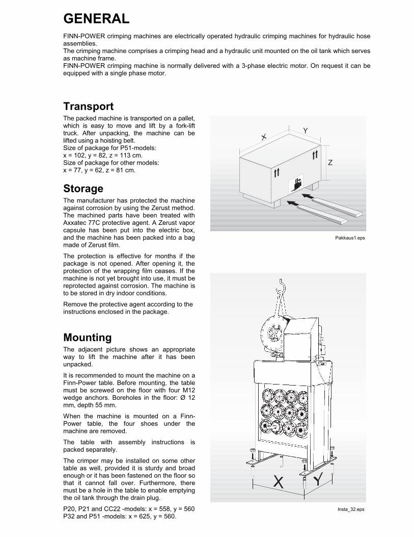
TransportThe packed machine is transported on a pallet,which is easy to move and lift by a fork-lifttruck. After unpacking, the machine can belifted using a hoisting belt.Size of package for P51-models:x = 102, y = 82, z = 113 cm.Size of package for other models:x = 77, y = 62, z = 81 cm.
StorageThe manufacturer has protected the machineagainst corrosion by using the Zerust method.The machined parts have been treated withAxxatec 77C protective agent. A Zerust vaporcapsule has been put into the electric box,and the machine has been packed into a bagmade of Zerust film.
The protection is effective for months if thepackage is not opened. After opening it, theprotection of the wrapping film ceases. If themachine is not yet brought into use, it must bereprotected against corrosion. The machine isto be stored in dry indoor conditions.
Remove the protective agent according to theinstructions enclosed in the package.
MountingThe adjacent picture shows an appropriateway to lift the machine after it has beenunpacked.
It is recommended to mount the machine on aFinn-Power table. Before mounting, the tablemust be screwed on the floor with four M12wedge anchors. Boreholes in the floor: Ø 12mm, depth 55 mm.
When the machine is mounted on a Finn-Power table, the four shoes under themachine are removed.
The table with assembly instructions ispacked separately.
The crimper may be installed on some othertable as well, provided it is sturdy and broadenough or it has been fastened on the floor sothat it cannot fall over. Furthermore, theremust be a hole in the table to enable emptyingthe oil tank through the drain plug.
P20, P21 and CC22 -models: x = 558, y = 560P32 and P51 -models: x = 625, y = 560.
Insta_32.eps
Pakkaus1.eps
4
WARNINGSGeneralThe machine is intended for professional use. It is to be operated only by a trained operator who hasunderstood the dangers involved in the operation.
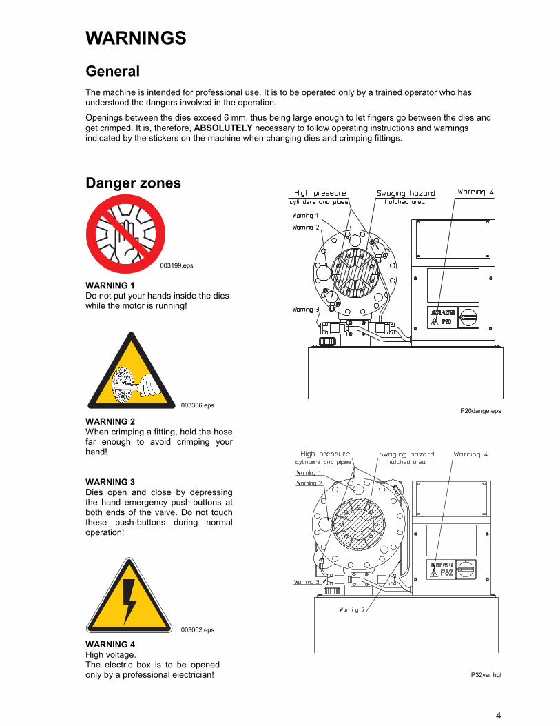
Openings between the dies exceed 6 mm, thus being large enough to let fingers go between the dies andget crimped. It is, therefore, ABSOLUTELY necessary to follow operating instructions and warningsindicated by the stickers on the machine when changing dies and crimping fittings.
Danger zones
WARNING 1Do not put your hands inside the dieswhile the motor is running!
WARNING 2When crimping a fitting, hold the hosefar enough to avoid crimping yourhand!
WARNING 3Dies open and close by depressingthe hand emergency push-buttons atboth ends of the valve. Do not touchthese push-buttons during normaloperation!
WARNING 4High voltage.The electric box is to be openedonly by a professional electrician!
003002.eps
003306.eps
003199.eps
P20dange.eps
P32var.hgl
5
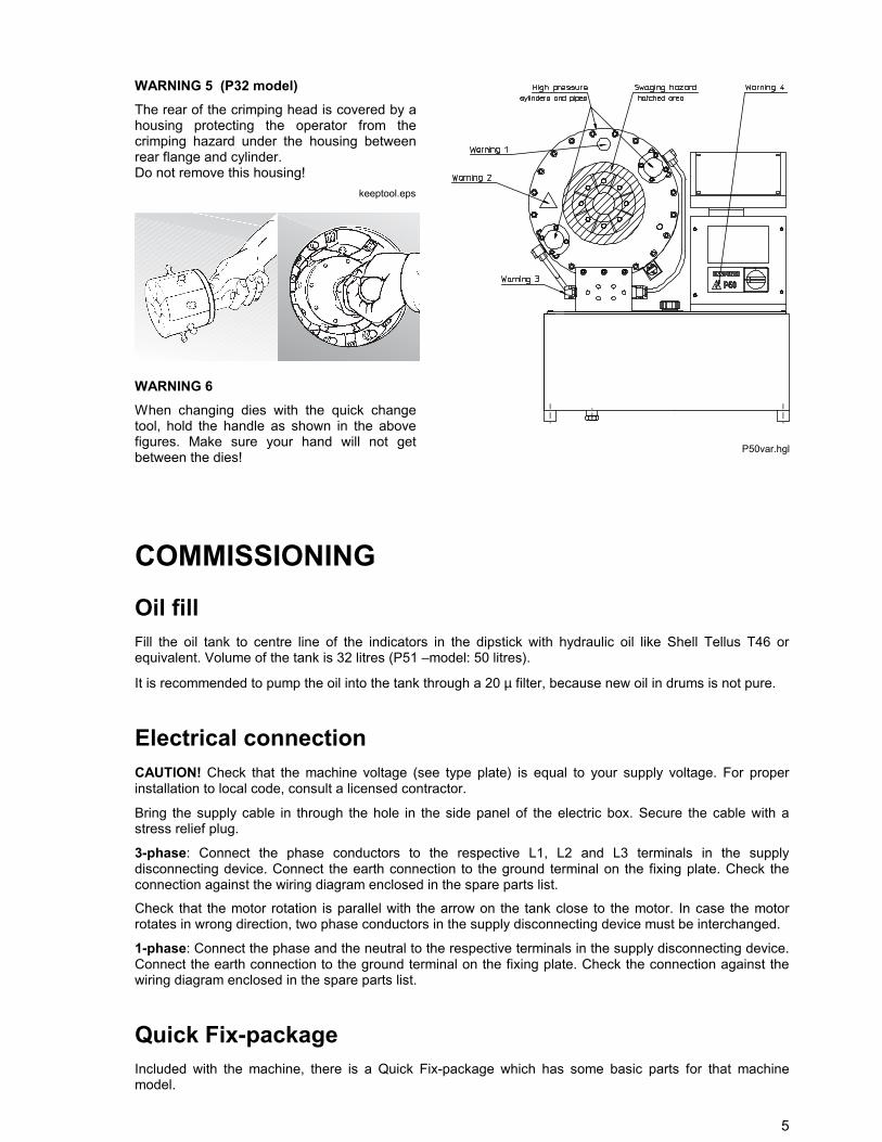
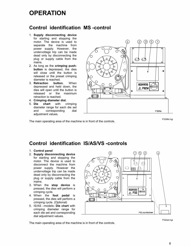
WARNING 5 (P32 model)The rear of the crimping head is covered by ahousing protecting the operator from thecrimping hazard under the housing betweenrear flange and cylinder.Do not remove this housing!
WARNING 6When changing dies with the quick changetool, hold the handle as shown in the abovefigures. Make sure your hand will not getbetween the dies!
COMMISSIONINGOil fillFill the oil tank to centre line of the indicators in the dipstick with hydraulic oil like Shell Tellus T46 orequivalent. Volume of the tank is 32 litres (P51 –model: 50 litres).
It is recommended to pump the oil into the tank through a 20 µ filter, because new oil in drums is not pure.
Electrical connectionCAUTION! Check that the machine voltage (see type plate) is equal to your supply voltage. For properinstallation to local code, consult a licensed contractor.
Bring the supply cable in through the hole in the side panel of the electric box. Secure the cable with astress relief plug.
3-phase: Connect the phase conductors to the respective L1, L2 and L3 terminals in the supplydisconnecting device. Connect the earth connection to the ground terminal on the fixing plate. Check theconnection against the wiring diagram enclosed in the spare parts list.
Check that the motor rotation is parallel with the arrow on the tank close to the motor. In case the motorrotates in wrong direction, two phase conductors in the supply disconnecting device must be interchanged.
1-phase: Connect the phase and the neutral to the respective terminals in the supply disconnecting device.Connect the earth connection to the ground terminal on the fixing plate. Check the connection against thewiring diagram enclosed in the spare parts list.
Quick Fix-packageIncluded with the machine, there is a Quick Fix-package which has some basic parts for that machinemodel.
keeptool.eps
P50var.hgl
6
OPERATION
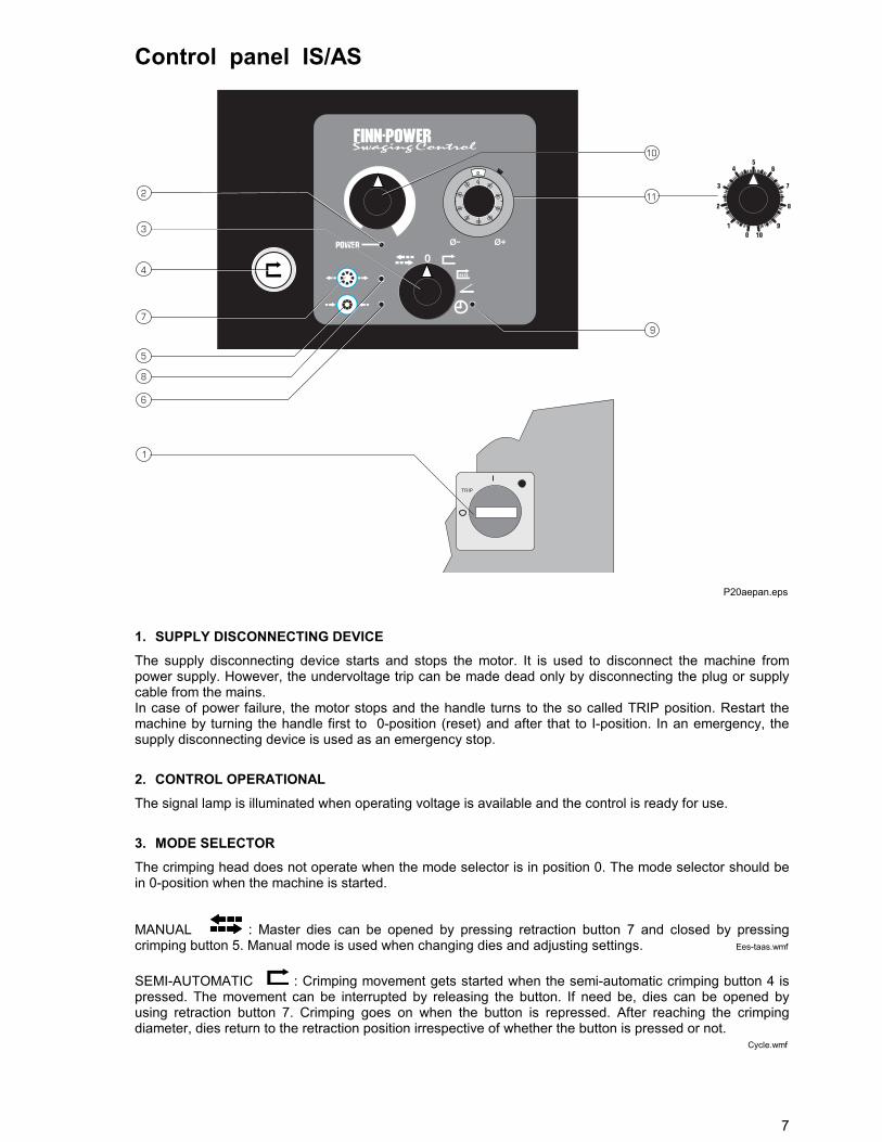
Control identification MS -control1. Supply disconnecting device
for starting and stopping themotor. The device is used toseparate the machine frompower supply. However, theundervoltage trip can be madedead only by disconnecting theplug or supply cable from themains.
2. As long as the crimping push-button is depressed, the dieswill close until the button isreleased or the preset crimpingdiameter is reached.
3. Retraction button. Whendepressed and held down, thedies will open until the button isreleased or the maximumretraction is reached.
4. Crimping diameter dial.5. Die chart with crimping
diameter range for each die setand corresponding dialadjustment values.
The main operating area of the machine is in front of the controls.
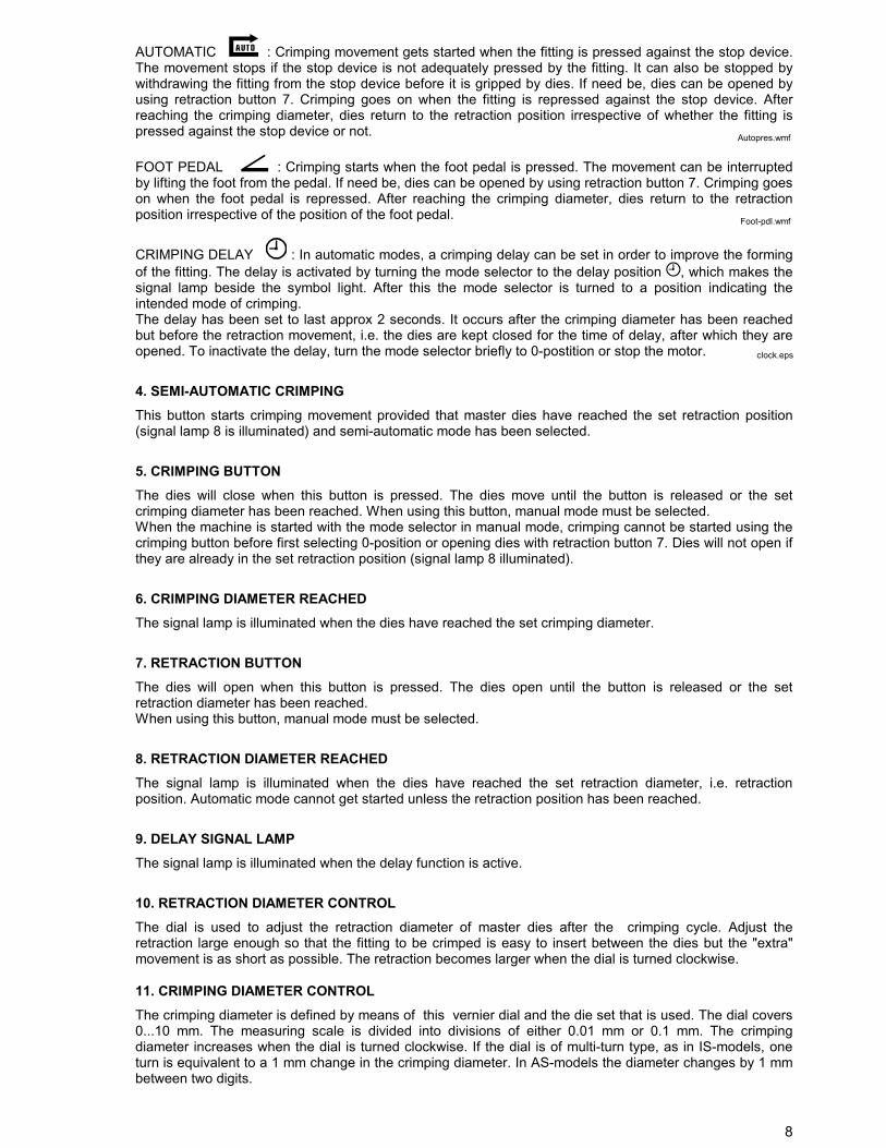
Control identification IS/AS/VS -controls1. Control panel2. Supply disconnecting device
for starting and stopping themotor. The device is used todisconnect the machine frompower supply. However theundervoltage trip can be madedead only by disconnecting theplug or supply cable from themains.
3. When the stop device ispressed, the dies will perform acrimping cycle.
4. When the foot pedal ispressed, the dies will perform acrimping cycle. (Optional)
5. IS/AS –models: Die chart withcrimping diameter range foreach die set and correspondingdial adjustment values.
The main operating area of the machine is in front of the controls.P32iskl.hgl
P32Mkl.hgl
7
Control panel IS/AS
0
0
0
50
90
40
80
30
70
20
60
10
TRIP
1. SUPPLY DISCONNECTING DEVICEThe supply disconnecting device starts and stops the motor. It is used to disconnect the machine frompower supply. However, the undervoltage trip can be made dead only by disconnecting the plug or supplycable from the mains.In case of power failure, the motor stops and the handle turns to the so called TRIP position. Restart themachine by turning the handle first to 0-position (reset) and after that to I-position. In an emergency, thesupply disconnecting device is used as an emergency stop.
2. CONTROL OPERATIONALThe signal lamp is illuminated when operating voltage is available and the control is ready for use.
3. MODE SELECTORThe crimping head does not operate when the mode selector is in position 0. The mode selector should bein 0-position when the machine is started.
MANUAL : Master dies can be opened by pressing retraction button 7 and closed by pressingcrimping button 5. Manual mode is used when changing dies and adjusting settings.
SEMI-AUTOMATIC : Crimping movement gets started when the semi-automatic crimping button 4 ispressed. The movement can be interrupted by releasing the button. If need be, dies can be opened byusing retraction button 7. Crimping goes on when the button is repressed. After reaching the crimpingdiameter, dies return to the retraction position irrespective of whether the button is pressed or not.
P20aepan.eps
Ees-taas.wmf
Cycle.wmf
8
AUTOMATIC : Crimping movement gets started when the fitting is pressed against the stop device.The movement stops if the stop device is not adequately pressed by the fitting. It can also be stopped bywithdrawing the fitting from the stop device before it is gripped by dies. If need be, dies can be opened byusing retraction button 7. Crimping goes on when the fitting is repressed against the stop device. Afterreaching the crimping diameter, dies return to the retraction position irrespective of whether the fitting ispressed against the stop device or not.
FOOT PEDAL : Crimping starts when the foot pedal is pressed. The movement can be interruptedby lifting the foot from the pedal. If need be, dies can be opened by using retraction button 7. Crimping goeson when the foot pedal is repressed. After reaching the crimping diameter, dies return to the retractionposition irrespective of the position of the foot pedal.
CRIMPING DELAY : In automatic modes, a crimping delay can be set in order to improve the formingof the fitting. The delay is activated by turning the mode selector to the delay position , which makes thesignal lamp beside the symbol light. After this the mode selector is turned to a position indicating theintended mode of crimping.The delay has been set to last approx 2 seconds. It occurs after the crimping diameter has been reachedbut before the retraction movement, i.e. the dies are kept closed for the time of delay, after which they areopened. To inactivate the delay, turn the mode selector briefly to 0-postition or stop the motor.
4. SEMI-AUTOMATIC CRIMPINGThis button starts crimping movement provided that master dies have reached the set retraction position(signal lamp 8 is illuminated) and semi-automatic mode has been selected.
5. CRIMPING BUTTONThe dies will close when this button is pressed. The dies move until the button is released or the setcrimping diameter has been reached. When using this button, manual mode must be selected.When the machine is started with the mode selector in manual mode, crimping cannot be started using thecrimping button before first selecting 0-position or opening dies with retraction button 7. Dies will not open ifthey are already in the set retraction position (signal lamp 8 illuminated).
6. CRIMPING DIAMETER REACHEDThe signal lamp is illuminated when the dies have reached the set crimping diameter.
7. RETRACTION BUTTONThe dies will open when this button is pressed. The dies open until the button is released or the setretraction diameter has been reached.When using this button, manual mode must be selected.
8. RETRACTION DIAMETER REACHEDThe signal lamp is illuminated when the dies have reached the set retraction diameter, i.e. retractionposition. Automatic mode cannot get started unless the retraction position has been reached.
9. DELAY SIGNAL LAMPThe signal lamp is illuminated when the delay function is active.
10. RETRACTION DIAMETER CONTROLThe dial is used to adjust the retraction diameter of master dies after the crimping cycle. Adjust theretraction large enough so that the fitting to be crimped is easy to insert between the dies but the "extra"movement is as short as possible. The retraction becomes larger when the dial is turned clockwise.
11. CRIMPING DIAMETER CONTROLThe crimping diameter is defined by means of this vernier dial and the die set that is used. The dial covers0...10 mm. The measuring scale is divided into divisions of either 0.01 mm or 0.1 mm. The crimpingdiameter increases when the dial is turned clockwise. If the dial is of multi-turn type, as in IS-models, oneturn is equivalent to a 1 mm change in the crimping diameter. In AS-models the diameter changes by 1 mmbetween two digits.
Foot-pdl.wmf
Autopres.wmf
clock.eps
9
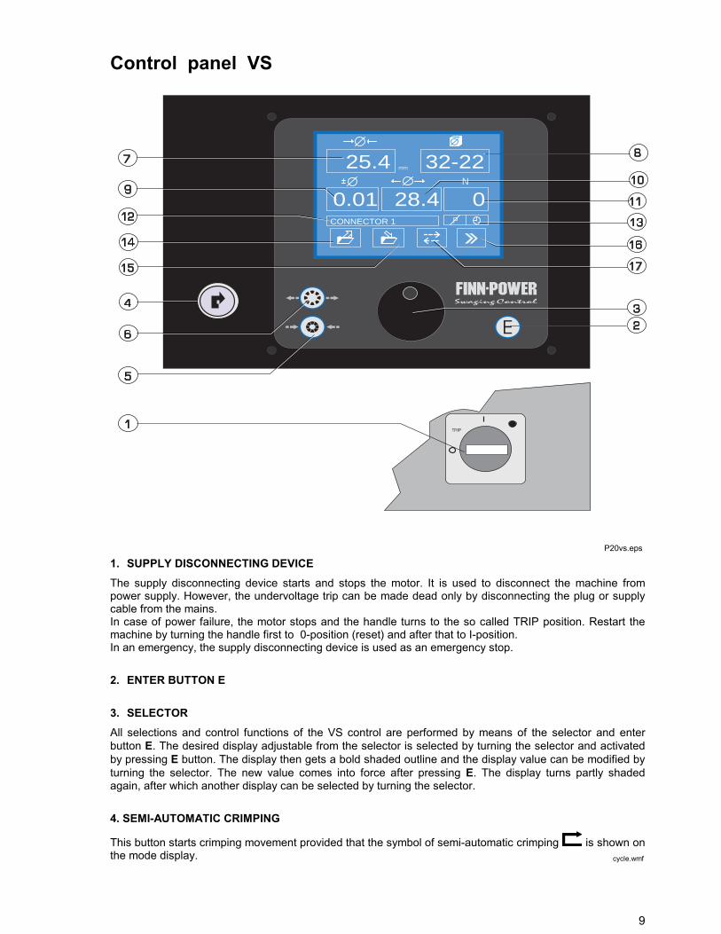
Control panel VS
25.4
28.4 00.01
32-22
CONNECTOR 1
1. SUPPLY DISCONNECTING DEVICEThe supply disconnecting device starts and stops the motor. It is used to disconnect the machine frompower supply. However, the undervoltage trip can be made dead only by disconnecting the plug or supplycable from the mains.In case of power failure, the motor stops and the handle turns to the so called TRIP position. Restart themachine by turning the handle first to 0-position (reset) and after that to I-position.In an emergency, the supply disconnecting device is used as an emergency stop.
2. ENTER BUTTON E 3. SELECTORAll selections and control functions of the VS control are performed by means of the selector and enterbutton E. The desired display adjustable from the selector is selected by turning the selector and activatedby pressing E button. The display then gets a bold shaded outline and the display value can be modified byturning the selector. The new value comes into force after pressing E. The display turns partly shadedagain, after which another display can be selected by turning the selector.
4. SEMI-AUTOMATIC CRIMPING
This button starts crimping movement provided that the symbol of semi-automatic crimping is shown onthe mode display.
P20vs.eps
cycle.wmf

10
5. CRIMPING BUTTONThe dies will close when this button is pressed. The dies move until the button is released or the setcrimping diameter has been reached.When using this button, manual mode must be selected.
6. RETRACTION BUTTONThe dies will open when this button is pressed. The dies open until the button is released or the setretraction diameter has been reached.This button can be used either in manual mode or in semi-automatic and foot pedal modes in a situationwhen you want to open dies in the middle of crimping.
7. CRIMPING DIAMETERThe crimping diameter is defined by selecting a value on this display and by means of the die set that is used.The crimping range extends from the minimum crimping diameter of the smallest die set programmed up tothe maximum crimping diameter of the largest die set programmed. It is divided into divisions of 0.1 mm. Inaddition, the crimping diameter can be modified by correction adjustment.
8. DIE SETWhen the crimping diameter is being adjusted, VS control automatically recommends a die set best suitedfor the selected diameter. If desired, the operator may use another die set covering the diameter inquestion. Thus he may manage to avoid changing die sets but the crimping result will not be as good as ifthe recommended die set would have been used.
9. CORRECTIONDifferent fittings require more or less crimping force. The machine frame design, however contracts andexpands according to the required crimping force. That is why the crimping diameter must be corrected inorder to reach the intended crimping result. It is recommended to use the correction function in modifyingthe crimping diameter so that the correct crimping diameter for the fitting in question could be saved on thecrimping diameter display for the next time it is needed.
10. RETRACTION DIAMETERThe retraction diameter indicates the opening of master dies after the crimping cycle. Adjust the retractionlarge enough so that the fitting to be crimped is easy to insert between the dies but the ”extra” movement isas short as possible. The retraction value is the diameter of the opening between the dies in millimetres.
11. CRIMP COUNTERThe counter counts crimps either from zero or from a set value onwards.
12. FITTING TYPECrimping data of your own or of the fitting manufacturer can be stored in the memory of the control unit. Youcan name a fitting type as you like or use fitting types of the fitting manufacturer.
13. PRESSURE SWITCH AND CRIMPING DELAYPressure switch function and crimping delay on/off. See VS control, page 9.
14. RECALL OF STORED CRIMPING DATAThe crimping data of a certain fitting type can be recalled from the control unit memory. See VS control, page6.
15. STORING OF CRIMPING DATACrimping data are stored in the memory for the next time to be used. It is worth while naming a fitting type tofacilitate finding it again. See VS control, page 8.
16. SETUPSSet-ups of crimping delay, pressure switch, mm/inch and calibration. See VS control, page 10.
11
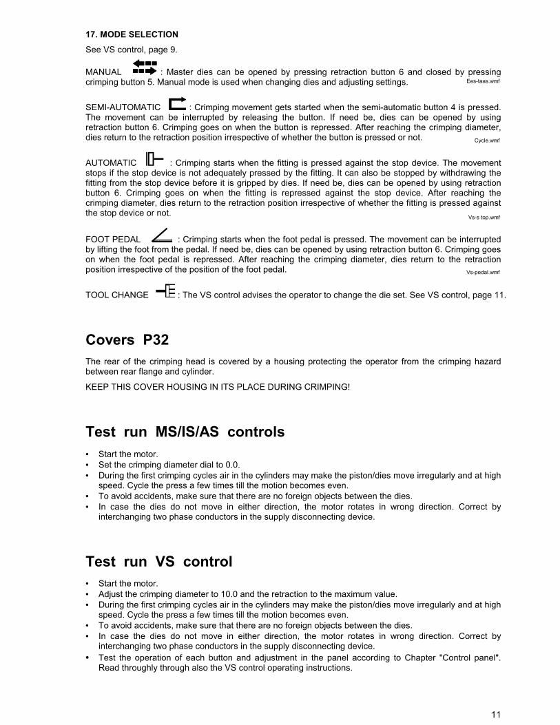
17. MODE SELECTIONSee VS control, page 9.
MANUAL : Master dies can be opened by pressing retraction button 6 and closed by pressingcrimping button 5. Manual mode is used when changing dies and adjusting settings.
SEMI-AUTOMATIC : Crimping movement gets started when the semi-automatic button 4 is pressed.The movement can be interrupted by releasing the button. If need be, dies can be opened by usingretraction button 6. Crimping goes on when the button is repressed. After reaching the crimping diameter,dies return to the retraction position irrespective of whether the button is pressed or not.
AUTOMATIC : Crimping starts when the fitting is pressed against the stop device. The movementstops if the stop device is not adequately pressed by the fitting. It can also be stopped by withdrawing thefitting from the stop device before it is gripped by dies. If need be, dies can be opened by using retractionbutton 6. Crimping goes on when the fitting is repressed against the stop device. After reaching thecrimping diameter, dies return to the retraction position irrespective of whether the fitting is pressed againstthe stop device or not.
FOOT PEDAL : Crimping starts when the foot pedal is pressed. The movement can be interruptedby lifting the foot from the pedal. If need be, dies can be opened by using retraction button 6. Crimping goeson when the foot pedal is repressed. After reaching the crimping diameter, dies return to the retractionposition irrespective of the position of the foot pedal.
TOOL CHANGE : The VS control advises the operator to change the die set. See VS control, page 11.
Covers P32The rear of the crimping head is covered by a housing protecting the operator from the crimping hazardbetween rear flange and cylinder.
KEEP THIS COVER HOUSING IN ITS PLACE DURING CRIMPING!
Test run MS/IS/AS controls• Start the motor.• Set the crimping diameter dial to 0.0.• During the first crimping cycles air in the cylinders may make the piston/dies move irregularly and at high
speed. Cycle the press a few times till the motion becomes even.• To avoid accidents, make sure that there are no foreign objects between the dies.• In case the dies do not move in either direction, the motor rotates in wrong direction. Correct by
interchanging two phase conductors in the supply disconnecting device.
Test run VS control• Start the motor.• Adjust the crimping diameter to 10.0 and the retraction to the maximum value.• During the first crimping cycles air in the cylinders may make the piston/dies move irregularly and at high
speed. Cycle the press a few times till the motion becomes even.• To avoid accidents, make sure that there are no foreign objects between the dies.• In case the dies do not move in either direction, the motor rotates in wrong direction. Correct by
interchanging two phase conductors in the supply disconnecting device.• Test the operation of each button and adjustment in the panel according to Chapter "Control panel".
Read throughly through also the VS control operating instructions.
Ees-taas.wmf
Cycle.wmf
Vs-pedal.wmf
Vs-s top.wmf
12
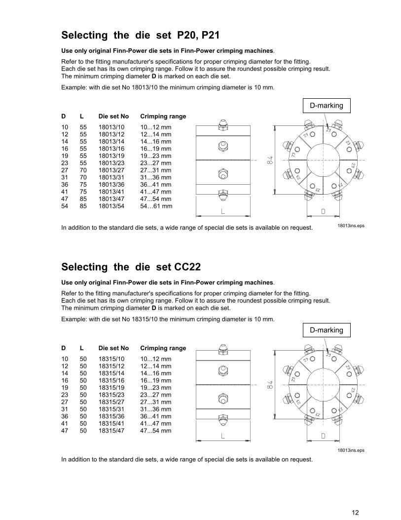
Selecting the die set P20, P21Use only original Finn-Power die sets in Finn-Power crimping machines.
Refer to the fitting manufacturer's specifications for proper crimping diameter for the fitting.Each die set has its own crimping range. Follow it to assure the roundest possible crimping result.The minimum crimping diameter D is marked on each die set.
Example: with die set No 18013/10 the minimum crimping diameter is 10 mm.
D L Die set No Crimping range10 55 18013/10 10...12 mm12 55 18013/12 12...14 mm14 55 18013/14 14...16 mm16 55 18013/16 16...19 mm19 55 18013/19 19...23 mm23 55 18013/23 23...27 mm27 70 18013/27 27...31 mm31 70 18013/31 31...36 mm36 75 18013/36 36...41 mm41 75 18013/41 41...47 mm47 85 18013/47 47...54 mm54 85 18013/54 54…61 mm
In addition to the standard die sets, a wide range of special die sets is available on request.
Selecting the die set CC22Use only original Finn-Power die sets in Finn-Power crimping machines.
Refer to the fitting manufacturer's specifications for proper crimping diameter for the fitting.Each die set has its own crimping range. Follow it to assure the roundest possible crimping result.The minimum crimping diameter D is marked on each die set.
Example: with die set No 18315/10 the minimum crimping diameter is 10 mm.
D L Die set No Crimping range10 50 18315/10 10...12 mm12 50 18315/12 12...14 mm14 50 18315/14 14...16 mm16 50 18315/16 16...19 mm19 50 18315/19 19...23 mm23 50 18315/23 23...27 mm27 50 18315/27 27...31 mm31 50 18315/31 31...36 mm36 50 18315/36 36...41 mm41 50 18315/41 41...47 mm47 50 18315/47 47...54 mm
In addition to the standard die sets, a wide range of special die sets is available on request.
D-marking
18013ins.eps
D-marking
18013ins.eps
13
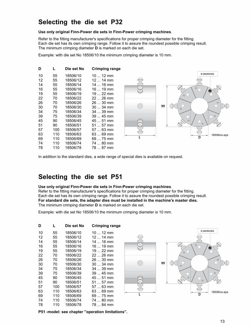
Selecting the die set P32Use only original Finn-Power die sets in Finn-Power crimping machines.
Refer to the fitting manufacturer's specifications for proper crimping diameter for the fitting.Each die set has its own crimping range. Follow it to assure the roundest possible crimping result.The minimum crimping diameter D is marked on each die set.
Example: with die set No 18506/10 the minimum crimping diameter is 10 mm.
D L Die set No Crimping range
10 55 18506/10 10 ... 12 mm12 55 18506/12 12 ... 14 mm14 55 18506/14 14 ... 16 mm16 55 18506/16 16 ... 19 mm19 55 18506/19 19 ... 22 mm22 70 18506/22 22 ... 26 mm26 70 18506/26 26 ... 30 mm30 70 18506/30 30 ... 34 mm34 75 18506/34 34 ... 39 mm39 75 18506/39 39 ... 45 mm45 90 18506/45 45 ... 51 mm51 90 18506/51 51 ... 57 mm57 100 18506/57 57 ... 63 mm63 110 18506/63 63 ... 69 mm69 110 18506/69 69 ... 75 mm74 110 18506/74 74 ... 80 mm78 110 18506/78 78 ... 87 mm
In addition to the standard dies, a wide range of special dies is available on request.
Selecting the die set P51Use only original Finn-Power die sets in Finn-Power crimping machines.Refer to the fitting manufacturer's specifications for proper crimping diameter for the fitting.Each die set has its own crimping range. Follow it to assure the roundest possible crimping result.For standard die sets, the adapter dies must be installed in the machine's master dies.The minimum crimping diameter D is marked on each die set.
Example: with die set No 18506/10 the minimum crimping diameter is 10 mm.
D L Die set No Crimping range
10 55 18506/10 10 ... 12 mm12 55 18506/12 12 ... 14 mm14 55 18506/14 14 ... 16 mm16 55 18506/16 16 ... 19 mm19 55 18506/19 19 ... 22 mm22 70 18506/22 22 ... 26 mm26 70 18506/26 26 ... 30 mm30 70 18506/30 30 ... 34 mm34 75 18506/34 34 ... 39 mm39 75 18506/39 39 ... 45 mm45 90 18506/45 45 ... 51 mm51 90 18506/51 51 ... 57 mm57 100 18506/57 57 ... 63 mm63 110 18506/63 63 ... 69 mm69 110 18506/69 69 ... 75 mm74 110 18506/74 74 ... 80 mm78 110 18506/78 78 ... 84 mm
P51 -model: see chapter ”operation limitations”.
18506ins.eps
18506ins.eps
14
FP140 DIE SETS FOR P51 -MODELFP140 die sets for large fittings are attached directly to the master dies. FP140 die sets are manufacturedwith following dimensions:
D L Die set No Crimping range
84 110 18860/84 84 ... 92 mm 92 110 18860/92 92 ... 100 mm100 110 18860/100 100 ... 108 mm108 110 18860/108 108 ... 116 mm116 110 18860/116 116 ... 124 mm
In addition to the standard die sets and FP140 die sets, a wide range of special die sets are available onrequest.
Installing the die set
QUICK CHANGE MS/IS/AS(OPTION)
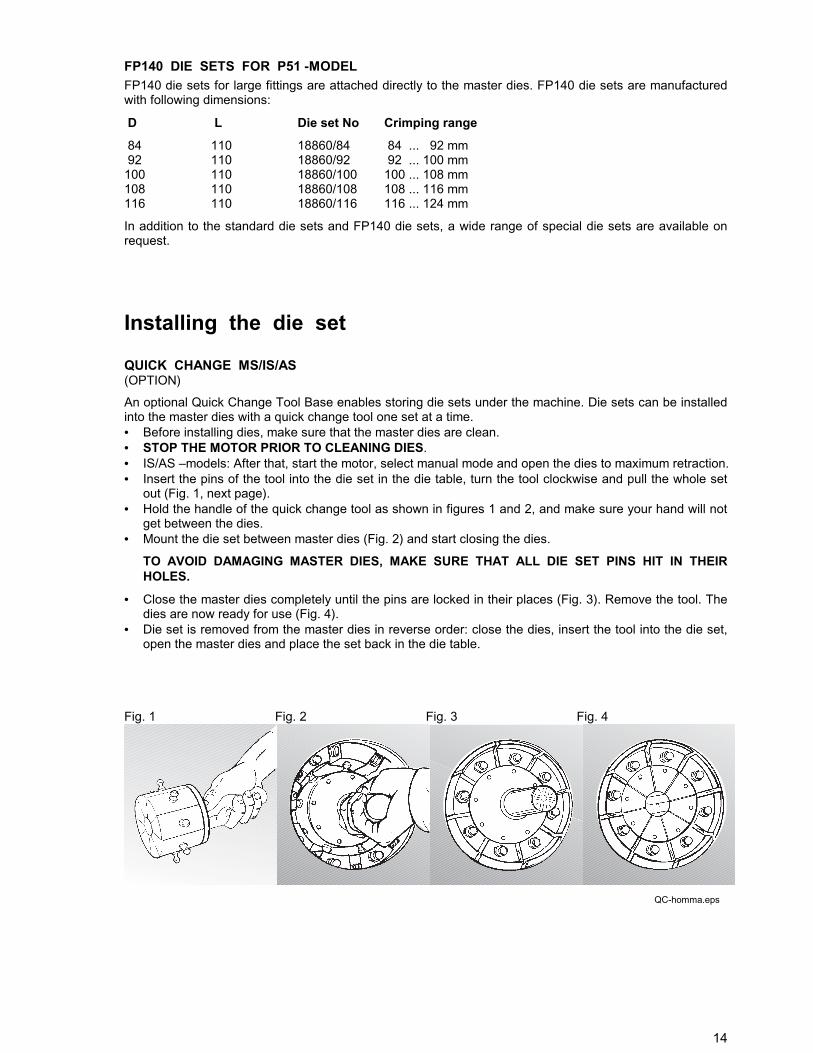
An optional Quick Change Tool Base enables storing die sets under the machine. Die sets can be installedinto the master dies with a quick change tool one set at a time.• Before installing dies, make sure that the master dies are clean.• STOP THE MOTOR PRIOR TO CLEANING DIES.• IS/AS –models: After that, start the motor, select manual mode and open the dies to maximum retraction.• Insert the pins of the tool into the die set in the die table, turn the tool clockwise and pull the whole set
out (Fig. 1, next page).• Hold the handle of the quick change tool as shown in figures 1 and 2, and make sure your hand will not
get between the dies.• Mount the die set between master dies (Fig. 2) and start closing the dies.
TO AVOID DAMAGING MASTER DIES, MAKE SURE THAT ALL DIE SET PINS HIT IN THEIRHOLES.
• Close the master dies completely until the pins are locked in their places (Fig. 3). Remove the tool. Thedies are now ready for use (Fig. 4).
• Die set is removed from the master dies in reverse order: close the dies, insert the tool into the die set,open the master dies and place the set back in the die table.
Fig. 1 Fig. 2 Fig. 3 Fig. 4
QC-homma.eps
15
QUICK CHANGE VS(OPTION)An optional Quick Change Tool Base enables storing die sets under the machine. Die sets can be installedinto the master dies with a quick change tool one set at a time.
• Before installing dies, make sure that the master dies are clean.• STOP THE MOTOR PRIOR TO CLEANING DIES.• Select TOOL CHANGE MODE.• See also VS control, Chapter "Tool change screen" on page 11.• Open the dies to maximum retraction.• Insert the pins of the tool into the die set in the die table, turn the tool clockwise and pull the whole set
out (Fig. 1).• Hold the handle of the quick change tool as shown in figures 1 and 2, and make sure your hand will not
get between the dies.• Mount the die set between master dies (Fig. 2) and start closing the dies.
TO AVOID DAMAGING MASTER DIES, MAKE SURE THAT ALL DIE SET PINS HIT IN THEIR HOLES. • Close the master dies completely until the pins are locked in their places (Fig. 3).• Remove the tool (Fig. 4). Open the dies to the retraction position. The dies are now ready for use.• Die set is removed from the press in reverse order: close the dies, insert the tool into the die set, open
the master dies and place the set back in the table.
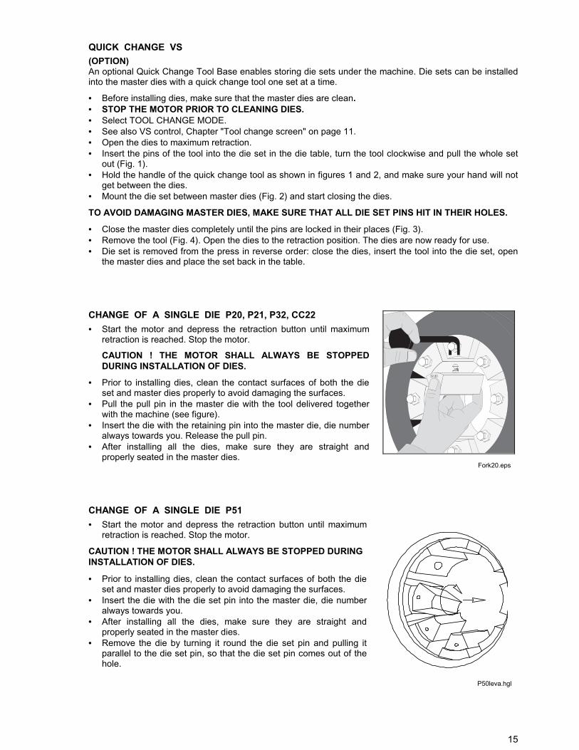
CHANGE OF A SINGLE DIE P20, P21, P32, CC22• Start the motor and depress the retraction button until maximum
retraction is reached. Stop the motor.
CAUTION ! THE MOTOR SHALL ALWAYS BE STOPPEDDURING INSTALLATION OF DIES.
• Prior to installing dies, clean the contact surfaces of both the dieset and master dies properly to avoid damaging the surfaces.
• Pull the pull pin in the master die with the tool delivered togetherwith the machine (see figure).
• Insert the die with the retaining pin into the master die, die numberalways towards you. Release the pull pin.
• After installing all the dies, make sure they are straight andproperly seated in the master dies.
CHANGE OF A SINGLE DIE P51• Start the motor and depress the retraction button until maximum
retraction is reached. Stop the motor.
CAUTION ! THE MOTOR SHALL ALWAYS BE STOPPED DURINGINSTALLATION OF DIES.
• Prior to installing dies, clean the contact surfaces of both the dieset and master dies properly to avoid damaging the surfaces.
• Insert the die with the die set pin into the master die, die numberalways towards you.
• After installing all the dies, make sure they are straight andproperly seated in the master dies.
• Remove the die by turning it round the die set pin and pulling itparallel to the die set pin, so that the die set pin comes out of thehole.
Fork20.eps
P50leva.hgl
16
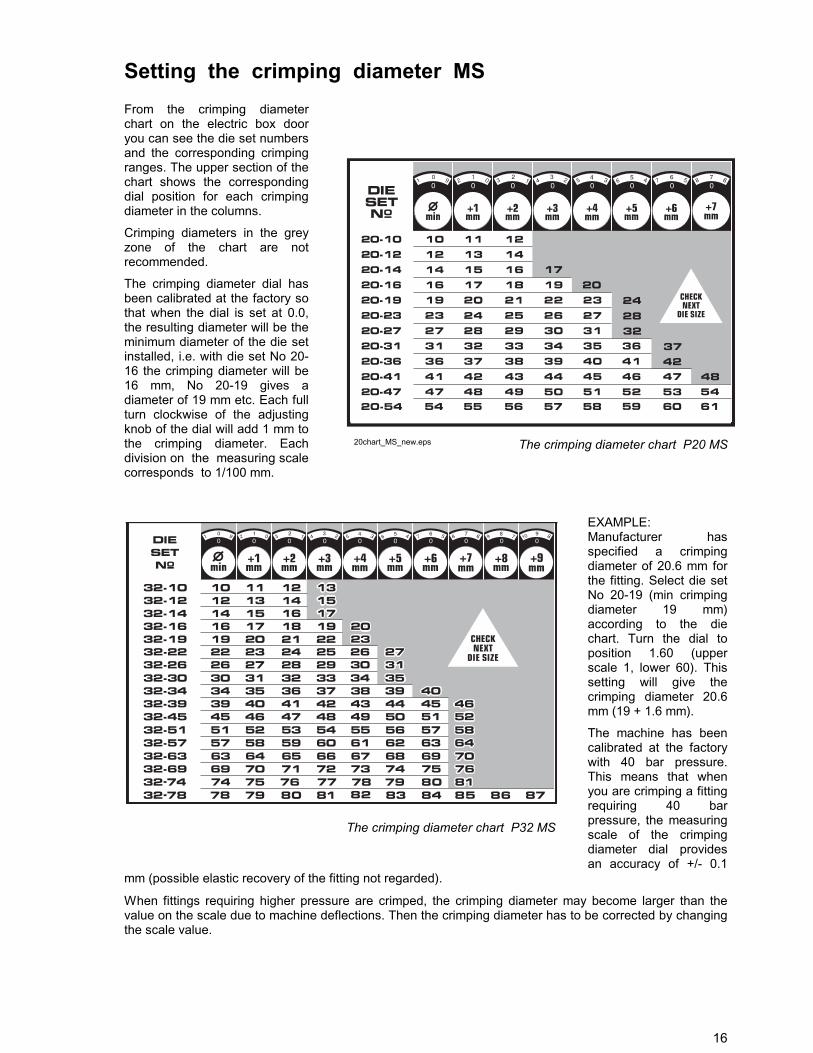
Setting the crimping diameter MSFrom the crimping diameterchart on the electric box dooryou can see the die set numbersand the corresponding crimpingranges. The upper section of thechart shows the correspondingdial position for each crimpingdiameter in the columns.
Crimping diameters in the greyzone of the chart are notrecommended.
The crimping diameter dial hasbeen calibrated at the factory sothat when the dial is set at 0.0,the resulting diameter will be theminimum diameter of the die setinstalled, i.e. with die set No 20-16 the crimping diameter will be16 mm, No 20-19 gives adiameter of 19 mm etc. Each fullturn clockwise of the adjustingknob of the dial will add 1 mm tothe crimping diameter. Eachdivision on the measuring scalecorresponds to 1/100 mm.
EXAMPLE:Manufacturer hasspecified a crimpingdiameter of 20.6 mm forthe fitting. Select die setNo 20-19 (min crimpingdiameter 19 mm)according to the diechart. Turn the dial toposition 1.60 (upperscale 1, lower 60). Thissetting will give thecrimping diameter 20.6mm (19 + 1.6 mm).
The machine has beencalibrated at the factorywith 40 bar pressure.This means that whenyou are crimping a fittingrequiring 40 barpressure, the measuringscale of the crimpingdiameter dial providesan accuracy of +/- 0.1
mm (possible elastic recovery of the fitting not regarded).
When fittings requiring higher pressure are crimped, the crimping diameter may become larger than thevalue on the scale due to machine deflections. Then the crimping diameter has to be corrected by changingthe scale value.
20chart_MS_new.eps The crimping diameter chart P20 MS
The crimping diameter chart P32 MS
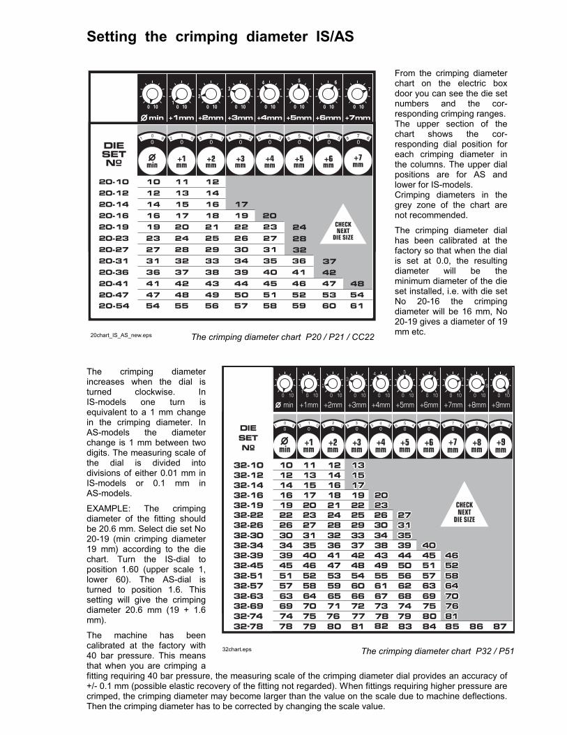
Setting the crimping diameter IS/AS
From the crimping diameterchart on the electric boxdoor you can see the die setnumbers and the cor-responding crimping ranges.The upper section of thechart shows the cor-responding dial position foreach crimping diameter inthe columns. The upper dialpositions are for AS andlower for IS-models.Crimping diameters in thegrey zone of the chart arenot recommended.
The crimping diameter dialhas been calibrated at thefactory so that when the dialis set at 0.0, the resultingdiameter will be theminimum diameter of the dieset installed, i.e. with die setNo 20-16 the crimpingdiameter will be 16 mm, No20-19 gives a diameter of 19mm etc.
The crimping diameterincreases when the dial isturned clockwise. InIS-models one turn isequivalent to a 1 mm changein the crimping diameter. InAS-models the diameterchange is 1 mm between twodigits. The measuring scale ofthe dial is divided intodivisions of either 0.01 mm inIS-models or 0.1 mm inAS-models.
EXAMPLE: The crimpingdiameter of the fitting shouldbe 20.6 mm. Select die set No20-19 (min crimping diameter19 mm) according to the diechart. Turn the IS-dial toposition 1.60 (upper scale 1,lower 60). The AS-dial isturned to position 1.6. Thissetting will give the crimpingdiameter 20.6 mm (19 + 1.6mm).
The machine has beencalibrated at the factory with40 bar pressure. This meansthat when you are crimping afitting requiring 40 bar pressure, the measuring scale of the crimping diameter dial provides an accuracy of+/- 0.1 mm (possible elastic recovery of the fitting not regarded). When fittings requiring higher pressure arecrimped, the crimping diameter may become larger than the value on the scale due to machine deflections.Then the crimping diameter has to be corrected by changing the scale value.
32chart.eps The crimping diameter chart P32 / P51
20chart_IS_AS_new.eps The crimping diameter chart P20 / P21 / CC22
Setting the crimping diameter VS• While the crimping diameter display is surrounded by the cursor, activate it by pressing E.• Select the desired crimping diameter by turning the selector and press E.• Check the die set used and change it if need be.• When required, set the retraction diameter in the same way.
The machine has been calibrated at the factory with 40 bar pressure. This means that when you arecrimping a fitting requiring 40 bar pressure, the measuring scale of the crimping diameter dial provides anaccuracy of +/- 0.1 mm (possible elastic recovery of the fitting not regarded).
When fittings requiring higher pressure are crimped, the crimping diameter may become larger than thevalue on the scale due to machine deflections. Then the crimping diameter has to be corrected using thecorrection function.
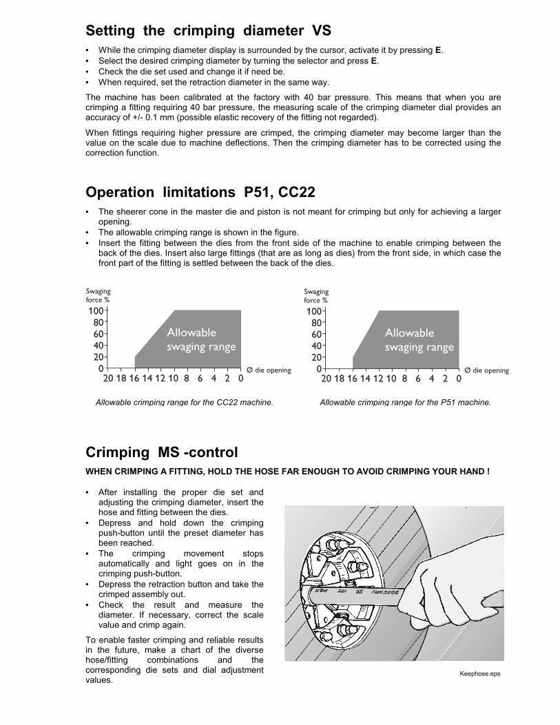
Operation limitations P51, CC22• The sheerer cone in the master die and piston is not meant for crimping but only for achieving a larger
opening.• The allowable crimping range is shown in the figure.• Insert the fitting between the dies from the front side of the machine to enable crimping between the
back of the dies. Insert also large fittings (that are as long as dies) from the front side, in which case thefront part of the fitting is settled between the back of the dies.
Crimping MS -controlWHEN CRIMPING A FITTING, HOLD THE HOSE FAR ENOUGH TO AVOID CRIMPING YOUR HAND !
• After installing the proper die set andadjusting the crimping diameter, insert thehose and fitting between the dies.
• Depress and hold down the crimpingpush-button until the preset diameter hasbeen reached.
• The crimping movement stopsautomatically and light goes on in thecrimping push-button.
• Depress the retraction button and take thecrimped assembly out.
• Check the result and measure thediameter. If necessary, correct the scalevalue and crimp again.
To enable faster crimping and reliable resultsin the future, make a chart of the diversehose/fitting combinations and thecorresponding die sets and dial adjustmentvalues.
Keephose.eps
Allowable crimping range for the CC22 machine. Allowable crimping range for the P51 machine.
19
Crimping IS/AS/VS -controlsWHEN CRIMPING A FITTING, HOLD THE HOSE FAR ENOUGH TO AVOID CRIMPING YOUR HAND !
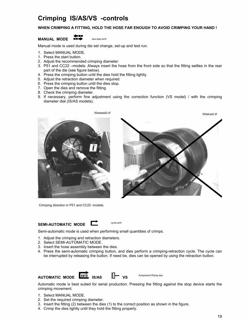
MANUAL MODE Manual mode is used during die set change, set-up and test run.
1. Select MANUAL MODE.1. Press the start button.2. Adjust the recommended crimping diameter.3. P51 and CC22 –models: Always insert the hose from the front side so that the fitting settles in the rear
part of the die (see figure below).4. Press the crimping button until the dies hold the fitting lightly.5. Adjust the retraction diameter when required.6. Press the crimping button until the dies stop.7. Open the dies and remove the fitting.8. Check the crimping diameter.9. If necessary, perform fine adjustment using the correction function (VS model) / with the crimping
diameter dial (IS/AS models).
SEMI-AUTOMATIC MODE Semi-automatic mode is used when performing small quantities of crimps.
1. Adjust the crimping and retraction diameters.2. Select SEMI-AUTOMATIC MODE.3. Insert the hose assembly between the dies.4. Press the semi-automatic crimping button, and dies perform a crimping-retraction cycle. The cycle can
be interrupted by releasing the button. If need be, dies can be opened by using the retraction button.
AUTOMATIC MODE IS/AS VSAutomatic mode is best suited for serial production. Pressing the fitting against the stop device starts thecrimping movement.
1. Select MANUAL MODE.2. Set the required crimping diameter.3. Insert the fitting (2) between the dies (1) to the correct position as shown in the figure.4. Crimp the dies lightly until they hold the fitting properly.
50edestä2.tif 50takaa2.tif
Autopress/VSstop.eps
Crimping direction in P51 and CC22 -models.
ees-taas.wmf
cycle.wmf

5. P20, P21 and P32 –models: Loosen the locking nut (3) and push the stop device (4) against the fitting
so that the spring-loaded stop device is compressed, making the limit switch inside it actuate. Tightenthe locking nut.CC22 and P51 –models: Loosen the locking lever (3) and push the stop device (4) against the fitting sothat the spring-loaded stop device is compressed, making the limit switch inside it actuate. Tighten thelocking lever.
6. Open the dies until the fitting loosens.7. Select AUTOMATIC MODE.8. When the stop device is pressed, the machine performs a crimp and returns to the set retraction.9. The movement stops if the fitting is not adequately pressed against the stop device. If need be, dies can
be opened by using the retraction button.10. After dies have gripped the fitting, the crimping movement can be stopped only by the emergency stop
push-button.11. Make sure that there are no foreign objects between the dies.12. Make a test crimp by pressing the fitting against the stop device.13. Check the crimping diameter and correct the position of the stop device if necessary.
To protect your hands from getting crimped, don't ever touch the stop device !
AUTOMATIC MODE / FOOT PEDAL IS/AS VS(OPTION)
As an alternative, a foot pedal can be installed in the stop device plug, e.g. when large fittings are crimpedand more space is needed behind the machine. The foot pedal enables holding the hose assembly withboth hands.In FOOT PEDAL mode dies will move as long as the pedal is pressed or till the set crimping diameter hasbeen reached. The crimping movement can be interrupted by lifting the foot from the pedal. If need be, diescan be opened by using the retraction button.
Adjustment of retraction diameter IS/AS1. Turn the mode selector to 0-position.2. Start the machine by pressing the start button.3. Select manual mode.4. Press the crimping button until the dies completely close.5. Turn the retraction diameter control dial counterclockwise up to the minimum.6. Select semi-automatic mode.7. Turn the retraction diameter control dial gradually clockwise. While the dial is turned, the dies will open.
Insert the uncrimped fitting between the dies as soon as the opening is large enough. Release theretraction diameter control dial at that position, which then becomes the final setting.
P20, P21 and P32 -models CC22 and P51 -models
p50stop.hgl20stopp.jpg
foot-pdl.wmf//VS-pedal.wmf
21
If the machine does not work...• Make sure the supply disconnecting device is in position 1.• Check that the plug is in the socket.• MS –model: If the motor is running but the machine does not crimp, check that the crimping diameter
dial is plugged in.• IS/AS –models: In automatic modes the dies must be in the retraction position (signal lamp 8 illuminated),
otherwise the crimping cycle will not get started.• VS –model: If the motor is running but the machine does not crimp, check that the crimping diameter dial
is plugged in.• If still not working, contact a serviceman.
PREVENTIVE MAINTENANCE• The following maintenance operations can be performed by the operator according to the instructions
below. However, electrical works and repairs like changing seals or the pump must only be carried outby a qualified specialist.
• PRIOR TO ANY SERVICING OPERATION, TURN THE SUPPLY DISCONNECTING DEVICE TOPOSITION '0'.
• BEFORE CHANGING THE MOTOR CIRCUIT BREAKER OR UNDERVOLTAGE TRIP, DISCONNECTTHE PLUG OR SUPPLY CABLE FROM THE MAINS !
• Open the dies to maximum retraction before servicing.
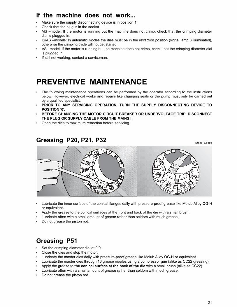
Greasing P20, P21, P32
• Lubricate the inner surface of the conical flanges daily with pressure-proof grease like Molub Alloy OG-Hor equivalent.
• Apply the grease to the conical surfaces at the front and back of the die with a small brush.• Lubricate often with a small amount of grease rather than seldom with much grease.• Do not grease the piston rod.
Greasing P51• Set the crimping diameter dial at 0.0.• Close the dies and stop the motor.• Lubricate the master dies daily with pressure-proof grease like Molub Alloy OG-H or equivalent.• Lubricate the master dies through 16 grease nipples using a compressor gun (alike as CC22 greasing).• Apply the grease to the conical surface at the back of the die with a small brush (alike as CC22).• Lubricate often with a small amount of grease rather than seldom with much grease.• Do not grease the piston rod.
Greas_32.eps
22
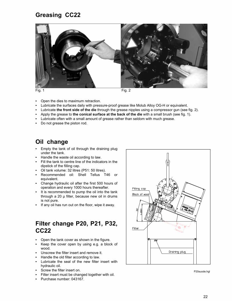
Greasing CC22
Fig. 1 Fig. 2
• Open the dies to maximum retraction.• Lubricate the surfaces daily with pressure-proof grease like Molub Alloy OG-H or equivalent.• Lubricate the front side of the die through the grease nipples using a compressor gun (see fig. 2).• Apply the grease to the conical surface at the back of the die with a small brush (see fig. 1).• Lubricate often with a small amount of grease rather than seldom with much grease.• Do not grease the piston rod.
Oil change• Empty the tank of oil through the draining plug
under the tank.• Handle the waste oil according to law.• Fill the tank to centre line of the indicators in the
dipstick of the filling cap.• Oil tank volume: 32 litres (P51: 50 litres).• Recommended oil: Shell Tellus T46 or
equivalent.• Change hydraulic oil after the first 500 hours of
operation and every 1000 hours thereafter.• It is recommended to pump the oil into the tank
through a 20 µ filter, because new oil in drumsis not pure.
• If any oil has run out on the floor, wipe it away.
Filter change P20, P21, P32,CC22 • Open the tank cover as shown in the figure.• Keep the cover open by using e.g. a block of
wood.• Unscrew the filter insert and remove it.• Handle the old filter according to law.• Lubricate the seal of the new filter insert with
hydraulic oil.• Screw the filter insert on.• Filter insert must be changed together with oil.• Purchase number: 043167.
P20suode.hgl
23
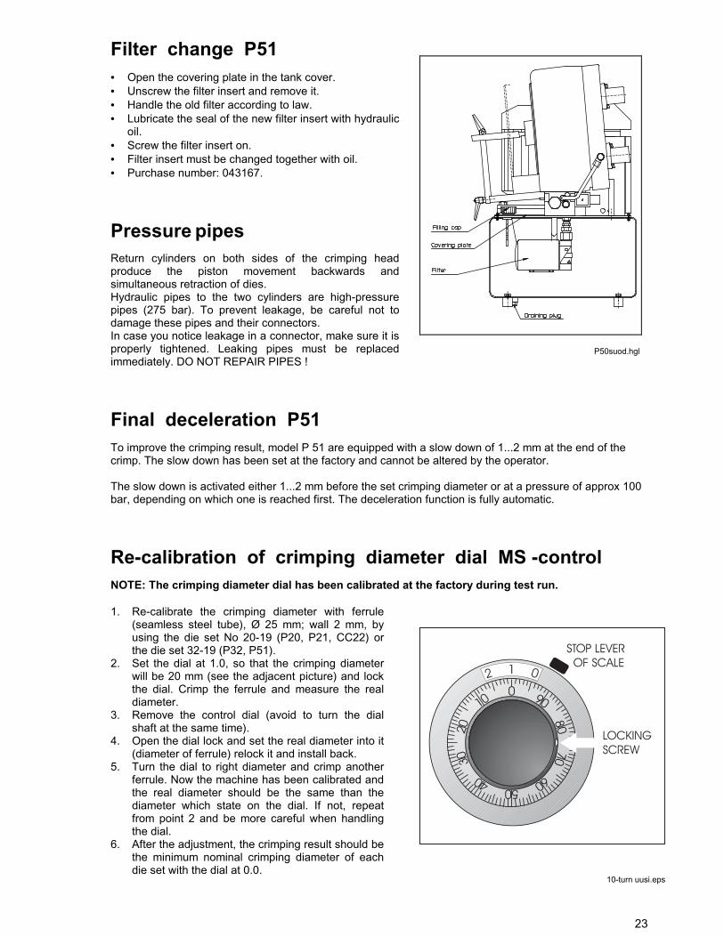
Filter change P51 • Open the covering plate in the tank cover.• Unscrew the filter insert and remove it.• Handle the old filter according to law.• Lubricate the seal of the new filter insert with hydraulic
oil.• Screw the filter insert on.• Filter insert must be changed together with oil.• Purchase number: 043167.
Pressure pipesReturn cylinders on both sides of the crimping headproduce the piston movement backwards andsimultaneous retraction of dies.Hydraulic pipes to the two cylinders are high-pressurepipes (275 bar). To prevent leakage, be careful not todamage these pipes and their connectors.In case you notice leakage in a connector, make sure it isproperly tightened. Leaking pipes must be replacedimmediately. DO NOT REPAIR PIPES !
Final deceleration P51To improve the crimping result, model P 51 are equipped with a slow down of 1...2 mm at the end of thecrimp. The slow down has been set at the factory and cannot be altered by the operator.
The slow down is activated either 1...2 mm before the set crimping diameter or at a pressure of approx 100bar, depending on which one is reached first. The deceleration function is fully automatic.
Re-calibration of crimping diameter dial MS -controlNOTE: The crimping diameter dial has been calibrated at the factory during test run.
1. Re-calibrate the crimping diameter with ferrule(seamless steel tube), Ø 25 mm; wall 2 mm, byusing the die set No 20-19 (P20, P21, CC22) orthe die set 32-19 (P32, P51).
2. Set the dial at 1.0, so that the crimping diameterwill be 20 mm (see the adjacent picture) and lockthe dial. Crimp the ferrule and measure the realdiameter.
3. Remove the control dial (avoid to turn the dialshaft at the same time).
4. Open the dial lock and set the real diameter into it(diameter of ferrule) relock it and install back.
5. Turn the dial to right diameter and crimp anotherferrule. Now the machine has been calibrated andthe real diameter should be the same than thediameter which state on the dial. If not, repeatfrom point 2 and be more careful when handlingthe dial.
6. After the adjustment, the crimping result should bethe minimum nominal crimping diameter of eachdie set with the dial at 0.0.
P50suod.hgl
10-turn uusi.eps
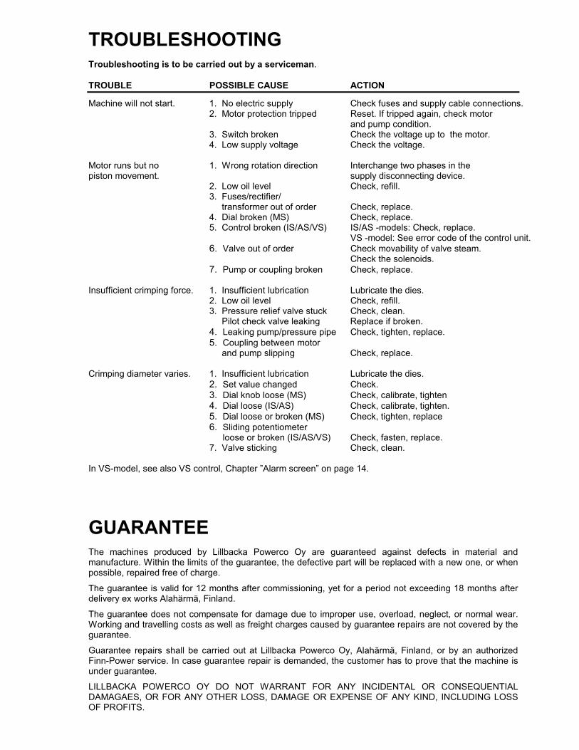
TROUBLESHOOTINGTroubleshooting is to be carried out by a serviceman.
TROUBLE POSSIBLE CAUSE ACTION
Machine will not start. 1. No electric supply Check fuses and supply cable connections.2. Motor protection tripped Reset. If tripped again, check motor
and pump condition. 3. Switch broken Check the voltage up to the motor.
4. Low supply voltage Check the voltage.
Motor runs but no 1. Wrong rotation direction Interchange two phases in thepiston movement. supply disconnecting device.
2. Low oil level Check, refill.3. Fuses/rectifier/ transformer out of order Check, replace.4. Dial broken (MS) Check, replace.
5. Control broken (IS/AS/VS) IS/AS -models: Check, replace. VS -model: See error code of the control unit.
6. Valve out of order Check movability of valve steam.Check the solenoids.
7. Pump or coupling broken Check, replace.
Insufficient crimping force. 1. Insufficient lubrication Lubricate the dies.2. Low oil level Check, refill.3. Pressure relief valve stuck Check, clean. Pilot check valve leaking Replace if broken.4. Leaking pump/pressure pipe Check, tighten, replace.5. Coupling between motor and pump slipping Check, replace.
Crimping diameter varies. 1. Insufficient lubrication Lubricate the dies.2. Set value changed Check.3. Dial knob loose (MS) Check, calibrate, tighten4. Dial loose (IS/AS) Check, calibrate, tighten.5. Dial loose or broken (MS) Check, tighten, replace6. Sliding potentiometer
loose or broken (IS/AS/VS) Check, fasten, replace. 7. Valve sticking Check, clean.
In VS-model, see also VS control, Chapter ”Alarm screen” on page 14.
GUARANTEEThe machines produced by Lillbacka Powerco Oy are guaranteed against defects in material andmanufacture. Within the limits of the guarantee, the defective part will be replaced with a new one, or whenpossible, repaired free of charge.
The guarantee is valid for 12 months after commissioning, yet for a period not exceeding 18 months afterdelivery ex works Alahärmä, Finland.
The guarantee does not compensate for damage due to improper use, overload, neglect, or normal wear.Working and travelling costs as well as freight charges caused by guarantee repairs are not covered by theguarantee.
Guarantee repairs shall be carried out at Lillbacka Powerco Oy, Alahärmä, Finland, or by an authorizedFinn-Power service. In case guarantee repair is demanded, the customer has to prove that the machine isunder guarantee.
LILLBACKA POWERCO OY DO NOT WARRANT FOR ANY INCIDENTAL OR CONSEQUENTIALDAMAGAES, OR FOR ANY OTHER LOSS, DAMAGE OR EXPENSE OF ANY KIND, INCLUDING LOSSOF PROFITS.
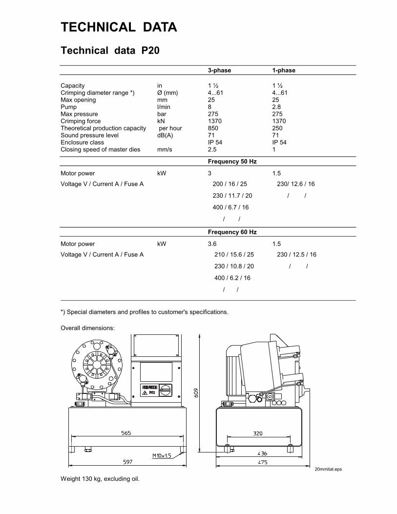
TECHNICAL DATATechnical data P20
3-phase 1-phase
Capacity in 1 ½ 1 ½Crimping diameter range *) Ø (mm) 4...61 4...61Max opening mm 25 25Pump l/min 8 2.8Max pressure bar 275 275Crimping force kN 1370 1370Theoretical production capacity per hour 850 250Sound pressure level dB(A) 71 71Enclosure class IP 54 IP 54Closing speed of master dies mm/s 2.5 1
Frequency 50 Hz
Motor power kW 3 1.5
Voltage V / Current A / Fuse A � 200 / 16 / 25 � 230/ 12.6 / 16
� 230 / 11.7 / 20 � / /
� 400 / 6.7 / 16
� / /
Frequency 60 Hz
Motor power kW 3.6 1.5
Voltage V / Current A / Fuse A � 210 / 15.6 / 25 � 230 / 12.5 / 16
� 230 / 10.8 / 20 � / /
� 400 / 6.2 / 16
� / /
*) Special diameters and profiles to customer's specifications.
Overall dimensions:
Weight 130 kg, excluding oil.20mmitat.eps

READ THE INSTRUCTIONS THOROUGHLY TO SECURE SAFE AND CORRECTOPERATION OF THE MACHINE.

27
Technical data P21
3-phase 1-phase
Capacity in 1 ½ 1 ½Crimping diameter range *) Ø (mm) 4...61 4...61Max opening mm 34 34Pump l/min 8 2.8Max pressure bar 275 275Crimping force kN 1370 1370Theoretical production capacity per hour 850 250Sound pressure level dB(A) 71 71Enclosure class IP 54 IP 54Closing speed of master dies mm/s 2.5 1
Frequency 50 Hz
Motor power kW 3 1.5
Voltage V / Current A / Fuse A � 200 / 16 / 25 � 230/ 12.6 / 16
� 230 / 11.7 / 20 � / /
� 400 / 6.7 / 16
� / /
Frequency 60 Hz
Motor power kW 3.6 1.5
Voltage V / Current A / Fuse A � 210 / 15.6 / 25 � 230 / 12.5 / 16
� 230 / 10.8 / 20 � / /
� 400 / 6.2 / 16
� / /
*) Special diameters and profiles to customer's specifications.
Overall dimensions:
Weight 186 kg, excluding oil.P21mit.hgl

28
READ THE INSTRUCTIONS THOROUGHLY TO SECURE SAFE AND CORRECTOPERATION OF THE MACHINE.
29
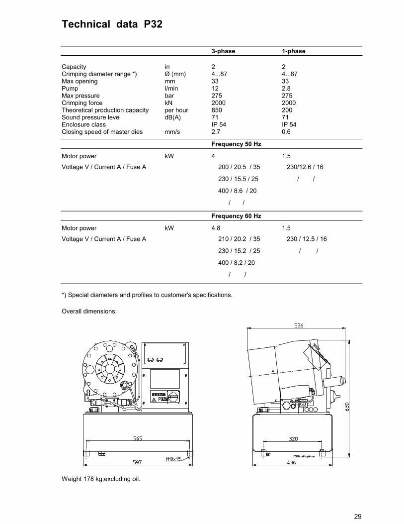
Technical data P32
3-phase 1-phase
Capacity in 2 2Crimping diameter range *) Ø (mm) 4...87 4...87Max opening mm 33 33Pump l/min 12 2.8Max pressure bar 275 275Crimping force kN 2000 2000Theoretical production capacity per hour 850 200Sound pressure level dB(A) 71 71Enclosure class IP 54 IP 54Closing speed of master dies mm/s 2.7 0.6
Frequency 50 Hz
Motor power kW 4 1.5
Voltage V / Current A / Fuse A � 200 / 20.5 / 35 � 230/12.6 / 16
� 230 / 15.5 / 25 � / /
� 400 / 8.6 / 20
� / /
Frequency 60 Hz
Motor power kW 4.8 1.5
Voltage V / Current A / Fuse A � 210 / 20.2 / 35 � 230 / 12.5 / 16
� 230 / 15.2 / 25 � / /
� 400 / 8.2 / 20
� / /
*) Special diameters and profiles to customer's specifications.
Overall dimensions:
Weight 178 kg,excluding oil.

30
READ THE INSTRUCTIONS THOROUGHLY TO SECURE SAFE AND CORRECTOPERATION OF THE MACHINE.
Technical data P51
3-phase
Capacity in 2 ½ (industrial hose 4”)Crimping diameter range *) Ø (mm) 4....120Max opening mm 46Pump l/min 18/6Max pressure bar 300Crimping force kN 2800Theoretical production capacity per hour 720Sound pressure level dB(A) 71Enclosure class IP 54Closing speed of master dies (max.) mm/s 9.2
Frequency 50 Hz
Motor power kW 4
Voltage V / Current A / Fuse A � / /
� 230 / 15.3 / 25
� 400 / 8.8 / 20
� / /
Frequency 60 Hz
Motor power kW 4.8
Voltage V / Current A / Fuse A � / /
� 230 / 15.2 / 25
� 400 / 8.7 / 20
� / /
*) with complete standard die equipment. Special diameters and profiles to customer's specifications.
Overall dimensions:
P50mit.hgl

31
Weight 260 kg, excluding oil.
READ THE INSTRUCTIONS THOROUGHLY TO SECURE SAFE AND CORRECTOPERATION OF THE MACHINE.
P50mit.hgl

32
Technical data CC22
3-phase 1-phase
Capacity in 1 ¼ 1 ¼Crimping diameter range *) Ø (mm) 4...54 4...54Max opening mm 25 25Pump l/min 8 2.8Max pressure bar 275 275Crimping force kN 680 680Theoretical production capacity per hour 1700 500Sound pressure level dB(A) 71 71Enclosure class IP 54 IP 54Closing speed of master dies mm/s 5 2
Frequency 50 Hz
Motor power kW 3 1.5
Voltage V / Current A / Fuse A � 200 / 16 / 25 � 230/ 12.6 / 16
� 230 / 11.7 / 20 � / /
� 400 / 6.7 / 16
� / /
Frequency 60 Hz
Motor power kW 3.6 1.5
Voltage V / Current A / Fuse A � 210 / 15.6 / 25 � 230 / 12.5 / 16
� 230 / 10.8 / 20 � / /
� 400 / 6.2 / 16
� / /
*) Special diameters and profiles to customer's specifications.
Overall dimensions:
Weight 125 kg, excluding oil.
20mmitat.eps

33
READ THE INSTRUCTIONS THOROUGHLY TO SECURE SAFE AND CORRECTOPERATION OF THE MACHINE.