operating instructions el870-el9700 embedded line panel-pc
TRANSCRIPT

LDCDS−ELx7xx.Kò;
Ä.Kò;ä
Betriebsanleitung
Operating Instructions
Embedded Line Panel−PC
�
EL 870 − EL 9700
Einbau−Panel−PC mit TFT−Display
Panel PC with TFT display
Industrial PC

� Lesen Sie zuerst diese Anleitung, bevor Sie mit den Arbeiten beginnen!
Beachten Sie die enthaltenen Sicherheitshinweise.
� Please read these instructions before you start working!
Follow the enclosed safety instructions.

-F3
Fail
Power
F1
+F2
Status
��
� �
�
�
�
ELx7xx−001

� 4 LDCDS−ELx7xx DE/EN 4.0
Elemente
Pos. Beschreibung
� Panel−PC (hier EL 5700)
� Frontseitiger USB−Anschluss (Option)
� Schraubspanner
� DVD−Laufwerk (Option)
� Frontseitige Bedien− und Anzeigeelemente
Informationen zur Gültigkeit
Diese Anleitung ist gültig für
ƒ EL 870
ƒ EL 1700, EL 1700s
ƒ EL 1750, EL 1750s
ƒ EL 2700
ƒ EL 2750
ƒ EL 5700
ƒ EL 5720
ƒ EL 5750
ƒ EL 5770
ƒ EL 9700
Identifikation
107AT12345107AT12345
Lenze
D-40667 Meerbusch
certified
P/NL
File Exxxxxx
RC U US14ZZ
LISTEDIND. CONT. EQ.
�
�
�
��
� �
�
DVIUSB−012
� Typbezeichnung� Typschlüssel/Bestellnummer� Technische Daten� Hardware−/Firmware−Version� Materialnummer (kundenspezifisch)� Seriennummer als Barcode� Hersteller Zertifizierung Handzeichen Prüfer

� 5LDCDS−ELx7xx DE/EN 4.0
�
Typenschlüssel 34xx x x x x x x xx x
Gerätetyp3400 = EL 8703401 = EL 17003402 = EL 1700s3403 = EL 27003404 = EL 57003405 = EL 97003406 = EL 57203407 = EL 17503408 = EL 1750s3409 = EL 27503410 = EL 57503411 = EL 5770 (Tastatur deutsch)3412 = EL 5770 (Tastatur englisch)
Front1 = Glasscheibe2 = TouchscreenX = kundenspezifisch
USB−Anschluss, frontseitig0 = ohne1 = mit
Prozessor, lüfterlosL = AMD Geode LX800 / 500 MHz8 = Mobile Intel� Celeron M 600 MHz9 = Mobile Intel� Celeron M 1 GHzProzessor, "Smart Cool"G = AMD Geode LX800 / 500 MHzH = Mobile Intel� Celeron M 600 MHzK = Mobile Intel� Celeron M 1 GHzD = Mobile Intel� Celeron M 1,5 GHzE = Mobile Intel� Celeron M 1,8 GHzF = Intel� Core� Duo 1,66 GHz
Arbeitsspeicher3 = 256 MB4 = 512 MB5 = 1024 MB
Massenspeicher1 = Steckplatz für Compact Flash2 = zusätzlich Festplatte 60 GB3 = zusätzlich Festplatte 40 GB (erw. Temp.−Bereich)4 = zusätzlich Festplatte 40 GB (für Dauerbetrieb)
DVD−Laufwerk0 = ohne1 = DVD/CD lesen2 = DVD/CD lesen, CD schreiben3 = DVD/CD lesen und schreiben
PCI−Modul−Karte (Karte 1/2)0 = ohne1 = MC−ETH Ethernet 100/1000 MBit5 = MC−PBM PROFIBUS Master6 = MC−PBS PROFIBUS Slave8 = MC−PND ProfiNet DeviceB = MC−CAN2 2−fach CAN mit PCAN Light−LizenzC = MC−MPI
USV0 = ohne1 = mit ACU USV Control Unit

� 6 LDCDS−ELx7xx DE/EN 4.0
Dokumenthistorie
Materialnummer Version Beschreibung
13215987 1.0 10/2007 TD29 Erstausgabe
13240552 2.0 03/2008 TD29 Zulässige Umgebungstemperatur für Celeron M, 1,8 GHzgeändert
13297870 3.0 06/2009 TD29 Überarbeitung
13297870 3.1 07/2011 TD29 UL−Approbation
.Kò; 4.0 01/2013 TD29 EL 5720: Funktions− und Sondertastenbelegung geändert0Abb. 0Tab. 0
Tipp!Dokumentationen und Software−Updates zu weiteren Lenze Produkten finden Sie imInternet im Bereich "Services & Downloads" unter
http://www.Lenze.com

Inhalt i
� 7LDCDS−ELx7xx DE/EN 4.0
1 Sicherheitshinweise 9 . . . . . . . . . . . . . . . . . . . . . . . . . . . . . . . . . . . . . . . . . . . . . . . . . . . . . . . .
1.1 Verwendete Hinweise 9 . . . . . . . . . . . . . . . . . . . . . . . . . . . . . . . . . . . . . . . . . . . . . . . . .
1.2 Allgemeine Sicherheitshinweise 11 . . . . . . . . . . . . . . . . . . . . . . . . . . . . . . . . . . . . . . . .
2 Gerätebeschreibung 12 . . . . . . . . . . . . . . . . . . . . . . . . . . . . . . . . . . . . . . . . . . . . . . . . . . . . . . .
2.1 Lieferumfang 12 . . . . . . . . . . . . . . . . . . . . . . . . . . . . . . . . . . . . . . . . . . . . . . . . . . . . . . . .
2.2 Bestimmungsgemäße Verwendung 13 . . . . . . . . . . . . . . . . . . . . . . . . . . . . . . . . . . . . .
2.3 Grundgeräte 14 . . . . . . . . . . . . . . . . . . . . . . . . . . . . . . . . . . . . . . . . . . . . . . . . . . . . . . . . .
2.4 Baseboard 16 . . . . . . . . . . . . . . . . . . . . . . . . . . . . . . . . . . . . . . . . . . . . . . . . . . . . . . . . . . .
2.5 ACU USV Control Unit (Option) 17 . . . . . . . . . . . . . . . . . . . . . . . . . . . . . . . . . . . . . . . . .
2.6 Software 18 . . . . . . . . . . . . . . . . . . . . . . . . . . . . . . . . . . . . . . . . . . . . . . . . . . . . . . . . . . . .
2.6.1 Betriebssystem (Zubehör) 18 . . . . . . . . . . . . . . . . . . . . . . . . . . . . . . . . . . . . . .
2.6.2 Lüfterüberwachung mit "Smart Cool" und "FAN−Service" (Option) 19 . . . .
3 Technische Daten 21 . . . . . . . . . . . . . . . . . . . . . . . . . . . . . . . . . . . . . . . . . . . . . . . . . . . . . . . . . .
3.1 Allgemeine Daten und Einsatzbedingungen 21 . . . . . . . . . . . . . . . . . . . . . . . . . . . . .
3.2 Elektrische Daten 24 . . . . . . . . . . . . . . . . . . . . . . . . . . . . . . . . . . . . . . . . . . . . . . . . . . . . .
3.3 Mechanische Daten 26 . . . . . . . . . . . . . . . . . . . . . . . . . . . . . . . . . . . . . . . . . . . . . . . . .
4 Mechanische Installation 28 . . . . . . . . . . . . . . . . . . . . . . . . . . . . . . . . . . . . . . . . . . . . . . . . . . .
4.1 Wichtige Hinweise 28 . . . . . . . . . . . . . . . . . . . . . . . . . . . . . . . . . . . . . . . . . . . . . . . . . . . .
4.2 Einbauausschnitt 29 . . . . . . . . . . . . . . . . . . . . . . . . . . . . . . . . . . . . . . . . . . . . . . . . . . . . .
4.3 Montageschritte 30 . . . . . . . . . . . . . . . . . . . . . . . . . . . . . . . . . . . . . . . . . . . . . . . . . . . . .
4.3.1 Panel PC EL 870 / EL 1700(s) / EL 1750(s) 30 . . . . . . . . . . . . . . . . . . . . . . . . . .
4.3.2 Panel PC EL 2700 / EL 2750 / EL 5700 / EL 5720 / EL 5750 / EL 5770 / EL 9700 31 . . . . . . . . . . . . . . . . . . . . . . . . . . . . . . . . . . . . . . . . . . . . . . . . . . . . .
5 Elektrische Installation 33 . . . . . . . . . . . . . . . . . . . . . . . . . . . . . . . . . . . . . . . . . . . . . . . . . . . . .
5.1 Wichtige Hinweise 33 . . . . . . . . . . . . . . . . . . . . . . . . . . . . . . . . . . . . . . . . . . . . . . . . . . . .
5.2 Versorgungsspannung anschließen 35 . . . . . . . . . . . . . . . . . . . . . . . . . . . . . . . . . . . . .
5.2.1 Netzanschluss (X101) 35 . . . . . . . . . . . . . . . . . . . . . . . . . . . . . . . . . . . . . . . . .
5.2.2 USV−PACK−Anschluss (X102) 36 . . . . . . . . . . . . . . . . . . . . . . . . . . . . . . . . . . . .
5.3 Externe Geräte anschließen 37 . . . . . . . . . . . . . . . . . . . . . . . . . . . . . . . . . . . . . . . . . . . .
5.3.1 PS/2−Schnittstelle (X108) 37 . . . . . . . . . . . . . . . . . . . . . . . . . . . . . . . . . . . . . .
5.3.2 Serielle Schnittstelle (X103) 37 . . . . . . . . . . . . . . . . . . . . . . . . . . . . . . . . . . . .
5.3.3 Ethernet−Schnittstelle (X107) 37 . . . . . . . . . . . . . . . . . . . . . . . . . . . . . . . . . . .
5.3.4 USB−Schnittstelle (X104, X105, X106) 37 . . . . . . . . . . . . . . . . . . . . . . . . . . . .
5.3.5 PCI Module Card−Schnittstelle 37 . . . . . . . . . . . . . . . . . . . . . . . . . . . . . . . . . .
5.3.6 USB−Schnittstelle, frontseitig (Option) 38 . . . . . . . . . . . . . . . . . . . . . . . . . . .

Inhalti
� 8 LDCDS−ELx7xx DE/EN 4.0
6 Bedienung 39 . . . . . . . . . . . . . . . . . . . . . . . . . . . . . . . . . . . . . . . . . . . . . . . . . . . . . . . . . . . . . . .
6.1 Wichtige Hinweise 39 . . . . . . . . . . . . . . . . . . . . . . . . . . . . . . . . . . . . . . . . . . . . . . . . . . . .
6.2 Bedien− und Anzeigeelemente 40 . . . . . . . . . . . . . . . . . . . . . . . . . . . . . . . . . . . . . . . . . .
6.2.1 Panel−PC EL 870 / EL 1700 / EL 1700s / EL 2700 / EL 5700 / EL 9700 40 . . . .
6.2.2 Panel−PC EL 5720 41 . . . . . . . . . . . . . . . . . . . . . . . . . . . . . . . . . . . . . . . . . . . . .
6.2.3 Panel−PC EL 1750 / EL 1750s / EL 2750 / EL 5750 42 . . . . . . . . . . . . . . . . . . .
6.2.4 Panel−PC EL 5770 44 . . . . . . . . . . . . . . . . . . . . . . . . . . . . . . . . . . . . . . . . . . . . .
7 Wartung 46 . . . . . . . . . . . . . . . . . . . . . . . . . . . . . . . . . . . . . . . . . . . . . . . . . . . . . . . . . . . . . . . . .
7.1 Kontrollarbeiten 47 . . . . . . . . . . . . . . . . . . . . . . . . . . . . . . . . . . . . . . . . . . . . . . . . . . . . . .
7.2 Reinigung 47 . . . . . . . . . . . . . . . . . . . . . . . . . . . . . . . . . . . . . . . . . . . . . . . . . . . . . . . . . . .
7.3 Instandsetzung 48 . . . . . . . . . . . . . . . . . . . . . . . . . . . . . . . . . . . . . . . . . . . . . . . . . . . . . .
7.3.1 PC−Gehäuse demontieren 48 . . . . . . . . . . . . . . . . . . . . . . . . . . . . . . . . . . . . . .
7.3.2 PC−Gehäuse montieren 50 . . . . . . . . . . . . . . . . . . . . . . . . . . . . . . . . . . . . . . . .
7.3.3 Batterie wechseln 52 . . . . . . . . . . . . . . . . . . . . . . . . . . . . . . . . . . . . . . . . . . . . .
7.3.4 Sicherung wechseln 53 . . . . . . . . . . . . . . . . . . . . . . . . . . . . . . . . . . . . . . . . . . .
8 Stichwortverzeichnis 54 . . . . . . . . . . . . . . . . . . . . . . . . . . . . . . . . . . . . . . . . . . . . . . . . . . . . . . .

SicherheitshinweiseVerwendete Hinweise
1
� 9LDCDS−ELx7xx DE/EN 4.0
1 Sicherheitshinweise
1.1 Verwendete Hinweise
Um auf Gefahren und wichtige Informationen hinzuweisen, werden in dieser Dokumenta-tion folgende Piktogramme und Signalwörter verwendet:
Sicherheitshinweise
Aufbau der Sicherheitshinweise:
Gefahr!(kennzeichnet die Art und die Schwere der Gefahr)
Hinweistext
(beschreibt die Gefahr und gibt Hinweise, wie sie vermieden werden kann)
Piktogramm und Signalwort Bedeutung
� Gefahr!
Gefahr von Personenschäden durch gefährliche elektrischeSpannungHinweis auf eine unmittelbar drohende Gefahr, die den Tod oderschwere Verletzungen zur Folge haben kann, wenn nicht dieentsprechenden Maßnahmen getroffen werden.
Gefahr!
Gefahr von Personenschäden durch eine allgemeine Gefahren-quelleHinweis auf eine unmittelbar drohende Gefahr, die den Tod oderschwere Verletzungen zur Folge haben kann, wenn nicht dieentsprechenden Maßnahmen getroffen werden.
� Stop!
Gefahr von SachschädenHinweis auf eine mögliche Gefahr, die Sachschäden zur Folgehaben kann, wenn nicht die entsprechenden Maßnahmen ge-troffen werden.
Anwendungshinweise
Piktogramm und Signalwort Bedeutung
Hinweis! Wichtiger Hinweis für die störungsfreie Funktion
Tipp! Nützlicher Tipp für die einfache Handhabung
� Verweis auf andere Dokumentation

SicherheitshinweiseVerwendete Hinweise
1
� 10 LDCDS−ELx7xx DE/EN 4.0
Spezielle Sicherheitshinweise und Anwendungshinweise für UL und UR
Piktogramm und Signalwort Bedeutung
� Warnings!
Sicherheitshinweis oder Anwendungshinweis für den Betriebeines UL−approbierten Geräts in UL−approbierten Anlagen.Möglicherweise wird das Antriebssystem nicht UL−gerecht be-trieben, wenn nicht die entsprechenden Maßnahmen getroffenwerden.
� Warnings!
Sicherheitshinweis oder Anwendungshinweis für den Betriebeines UR−approbierten Geräts in UL−approbierten Anlagen.Möglicherweise wird das Antriebssystem nicht UL−gerecht be-trieben, wenn nicht die entsprechenden Maßnahmen getroffenwerden.

SicherheitshinweiseAllgemeine Sicherheitshinweise
1
� 11LDCDS−ELx7xx DE/EN 4.0
1.2 Allgemeine Sicherheitshinweise
ƒ Das Gerät darf nur von qualifiziertem Fachpersonal installiert und gewartet werden,das mit den geltenden nationalen Normen vertraut ist.
ƒ Das Gerät ist eine Einrichtung der Klasse A. Diese Einrichtung kann im WohnbereichFunkstörungen verursachen. In diesem Fall kann vom Betreiber verlangt werden,angemessene Maßnahmen durchzuführen und dafür aufzukommen.
ƒ Ein Touchscreen entspricht nicht der Ergonomierichtlinie ZH 1/618 und ist daher nurfür kurzzeitige Eingaben und Kontrollfunktionen ausgelegt. Schließen Sie beilängeren Eingaben eine externe Tastatur an.
ƒ Im Fehlerfall muss sofort der Versorgungsstecker gezogen werden. Anschließendist das Gerät an den Hersteller zu schicken. Die Adresse finden Sie auf demRückumschlag dieser Dokumentation. Bei Rücksendung bitte dieOriginalverpackung verwenden!
ƒ Flachbaugruppen, die durch Kurzschluss oder elektrostatische Entladungen (ESD)beschädigt werden können, sind vorschriftsmäßig zu handhaben.
ƒ Das BIOS des Mainboards ist werksseitig konfiguriert. Nach einem Update des BIOSsind Funktionsstörungen nicht ausgeschlossen. Wenden Sie sich bitte an unserenService.
ƒ Zur Entsorgung des Geräts, zerlegen Sie es in seine Einzelteile. Geben Sie Metalle,Kunststoffe und Leiterplatten in die Wiederverwertung. Beachten Sie die örtlichenBestimmungen.

GerätebeschreibungLieferumfang
2
� 12 LDCDS−ELx7xx DE/EN 4.0
2 Gerätebeschreibung
2.1 Lieferumfang
Anzahl Bezeichnung
1 Embedded Line Panel−PC EL xxxx
884656
SchraubspannerEL 870EL 1700, EL 1700s, EL 1750, EL 1750sEL 2700EL 2750, EL 5700, EL 5720, EL 5750EL 5770EL 9700
1 Phönix Combicon−Stecker MC1,5/2−STF−3,81
1 Treiber−CD
1 Handbuch−CD
1 Testbericht
1 Gerätepass
Hinweis!Überprüfen Sie nach Erhalt der Lieferung sofort, ob der Lieferumfang mit denWarenbegleitpapieren übereinstimmt. Für nachträglich reklamierte Mängelübernehmen wir keine Gewährleistung.
Reklamieren Sie
ƒ erkennbare Transportschäden sofort beim Anlieferer.
ƒ erkennbare Mängel / Unvollständigkeit sofort bei der zuständigenLenze−Vertretung.

GerätebeschreibungBestimmungsgemäße Verwendung
2
� 13LDCDS−ELx7xx DE/EN 4.0
2.2 Bestimmungsgemäße Verwendung
Der Panel−PC wird bestimmungsgemäß verwendet, wenn er ausschließlich zur Umset-zung von Bedienkonzepten oder zur Darbietung von Informationen in gewöhnlichen indu-striellen und gewerblichen Bereichen eingesetzt wird. Eine andere oder darüber hinaus ge-hende Verwendung ist nicht zulässig.
Eine nichtbestimmungsgemäße Verwendung liegt auch bei einem Gebrauch vor, der ver-hängnisvolle Risiken oder Gefahren birgt, die ohne Sicherstellung außergewöhnlich hoherSicherheitsmaßnahmen zu Tod, Verletzung oder Sachschaden führen können.
Der Panel−PC darf insbesondere nicht verwendet werden ...
ƒ in privaten Bereichen.
ƒ in explosionsgefährdeten Bereichen.
ƒ in Bereichen mit schädlichen Gasen, Ölen, Säuren, Strahlungen usw.
ƒ in Anwendungen, bei denen Schwingungs− und Stoßbelastungen auftreten, dieüber die Anforderungen der EN 50178 hinausgehen.
ƒ zur Wahrnehmung von Sicherheitsfunktionen, zum Beispiel
– in der Flugsicherung / in Flugleitsystemen
– für die Überwachung/Steuerung von Kernreaktionen
– für die Überwachung/Steuerung von Massentransportmitteln
– für die Überwachung/Steuerung von medizinischen Systemen
– für die Überwachung/Steuerung von Waffensystemen
Für die Gewährleistung des Personen− und Sachschutzes müssen übergeordnete Si-cherheitssysteme eingesetzt werden!

GerätebeschreibungGrundgeräte
2
� 14 LDCDS−ELx7xx DE/EN 4.0
2.3 Grundgeräte
Eigenschaften
ƒ Ausführung
– PC−Gehäuse aus Stahlblech, bei passiver Kühlung z. T. aus Aluminium
– Frontrahmen aus eloxiertem und matt gebeiztem Aluminium
– Front aus Polyesterfolie
ƒ Montage
– Zum Einbau in Schaltschränke, Maschinenverkleidungen und Schalttafeln
ƒ Elektrische Versorgung
– Phönix−Combicon−Buchse (24 V DC)
– Lithium−Batterie zur Pufferung der Real−Time−Clock (RTC)
ƒ Rechner−Einheit
– ETX−Modul mit CPU (� Dokumentation zum ETX−Modul auf der CD)
ƒ Externe Schnittstellen
– 1 x PS/2
– 1 x LAN (Ethernet)
– 3 x USB Typ A (V 2.0)
– 1 x Seriell (RS232)
– 2 x PCI Module Card Slot für MC−Feldbusmodule
– 1 x Compact Flash−Steckplatz (Typ I und II; nicht bei Intel� Core Duo−Prozessor)
Optionen
ƒ ACU USV Control Unit
ƒ 2,5"−Festplatte (IDE)
ƒ DVD−Laufwerk (IDE)
ƒ PCI−Modul−Karte
ƒ Frontseitiger USB−Anschluss Typ A (V2.0)
ƒ DVI/USB−Extender

GerätebeschreibungGrundgeräte
2
� 15LDCDS−ELx7xx DE/EN 4.0
Übersicht
Panel−PC EL 870 / EL 1700 / EL 1700s / EL 2700 / EL 5700 / EL 9700
-F3
Fail
Power
F1
+F2
Status
� EL 870: 8"−VGA−TouchscreenEL 1700: 10,4"−VGA−TouchscreenEL 1700s: 10,4"−SVGA−TouchscreenEL 2700: 12,1"−SVGA−TouchscreenEL 5700: 15"−XGA−TouchscreenEL 9700: 19"−SXGA−Touchscreen
� 3 frei belegbare Funktionstasten
CS57x0−026
Panel−PC EL 5720
S13
S14
S11
S10
S12
S6
S7
F3F2
+ -
F4Status
Power
Fail
F1Esc EnterF11 F12F6F5 F7 F8 F9 F10
S1
S4
S2
S3
S5
S8
S9
� 15"−XGA−Touchscreen� 12 frei belegbare Funktionstasten� 14 frei belegbare Sondertasten
ELx7xx−002
Panel−PC EL 1750 / EL 1750s / EL 2750 / EL 5750
Q + R
F1 F2 F5
- S T
F3 F4
@\Z
F11F10
YX
F9F8 F12
WVU
F7F6
Shift
Alpha
Bs
Space
Enter
EscDelIns
MenuAltCtrl
Home
1I
0M
4E
7A
Pg Dn
*3J K L
/,N O P
Pg Up
End
Status
Power
Fail
2
.
+6F G H
-9B C D
5
8
� EL 1750: 10,4"−VGA−TouchscreenEL 1750s: 10,4"−SVGA−TouchscreenEL 2750: 12,1"−SVGA−TouchscreenEL 5750: 15"−XGA−Touchscreen
� 12 frei belegbare Funktionstasten� Nummerblock, Steuertasten, Ebenenumschaltung
Alpha
CS57x0−028

GerätebeschreibungBaseboard
2
� 16 LDCDS−ELx7xx DE/EN 4.0
Panel−PC EL 5770
"
(
§
&
)
=
/
$
!
>/
*
-
+
, |
54 6
87 9
1 2 3
<0
-+ Alt Strg
*+
T
F4
€
D
EWQ
XY
SA
@
F3F1 F2
R
VC
F
F5
G H J
-_
Ä
F9F8F6 F7 F10
OI P ÜUZ
Ö
;,
:Mμ .
LK
NB Space
Enter
\?ß
~
F12 EscF11
Pos 1
Einfg
Ende
Entf
Bs
Alt Gr
Fail
Status
Power
Bild
Bild
� 15"−XGA−Touchscreen� 12 frei belegbare Funktionstasten� Nummerblock, Steuertasten, Ebenenumschaltung
Alpha� MF/2−Tastatur
CS57x0−029
2.4 Baseboard
COM1
POWER
POWER
VGA
EPC50
FAN2
FAN3
FAN0
FAN1
CF-CARD
RESET
MO
US
E
US
B-μ
CO
NB
LIG
HT
FLAT-PANEL-LVDS
HA
RD
DIS
K/
CD
-RO
M
ACCU
US
B_
A
US
B_
B
US
B_
C
RTGEGN
CR2450
12
19
20
F1 T4A
X1 X2
X3 X4
�
�
�
�
�
�
�
CS57x0−018
� Festplatte (Option)� ETX−Modul (weitere Informationen finden Sie in der ETX−Modul−Dokumentation auf der
Handbuch−CD)� Batterie ( � 52)� ACU USV Contol Unit ( � 17)� Sicherung ( � 53)� PCI Module Card Slot� IDE−Schnittstelle

GerätebeschreibungACU USV Control Unit (Option)
2
� 17LDCDS−ELx7xx DE/EN 4.0
2.5 ACU USV Control Unit (Option)
Die optionale ACU USV Control Unit in Verbindung mit einem Batterie− oder Kondensator-pack erweitert den Industrie−PC um eine USV−Funktionalität.
Die ACU USV Control Unit ist entweder werksseitig vorgerüstet oder kann durch Lenze−Ser-vice−Personal nachgerüstet werden.
Eigenschaften der ACU USV Control Unit
mit Batteriepack (ACCU−PACK) mit Kondensatorpack (CAPS−PACK)
� Überbrückt einen kurzzeitigen Netzausfall oderNetzschwankungen und fährt den PC herunter.
� Software−basierte Konfiguration� � Dokumentation zum Batteriepack
� Bietet die Möglichkeit der Datensicherung bei Net-zausfall.
� Nicht für Windows XP geeignet.� Software−basierte Konfiguration� � Dokumentation zum Kondensatorpack
POWER
EPC50
FAN2
FAN3
RESET
US
B-μ
CO
NB
LIG
HT
ACCU
CR2450
12
19
20
F1 T4A
ACU
�
USV
S
ACCU-Pack
Beforeopening,
readthe
instructionmanual.
� ��
�
CS57x0−042
� Batteriepack 2700 oder Kondensatorpack 2701 (Zubehör)� Anschlusskabel (im Lieferumfang des Batteriepacks/Kondensatorpacks)� Anschluss am Industrie−PC� ACU USV Control Unit � Baseboard

GerätebeschreibungSoftwareBetriebssystem (Zubehör)
2
� 18 LDCDS−ELx7xx DE/EN 4.0
2.6 Software
2.6.1 Betriebssystem (Zubehör)
Folgende Betriebssysteme sind auf dem Industrie−PC lauffähig und werden, je nach Bestel-lung, vorinstalliert auf einem Speichermedium ausgeliefert:
Betriebssystem Beschreibung Lieferbar auf Speichermedium
Windows XP� Multilanguage � Professional mit SP2 oder höher� Vorinstallierte Sprachen: englisch, deutsch,
französisch, spanisch, portugiesisch (Brasi-lien), chinesisch (VR China)
� Festplatte 1)
Windows XP� Embedded � Komponentenversion von Windows XP�
Professional, bei der die benötigten Softwa-rekomponenten und Treiber werksseitigvorgegeben sind.
� Vorinstallierte Sprachen: englisch, deutsch� Für die diversen Prozessor−Typen sind ange-
passte Image−Dateien lieferbar.
� Festplatte� Compact Flash−Card
Windows CE� 5.0 � Echtzeitfähiges Betriebssystem mit gerin-gem Resourcen−Bedarf
� Für die diversen Prozessor−Typen sind ange-passte Installationen erhältlich (nicht fürCore� Duo).
� Compact Flash−Card
1) Der Industrie−PC muss mit einer Festplatte ausgestattet sein.
Hinweis!Weitere Informationen finden Sie in der Dokumentation zu IhremBetriebssystem.

GerätebeschreibungSoftware
Lüfterüberwachung mit "Smart Cool" und "FAN−Service" (Option)
2
� 19LDCDS−ELx7xx DE/EN 4.0
2.6.2 Lüfterüberwachung mit "Smart Cool" und "FAN−Service" (Option)
"Smart Cool"
Zwangsbelüftete Industrie−PCs sind grundsätzlich mit einer Temperaturüberwachungausgestattet, die über die Software "Smart Cool" gesteuert wird.
Ein Temperatursensor misst die Temperatur im Gehäuse des Industrie−PCs. Bei Überschrei-ten einer vorgegebenen Temperatur schaltet "Smart Cool" die Lüfter des Industrie−PCs ein;wenn die Temperatur wieder gefallen ist, schaltet "Smart Cool" sie wieder aus.
Welche Lüfter im Indurstrie−PC von der Software gesteuert wird und bei welcher Tempera-tur die Lüfter anlaufen, ist entsprechend der eingesetzten PC−Komponenten werksseitigvorgegeben.
Die Software startet automatisch mit dem Betriebssystem und läuft dann im Hintergrund.
Die Bedienoberfläche von "Smart Cool" öffnen Sie in der Systemsteuerung über einengleichnamigen Eintrag. Auf der Bedienoberfläche können Sie einen der folgenden Zu-stände über Optionsfelder zuweisen:
Zustand "Smart−Cool": Die Temperaturüberwachung ist aktiv und arbeitet wie oben be-schrieben (Werkseinstellung).
Zustand "FAN on": Alle Lüfter des Industrie−PC laufen ständig.
Der zugewiesene Zustand bleibt auch nach einem Neustart bestehen.
"FAN−Service"
Der "FAN−Service" ist ein Dienst, der zusammen mit "Smart Cool" installiert wird. Er über-wacht die Lüfter des Industrie−PCs und meldet (Windows−Fenster) bzw. protokolliert (Log−Datei) folgende Systemzustände:
ƒ Lüfter−Ausfall
ƒ Fehlerhafte oder leere Pufferbatterie
Der "FAN−Service"−Dienst läuft im Hintergrund und besitzt keine Bedienoberfläche.
Die Protokolldatei "LogFanService.txt" finden Sie unter ...
ƒ Windows XP (Embedded) im "Smart Cool"−Programmordner (z. B. "x:\Programme\Lenze\SmartCool\)
ƒ Windows CE im Ordner "x:\Storage\DeviceScanner\"
Hinweis!Damit die Protokolldatei nicht zu lang wird, werden deren Daten in die Datei"LogFanService.bak" verschoben, sobald die Dateigröße 100 kB übersteigt.

GerätebeschreibungSoftwareLüfterüberwachung mit "Smart Cool" und "FAN−Service" (Option)
2
� 20 LDCDS−ELx7xx DE/EN 4.0
Hinweise zur Installation
Wenn Sie das Betriebssystem vorinstalliert auf einem Speichermedium von Lenze bezogenhaben, ist die Software für die Lüfterüberwachung bereits installiert.
In anderen Fällen finden Sie die Software auf der Treiber−CD zu Ihrem Industrie−PC. Die In-stallation unterscheidet sich bei den Betriebssystemen:
Windows XP: Starten Sie das Setup−Programm auf der Treiber−CD und folgen Sie den An-weisungen des Setup−Assistenten. Nach erfolgreicher Installation muss der Industrie−PCneu gestartet werden.
Windows CE: Ergänzen Sie folgende Zeilen in der Autostart−Datei von Windows CE:
open "wceload.exe" "/noaskdest/noui/nouninstall \Storage\DeviceScanner\SmartCoolCab.cab"\Storage\DeviceScanner\FANServiceCE.exe
Nach einem Neustart wird die selbstextrahierende CAB−Datei ausgeführt.

Technische DatenAllgemeine Daten und Einsatzbedingungen
3
� 21LDCDS−ELx7xx DE/EN 4.0
3 Technische Daten
3.1 Allgemeine Daten und Einsatzbedingungen
Konformität und Approbation
Konformität
CE EN 61000 6−4EN 61000 6−2
EMV−Richtlinie, Klasse A, Industriebereich
Approbation
UL UL 508CSA C22.2
Programmable Controllers (File−No. E236341)
Personenschutz und Geräteschutz
Sicherheit VDE0805 (EN60950),VDE0870, UL
Schutzart IP65 (Frontseite) / IP20 (Rückseite)
Schutzklasse 3
Montagebedingungen
Einbauort Schaltschrank
Einbaulage Anschlüsse unten
Umgebungsbedingungen
Klimatisch
Lagerung −10 ... +60 °C
Transport −10 ... +60 °C
Betrieb abhängig von der Ausstattung (� 22)
Relative Luftfeuchte 10 ... 90 %, nicht kondensierend
Aufstellhöhe < 3000 m üNN
Chemische Beständigkeit
DekorfolieDIN 42115
Gehäuse
Mechanische Belastbarkeit
DekorfolieDIN 42115 max. 100 N
Schaltelement

Technische DatenAllgemeine Daten und Einsatzbedingungen
3
� 22 LDCDS−ELx7xx DE/EN 4.0
Hinweis!Die Ausfallwahrscheinlichkeit eines elektronischen Bauteils wächst mit derUmgebungstemperatur, der das Bauteil ausgesetzt ist. In Hinblick aufBetriebsfähigkeit und Zuverlässigkeit ist der Gerätekühlung also besondereAufmerksamkeit zu schenken. Grundsätzlich sollte in jeder Applikation mitSorgfalt darauf geachtet werden, die Erwärmung des Gerätes so gering wiemöglich zu halten.
ƒ Wir empfehlen, zur Sicherstellung einer ausreichenden Wärmeabfuhr,zwangsbelüftete Systeme mit "Smart Cool"−Lüftersteuerung einzusetzen.
Die Lüftersteuerung überwacht sowohl die Innentemperatur des Gerätes alsauch die Funktion des Lüfters. Bei Überschreiten einer vorgegebenenMaximaltemperatur schaltet sie den Lüfter ein, bei Unterschreiten einerLüfter−Mindestdrehzahl meldet sie eine Störung.
ƒ Systeme mit einer passiven Kühlung über Kühlkörper sollten nur eingesetztwerden, wenn eine ausreichende Konvektion ständig gewährleistet ist (z. B.durch externe Lüfterbaugruppen in Schaltschränken oder bei Aufstellungdes Gerätes in klimatisierten Bereichen).
Zulässige Umgebungstemperaturen bei lüfterlosen Systemen
Grundgerät � bis 1 GB RAM� mit CF−Card� 20−GB−Fest-
platte für er-weitertenTemperatur-bereich
� 40−GB−Fest-platte
� 40−GB−Fest-platte fürDauerbetrieb(24/7) *
� DVD−Lauf-werk (nur le-sen)
� DVD−Lauf-werk (lesenund schrei-ben)
Prozessor [°C]
AMD GeodeLX800 / 500 MHz
0 ... 455 ... 40
5 ... 455 ... 45 5 ... 40
Mobile Intel�Celeron M600 MHz
Mobile Intel�Celeron M 1 GHz
0 ... 40 5 ... 40
* Wir empfehlen, die Festplatte nach 30.000 Stunden Betrieb oder nach 5 Jahren auszutauschen.

Technische DatenAllgemeine Daten und Einsatzbedingungen
3
� 23LDCDS−ELx7xx DE/EN 4.0
Zulässige Umgebungstemperaturen bei Systemen mit "Smart Cool"−Kühlung
Grundgerät � bis 1 GB RAM� mit CF−Card� 20−GB−Fest-
platte für er-weitertenTemperatur-bereich
� 40−GB−Fest-platte
� 40−GB−Fest-platte fürDauerbetrieb(24/7) *
� DVD−Lauf-werk (nur le-sen)
� DVD−Lauf-werk (lesenund schrei-ben)
Prozessor [°C]
AMD GeodeLX800 / 500 MHz
0 ... 50
5 ... 45 5 ... 45 5 ... 45
5 ... 40
Mobile Intel�Celeron M600 MHz
Mobile Intel�Celeron M 1 GHz
Mobile Intel�Celeron M1,5 GHz
Mobile Intel�Celeron M1,8 GHz
0 ... 45Intel� Core�Duo 1,66 GHz beimax. 50 % CPU−Auslastung 2)
Intel� Core�Duo 1,66 GHz beimax. 100 % CPU−Auslastung 2)
0 ... 40 5 ... 40 5 ... 40 5 ... 40
1) Wir empfehlen, die Festplatte nach 30.000 Stunden Betrieb oder nach 5 Jahren auszutauschen.2) Die CPU−Auslastung kann über den Windows−Task−Manager ermittelt werden (Register "Systemleistung")

Technische DatenElektrische Daten
3
� 24 LDCDS−ELx7xx DE/EN 4.0
3.2 Elektrische Daten
Versorgung
Gerät Sicherung Pufferbatterie
Spannung Strom bei 24 V 1) Typ Typ Lebensdauer
[DC V] [A] [Jahre]
EL 870
24 (+18 ... 30) 2)
1,3
� 53 � 52 > 6 (25 °C)
EL 1700
EL 1700s
EL 1750
EL 1750s
EL 27001,2
EL 2750
EL 5700
1,4EL 5720
EL 5750
EL 5770
EL 9700 2,1
1) gemessen mit Celeron M600−CPU und CF−Card
2) mit ACU USV Control Unit DC +20 ... 30 V
Bildschirm
Sichtgröße Seitenverhältnis Auflösung Helligkeit Kontrast MTBF
[Zoll] [Pixel] [cd/m2] [h]
EL 870 8
4:3
640 x 480
320 1 : 250 50.000
EL 1700EL 1750
10,4
400 1 : 300 40.000
EL 1700sEL 1750s
800 x 600
400 1 : 500
50.000EL 2700EL 2750
12,1 300 1 : 200
EL 5700EL 5720EL 5750EL 5770
15 1024 x 768 250 1 : 550 40.000
EL 9700 19 1280 x 1024 300 1 : 700 50.000

Technische DatenElektrische Daten
3
� 25LDCDS−ELx7xx DE/EN 4.0
Schnittstellen
Typ Anschluss
COM RS232 SUB−D−Stecker, 9 pol.
LAN Ethernet 10/100 MBit RJ45−Buchse
USB 2.0 Typ A−Buchse
PS/2 Standard PS/2−Buchse, 6 pol.
PCI PCI Module Card Slot MC−Feldbusmodule
Wechsel-medium
Compact Flash Compact Flash Slot, Typ I und II (nicht bei Intel� Core Duo−Prozessor)
Hinweis!Die technischen Daten zum ETX−Modul entnehmen Sie bitte derETX−Modul−Dokumentation auf der Handbuch−CD.
Typ Betriebsspannung max. Strom Ladestrom im Arbeitsbereich
[V DC] [mA] [mA]
bei 5 V bei 12 V
ACU−USV 12 / 5 10 10 ... 600 1) ca. 250
1) abhängig vom Laden

Technische DatenMechanische Daten
3
� 26 LDCDS−ELx7xx DE/EN 4.0
3.3 Mechanische Daten
Ausführungen und Gewichte
Frontrahmen / Gehäuse Touchscreen Masse *)
[kg]
EL 870
Aluminium/Stahlblech Polyesterfolie
4,0
EL 1700 4,6
EL 1700s 4,6
EL 1750 5,0
EL 1750s 5,0
EL 2700 5,8
EL 2750 6,0
EL 5700 6,6
EL 5720 6,8
EL 5750 6,8
EL 5770 7,6
EL 9700 10,6
*) Ohne optionales Zubehör (Festplatte, DVD−Laufwerk usw.)

Technische DatenMechanische Daten
3
� 27LDCDS−ELx7xx DE/EN 4.0
dis
c
CD/DVD
a
b
6e27.5
65
CD/DVD
ELx7xx−003
Alle Maße in Millimeter.
Abmessungen
a b e
[mm]
EL 870 265 188
99
EL 1700325
240EL 1700s
EL 1750365
EL 1750s
EL 2700 390 300
EL 2750 425 310
EL 5700 450 325
EL 5720
483310 (7 HE)
EL 5750
EL 5770 399 (9 HE)
EL 9700 490 400 109

Mechanische InstallationWichtige Hinweise
4
� 28 LDCDS−ELx7xx DE/EN 4.0
4 Mechanische Installation
4.1 Wichtige Hinweise
Die Installation darf nur von qualifiziertem Fachpersonal durchgeführt werden, das mitden geltenden nationalen Normen vertraut ist.
� Stop!Empfindlicher Dichtring am Frontrahmen
Während der Montage liegt der Dichtring des Frontrahmens frei und kannbeschädigt werden.
Mögliche Folgen:
ƒ Die in den Technischen Daten genannte Schutzart wird nicht erreicht.
Schutzmaßnahmen:
ƒ Gehen Sie während der Montage sorgsam mit dem Dichtring um.
ƒ Schützen Sie den Dichtring vor UV−Strahlen.
ƒ Kontrollieren Sie den Dichtring jedesmal auf Unversehrtheit, bevor Sie dasGerät montieren.
� Stop!Empfindliche Oberfläche des Touchscreens
Die Touchscreen−Folie ist sehr empfindlich gegen äußere Gewalteinwirkungenund kann bei einer falschen Handhabung beschädigt werden.
Mögliche Folgen:
ƒ Die Touchscreen−Folie wird zerstört, zerkratzt oder wird stumpf.
Schutzmaßnahmen:
ƒ Vermeiden Sie den Kontakt der Touchscreen−Folie mit spitzen oder hartenGegenständen.
ƒ Bedienen Sie den Touchscreen ausschließlich mit Ihren Fingern oder miteinem Touchstift. Verwenden Sie niemals Gegenstände wie Kugelschreiber,Bleistifte usw.
ƒ Entfernen Sie Schmutz und Fingerabdrücke unter Beachtung der Hinweiseim Kapitel "Reinigung" (� 47).
Hinweis!Achten Sie bei der Wahl des Aufstellortes auf eine ergonomische Stellung desBildschirms, sowie auf Lichteinfall, das Reflektionen auf dem Bildschirmverursachen könnte.

Mechanische InstallationEinbauausschnitt
4
� 29LDCDS−ELx7xx DE/EN 4.0
4.2 Einbauausschnitt
��
a1
a2
� 5
�
b1
b2
b3
b5
b4
D
ELx7xx−004
� Einbauausschnitt� Kontur Frontrahmen� Schalttafel
Alle Maße in Millimeter.
Abmessungen
a1 a2 b1 b2 b3 b4 b5 D
[mm]
EL 870 246,0 − 188,0 − − − − −
EL 1700305,0 − 228,0 − − − − −
EL 1700s
EL 1750343,0 − 228,0 − − − − −
EL 1750s
EL 2700 340,0 351,0 228,0 122,0 122,0 0,0 −
6 x �5,5
EL 2750 375,0 386,0 228,0 122,0 122,0 0,0 −
EL 5700 400,0 411,0 313,0 134,5 134,5 0,0 −
EL 5720452,0 462,4 299,0 104,9 104,6 15,7 −
EL 5750
EL 5770 452,0 462,4 388,2 149,3 149,3 15,9 −
EL 9700 438,0 451,0 386,0 172,0 172,0 60,0 60,0 8 x �4,5

Mechanische InstallationMontageschrittePanel PC EL 870 / EL 1700(s) / EL 1750(s)
4
� 30 LDCDS−ELx7xx DE/EN 4.0
4.3 Montageschritte
4.3.1 Panel PC EL 870 / EL 1700(s) / EL 1750(s)
So gehen Sie bei der Montage vor:
1. Schneiden Sie den Einbauausschnitt in die Schalttafel (� 29).
2. Kontrollieren Sie, dass die Dichtung unter der Frontplatte korrekt liegt.
3. Setzen Sie das Gerät in den Einbauausschnitt, sichern Sie es mit einer Hand gegenHerunterfallen.
4. Montieren Sie alle Schraubspanner wie folgt:
� �
�
ELx7xx−011
– Stecken Sie den Schraubspanner, wie in der Abbildung gezeigt, in die Öffnung amGerätegehäuse.
– Drücken Sie den Schraubspanner nach unten, kippen Sie ihn in Richtung Gehäuseund kontrollieren Sie, ob er korrekt eingerastet ist.
– Ziehen Sie den Schraubspanner mit einem Schraubendreher handfest an.
5. Kontrollieren Sie, dass das Gerät fest im Einbauausschnitt sitzt und dieFrontplattendichtung korrekt aufliegt.
– Ggf. Gerät bzw. Dichtung neu ausrichten.
– Wenn die Dichtung nicht korrekt sitzt, wird auf der Gerätevorderseite dieSchutzklasse IP65 nicht erreicht!

Mechanische InstallationMontageschritte
Panel PC EL 2700 / EL 2750 / EL 5700 / EL 5720 / EL 5750 / EL 5770 / EL 9700
4
� 31LDCDS−ELx7xx DE/EN 4.0
4.3.2 Panel PC EL 2700 / EL 2750 / EL 5700 / EL 5720 / EL 5750 / EL 5770 / EL 9700
Hinweis!Die Typen EL 5720, EL 5750 und EL 5770 können sowohl in beliebigeSchalttafeln als auch in 19"−Baugruppenträger nach DIN 41494 eingebautwerden.
Schalttafel−Montage
So gehen Sie bei der Montage vor:
1. Schneiden Sie den Einbauausschnitt in die Schalttafel und bohren Sie dieBefestigungslöcher in die Schalttafel (� 29).
2. Kontrollieren Sie, dass die Dichtung unter der Frontplatte korrekt liegt.
3. Setzen Sie das Gerät in den Einbauausschnitt, sichern Sie es mit einer Hand gegenHerunterfallen und schrauben Sie Muttern mit Scheiben auf die Gewindebolzen.
4. Montieren Sie alle Schraubspanner wie folgt:
� �
�
ELx7xx−012
– Stecken Sie den Schraubspanner, wie in der Abbildung gezeigt, in die Öffnung amGerätegehäuse.
– Drücken Sie den Schraubspanner nach unten, kippen Sie ihn in Richtung Gehäuseund kontrollieren Sie, ob er korrekt eingerastet ist.
– Ziehen Sie den Schraubspanner mit einem Schraubendreher handfest an.
5. Kontrollieren Sie, dass das Gerät fest im Einbauausschnitt sitzt und dieFrontplattendichtung korrekt aufliegt.
– Ggf. Gerät bzw. Dichtung neu ausrichten.
– Wenn die Dichtung nicht korrekt sitzt, wird auf der Gerätevorderseite dieSchutzklasse IP65 nicht erreicht!

Mechanische InstallationMontageschrittePanel PC EL 2700 / EL 2750 / EL 5700 / EL 5720 / EL 5750 / EL 5770 / EL 9700
4
� 32 LDCDS−ELx7xx DE/EN 4.0
19"−Baugruppenträger−Montage (nur EL 5720, EL 5750 und EL 5770)
So gehen Sie bei der Montage vor:
1. Entfernen Sie am Frontrahmen die rückseitigen Gewindestifte.
2. Bohren Sie am Frontrahmen die rückseitigen Sacklöcher mit einem 6,5−mm−Bohrerauf.
3. Setzen Sie das Gerät in den 19"−Baugruppenträger und schrauben Sie es fest.

Elektrische InstallationWichtige Hinweise
5
� 33LDCDS−ELx7xx DE/EN 4.0
5 Elektrische Installation
5.1 Wichtige Hinweise
Die Installation darf nur von qualifiziertem Fachpersonal durchgeführt werden, das mitden geltenden nationalen Normen vertraut ist.
� Stop!Empfindlicher Dichtring am Frontrahmen
Während der Montage liegt der Dichtring des Frontrahmens frei und kannbeschädigt werden.
Mögliche Folgen:
ƒ Die in den Technischen Daten genannte Schutzart wird nicht erreicht.
Schutzmaßnahmen:
ƒ Gehen Sie während der Montage sorgsam mit dem Dichtring um.
ƒ Schützen Sie den Dichtring vor UV−Strahlen.
ƒ Kontrollieren Sie den Dichtring jedesmal auf Unversehrtheit, bevor Sie dasGerät montieren.
� Stop!Empfindliche Oberfläche des Touchscreens
Die Touchscreen−Folie ist sehr empfindlich gegen äußere Gewalteinwirkungenund kann bei einer falschen Handhabung beschädigt werden.
Mögliche Folgen:
ƒ Die Touchscreen−Folie wird zerstört, zerkratzt oder wird stumpf.
Schutzmaßnahmen:
ƒ Vermeiden Sie den Kontakt der Touchscreen−Folie mit spitzen oder hartenGegenständen.
ƒ Bedienen Sie den Touchscreen ausschließlich mit Ihren Fingern oder miteinem Touchstift. Verwenden Sie niemals Gegenstände wie Kugelschreiber,Bleistifte usw.
ƒ Entfernen Sie Schmutz und Fingerabdrücke unter Beachtung der Hinweiseim Kapitel "Reinigung" (� 47).

Elektrische InstallationWichtige Hinweise
5
� 34 LDCDS−ELx7xx DE/EN 4.0
� Stop!Kurzschluss und statische Entladungen
Das Gerät enthält Bauelemente, die bei Kurzschluss oder statischer Entladunggefährdet sind.
Mögliche Folgen:
ƒ Das Gerät oder Teile davon werden zerstört.
Schutzmaßnahmen:
ƒ Bei allen Arbeiten am Gerät, immer Spannungsversorgung abschalten (Netzund eine evtl. montierte USV). Dies gilt insbesondere:– vor dem Öffnen des Gehäuses.– vor dem Anschließen / Abziehen von Steckverbindern.– vor dem Stecken / Ziehen von Modulen.
ƒ Alle Personen, die Flachbaugruppen handhaben, müssen ESD−Maßnahmenberücksichtigen.
ƒ Kontakte von Steckverbindern dürfen nicht berührt werden.
ƒ Flachbaugruppen dürfen nur an kontaktfreien Stellen angefasst werden undnur auf geeigneten Unterlagen abgelegt werden (z. B. auf ESD−Verpackungoder leitfähigem Schaumstoff).
ƒ Flachbaugruppen dürfen nur in ESD−Verpackungen transportiert undgelagert werden.

Elektrische InstallationVersorgungsspannung anschließen
Netzanschluss (X101)
5
� 35LDCDS−ELx7xx DE/EN 4.0
5.2 Versorgungsspannung anschließen
5.2.1 Netzanschluss (X101)
� Stop!
Kein Geräteschutz für zu hohe Eingangsspannung
Der Spannungseingang ist intern nicht abgesichert.
Mögliche Folgen:
ƒ Zerstörung des Gerätes bei zu hoher Eingangsspannung.
Schutzmaßnahmen:
ƒ Beachten Sie die maximal zulässige Eingangsspannung.
ƒ Sichern Sie das Gerät eingangsseitig fachgerecht gegenSpannungsschwankungen und −spitzen ab.
Hinweis!Der IPC fährt hoch, sobald die Versorgungsspannung anliegt.
Nachdem das Betriebssystem heruntergefahren ist, schaltet sich der IPCautomatisch aus. Zum Wiedereinschalten muss die Versorgungsspannungkurz unterbrochen werden.
L1N
PE
L1 N
0V +24
~ =0 V PE +24 V
�
�
F
S
Elx7xx−006
� Panel−PC� Netzteil
Beschreibung Anschlusstyp Kabeltyp
0V U Anschluss 24−V−Gleichstrom-versorgung
3−pol. Phoenix Combicon-Buchse
Kabel (Leiterquerschnitt max.2,5 mm2) mit Phoenix Combi-
con−Stecker, MSTB 2,5 /3−STF−5,08
IPC001
Anschluss PE M4−GewindebolzenSeparater Erdungsleiter (min.2,5 mm2) mit Ringkabelschuh
IPC001

Elektrische InstallationVersorgungsspannung anschließenUSV−PACK−Anschluss (X102)
5
� 36 LDCDS−ELx7xx DE/EN 4.0
5.2.2 USV−PACK−Anschluss (X102)
Beschreibung Anschlusstyp Kabeltyp
Anschluss Batteriepack(� LDCDS−2700) oder Kon-densatorpack(� LDCDS−2701)
2−pol. Buchse
EPC5x−ACU (im Lieferumfang des Batte-
rie− / Kondensatorpacks;Länge 2,5 m; Verlängerungs-
kabel lieferbar)IPC001

Elektrische InstallationExterne Geräte anschließen
PS/2−Schnittstelle (X108)
5
� 37LDCDS−ELx7xx DE/EN 4.0
5.3 Externe Geräte anschließen
5.3.1 PS/2−Schnittstelle (X108)
Beschreibung Anschlusstyp Kabeltyp
Anschluss PS/2 6−pol., Mini−DIN
PS/2−Maus(über ein PS/2−Y−Kabel kanneine Tastatur und eine Maus
angeschlossen werden)IPC001
5.3.2 Serielle Schnittstelle (X103)
Beschreibung Anschlusstyp Kabeltyp
6
1
Anschluss RS232Pin 1: DCDPin 2: RxDPin 3: TxDPin 4: DTRPin 5: GNDPin 6: DSRPin 7: RTSPin 8: CTSPin 9: RI
9−pol. SUB−D−SteckerSteuerleitung, geschirmt, mit
9−pol. SUB−D−Buchse
IPC001
5.3.3 Ethernet−Schnittstelle (X107)
Beschreibung Anschlusstyp Kabeltyp
Anschluss Ethernet RJ45−BuchseNetzwerkkabel CAT5 S/UTPoder CAT5e S/FTP (empfoh-len), Kabellänge max. 100 m
IPC001
5.3.4 USB−Schnittstelle (X104, X105, X106)
Beschreibung Anschlusstyp Kabeltyp
USB−Host−Anschluss USB−A−Buchse USB−Kabel mit USB−A−Stecker
IPC001
5.3.5 PCI Module Card−Schnittstelle
Beschreibung Anschlusstyp Kabeltyp
Modul Card Buchsenleiste MC−Feldbusmodule
EL100−013

Elektrische InstallationExterne Geräte anschließenUSB−Schnittstelle, frontseitig (Option)
5
� 38 LDCDS−ELx7xx DE/EN 4.0
5.3.6 USB−Schnittstelle, frontseitig (Option)
Beschreibung Anschlusstyp Kabeltyp
USB−Host−Anschluss mit Ab-deckkappe IP 65
USB−A−Buchse USB−Kabel mit USB−A−Stecker
EL100−013
Hinweis!Falls Sie nach außen geführte USB−Schnittstellen einsetzen, ist dieDatensicherheit nicht gewährleistet. Auf der Treiber−CD finden Sie dieSoftware "FM−Tool", mit der Sie die USB−Schnittstelle auf der Frontseitedeaktivieren können, wenn diese nicht benötigt wird.

BedienungWichtige Hinweise
6
� 39LDCDS−ELx7xx DE/EN 4.0
6 Bedienung
6.1 Wichtige Hinweise
� Stop!Empfindliche Oberfläche des Touchscreens
Die Touchscreen−Folie ist sehr empfindlich gegen äußere Gewalteinwirkungenund kann bei einer falschen Handhabung beschädigt werden.
Mögliche Folgen:
ƒ Die Touchscreen−Folie wird zerstört, zerkratzt oder wird stumpf.
Schutzmaßnahmen:
ƒ Vermeiden Sie den Kontakt der Touchscreen−Folie mit spitzen oder hartenGegenständen.
ƒ Bedienen Sie den Touchscreen ausschließlich mit Ihren Fingern oder miteinem Touchstift. Verwenden Sie niemals Gegenstände wie Kugelschreiber,Bleistifte usw.
ƒ Entfernen Sie Schmutz und Fingerabdrücke unter Beachtung der Hinweiseim Kapitel "Reinigung" (� 47).

BedienungBedien− und AnzeigeelementePanel−PC EL 870 / EL 1700 / EL 1700s / EL 2700 / EL 5700 / EL 9700
6
� 40 LDCDS−ELx7xx DE/EN 4.0
6.2 Bedien− und Anzeigeelemente
6.2.1 Panel−PC EL 870 / EL 1700 / EL 1700s / EL 2700 / EL 5700 / EL 9700
-F3
Fail
Power
F1
+F2
Status �
�
�
��ELx7xx007
Pos. Bezeichnung Funktion
Standard−Modus Service−Modus
Modus einschalten: "�" 5 s drücken
Modus ausschalten: "�" drücken oder 35 s warten
� Display applikationsabhängig
� Status−LEDs Power (grün):� Leuchtet, wenn die Versorgungsspannung vorhanden ist.Fail (rot):� Leuchtet, wenn ein Fehler in der Stromversorgung vorliegt.� Blinkt, wenn kein Bildschirmsignal vorhanden ist.Status (gelb):� Zeigt den Zugriff auf ein Speichermedium an.
� Funktionstasten F1 ... F3: Tastencode für Shift−Fx senden Werkzeug: applikationsabhängig+: Bildschirm−Helligkeit erhöhen−: Bildschirm−Helligkeit verringern
� Reset−Taster PC zurücksetzen (Neustart)
� Status−LEDs Error (rot):� Leuchtet, wenn ein Fehler in der Stromversorgung vorliegt.� Blinkt, wenn kein Bildschirmsignal vorhanden ist.HD (gelb):� Zeigt den Zugriff auf ein Speichermedium an.Power (grün):� Leuchtet, wenn die Versorgungsspannung vorhanden ist.� Blitzt (−−−
−−−−
−), wenn ein Hardwarefehler vorliegt.� Blinkt (−−
−−−
−), wenn die ACU USV (Option) lädt.� Blinkt (−−
−−−−
−−), wenn die Versorgungsspannung ausgefallen ist und das Gerät vonder ACU USV versorgt wird.
� Blinkt (−−−−), bei einer zu niedrigen Versorgungsspannung durch die ACU USV (z. B.
Akku leer oder fehlt).� Blinkt 4 x pro Sekunde, wenn das ACCU−PACK einen Kurzschluss verursacht oder
das CAPS−PACK völlig entleert ist.

BedienungBedien− und Anzeigeelemente
Panel−PC EL 5720
6
� 41LDCDS−ELx7xx DE/EN 4.0
6.2.2 Panel−PC EL 5720
�
�
�
��
S13
S14
S11
S10
S12
S6
S7
F3F2
+ -
F4Status
Power
Fail
F1Esc EnterF11 F12F6F5 F7 F8 F9 F10
S1
S4
S2
S3
S5
S8
S9
�
ELx7xx010
Pos. Bezeichnung Funktion
Standard−Modus Service−Modus
Modus einschalten: "�" 5 s drücken
Modus ausschalten: "�" drücken oder 35 s warten
� Display applikationsabhängig
� Status−LEDs Power (grün):� Leuchtet, wenn die Versorgungsspannung vorhanden ist.Fail (rot):� Leuchtet, wenn ein Fehler in der Stromversorgung vorliegt.� Blinkt, wenn kein Bildschirmsignal vorhanden ist.Status (gelb):� Zeigt den Zugriff auf ein Speichermedium an.
� Funktionstasten F1 ... F12: Tastencode für Fx senden Werkzeug: applikationsabhängig+: Bildschirm−Helligkeit erhöhen−: Bildschirm−Helligkeit verringern
� Reset−Taster PC zurücksetzen (Neustart)
� Status−LEDs Error (rot):� Leuchtet, wenn ein Fehler in der Stromversorgung vorliegt.� Blinkt, wenn kein Bildschirmsignal vorhanden ist.HD (gelb):� Zeigt den Zugriff auf ein Speichermedium an.Power (grün):� Leuchtet, wenn die Versorgungsspannung vorhanden ist.� Blitzt (−−−
−−−−
−), wenn ein Hardwarefehler vorliegt.� Blinkt (−−
−−−
−), wenn die ACU USV (Option) lädt.� Blinkt (−−
−−−−
−−), wenn die Versorgungsspannung ausgefallen ist und das Gerät vonder ACU USV versorgt wird.
� Blinkt (−−−−), bei einer zu niedrigen Versorgungsspannung durch die ACU USV (z. B.
Akku leer oder fehlt).� Blinkt 4 x pro Sekunde, wenn das ACCU−PACK einen Kurzschluss verursacht oder
das CAPS−PACK völlig entleert ist.
� Sondertasten Linker TastenblockS1 ... S7: Tastencode für Shift−F1 ... Shift−F7 sendenRechter TastenblockS8 ... S14: Tastencode für CTRL−F1 ... CTRL−F7 senden

BedienungBedien− und AnzeigeelementePanel−PC EL 1750 / EL 1750s / EL 2750 / EL 5750
6
� 42 LDCDS−ELx7xx DE/EN 4.0
6.2.3 Panel−PC EL 1750 / EL 1750s / EL 2750 / EL 5750
Q + R
F1 F2 F5
- S T
F3 F4
@\Z
F11F10
YX
F9F8 F12
WVU
F7F6
Shift
Alpha
Bs
Space
Enter
EscDelIns
MenuAltCtrl
Home
1I
0M
4E
7A
Pg Dn
*3J K L
/,N O P
Pg Up
End
Status
Power
Fail
2
.
+6F G H
-9B C D
5
8
�
�
�
�
�
��ELx7xx008

BedienungBedien− und Anzeigeelemente
Panel−PC EL 1750 / EL 1750s / EL 2750 / EL 5750
6
� 43LDCDS−ELx7xx DE/EN 4.0
Pos. Bezeichnung Funktion
Standard−Modus Alpha−Modus Service−Modus
Modus einschalten: "Alpha−Taste" drücken (LEDleuchtet)
"Menu−Taste" drücken
Modus ausschalten: "Alpha−Taste" drücken (LEDerloschen)
"Menu−Taste" drücken oder35 s warten
� Display applikationsabhängig
� Status−LEDs Power (grün):� Leuchtet, wenn die Versorgungsspannung vorhanden ist.Fail (rot):� Leuchtet, wenn ein Fehler in der Stromversorgung vorliegt; blinkt, wenn kein Bild-
schirmsignal vorhanden ist.Status (gelb):� Zeigt den Zugriff auf ein Speichermedium an.
� Funktionsta-sten
F1 ... F12: Tastencode fürShift−Fx senden
F1 ... F12: Tastencode für "Q"... "@" senden
Werkzeug: applikationsab-hängig+: Bildschirm−Helligkeit erhö-hen−: Bildschirm−Helligkeit ver-ringern
� Reset−Taster PC zurücksetzen (Neustart)
� Status−LEDs Error (rot):� Leuchtet, wenn ein Fehler in der Stromversorgung vorliegt;� Blinkt, wenn kein Bildschirmsignal vorhanden ist.HD (gelb):� Zeigt den Zugriff auf ein Speichermedien an.Power (grün):� Leuchtet, wenn die Versorgungsspannung vorhanden ist.� Blitzt (−−−
−−−−
−), wenn ein Hardwarefehler vorliegt.� Blinkt (−−
−−−
−), wenn die ACU USV (Option) lädt.� Blinkt (−−
−−−−
−−), wenn die Versorgungsspannung ausgefallen ist und das Gerät von derACU USV versorgt wird.
� Blinkt (−−−−), bei einer zu niedrigen Versorgungsspannung durch die ACU USV (z. B. Akku
leer oder fehlt).� Blinkt 4 x pro Sekunde, wenn das ACCU−PACK einen Kurzschluss verursacht oder das
CAPS−PACK völlig entleert ist.
� Ziffernblock Tastencode für "0" ... "9" undRechenoperatoren senden
Tastencode für "A" ... "P" sen-den
Funktionalität wie im Stan-dard−/Alpha−Modus
� Cursor−Tasten Ohne "Shift"−Taste: Cursor bzw. Markierung schrittweiseverschieben und Tabulator setzenMit "Shift"−Taste: Cursor bzw. Markierung zum Anfang/Ende oder seitenweise verschieben
Funktionalität wie im Stan-dard−/Alpha−Modus
� Steuertasten Standardfunktionen einer MF2−Tastatur("Alpha" und �/� siehe "Modus einschalten/ausschalten)
Funktionalität wie im Stan-dard−/Alpha−Modus

BedienungBedien− und AnzeigeelementePanel−PC EL 5770
6
� 44 LDCDS−ELx7xx DE/EN 4.0
6.2.4 Panel−PC EL 5770
�
"
(
§
&
)
=
/
$
!
>/
*
-
+
, |
54 6
87 9
1 2 3
<0
-+ Alt Strg
*+
T
F4
€
D
EWQ
XY
SA
@
F3F1 F2
R
VC
F
F5
G H J
-_
Ä
F9F8F6 F7 F10
OI P ÜUZ
Ö
;,
:Mμ .
LK
NB Space
Enter
\?ß
~
F12 EscF11
Pos 1
Einfg
Ende
Entf
Bs
Alt Gr
Fail
Status
Power
Bild
Bild
�
��
�
�
��ELx7xx009

BedienungBedien− und Anzeigeelemente
Panel−PC EL 5770
6
� 45LDCDS−ELx7xx DE/EN 4.0
Pos. Bezeichnung Funktion
Standard−Modus Alpha−Modus Service−Modus
Modus einschalten: "Alpha−Taste" drücken (LEDleuchtet)
"Menu−Taste" drücken
Modus ausschalten: "Alpha−Taste" drücken (LEDerloschen)
"Menu−Taste" drücken oder35 s warten
� Display applikationsabhängig
� Status−LEDs Power (grün):� Leuchtet, wenn die Versorgungsspannung vorhanden ist.Fail (rot):� Leuchtet, wenn ein Fehler in der Stromversorgung vorliegt; blinkt, wenn kein Bild-
schirmsignal vorhanden ist.Status (gelb):� Zeigt den Zugriff auf ein Speichermedium an.
� Funktionsta-sten
F1 ... F12: Tastencode fürShift−Fx senden
F1 ... F12: Tastencode für "Q"... "@" senden
Werkzeug: applikationsab-hängig+: Bildschirm−Helligkeit erhö-hen−: Bildschirm−Helligkeit ver-ringern
� Reset−Taster PC zurücksetzen (Neustart)
� Status−LEDs Error (rot):� Leuchtet, wenn ein Fehler in der Stromversorgung vorliegt;� Blinkt, wenn kein Bildschirmsignal vorhanden ist.HD (gelb):� Zeigt den Zugriff auf ein Speichermedien an.Power (grün):� Leuchtet, wenn die Versorgungsspannung vorhanden ist.� Blitzt (−−−
−−−−
−), wenn ein Hardwarefehler vorliegt.� Blinkt (−−
−−−
−), wenn die ACU USV (Option) lädt.� Blinkt (−−
−−−−
−−), wenn die Versorgungsspannung ausgefallen ist und das Gerät von derACU USV versorgt wird.
� Blinkt (−−−−), bei einer zu niedrigen Versorgungsspannung durch die ACU USV (z. B. Akku
leer oder fehlt).� Blinkt 4 x pro Sekunde, wenn das ACCU−PACK einen Kurzschluss verursacht oder das
CAPS−PACK völlig entleert ist.
� Ziffernblock Tastencode für "0" ... "9" undRechenoperatoren senden
Tastencode für "A" ... "P" sen-den
Funktionalität wie im Stan-dard−/Alpha−Modus
� Cursor−Tasten Ohne "Shift"−Taste: Cursor bzw. Markierung schrittweiseverschieben und Tabulator setzenMit "Shift"−Taste: Cursor bzw. Markierung zum Anfang/Ende oder seitenweise verschieben
Funktionalität wie im Stan-dard−/Alpha−Modus
� Steuertasten Standardfunktionen einer MF2−Tastatur("Alpha" und �/� siehe "Modus einschalten/ausschalten)
Funktionalität wie im Stan-dard−/Alpha−Modus
� Steuertasten Standardfunktionen einer MF2−Tastatur Ohne Funktion

Wartung7
� 46 LDCDS−ELx7xx DE/EN 4.0
7 Wartung
� Stop!Kurzschluss und statische Entladungen
Das Gerät enthält Bauelemente, die bei Kurzschluss oder statischer Entladunggefährdet sind.
Mögliche Folgen:
ƒ Das Gerät oder Teile davon werden zerstört.
Schutzmaßnahmen:
ƒ Bei allen Arbeiten am Gerät, immer Spannungsversorgung abschalten (Netzund eine evtl. montierte USV). Dies gilt insbesondere:– vor dem Öffnen des Gehäuses.– vor dem Anschließen / Abziehen von Steckverbindern.– vor dem Stecken / Ziehen von Modulen.
ƒ Alle Personen, die Flachbaugruppen handhaben, müssen ESD−Maßnahmenberücksichtigen.
ƒ Kontakte von Steckverbindern dürfen nicht berührt werden.
ƒ Flachbaugruppen dürfen nur an kontaktfreien Stellen angefasst werden undnur auf geeigneten Unterlagen abgelegt werden (z. B. auf ESD−Verpackungoder leitfähigem Schaumstoff).
ƒ Flachbaugruppen dürfen nur in ESD−Verpackungen transportiert undgelagert werden.

WartungKontrollarbeiten
7
� 47LDCDS−ELx7xx DE/EN 4.0
7.1 Kontrollarbeiten
Das Gerät ist wartungsfrei. Trotzdem müssen Sie in regelmäßigen und unter Berücksichti-gung der Umgebungsbedingungen ausreichend kurzen Intervallen eine Sichtprüfungdurchführen.
Kontrollieren Sie:
ƒ Entspricht die Umgebung des Gerätes noch den in den Technischen Datengenannten Einsatzbedingungen?
ƒ Behindert kein Staub oder Schmutz die Wärmeabfuhr des Gerätes?
ƒ Sind die mechanischen und elektrischen Verbindungen in Ordnung?
7.2 Reinigung
� Stop!Empfindliche Oberflächen und Bauteile
Das Gerät kann bei einer nicht sachgerechten Reinigung beschädigt werden.
Mögliche Folgen:
ƒ Das Gehäuse und insbesondere der Bildschirm wird zerkratzt oder stumpf,wenn Sie alkoholhaltige, lösungsmittelhaltige oder scheuerndeReinigungsmittel verwenden.
ƒ Die elektrischen Bauteile werden zerstört, wenn Feuchtigkeit in dasGehäuse gelangt.
Schutzmaßnahmen:
ƒ Schalten Sie das Gerät vor dem Reinigen aus.
ƒ Verwenden Sie als Reinigungsmittel für den Bildschirm ausschließlich einenzugelassenen TFT−Bildschirmreiniger und für das Gehäuse einhandelsüblichen Haushaltsreiniger.
ƒ Sprühen bzw. träufeln Sie den Reiniger zuerst auf ein sauberes, weichesTuch und wischen Sie dann über den Bildschirm bzw. dieGehäuseoberfläche.

WartungInstandsetzungPC−Gehäuse demontieren
7
� 48 LDCDS−ELx7xx DE/EN 4.0
7.3 Instandsetzung
7.3.1 PC−Gehäuse demontieren
Mit DVD−Laufwerk
dis
c
� �
�
�
�
��
�
dis
c
��
a b
c�
�
ELx7xx−013
So gehen Sie vor, wenn ein DVD−Laufwerk montiert ist:
1. Netzkabel � abziehen (� 35)
2. DVD−Laufwerk � demontieren:
– Befestigungsschraube � lösen.
– DVD−Laufwerk nach rechts schieben.
– DVD−Laufwerk vorsichtig abheben.
– Flachbandkabel � abziehen.
3. Nur bei lüfterlosen Geräten: Drei Schrauben � lösen.
4. Gehäuse � abnehmen:
– Drei Schrauben � lösen.
– Gehäuse � vorsichtig nach vorne abnehmen, dabei Flachbandkabel � durch dieGehäuseöffnung führen.

WartungInstandsetzung
PC−Gehäuse demontieren
7
� 49LDCDS−ELx7xx DE/EN 4.0
Ohne DVD−Laufwerk
�
�
�
��
�
�
�
ELx7xx−015
So gehen Sie vor, wenn kein DVD−Laufwerk montiert ist:
1. Netzkabel � abziehen (� 35).
2. Nur bei lüfterlosen Geräten: Drei Schrauben � lösen.
3. Gehäuse � abnehmen:
– Vier Schrauben � lösen.
– Gehäuse � vorsichtig nach vorne abnehmen.

WartungInstandsetzungPC−Gehäuse montieren
7
� 50 LDCDS−ELx7xx DE/EN 4.0
7.3.2 PC−Gehäuse montieren
Mit DVD−Laufwerk
�
��
�
�
�
�
dis
c
�
�
c
ba
�
dis
c
�
�
ELx7xx−014
So gehen Sie vor, wenn ein DVD−Laufwerk montiert ist:
1. Gehäuse � aufsetzen:
– Flachbandkabel � durch die Gehäuseöffnung führen und Gehäuse � vorsichtig aufdas Unterteil setzen.
– Drei Schrauben � montieren.
2. Nur bei lüfterlosen Geräten: Drei Schrauben � eindrehen und fest anziehen.
Der innenliegende Kühlkörper muss fest mit dem Gehäuse verbunden sein. Andern-falls wird die Wärme nicht ausreichend abgeführt, und das Gerät kann beschädigtwerden.
3. DVD−Laufwerk � montieren:
– Flachbandkabel � aufstecken.
– DVD−Laufwerk � vorsichtig in die Schlitze auf dem Gehäuse setzen.
– DVD−Laufwerk � nach links schieben, bis es einrastet.
– Befestigungsschraube � montieren.
4. Netzkabel � aufstecken (� 35).

WartungInstandsetzung
PC−Gehäuse montieren
7
� 51LDCDS−ELx7xx DE/EN 4.0
Ohne DVD−Laufwerk
�
�
�
��
�
�
�
ELx7xx−016
1. Gehäuse � aufsetzen:
– Gehäuse � vorsichtig auf das Unterteil setzen.
– Vier Schrauben � montieren.
2. Nur bei lüfterlosen Geräten: Drei Schrauben � eindrehen und fest anziehen.
Der innenliegende Kühlkörper muss fest mit dem Gehäuse verbunden sein. Andern-falls wird die Wärme nicht ausreichend abgeführt, und das Gerät kann beschädigtwerden.
3. Netzkabel � aufstecken (� 35).

WartungInstandsetzungBatterie wechseln
7
� 52 LDCDS−ELx7xx DE/EN 4.0
7.3.3 Batterie wechseln
Gefahr!Feuer− und Explosionsgefahr
Auf dem Baseboard (� 16) befindet sich eine Batterie zum Puffern der Uhr(RTC) nach dem Ausschalten des Gerätes.
Mögliche Folgen:
ƒ Die Verwendung von nicht zugelassenen Batterien oder eine falscheHandhabung kann zu einem Brand, zu einer Explosion oder zuUmweltschäden führen.
Schutzmaßnahmen:
ƒ Die Batterie darf nur durch einen zugelassenen Batterietyp entprechendnachfolgender Liste ersetzt werden.
ƒ Die Batterie darf nicht aufgeladen oder geöffnet werden. Sie darf weiterhinweder in ein Feuer geworfen werden, noch über 100 °C (212 °F) erwärmtwerden.
ƒ Werfen Sie verbrauchte Batterien nicht in den Hausmüll. Entsorgen Sie diesegemäß den örtlichen Bestimmungen.
Zugelassene Typen:
ƒ Matsushita CR2450
ƒ Renata CR2450N
ƒ Sony Corp. CR2450B1A
ƒ Toshiba CR2450
ƒ Varta Microbattery GmbH CR2450
POWER
FAN2
FAN3
CF-CARD
RESET
US
B-μ
CO
NB
LIG
HT
ACCU
CR2450
12
19
20
F1 T4A
�
�
ELx7xx−017
So gehen Sie vor:
1. Demontieren Sie das PC−Gehäuse (� 48).
2. Nehmen Sie die alte Batterie � aus der Halterung.
3. Setzen Sie eine neue Batterie � so in die Halterung ein, dass der Plus−Pol oben ist.
4. Montieren Sie das PC−Gehäuse (� 50).

WartungInstandsetzung
Sicherung wechseln
7
� 53LDCDS−ELx7xx DE/EN 4.0
7.3.4 Sicherung wechseln
Gefahr!Verdeckter Schaden nach Sicherungsausfall möglich
Das Baseboard (� 16) ist durch eine Sicherung geschützt, die bei einer zuhohen Spannung zerstört wird.
Mögliche Folgen:
ƒ Das Gerät kann beschädigt werden, wenn eine nicht zugelassene Sicherungeingebaut wird.
ƒ Im Fall einer ansprechenden Sicherung ist ein verdeckter Schaden am Gerätnicht auszuschließen. Der fehlerfreie Betrieb ist nicht sichergestellt.
Schutzmaßnahmen:
ƒ Die Sicherung darf nur durch zugelassene Typen ersetzt werden.
ƒ Bei sicherheitskritischen Anwendungen muss das Gerät nach einemSicherungsausfall durch Lenze überprüft werden.
Zugelassene Typen:
ƒ Littelfuse, Serie 154, 4 A
POWER
FAN2
FAN3
CF-CARD
RESET
US
B-μ
CO
NB
LIG
HT
ACCU
CR2450
12
19
20
F1 T4A
�
ELx7xx−018
So gehen Sie vor:
1. Ziehen Sie das Netzkabel ab (� 35).
2. Öffnen Sie das Gehäuse (� 48).
3. Nehmen Sie die alte Sicherung � aus der Halterung.
4. Setzen Sie eine neue Sicherung � in die Halterung ein.
5. Schließen Sie das Gehäuse (� 35).
6. Stecken Sie das Netzkabel wieder auf (� 48).

Stichwortverzeichnis8
�54 LDCDS−ELx7xx DE/EN 4.0
8 Stichwortverzeichnis
AACU USV Control Unit, 17
Anschlüsse, 25
Anzeigeelemente, 40
− EL 1700(s), 40
− EL 1750(s), 42
− EL 2700, 40
− EL 2750, 42
− EL 5720, 41
− EL 5770, 44
− EL 870, 40
− EL 9700, 40 , 42
Approbation, 21
Aufstellhöhe, 21
Ausführung, Gerät, 26
BBaseboard, 16
Batterie, wechseln, 52
Batteriepack, 17
Bedienelemente, 40
− EL 1700(s), 40
− EL 1750(s), 42
− EL 2700, 40
− EL 2750, 42
− EL 5700, 40
− EL 5720, 41
− EL 5750, 42
− EL 5770, 44
− EL 870, 40
− EL 9700, 40
Bedienung, 39
Belastbarkeit, 21
Bestimmungsgemäße Verwendung,13
Betriebssystem, 18
Bildschirm, 24
CChemische Beständigkeit, 21
COM−Anschluss, 37
DDefinition der verwendeten Hinweise,9
Display, 24
EEigenschaften, 14
Einbauausschnitt, 29
Einsatzbedingungen,Montagebedingungen
− Einbaulage, 21
− Einbauort, 21
Elektrische Daten, 24
Elektrische Installation, 33
− COM, 37
− Ethernet, 37
− LAN, 37
− Netz, 35
− PCI, 37
− PS/2, 37
− RS232, 37
− USBfrontseitig, 38 intern, 37
− USV, 36
− Versorgungsspannung anschließen,35
Entsorgung, 11
Ergonomie, 11
Ethernet−Anschluss, 37
FFAN−Service, 19
Fehlerfall, Verhalten, 11
Funkstörungen, 11
GGefahr
− Kurzschluss, 34 , 46
− Statische Entladung, 34 , 46
Gerät
− Ausführung, 26
− Bedien− und AnzeigeelementeEL 1700(s), 40 EL 1750(s), 42 EL 2700, 40 EL 5700, 40 , 42 EL 5720, 41 EL 5770, 44 EL 870, 40 EL 9700, 40 , 42
− Entsorgung, 11
− Funkstörungen, 11
− Gewicht, 26
− Übersicht, 4
Gewicht, Gerät, 26
Gültigkeit der Dokumentation, 4
HHinweise, Definiton, 9
IIdentifikation, 4
Installation, elektrische, 33
Installation, mechanische, 28
KKondensatorpack, 17
Konformität, 21
Kurzschluss, 34 , 46
LLAN−Anschluss, 37
Lieferumfang, 12
Lüfterüberwachung, 19
MMechanische Belastbarkeit, 21
Mechanische Daten, 26
− Ausführung, Gerät, 26
− Gewicht, Gerät, 26
Mechanische Installation, 28
Stichwortverzeichnis 8
� 55LDCDS−ELx7xx DE/EN 4.0
Montagebedingungen
− Einbaulage, 21
− Einbauort, 21
Montageschritte
− 5700, 31
− 5720, 31
− EL 1700, 30
− EL 1700s, 30
− EL 1750, 30
− EL 1750s, 30
− EL 2700, 31
− EL 275019"−Rack−Montage, 32 Schalttafel−Montage, 31
− EL 575019"−Rack−Montage, 32 Schalttafel−Montage, 31
− EL 577019"−Rack−Montage, 32 Schalttafel−Montage, 31
− EL 870, 30
− EL 9700, 31
NNetzanschluss, 35
PPC−Gehäuse
− demontieren, 48
− montieren, 50
PCI−Anschluss, 37
Produktbeschreibung,Bestimmungsgemäße Verwendung,13
PS/2−Anschluss, 37
Pufferbatterie, wechseln, 52
RRS232−Anschluss, 37
SSchnittstellen, 25
Schutzart, 21
Schutzklasse, 21
Sicherheit, 21
Sicherheitshinweise, 9
− allgemeine, 11
− Bestimmungsgemäße Verwendung,13
− Definition, 9
− Gestaltung, 9
Sicherung, wechseln, 53
Smart Cool, 19
Software
− Betriebssystem, 18
− Lüfterüberwachung, 19
Spannungsversorgung, 24
Statische Entladung, 34 , 46
TTechnische Daten, 21
− Einbauausschnitt, 29
− Elektrische Daten, 24
− Mechanische Daten, 26
Temperaturen, 21
Touchscreen, 24
Typenschildangaben, 5
Typenschlüssel, 5
UÜbersicht, 4
Umgebungsbedingungen
− Aufstellhöhe, 21
− chemische Beständigkeit, 21
− klimatisch, 21
USB−Anschluss
− frontseitig, 38
− intern, 37
USV, 17
USV−Anschluss, 36
VVerhalten im Fehlerfall, 11
Versorgung, 24
Versorgungsspannung anschließen,35
WWartung, 46
− PC−Gehäuse demontieren, 48
− PC−Gehäuse montieren, 50
− Pufferbatterie, 52
− Sicherung, 53

� 56 LDCDS−ELx7xx DE/EN 4.0
Elements
Pos. Description
� Panel PC (here EL 5700)
� USB port on the front face (option)
� Screw clamp fixings
� DVD drive (option)
� Controls and displays on the front face
Validity information
These instructions are valid for
ƒ EL 870
ƒ EL 1700, EL 1700s
ƒ EL 1750, EL 1750s
ƒ EL 2700
ƒ EL 2750
ƒ EL 5700
ƒ EL 5720
ƒ EL 5750
ƒ EL 5770
ƒ EL 9700
Identification
107AT12345107AT12345
Lenze
D-40667 Meerbusch
certified
P/NL
File Exxxxxx
RC U US14ZZ
LISTEDIND. CONT. EQ.
�
�
�
��
� �
�
DVIUSB−012
� Type designation� Type code / order number� Technical data� Hardware / Firmware version� Material number (customer−specific)� Serial number as bar code� Manufacturer address Certification Sign of inspector

� 57LDCDS−ELx7xx DE/EN 4.0
�
Type code 34xx x x x x x x xx x
Device type3400 = EL 8703401 = EL 17003402 = EL 1700s3403 = EL 27003404 = EL 57003405 = EL 97003406 = EL 57203407 = EL 17503408 = EL 1750s3409 = EL 27503410 = EL 57503411 = EL 5770 (German keyboard)3412 = EL 5770 (English keyboard)
Front1 = glass pane2 = touchscreenX = customised
USB port, front face0 = without1 = with
Processor, fanlessL = AMD Geode LX800 / 500 MHz8 = Mobile Intel� Celeron M 600 MHz9 = Mobile Intel� Celeron M 1 GHzProcessor, "Smart Cool"G = AMD Geode LX800 / 500 MHzH = Mobile Intel� Celeron M 600 MHzK = Mobile Intel� Celeron M 1 GHzD = Mobile Intel� Celeron M 1.5 GHzE = Mobile Intel� Celeron M 1.8 GHzF = Intel� Core� Duo 1.66 GHz
Main memory3 = 256 MB4 = 512 MB5 = 1024 MB
Mass memory1 = slot for Compact Flash2 = additional hard disk 60 GB3 = add. hard disk 40 GB (expanded temp. range)4 = add. hard disk 40 GB (for continuous operation)
DVD drive0 = without1 = DVD/CD read2 = DVD/CD read, CD write3 = DVD/CD read and write
PCI module card (card 1/2)0 = without1 = MC−ETH Ethernet 100/1000 Mbit5 = MC−PBM PROFIBUS master6 = MC−PBS PROFIBUS slave8 = MC−PND ProfiNet DeviceB = MC−CAN2 double CAN with PCAN light licenceC = MC−MPI
UPS0 = without1 = with ACU UPS control unit

� 58 LDCDS−ELx7xx DE/EN 4.0
Document history
Material number Version Description
13215987 1.0 10/2007 TD29 First edition
13240552 2.0 03/2008 TD29 Permissible ambient temperature for Celeron M, 1.8 GHzaltered
13297870 3.0 06/2009 TD29 Revision
13297870 3.1 07/2011 TD29 UL Approbation
.Kò; 4.0 01/2013 TD29 EL 5720: Assignment of function and special keys changed0Fig. 0Tab. 0
Tip!Documentation and software updates for further Lenze products can be found on theInternet in the "Services & Downloads" area under
http://www.Lenze.com

Contents i
� 59LDCDS−ELx7xx DE/EN 4.0
1 Safety instructions 61 . . . . . . . . . . . . . . . . . . . . . . . . . . . . . . . . . . . . . . . . . . . . . . . . . . . . . . . . .
1.1 Notes used 61 . . . . . . . . . . . . . . . . . . . . . . . . . . . . . . . . . . . . . . . . . . . . . . . . . . . . . . . . . .
1.2 General safety instructions 62 . . . . . . . . . . . . . . . . . . . . . . . . . . . . . . . . . . . . . . . . . . . . .
2 Device description 63 . . . . . . . . . . . . . . . . . . . . . . . . . . . . . . . . . . . . . . . . . . . . . . . . . . . . . . . .
2.1 Scope of supply 63 . . . . . . . . . . . . . . . . . . . . . . . . . . . . . . . . . . . . . . . . . . . . . . . . . . . . . .
2.2 Application as directed 64 . . . . . . . . . . . . . . . . . . . . . . . . . . . . . . . . . . . . . . . . . . . . . . . .
2.3 Standard devices 65 . . . . . . . . . . . . . . . . . . . . . . . . . . . . . . . . . . . . . . . . . . . . . . . . . . . . .
2.4 Baseboard 68 . . . . . . . . . . . . . . . . . . . . . . . . . . . . . . . . . . . . . . . . . . . . . . . . . . . . . . . . . . .
2.5 ACU UPS control unit (option) 69 . . . . . . . . . . . . . . . . . . . . . . . . . . . . . . . . . . . . . . . . . .
2.6 Software 70 . . . . . . . . . . . . . . . . . . . . . . . . . . . . . . . . . . . . . . . . . . . . . . . . . . . . . . . . . . . .
2.6.1 Operating system (accessories) 70 . . . . . . . . . . . . . . . . . . . . . . . . . . . . . . . . .
2.6.2 Fan monitoring with "Smart Cool" and "FAN Service" (option) 71 . . . . . . .
3 Technical data 73 . . . . . . . . . . . . . . . . . . . . . . . . . . . . . . . . . . . . . . . . . . . . . . . . . . . . . . . . . . . .
3.1 General data and operating conditions 73 . . . . . . . . . . . . . . . . . . . . . . . . . . . . . . . . .
3.2 Electrical data 76 . . . . . . . . . . . . . . . . . . . . . . . . . . . . . . . . . . . . . . . . . . . . . . . . . . . . . . . .
3.3 Mechanical data 78 . . . . . . . . . . . . . . . . . . . . . . . . . . . . . . . . . . . . . . . . . . . . . . . . . . . .
4 Mechanical installation 80 . . . . . . . . . . . . . . . . . . . . . . . . . . . . . . . . . . . . . . . . . . . . . . . . . . . . .
4.1 Important notes 80 . . . . . . . . . . . . . . . . . . . . . . . . . . . . . . . . . . . . . . . . . . . . . . . . . . . . . .
4.2 Mounting cutout 81 . . . . . . . . . . . . . . . . . . . . . . . . . . . . . . . . . . . . . . . . . . . . . . . . . . . . .
4.3 Mounting steps 82 . . . . . . . . . . . . . . . . . . . . . . . . . . . . . . . . . . . . . . . . . . . . . . . . . . . . . .
4.3.1 Panel PC EL 870 / EL 1700(s) / EL 1750(s) 82 . . . . . . . . . . . . . . . . . . . . . . . . . .
4.3.2 Panel PC EL 2700 / EL 2750 / EL 5700 / EL 5720 / EL 5750 / EL 5770 / EL 9700 83 . . . . . . . . . . . . . . . . . . . . . . . . . . . . . . . . . . . . . . . . . . . . . . . . . . . . .
5 Electrical installation 85 . . . . . . . . . . . . . . . . . . . . . . . . . . . . . . . . . . . . . . . . . . . . . . . . . . . . . . .
5.1 Important notes 85 . . . . . . . . . . . . . . . . . . . . . . . . . . . . . . . . . . . . . . . . . . . . . . . . . . . . . .
5.2 Connecting the supply voltage 87 . . . . . . . . . . . . . . . . . . . . . . . . . . . . . . . . . . . . . . . . . .
5.2.1 Mains connection (X101) 87 . . . . . . . . . . . . . . . . . . . . . . . . . . . . . . . . . . . . . . .
5.2.2 UPS−PACK connection (X102) 88 . . . . . . . . . . . . . . . . . . . . . . . . . . . . . . . . . . .
5.3 Connecting external devices 89 . . . . . . . . . . . . . . . . . . . . . . . . . . . . . . . . . . . . . . . . . . .
5.3.1 PS/2 interface (X108) 89 . . . . . . . . . . . . . . . . . . . . . . . . . . . . . . . . . . . . . . . . .
5.3.2 Serial interface (X103) 89 . . . . . . . . . . . . . . . . . . . . . . . . . . . . . . . . . . . . . . . . .
5.3.3 Ethernet interface (X107) 89 . . . . . . . . . . . . . . . . . . . . . . . . . . . . . . . . . . . . . .
5.3.4 USB interface (X104, X105, X106) 89 . . . . . . . . . . . . . . . . . . . . . . . . . . . . . . . .
5.3.5 PCI module card interface 89 . . . . . . . . . . . . . . . . . . . . . . . . . . . . . . . . . . . . . .
5.3.6 USB interface on the front face (option) 90 . . . . . . . . . . . . . . . . . . . . . . . . . .

Contentsi
� 60 LDCDS−ELx7xx DE/EN 4.0
6 Operation 91 . . . . . . . . . . . . . . . . . . . . . . . . . . . . . . . . . . . . . . . . . . . . . . . . . . . . . . . . . . . . . . . .
6.1 Important notes 91 . . . . . . . . . . . . . . . . . . . . . . . . . . . . . . . . . . . . . . . . . . . . . . . . . . . . . .
6.2 Controls and displays 92 . . . . . . . . . . . . . . . . . . . . . . . . . . . . . . . . . . . . . . . . . . . . . . . . .
6.2.1 Panel PC EL 870 / EL 1700 / EL 1700s / EL 2700 / EL 5700 / EL 9700 92 . . . .
6.2.2 Panel PC EL 5720 93 . . . . . . . . . . . . . . . . . . . . . . . . . . . . . . . . . . . . . . . . . . . . . .
6.2.3 Panel PC EL 1750 / EL 1750s / EL 2750 / EL 5750 94 . . . . . . . . . . . . . . . . . . . .
6.2.4 Panel PC EL 5770 96 . . . . . . . . . . . . . . . . . . . . . . . . . . . . . . . . . . . . . . . . . . . . . .
7 Maintenance 98 . . . . . . . . . . . . . . . . . . . . . . . . . . . . . . . . . . . . . . . . . . . . . . . . . . . . . . . . . . . . .
7.1 Regular checks 99 . . . . . . . . . . . . . . . . . . . . . . . . . . . . . . . . . . . . . . . . . . . . . . . . . . . . . . .
7.2 Cleaning 99 . . . . . . . . . . . . . . . . . . . . . . . . . . . . . . . . . . . . . . . . . . . . . . . . . . . . . . . . . . . .
7.3 Repair 100 . . . . . . . . . . . . . . . . . . . . . . . . . . . . . . . . . . . . . . . . . . . . . . . . . . . . . . . . . . . . . .
7.3.1 Remove the PC housing 100 . . . . . . . . . . . . . . . . . . . . . . . . . . . . . . . . . . . . . . . .
7.3.2 Mount the PC housing 102 . . . . . . . . . . . . . . . . . . . . . . . . . . . . . . . . . . . . . . . . .
7.3.3 Battery change 104 . . . . . . . . . . . . . . . . . . . . . . . . . . . . . . . . . . . . . . . . . . . . . . .
7.3.4 Fuse change 105 . . . . . . . . . . . . . . . . . . . . . . . . . . . . . . . . . . . . . . . . . . . . . . . . .
8 Index 106 . . . . . . . . . . . . . . . . . . . . . . . . . . . . . . . . . . . . . . . . . . . . . . . . . . . . . . . . . . . . . . . . . . . .

Safety instructionsNotes used
1
� 61LDCDS−ELx7xx DE/EN 4.0
1 Safety instructions
1.1 Notes used
The following pictographs and signal words are used in this documentation to indicatedangers and important information:
Safety instructions
Structure of safety instructions:
Danger!(characterises the type and severity of danger)
Note
(describes the danger and gives information about how to prevent dangeroussituations)
Pictograph and signal word Meaning
� Danger!
Danger of personal injury through dangerous electrical voltage.Reference to an imminent danger that may result in death orserious personal injury if the corresponding measures are nottaken.
Danger!
Danger of personal injury through a general source of danger.Reference to an imminent danger that may result in death orserious personal injury if the corresponding measures are nottaken.
� Stop!Danger of property damage.Reference to a possible danger that may result in propertydamage if the corresponding measures are not taken.
Application notes
Pictograph and signal word Meaning
Note! Important note to ensure troublefree operation
Tip! Useful tip for simple handling
� Reference to another documentation
Special safety instructions and application notes for UL and UR
Pictograph and signal word Meaning
� Warnings!
Safety or application note for the operation of a UL−approveddevice in UL−approved systems.Possibly the drive system is not operated in compliance with ULif the corresponding measures are not taken.
� Warnings!
Safety or application note for the operation of a UR−approveddevice in UL−approved systems.Possibly the drive system is not operated in compliance with ULif the corresponding measures are not taken.

Safety instructionsGeneral safety instructions
1
� 62 LDCDS−ELx7xx DE/EN 4.0
1.2 General safety instructions
ƒ The device must be installed and maintained by qualified, skilled personnel familiarwith the applicable national standards.
ƒ The device is classified as a class A device and can cause radio interference inresidential areas. In this case, the operator may have to take special measures. Anycosts arising from these measures have to be paid by the operator.
ƒ A touchscreen does not comply with the Ergonomics Directive ZH 1/618. This is whyit is only designed for short−time inputs and monitoring functions. For longer inputs,connect an external keyboard.
ƒ In the event of a fault, pull out the power connector immediately and send back thedevice to the manufacturer. The address can be found on the self−addressedenvelope included in this documentation. Please use the original packaging toreturn the device!
ƒ Printed circuit boards which might be damaged by short circuit or electrostaticdischarge (ESD) must be handled appropriately.
ƒ The BIOS of the mainboard is configured by the factory. After the BIOS has beenupdated, malfunctions are possible. Please address to our service.
ƒ To dispose of the device, disassemble it into its component parts. Recycle metal,plastic and printed circuit boards. Observe the local regulations.

Device descriptionScope of supply
2
� 63LDCDS−ELx7xx DE/EN 4.0
2 Device description
2.1 Scope of supply
Number Designation
1 Embedded Line Panel PC EL xxxx
884656
Screw clamp fixingsEL 870EL 1700, EL 1700s, EL 1750, EL 1750sEL 2700EL 2750, EL 5700, EL 5720, EL 5750EL 5770EL 9700
1 Phönix Combicon connector MC1.5/2−STF−3.81
1 Driver CD
1 Manual CD
1 Test report
1 Device pass card
Note!After receipt of the delivery, check immediately whether the items match theaccompanying papers. We do not accept any liability for deficiencies claimedsubsequently.
Claim
ƒ visible transport damage immediately to the forwarder
ƒ visible deficiencies/incompleteness immediately to your Lenzerepresentative.

Device descriptionApplication as directed
2
� 64 LDCDS−ELx7xx DE/EN 4.0
2.2 Application as directed
The panel PC is used as directed if it solely is used for implementing operating concepts orfor presenting information in usual industrial and commercial fields. A different use, orone beyond these purposes, is not permissible.
A use that is not intended also includes a use harbouring fatal risks or dangers which,without the provision of exceptionally high safety measures, may result in death, injury ordamage to material assets.
The panel PC in particular may not be used ...
ƒ in private areas.
ƒ in potentially explosive atmospheres.
ƒ in areas with harmful gases, oils, acids, radiation, etc.
ƒ in applications where vibration and impact loads occur, exceeding the requirementsof EN 50178.
ƒ for performing safety functions, for instance
– in air traffic control / in flight−control systems
– for the monitoring/control of nuclear reactions
– for the monitoring/control of means of mass transport
– for the monitoring/control of medical systems
– for the monitoring/control of weapon systems
Higher−level safety systems must be used to guarantee the protection of persons andmaterial assets!
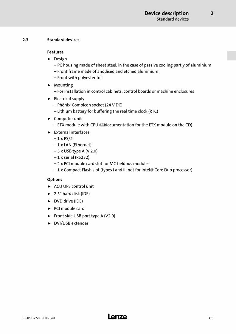
Device descriptionStandard devices
2
� 65LDCDS−ELx7xx DE/EN 4.0
2.3 Standard devices
Features
ƒ Design
– PC housing made of sheet steel, in the case of passive cooling partly of aluminium
– Front frame made of anodised and etched aluminium
– Front with polyester foil
ƒ Mounting
– For installation in control cabinets, control boards or machine enclosures
ƒ Electrical supply
– Phönix−Combicon socket (24 V DC)
– Lithium battery for buffering the real time clock (RTC)
ƒ Computer unit
– ETX module with CPU (�documentation for the ETX module on the CD)
ƒ External interfaces
– 1 x PS/2
– 1 x LAN (Ethernet)
– 3 x USB type A (V 2.0)
– 1 x serial (RS232)
– 2 x PCI module card slot for MC fieldbus modules
– 1 x Compact Flash slot (types I and II; not for Intel� Core Duo processor)
Options
ƒ ACU UPS control unit
ƒ 2.5" hard disk (IDE)
ƒ DVD drive (IDE)
ƒ PCI module card
ƒ Front side USB port type A (V2.0)
ƒ DVI/USB extender

Device descriptionStandard devices
2
� 66 LDCDS−ELx7xx DE/EN 4.0
Overview
Panel PC EL 870 / EL 1700 / EL 1700s / EL 2700 / EL 5700 / EL 9700
-F3
Fail
Power
F1
+F2
Status
� EL 870: 8" VGA touchscreenEL 1700: 10.4" VGA touchscreenEL 1700s: 10.4" SVGA touchscreenEL 2700: 12.1" SVGA touchscreenEL 5700: 15" XGA touchscreenEL 9700: 19" SXGA touchscreen
� 3 freely assignable function keys
CS57x0−026
Panel PC EL 5720
S13
S14
S11
S10
S12
S6
S7
F3F2
+ -
F4Status
Power
Fail
F1Esc EnterF11 F12F6F5 F7 F8 F9 F10
S1
S4
S2
S3
S5
S8
S9
� 15" XGA touchscreen� 12 freely assignable function keys� 14 freely assignable special keys
ELx7xx−002
Panel PC EL 1750 / EL 1750s / EL 2750 / EL 5750
Q + R
F1 F2 F5
- S T
F3 F4
@\Z
F11F10
YX
F9F8 F12
WVU
F7F6
Shift
Alpha
Bs
Space
Enter
EscDelIns
MenuAltCtrl
Home
1I
0M
4E
7A
Pg Dn
*3J K L
/,N O P
Pg Up
End
Status
Power
Fail
2
.
+6F G H
-9B C D
5
8
� EL 1750: 10.4" VGA touchscreenEL 1750s: 10.4" SVGA touchscreenEL 2750: 12.1" SVGA touchscreenEL 5750: 15" XGA touchscreen
� 12 freely assignable function keys� Numerical keypad, control keys, level switch key
alpha
CS57x0−028

Device descriptionStandard devices
2
� 67LDCDS−ELx7xx DE/EN 4.0
Panel PC EL 5770
"
(
§
&
)
=
/
$
!
>/
*
-
+
, |
54 6
87 9
1 2 3
<0
-+ Alt Strg
*+
T
F4
€
D
EWQ
XY
SA
@
F3F1 F2
R
VC
F
F5
G H J
-_
Ä
F9F8F6 F7 F10
OI P ÜUZ
Ö
;,
:Mμ .
LK
NB Space
Enter
\?ß
~
F12 EscF11
Pos 1
Einfg
Ende
Entf
Bs
Alt Gr
Fail
Status
Power
Bild
Bild
� 15" XGA touchscreen� 12 freely assignable function keys� Numerical keypad, control keys, level switch key
alpha� MF/2 keyboard
CS57x0−029

Device descriptionBaseboard
2
� 68 LDCDS−ELx7xx DE/EN 4.0
2.4 Baseboard
COM1
POWER
POWER
VGA
EPC50
FAN2
FAN3
FAN0
FAN1
CF-CARD
RESET
MO
US
E
US
B-μ
CO
NB
LIG
HT
FLAT-PANEL-LVDS
HA
RD
DIS
K/
CD
-RO
M
ACCUU
SB
_A
US
B_
B
US
B_
C
RTGEGN
CR2450
12
19
20
F1 T4A
X1 X2
X3 X4
�
�
�
�
�
�
�
CS57x0−018
� Hard disk (option)� ETX module (more detailed information can be found in the ETX module documentation
manual provided on CD)� Battery ( � 104)� ACU UPS control unit ( � 69)� Fuse ( � 105)� PCI module card slot� IDE interface

Device descriptionACU UPS control unit (option)
2
� 69LDCDS−ELx7xx DE/EN 4.0
2.5 ACU UPS control unit (option)
The optional ACU UPS Control Unit in connection with a battery pack or capacitor packexpands the Industrial PC by one UPS functionality.
The ACU UPS Control Unit is either equipped as default or can be retrofitted by the Lenzeservice.
Features of the ACU UPS Control Unit
with battery pack (ACCU−PACK) with capacitor pack (CAPS−PACK)
� Bridges a short−time mains failure or mainsfluctuations and shuts down the PC.
� Software−based configuration� � Documentation for the battery pack
� Provides a backup in the case of mains failure.� Not suitable for Windows XP.� Software−based configuration� � Documentation for the capacitor pack
POWER
EPC50
FAN2
FAN3
RESET
US
B-μ
CO
NB
LIG
HT
ACCU
CR2450
12
19
20
F1 T4A
ACU
�
USV
S
ACCU-Pack
Beforeopening,
readthe
instructionmanual.
� ��
�
CS57x0−042
� 2700 battery pack or 2701 capacitor pack (accessories)� Connection cable (included in delivery of battery pack/capacitor pack)� Port on industrial PC� ACU UPS control unit � Baseboard

Device descriptionSoftwareOperating system (accessories)
2
� 70 LDCDS−ELx7xx DE/EN 4.0
2.6 Software
2.6.1 Operating system (accessories)
The operating systems listed below can be run on the industrial PC. If ordered, they will bedelivered pre−installed on a storage medium.
Operating system Description Delivered on storage medium
Windows XP�� Multilanguage � Professional with SP2 or higher� Pre−installed languages: English, German,
French, Spanish, Portuguese (Brazil),Chinese (P.R. of China)
� Hard disk 1)
Windows XP� Embedded � Component version of Windows XP�
Professional, where the necessary softwarecomponents and drivers are factory−set.
� Pre−installed languages: English, German� For the different processor types adapted
image files are available.
� Hard disk� Compact Flash card
Windows CE� 5.0 � Real−time capable operating system withlow resource requirements
� Adapted installations are available for thevarious processor types (not for Core� Duo).
� Compact Flash−Card
1) The Industrial PC must be equipped with a hard disk.
Note!For more detailed information, please refer to the documentation for youroperating system.

Device descriptionSoftware
Fan monitoring with "Smart Cool" and "FAN Service" (option)
2
� 71LDCDS−ELx7xx DE/EN 4.0
2.6.2 Fan monitoring with "Smart Cool" and "FAN Service" (option)
"Smart Cool"
Forced−ventilated industrial PCs are always provided with a temperature monitoringsystem which is controlled via the "Smart Cool" software.
A thermal sensor measures the temperature inside the housing of the industrial PC. Whena preset temperature is exceeded, the fans of the industrial PC are switched on by "SmartCool". When the temperature has dropped again, "Smart Cool" switches off the fans.
A default setting depending on the installed PC components determines which fans in theindustrial PC are to be controlled by the software and at which temperature the fans areto be switched on.
The software starts automatically together with the operating system and runs in thebackground.
You can open the user interface of "Smart Cool" via the identically−named entry in thesystem control. The user interface provides option boxes for selecting one of the followingstates:
"Smart Cool" state: Temperature monitoring is active and operates as described above(default setting).
"FAN on" state: All fans of the industrial PC are running continuously.
The assigned state remains selected even after a restart.
"FAN Service"
The "FAN Service" is installed together with "Smart Cool". It monitors the fans of theIndustrial PC and reports (Windows) or logs (log file) the following system states:
ƒ Fan failure
ƒ Faulty or empty buffer battery
The "FAN Service" runs in the background and has no user interface.
The "LogFanService.txt" log file can be found under ...
ƒ Windows XP (Embedded) in the "Smart Cool" program folder (e.g. "x:\Programs\Lenze\SmartCool\)
ƒ Windows CE in the "x:\Storage\DeviceScanner\" folder
Note!In order that the log files will not get too long, their data are moved to the"LogFanService.bak" file as soon as the data size exceeds 100 kB.

Device descriptionSoftwareFan monitoring with "Smart Cool" and "FAN Service" (option)
2
� 72 LDCDS−ELx7xx DE/EN 4.0
Installation notes
If you have purchased the operating system pre−installed on a storage medium from Lenze,the fan monitoring software has already been installed.
In all other cases, you can find the software on the driver CD of your industrial PC. Theinstallation procedure differs, depending on the operating system used:
Windows XP: Start the setup program on the driver CD and follow the instructions of thesetup wizard. When the installation has been completed successfully, the industrial PC hasto be restarted.
Windows CE: Complete the following lines in the autostart file of Windows CE:
open "wceload.exe" "/noaskdest/noui/nouninstall \Storage\DeviceScanner\SmartCoolCab.cab"\Storage\DeviceScanner\FANServiceCE.exe
When the industrial PC restarts, the self−extracting CAB file is executed.

Technical dataGeneral data and operating conditions
3
� 73LDCDS−ELx7xx DE/EN 4.0
3 Technical data
3.1 General data and operating conditions
Conformity and approval
Conformity
CE EN 61000 6−4EN 61000 6−2
EMC Directive Class A, industrial premises
Approbation
UL UL 508CSA C22.2
Programmable Controllers (File−No. E236341)
Protection of persons and equipment
Safety VDE0805 (EN60950),VDE0870, UL
Enclosure IP65 (front) / IP20 (back)
Class of protection 3
Mounting conditions
Place of installation Control cabinet
Mounting position Connections at the bottom
Ambient conditions
Climatic
Storage −10 ... +60 °C
Transport −10 ... +60 °C
Operation Equipment−dependent (� 74)
Relative humidity 10 ... 90 %, no condensation
Site altitude < 3000 m amsl
Chemical resistance
Decor filmDIN 42115
Housing
Mechanical load capacity
Decor filmDIN 42115 max. 100 N
Switching element

Technical dataGeneral data and operating conditions
3
� 74 LDCDS−ELx7xx DE/EN 4.0
Note!The failure probability of an electronic component increases with the ambienttemperature to which the component is subjected. Regarding theserviceability and reliability, particular attention should be paid to the coolingof the device. For every application, you should take care to keep the heatingof the device as low as possible.
ƒ We recommend to use forced−ventilated systems with "Smart Cool" fancontrol to ensure sufficient heat dissipation.
The fan control monitors the internal temperature of the device and thefunctioning of the fan. When a preset maximum temperature is exceeded,the control system switches on the fan. When the fan speed falls below aminimum speed, the control system signals a fault.
ƒ Systems with passive cooling via heatsinks should only be used if it isguaranteed that there is always sufficient convection (e.g. by means ofexternal fan modules in the control cabinets or the installation of the devicein air−conditioned areas).
Permissible ambient temperatures for fanless systems
Standard device � Up to 1 GBRAM
� With CF card� 20−GB hard
disk forexpandedtemperaturerange
� 40−GB harddisk
� 40−GB harddisk forcontinuousoperation(24/7) *
� DVD drive(read only)
� DVD drive(read andwrite)
Processor [°C]
AMD GeodeLX800 / 500 MHz
0 ... 455 ... 40
5 ... 455 ... 45 5 ... 40
Mobile Intel�Celeron M600 MHz
Mobile Intel�Celeron M 1 GHz
0 ... 40 5 ... 40
* We recommend to replace the hard disk after 30,000 operating hours or after 5 years.

Technical dataGeneral data and operating conditions
3
� 75LDCDS−ELx7xx DE/EN 4.0
Permissible ambient temperatures for systems with "Smart Cool" cooling
Standard device � Up to 1 GBRAM
� With CF card� 20−GB hard
disk forexpandedtemperaturerange
� 40−GB harddisk
� 40−GB harddisk forcontinuousoperation(24/7) *
� DVD drive(read only)
� DVD drive(read andwrite)
Processor [°C]
AMD GeodeLX800 / 500 MHz
0 ... 50
5 ... 45 5 ... 45 5 ... 45
5 ... 40
Mobile Intel�Celeron M600 MHz
Mobile Intel�Celeron M 1 GHz
Mobile Intel�Celeron M1.5 GHz
Mobile Intel�Celeron M1.8 GHz
0 ... 45Intel� Core�Duo 1.66 GHz atmax. 50 % CPUutilisation 2)
Intel� Core�Duo 1.66 GHz atmax. 100 % CPUutilisation 2)
0 ... 40 5 ... 40 5 ... 40 5 ... 40
1* We recommend to replace the hard disk after 30,000 operating hours or after 5 years.2) The CPU utilisation can be determined via the Windows task manager (register "System performance")

Technical dataElectrical data
3
� 76 LDCDS−ELx7xx DE/EN 4.0
3.2 Electrical data
Supply
Device Fuse Buffer battery
Voltage Current at 24 V 1) Type Type Service life
[V DC] [A] [years]
EL 870
24 (+18 ... 30) 2)
1.3
� 105 � 104 > 6 (25 °C)
EL 1700
EL 1700s
EL 1750
EL 1750s
EL 27001.2
EL 2750
EL 5700
1.4EL 5720
EL 5750
EL 5770
EL 9700 2.1
1) Measured with Celeron M600 CPU and CF card
2) With ACU UPS Control Unit DC +20 ... 30 V
Screen
Visible size Aspect ratio Resolution Brightness Contrast MTBF
[inches] [pixels] [cd/m2] [h]
EL 870 8
4:3
640 x 480
320 1 : 250 50,000
EL 1700EL 1750
10.4
400 1 : 300 40,000
EL 1700sEL 1750s
800 x 600
400 1 : 500
50,000EL 2700EL 2750
12.1 300 1 : 200
EL 5700EL 5720EL 5750EL 5770
15 1024 x 768 250 1 : 550 40,000
EL 9700 19 1280 x 1024 300 1 : 700 50,000

Technical dataElectrical data
3
� 77LDCDS−ELx7xx DE/EN 4.0
Interfaces
Type Connection
COM RS232 Sub−D plug, 9−pole
LAN Ethernet 10/100 Mbit RJ45 socket
USB 2.0 Type A socket
PS/2 Standard PS/2 socket, 6−pole
PCI PCI module card slot MC fieldbus modules
Exchangeable diskstorage
Compact Flash Compact Flash slot (types I and II; not for Intel� Core Duoprocessor)
Note!The technical data of the ETX module can be obtained from the ETX moduledocumentation on the manual CD.
Type Operating voltage Max. current Charging current in operatingrange
[V DC] [mA] [mA]
At 5 V At 12 V
ACU UPS 12 / 5 10 10 ... 600 1) Approx. 250
1) Subject to charging

Technical dataMechanical data
3
� 78 LDCDS−ELx7xx DE/EN 4.0
3.3 Mechanical data
Designs and weights
Front frame / housing Touchscreen Mass *)
[kg]
EL 870
Aluminium/sheet steel Polyester foil
4.0
EL 1700 4.6
EL 1700s 4.6
EL 1750 5.0
EL 1750s 5.0
EL 2700 5.8
EL 2750 6.0
EL 5700 6.6
EL 5720 6.8
EL 5750 6.8
EL 5770 7.6
EL 9700 10.6
*) Without optional accessories (hard disk, DVD drive, etc.)

Technical dataMechanical data
3
� 79LDCDS−ELx7xx DE/EN 4.0
dis
c
CD/DVD
a
b
6e27.5
65
CD/DVD
ELx7xx−003
All dimensions in millimetres.
Dimensions
a b e
[mm]
EL 870 265 188
99
EL 1700325
240EL 1700s
EL 1750365
EL 1750s
EL 2700 390 300
EL 2750 425 310
EL 5700 450 325
EL 5720
483310 (7 U)
EL 5750
EL 5770 399 (9 U)
EL 9700 490 400 109

Mechanical installationImportant notes
4
� 80 LDCDS−ELx7xx DE/EN 4.0
4 Mechanical installation
4.1 Important notes
The installation must be carried out by qualified, skilled personnel familiar with theapplicable national standards.
� Stop!Sensitive front frame gasket
During mounting, the gasket of the front frame is exposed and can bedamaged.
Possible consequences:
ƒ The degree of protection provided by the enclosure mentioned in thetechnical data is not attained.
Protective measures:
ƒ Handle the gasket with care during mounting.
ƒ Protect the gasket against ultraviolet rays.
ƒ Each time before you mount the device, check whether the gasket is intact.
� Stop!Sensitive touchscreen surface
The touchscreen foil is very sensitive to external forces and can be damaged byimproper handling.
Possible consequences:
ƒ The touchscreen foil becomes damaged, scratched or dull.
Protective measures:
ƒ Avoid contact of the touchscreen foil with pointed or hard objects.
ƒ Always use a touch pen or your fingers to operate the touchscreen. Neveruse objects such as ballpoint pens, pencils, etc.
ƒ When removing dirt and fingerprints, observe the notes given in the chapter"Cleaning" (� 99).
Note!When selecting the place where the PC is to be installed, pay attention to anergonomic positioning of the screen and to the incidence of light which mightcause reflections on the screen.

Mechanical installationMounting cutout
4
� 81LDCDS−ELx7xx DE/EN 4.0
4.2 Mounting cutout
��
a1
a2
� 5
�
b1
b2
b3
b5
b4
D
ELx7xx−004
� Mounting cutout� Outline of front panel� Control board
All dimensions in millimetres.
Dimensions
a1 a2 b1 b2 b3 b4 b5 D
[mm]
EL 870 246.0 − 188.0 − − − − −
EL 1700305.0 − 228.0 − − − − −
EL 1700s
EL 1750343.0 − 228.0 − − − − −
EL 1750s
EL 2700 340.0 351.0 228.0 122.0 122.0 0.0 −
6 x �5.5
EL 2750 375.0 386.0 228.0 122.0 122.0 0.0 −
EL 5700 400.0 411.0 313.0 134.5 134.5 0.0 −
EL 5720452.0 462.4 299.0 104.9 104.6 15.7 −
EL 5750
EL 5770 452.0 462.4 388.2 149.3 149.3 15.9 −
EL 9700 438.0 451.0 386.0 172.0 172.0 60.0 60.0 8 x �4.5

Mechanical installationMounting stepsPanel PC EL 870 / EL 1700(s) / EL 1750(s)
4
� 82 LDCDS−ELx7xx DE/EN 4.0
4.3 Mounting steps
4.3.1 Panel PC EL 870 / EL 1700(s) / EL 1750(s)
Proceed as follows for the mounting:
1. Cut the mounting cutout into the control board (� 81).
2. Check that the gasket under the front panel is located correctly.
3. Place the device in the mounting cutout and secure it against falling−down with onehand.
4. Fit all screw clamp fixings as explained below:
� �
�
ELx7xx−011
– Insert the screw clamp fixing into the slot in the housing of the device (see abovefigure).
– Press the screw clamp fixing downwards, tilt it towards the housing and checkthat it has firmly snapped into place.
– Tighten the screw clamp fixing hand−tight with a screwdriver.
5. Check that the device is securely located in the mounting cutout and that the frontpanel gasket is located correctly.
– If necessary, realign the device/gasket.
– If the gasket is not located correctly, protection class IP65 is not achieved on thefront of the device!

Mechanical installationMounting steps
Panel PC EL 2700 / EL 2750 / EL 5700 / EL 5720 / EL 5750 / EL 5770 / EL 9700
4
� 83LDCDS−ELx7xx DE/EN 4.0
4.3.2 Panel PC EL 2700 / EL 2750 / EL 5700 / EL 5720 / EL 5750 / EL 5770 / EL 9700
Note!The EL 5720, EL 5750 and EL 5770 types can be installed in any control boardand in 19" mounting racks to DIN 41494.
Control board mounting
Proceed as follows for the mounting:
1. Prepare the control board by cutting the mounting cutout and drilling the mountingholes into it (� 81).
2. Check that the gasket under the front panel is located correctly.
3. Place the device in the mounting cutout, secure it by hand against falling down andscrew the nuts and washers onto the threaded bolts.
4. Fit all screw clamp fixings as explained below:
� �
�
ELx7xx−012
– Insert the screw clamp fixing into the slot in the housing of the device (see abovefigure).
– Press the screw clamp fixing downwards, tilt it towards the housing and checkthat it has firmly snapped into place.
– Tighten the screw clamp fixing hand−tight with a screwdriver.
5. Check that the device is securely located in the mounting cutout and that the frontpanel gasket is located correctly.
– If necessary, realign the device/gasket.
– If the gasket is not located correctly, protection class IP65 is not achieved on thefront of the device!

Mechanical installationMounting stepsPanel PC EL 2700 / EL 2750 / EL 5700 / EL 5720 / EL 5750 / EL 5770 / EL 9700
4
� 84 LDCDS−ELx7xx DE/EN 4.0
Installation in 19" mounting racks (EL 5720, EL 5750 and EL 5770 only)
Proceed as follows for the mounting:
1. Remove the set screws from the back of the front frame.
2. Drill through the blind holes at the back of the front frame using a 6.5 mm drill.
3. Place the device in the 19" mounting rack and fasten it with screws.

Electrical installationImportant notes
5
� 85LDCDS−ELx7xx DE/EN 4.0
5 Electrical installation
5.1 Important notes
The installation must be carried out by qualified, skilled personnel familiar with theapplicable national standards.
� Stop!Sensitive front frame gasket
During mounting, the gasket of the front frame is exposed and can bedamaged.
Possible consequences:
ƒ The degree of protection provided by the enclosure mentioned in thetechnical data is not attained.
Protective measures:
ƒ Handle the gasket with care during mounting.
ƒ Protect the gasket against ultraviolet rays.
ƒ Each time before you mount the device, check whether the gasket is intact.
� Stop!Sensitive touchscreen surface
The touchscreen foil is very sensitive to external forces and can be damaged byimproper handling.
Possible consequences:
ƒ The touchscreen foil becomes damaged, scratched or dull.
Protective measures:
ƒ Avoid contact of the touchscreen foil with pointed or hard objects.
ƒ Always use a touch pen or your fingers to operate the touchscreen. Neveruse objects such as ballpoint pens, pencils, etc.
ƒ When removing dirt and fingerprints, observe the notes given in the chapter"Cleaning" (� 99).

Electrical installationImportant notes
5
� 86 LDCDS−ELx7xx DE/EN 4.0
� Stop!Short circuit and static discharge
The device contains components which are endangered in the case of shortcircuit or static discharge.
Possible consequences:
ƒ The device or parts of it are destroyed.
Protective measures:
ƒ When working on the device, always switch off the voltage supply (mainsand a possibly mounted UPS). This particularly applies to the following:– Before opening the housing.– Before connecting / removing connectors.– Before plugging in / plugging out modules.
ƒ All persons handling printed circuit boards have to take account of ESDmeasures.
ƒ Contacts of connectors may not be touched.
ƒ Printed circuit boards may be touched only at places free from electricalcontacts and may be placed only on appropriate materials (e.g. on ESDpackaging or conductive foam material).
ƒ Printed circuit boards may only be transported and stored in ESD packaging.

Electrical installationConnecting the supply voltage
Mains connection (X101)
5
� 87LDCDS−ELx7xx DE/EN 4.0
5.2 Connecting the supply voltage
5.2.1 Mains connection (X101)
� Stop!
No device protection against excessive input voltage
The voltage input is not fused internally.
Possible consequences:
ƒ The device can be destroyed when the input voltage is too high.
Protective measures:
ƒ Observe the max. permissible input voltage.
ƒ Professionally fuse the device on the input side against voltage fluctuationsand voltage peaks.
Note!The IPC boots up as soon as the supply voltage is applied.
After the operating system has been shut down, the IPC switches offautomatically. For restarting, the supply voltage has to be disconnected for ashort time.
L1N
PE
L1 N
0V +24
~ =0 V PE +24 V
�
�
F
S
Elx7xx−006
� Panel PC� Power supply unit
Description Connection type Cable type
0V U
24 V DC supply connection3−pole Phoenix Combicon
socket
Cable (max. conductorcross−section: 2.5 mm2) with
Phoenix Combicon plug,MSTB 2.5 / 3−STF−5.08
IPC001
PE connection M4 threaded boltSeparate earthing conductor
(min. 2.5 mm2) with ringcable lug
IPC001

Electrical installationConnecting the supply voltageUPS−PACK connection (X102)
5
� 88 LDCDS−ELx7xx DE/EN 4.0
5.2.2 UPS−PACK connection (X102)
Description Connection type Cable type
Connection of battery pack(� LDCDS−2700) or capacitorpack (� LDCDS−2701)
2−pin socket
EPC5x−ACU (included in delivery ofbattery/capacitor pack;
length 2.5 m; extension cableavailable)
IPC001

Electrical installationConnecting external devices
PS/2 interface (X108)
5
� 89LDCDS−ELx7xx DE/EN 4.0
5.3 Connecting external devices
5.3.1 PS/2 interface (X108)
Description Connection type Cable type
PS/2 connection 6−pin, mini DIN
PS/2 mouse(a keyboard and a mouse can
be connected via a PS/2 Ycable)
IPC001
5.3.2 Serial interface (X103)
Description Connection type Cable type
6
1
RS232 connectionPin 1: DCDPin 2: RxDPin 3: TxDPin 4: DTRPin 5: GNDPin 6: DSRPin 7: RTSPin 8: CTSPin 9: RI
9−pin Sub−D connectorControl cable, shielded, with
9−pin Sub−D socket
IPC001
5.3.3 Ethernet interface (X107)
Description Connection type Cable type
Ethernet connection RJ45 socket
CAT5 S/UTP or CAT5e S/FTP(recommended) networkcable, max. cable length
100 mIPC001
5.3.4 USB interface (X104, X105, X106)
Description Connection type Cable type
Connection for USB host USB−A socket USB cable with USB−A plug
IPC001
5.3.5 PCI module card interface
Description Connection type Cable type
Module card Socket connector MC fieldbus modules
EL100−013

Electrical installationConnecting external devicesUSB interface on the front face (option)
5
� 90 LDCDS−ELx7xx DE/EN 4.0
5.3.6 USB interface on the front face (option)
Description Connection type Cable type
USB host connection withIP65 cover cap
USB−A socket USB cable with USB−A plug
EL100−013
Note!If you use USB interfaces routed to outside, the data integrity cannot beguaranteed. On the driver CD, you find the "FM Tool" software which can beused to deactivate the front USB interface if it is not needed.
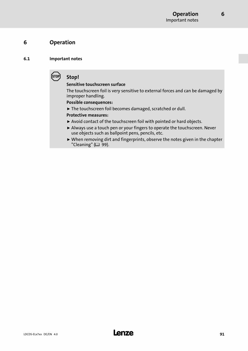
OperationImportant notes
6
� 91LDCDS−ELx7xx DE/EN 4.0
6 Operation
6.1 Important notes
� Stop!Sensitive touchscreen surface
The touchscreen foil is very sensitive to external forces and can be damaged byimproper handling.
Possible consequences:
ƒ The touchscreen foil becomes damaged, scratched or dull.
Protective measures:
ƒ Avoid contact of the touchscreen foil with pointed or hard objects.
ƒ Always use a touch pen or your fingers to operate the touchscreen. Neveruse objects such as ballpoint pens, pencils, etc.
ƒ When removing dirt and fingerprints, observe the notes given in the chapter"Cleaning" (� 99).

OperationControls and displaysPanel PC EL 870 / EL 1700 / EL 1700s / EL 2700 / EL 5700 / EL 9700
6
� 92 LDCDS−ELx7xx DE/EN 4.0
6.2 Controls and displays
6.2.1 Panel PC EL 870 / EL 1700 / EL 1700s / EL 2700 / EL 5700 / EL 9700
-F3
Fail
Power
F1
+F2
Status �
�
�
��ELx7xx007
Pos. Designation Function
Standard mode Service mode
Switch on mode: Press "�" for 5 s
Switch off mode: Press "�" or wait for 35 s
� Display Application−dependent
� Status LEDs Power (green):� Is ON when the supply voltage is present.Fail (red):� Is On when a power supply failure has occurred.� Is blinking when the screen signal is missing.Status (yellow):� Indicates access to a storage medium.
� Function keys F1 ... F3: Send key code for Shift−Fx Tool: Application−dependent+: Increase screen brightness−: Reduce screen brightness
� Reset button Reset PC (restart)
� Status LEDs Error (red):� Is lit if a power supply failure has occurred.� Is blinking when the screen signal is missing.HD (yellow):� Indicates access to a storage medium.Power (green):� Is lit when the supply voltage is present.� Flashes (−−−
−−−−
−) in the case of a hardware error.� Is blinking (−−
−−−
−) when the ACU UPS (optional) is being charged.� Is blinking (−−
−−−−
−−) when there is a supply voltage failure and the device is beingsupplied by the ACU UPS.
� Is blinking (−−−−) when the supply voltage of the ACU UPS is too low (e.g.
rechargeable battery is empty or missing).� Blinks 4 x per second if the ACCU−PACK causes a short circuit or if the CAPS−PACK
is completely discharged.

OperationControls and displays
Panel PC EL 5720
6
� 93LDCDS−ELx7xx DE/EN 4.0
6.2.2 Panel PC EL 5720
�
�
�
��
S13
S14
S11
S10
S12
S6
S7
F3F2
+ -
F4Status
Power
Fail
F1Esc EnterF11 F12F6F5 F7 F8 F9 F10
S1
S4
S2
S3
S5
S8
S9
�
ELx7xx010
Pos. Designation Function
Standard mode Service mode
Switch on mode: Press "�" for 5 s
Switch off mode: Press "�" or wait for 35 s
� Display Application−dependent
� Status LEDs Power (green):� Is ON when the supply voltage is present.Fail (red):� Is On when a power supply failure has occurred.� Is blinking when the screen signal is missing.Status (yellow):� Indicates access to a storage medium.
� Function keys F1 ... F12: Send key code for Fx Tool: Application−dependent+: Increase screen brightness−: Reduce screen brightness
� Reset button Reset PC (restart)
� Status LEDs Error (red):� Is lit if a power supply failure has occurred.� Is blinking when the screen signal is missing.HD (yellow):� Indicates access to a storage medium.Power (green):� Is lit when the supply voltage is present.� Flashes (−−−
−−−−
−) in the case of a hardware error.� Is blinking (−−
−−−
−) when the ACU UPS (optional) is being charged.� Is blinking (−−
−−−−
−−) when there is a supply voltage failure and the device is beingsupplied by the ACU UPS.
� Is blinking (−−−−) when the supply voltage of the ACU UPS is too low (e.g.
rechargeable battery is empty or missing).� Blinks 4 x per second if the ACCU−PACK causes a short circuit or if the CAPS−PACK
is completely discharged.
� Special keys Left key blockS1 ... S7: Send key code for Shift−F1 ... Shift−F7Right key blockS8 ... S14: Send key code for CTRL−F1 ... CTRL−F7

OperationControls and displaysPanel PC EL 1750 / EL 1750s / EL 2750 / EL 5750
6
� 94 LDCDS−ELx7xx DE/EN 4.0
6.2.3 Panel PC EL 1750 / EL 1750s / EL 2750 / EL 5750
Q + R
F1 F2 F5
- S T
F3 F4
@\Z
F11F10
YX
F9F8 F12
WVU
F7F6
Shift
Alpha
Bs
Space
Enter
EscDelIns
MenuAltCtrl
Home
1I
0M
4E
7A
Pg Dn
*3J K L
/,N O P
Pg Up
End
Status
Power
Fail
2
.
+6F G H
-9B C D
5
8
�
�
�
�
�
��ELx7xx008

OperationControls and displays
Panel PC EL 1750 / EL 1750s / EL 2750 / EL 5750
6
� 95LDCDS−ELx7xx DE/EN 4.0
Pos. Designation Function
Standard mode Alpha mode Service mode
Switch on mode: Press "alpha key" (LED is on) Press "menu key"
Switch off mode: Press "alpha key" (LED is off) Press "menu key" or wait for35 s
� Display Application−dependent
� Status LEDs Power (green):� Is ON when the supply voltage is present.Fail (red):� Is ON when a power supply failure has occurred; is blinking when the screen signal is
missing.Status (yellow):� Indicates access to a storage medium.
� Function keys F1 ... F12: Send key code forShift−Fx
F1 ... F12: Send key codes for"Q" ... "@"
Tool: Application−dependent+: Increase screen brightness−: Reduce screen brightness
� Reset button Reset PC (restart)
� Status LEDs Error (red):� Is lit if a power supply failure has occurred;� Is blinking when the screen signal is missing.HD (yellow):� Indicates access to a storage medium.Power (green):� Is lit when the supply voltage is present.� Flashes (−−−
−−−−
−) in the case of a hardware error.� Is blinking (−−
−−−
−) when the ACU UPS (optional) is being charged.� Is blinking (−−
−−−−
−−) when there is a supply voltage failure and the device is being suppliedby the ACU UPS.
� Is blinking (−−−−) when the supply voltage of the ACU UPS is too low (e.g. rechargeable
battery is empty or missing).� Blinks 4 x per second if the ACCU−PACK causes a short circuit or if the CAPS−PACK is
completely discharged.
� Numerickeypad
Send key codes for "0" ... "9"and calculation operators
Send key codes for "A" ... "P" Functionality same as instandard/alpha mode
� Cursor keys Without "Shift" key: Move cursor/marker in steps and settabWith "Shift" key: Move cursor/marker to the beginning/endor page by page
Functionality same as instandard/alpha mode
� Control keys Standard functions of an MF2 keyboard(For "alpha" and �/� see "Switching on/off of mode)
Functionality same as instandard/alpha mode

OperationControls and displaysPanel PC EL 5770
6
� 96 LDCDS−ELx7xx DE/EN 4.0
6.2.4 Panel PC EL 5770
�
"
(
§
&
)
=
/
$
!
>/
*
-
+
, |
54 6
87 9
1 2 3
<0
-+ Alt Strg
*+
T
F4
€
D
EWQ
XY
SA
@
F3F1 F2
R
VC
F
F5
G H J
-_
Ä
F9F8F6 F7 F10
OI P ÜUZ
Ö
;,
:Mμ .
LK
NB Space
Enter
\?ß
~
F12 EscF11
Pos 1
Einfg
Ende
Entf
Bs
Alt Gr
Fail
Status
Power
Bild
Bild
�
��
�
�
��ELx7xx009

OperationControls and displays
Panel PC EL 5770
6
� 97LDCDS−ELx7xx DE/EN 4.0
Pos. Designation Function
Standard mode Alpha mode Service mode
Switch on mode: Press "alpha key" (LED is on) Press "menu key"
Switch off mode: Press "alpha key" (LED is off) Press "menu key" or wait for35 s
� Display Application−dependent
� Status LEDs Power (green):� Is ON when the supply voltage is present.Fail (red):� Is ON when a power supply failure has occurred; is blinking when the screen signal is
missing.Status (yellow):� Indicates access to a storage medium.
� Function keys F1 ... F12: Send key code forShift−Fx
F1 ... F12: Send key codes for"Q" ... "@"
Tool: Application−dependent+: Increase screen brightness−: Reduce screen brightness
� Reset button Reset PC (restart)
� Status LEDs Error (red):� Is lit if a power supply failure has occurred;� Is blinking when the screen signal is missing.HD (yellow):� Indicates access to a storage medium.Power (green):� Is lit when the supply voltage is present.� Flashes (−−−
−−−−
−) in the case of a hardware error.� Is blinking (−−
−−−
−) when the ACU UPS (optional) is being charged.� Is blinking (−−
−−−−
−−) when there is a supply voltage failure and the device is being suppliedby the ACU UPS.
� Is blinking (−−−−) when the supply voltage of the ACU UPS is too low (e.g. rechargeable
battery is empty or missing).� Blinks 4 x per second if the ACCU−PACK causes a short circuit or if the CAPS−PACK is
completely discharged.
� Numerickeypad
Send key codes for "0" ... "9"and calculation operators
Send key codes for "A" ... "P" Functionality same as instandard/alpha mode
� Cursor keys Without "Shift" key: Move cursor/marker in steps and settabWith "Shift" key: Move cursor/marker to the beginning/endor page by page
Functionality same as instandard/alpha mode
� Control keys Standard functions of an MF2 keyboard(For "alpha" and �/� see "Switching on/off of mode)
Functionality same as instandard/alpha mode
� Control keys Standard functions of an MF2 keyboard Without function

Maintenance7
� 98 LDCDS−ELx7xx DE/EN 4.0
7 Maintenance
� Stop!Short circuit and static discharge
The device contains components which are endangered in the case of shortcircuit or static discharge.
Possible consequences:
ƒ The device or parts of it are destroyed.
Protective measures:
ƒ When working on the device, always switch off the voltage supply (mainsand a possibly mounted UPS). This particularly applies to the following:– Before opening the housing.– Before connecting / removing connectors.– Before plugging in / plugging out modules.
ƒ All persons handling printed circuit boards have to take account of ESDmeasures.
ƒ Contacts of connectors may not be touched.
ƒ Printed circuit boards may be touched only at places free from electricalcontacts and may be placed only on appropriate materials (e.g. on ESDpackaging or conductive foam material).
ƒ Printed circuit boards may only be transported and stored in ESD packaging.

MaintenanceRegular checks
7
� 99LDCDS−ELx7xx DE/EN 4.0
7.1 Regular checks
The device is free of maintenance. Nevertheless, visual inspections should be carried outat regular intervals which must not be too long, depending on the ambient conditions.
Please check the following:
ƒ Does the environment of the device meet the operating conditions specified in theTechnical data?
ƒ Is the heat dissipation of the device not impeded by dust or dirt?
ƒ Are the mechanical and electrical connections o.k.?
7.2 Cleaning
� Stop!Sensitive surfaces and components
The device can be damaged if it is not appropriately cleaned.
Possible consequences:
ƒ The housing and in particular the screen gets scratched or dull if you usealcoholic, solvent−containing or scouring cleaning agents.
ƒ The electrical components are damaged if humidity enters the housing.
Protective measures:
ƒ Switch off the device before cleaning.
ƒ Only use an approved TFT screen cleaner as cleaning agent for the screen,and for the housing a standard household cleaning agent.
ƒ First spray or drizzle the cleaning agent on a clean, soft cloth and then wipeover the screen or the housing surface.

MaintenanceRepairRemove the PC housing
7
� 100 LDCDS−ELx7xx DE/EN 4.0
7.3 Repair
7.3.1 Remove the PC housing
With DVD drive
dis
c
� �
�
�
�
��
�
dis
c
��
a b
c�
�
ELx7xx−013
Proceed as follows when a DVD drive is mounted:
1. Remove the mains cable � (� 87)
2. Remove the DVD drive �:
– Loosen the fixing screw �.
– Push the DVD drive to the right.
– Carefully take off the DVD drive.
– Remove the ribbon cable �.
3. Only for fanless devices: Loosen the three screws �.
4. Remove the housing �:
– Loosen the three screws �.
– Carefully pull the housing � off towards the front while passing the ribbon cable �through the housing aperture.

MaintenanceRepair
Remove the PC housing
7
� 101LDCDS−ELx7xx DE/EN 4.0
Without DVD drive
�
�
�
��
�
�
�
ELx7xx−015
Proceed as follows when no DVD drive is mounted:
1. Remove the mains cable � (� 87).
2. Only for fanless devices: Loosen the three screws �.
3. Remove the housing �:
– Loosen the four screws �.
– Carefully pull the housing � off towards the front.

MaintenanceRepairMount the PC housing
7
� 102 LDCDS−ELx7xx DE/EN 4.0
7.3.2 Mount the PC housing
With DVD drive
�
��
�
�
�
�
dis
c
�
�
c
ba
�
dis
c
�
�
ELx7xx−014
Proceed as follows when a DVD drive is mounted:
1. Mount the housing �:
– Pass the ribbon cable � through the housing aperture and carefully place thehousing � on the housing base.
– Screw in the three screws �.
2. Only for fanless devices: Screw in the three screws � and tighten them.
The internal heatsink must be firmly connected with the housing. Otherwise, the heatdissipation will not suffice, and the device might be damaged.
3. Mount the DVD drive �:
– Plug on the ribbon cable �.
– Carefully place the DVD drive � on the slots in the housing.
– Push the DVD drive � to the left until it snaps into place.
– Screw in the fixing screw �.
4. Plug on the mains cable � (� 87).

MaintenanceRepair
Mount the PC housing
7
� 103LDCDS−ELx7xx DE/EN 4.0
Without DVD drive
�
�
�
��
�
�
�
ELx7xx−016
1. Mount the housing �:
– Carefully place the housing � on the housing base.
– Screw in the four screws �.
2. Only for fanless devices: Screw in the three screws � and tighten them.
The internal heatsink must be firmly connected with the housing. Otherwise, the heatdissipation will not suffice, and the device might be damaged.
3. Plug on the mains cable � (� 87).

MaintenanceRepairBattery change
7
� 104 LDCDS−ELx7xx DE/EN 4.0
7.3.3 Battery change
Danger!Danger of fire and explosion
On the baseboard (� 68) there is a battery for buffering the clock (RTC) whenthe device has been switched off.
Possible consequences:
ƒ The use of other batteries than the approved ones or improper handling canresult in a fire, explosion, or environmental damage.
Protective measures:
ƒ The battery may only be replaced by an approved battery type according tothe following list.
ƒ The battery may not be recharged or opened. Furthermore it may not bethrown into a fire or be heated above 100 °C (212 °F).
ƒ Do not dispose of used batteries in the household waste. Dispose of themaccording to the local regulations.
Approved types:
ƒ Matsushita CR2450
ƒ Renata CR2450N
ƒ Sony Corp. CR2450B1A
ƒ Toshiba CR2450
ƒ Varta Microbattery GmbH CR2450
POWER
FAN2
FAN3
CF-CARD
RESET
US
B-μ
CO
NB
LIG
HT
ACCU
CR2450
12
19
20
F1 T4A
�
�
ELx7xx−017
How to proceed:
1. Remove the PC housing (� 100).
2. Remove the old battery � from the support.
3. Insert a new battery � into the support so that the positive pole is at the top.
4. Mount the PC housing (� 102).

MaintenanceRepair
Fuse change
7
� 105LDCDS−ELx7xx DE/EN 4.0
7.3.4 Fuse change
Danger!Hidden damage possible after blowing of fuses
The baseboard (� 68) is protected by a fuse which will be damaged if thevoltage applied is too high.
Possible consequences:
ƒ The device can be damaged if a non−approved fuse is installed.
ƒ In the event of a blowing fuse, hidden damage on the device cannot be ruledout. Faultless operation can no longer be guaranteed.
Protective measures:
ƒ The fuse may only be replaced by an approved type.
ƒ In the case of safety−critical applications the device has to be checked byLenze after the blowing of fuses.
Approved types:
ƒ Littelfuse, series 154, 4 A
POWER
FAN2
FAN3
CF-CARD
RESET
US
B-μ
CO
NB
LIG
HT
ACCU
CR2450
12
19
20
F1 T4A
�
ELx7xx−018
Proceed as follows:
1. Remove the mains cable (� 87).
2. Open the housing (� 100).
3. Remove the old fuse � from the holder.
4. Insert a new fuse � into the holder.
5. Close the housing (� 87).
6. Plug in the mains cable (� 100).

Index8
�106 LDCDS−ELx7xx DE/EN 4.0
8 Index
AACU UPS control unit, 69
Ambient conditions
− climatic, 73
− site altitude, 73
− Chemical resistance, 73
Application as directed, 64
Approbation, 73
BBack−up battery, change, 104
Baseboard, 68
Battery, change, 104
Battery pack, 69
CCapacitor pack, 69
Chemical resistance, 73
Class of protection, 73
COM connection, 89
Conformity, 73
Connecting the supply voltage, 87
Connections, 77
Controls, 92
− EL 1700(s), 92
− EL 1750(s), 94
− EL 2700, 92
− EL 2750, 94
− EL 5700, 92
− EL 5720, 93
− EL 5750, 94
− EL 5770, 96
− EL 870, 92
− EL 9700, 92
DDanger
− Short circuit, 86 , 98
− Static discharge, 86 , 98
Definition of notes used, 61
Design, device, 78
Device
− Controls and displaysEL 1700(s), 92 EL 1750(s), 94 EL 2700, 92 EL 5700, 92 , 94 EL 5720, 93 EL 5770, 96 EL 870, 92 EL 9700, 92 , 94
− Design, 78
− Overview, 56
− radio interference, 62
− waste disposal, 62
− Weight, 78
Display, 76
Displays, 92
− EL 1700(s), 92
− EL 1750(s), 94
− EL 2700, 92
− EL 2750, 94
− EL 5720, 93
− EL 5770, 96
− EL 870, 92
− EL 9700, 92 , 94
EElectrical data, 76
Electrical installation, 85
− COM, 89
− Connecting the supply voltage, 87
− Ethernet, 89
− LAN, 89
− Mains, 87
− PCI, 89
− PS/2, 89
− RS232, 89
− UPS, 88
− USBFront face, 90 Internal, 89
Enclosure, 73
Ergonomics, 62
Ethernet connection, 89
FFan monitoring, 71
FAN Service, 71
Features, 65
Fehlerfall, Verhalten, 62
Fuse, change, 105
IIdentification, 56
Installation, electrical, 85
Installation, mechanical, 80
Interfaces, 77
LLAN connection, 89
Load capacity, 73
MMains connection, 87
Maintenance, 98
− Back−up battery, 104
− Fuse, 105
− Mount the PC housing, 102
− Remove the PC housing, 100
Mechanical data, 78
− Design, device, 78
− Weight, device, 78
Mechanical installation, 80
Mechanical load capacity, 73
Mounting conditions
− Mounting position, 73
− Place of installation, 73
Mounting cutout, 81

Index 8
� 107LDCDS−ELx7xx DE/EN 4.0
Mounting steps
− 5700, 83
− 5720, 83
− EL 1700, 82
− EL 1700s, 82
− EL 1750, 82
− EL 1750s, 82
− EL 2700, 83
− EL 275019" rack mounting, 84 Control board mounting, 83
− EL 575019" rack mounting, 84 Control board mounting, 83
− EL 577019" rack mounting, 84 Control board mounting, 83
− EL 870, 82
− EL 9700, 83
NNameplate data, 57
Notes, definition, 61
OOperating conditions, mountingconditions
− Mounting position, 73
− Place of installation, 73
Operating system, 70
Operation, 91
Overview, 56
PPC housing
− Mount, 102
− Remove, 100
PCI connection, 89
Product description, Application asdirected, 64
PS/2 connection, 89
RRadio interference, 62
RS232 connection, 89
SSafety, 73
Safety instructions, 61
− Application as directed, 64
− definition, 61
− General, 62
− layout, 61
Scope of supply, 63
Screen, 76
Short circuit, 86 , 98
Site altitude, 73
Smart Cool, 71
Software
− fan monitoring, 71
− Operating system, 70
Static discharge, 86 , 98
Supply, 76
TTechnical data, 73
− Electrical data, 76
− mechanical data, 78
− Mounting cutout, 81
Temperatures, 73
Touchscreen, 76
Type code, 57
UUPS, 69
UPS connection, 88
USB connection
− Front face, 90
− internal, 89
VValidity of the documentation, 56
Verhalten im Fehlerfall, 62
Voltage supply, 76
WWaste disposal, 62
Weight, device, 78

� �© 01/2013
� Lenze Automation GmbHHans−Lenze−Str. 1D−31855 AerzenGermany
Service Lenze Service GmbHBreslauer Straße 3D−32699 ExtertalGermany
� +49�(0)51 54 /�82−0 � 00�80�00�/ 24�4�68�77 (24 h helpline)
� +49�(0)51 54 /�82 − 28 00 � +49�(0)51�54�/ 82−11 12
� [email protected] � [email protected]
� www.Lenze.com
LDCDS−ELx7xx .Kò; DE/EN 4.0 TD29
10 9 8 7 6 5 4 3 2 1