operating instructions - b&h photo › lit_files › 69532.pdfeee yönetmeliğine uygundur. eee...
TRANSCRIPT
Operating InstructionsLCD Video Monitor
TW0911KT0 -PSPrinted in TAIWAN VQT3X39-1
ENGLISH
Model No. BT-L2150PModel No. BT-L2150EModel No. BT-L1500PModel No. BT-L1500E
BT-L2150P/BT-L2150E BT-L1500P/BT-L1500E
DEUTSCH Für Erlauterungen in Deutsch, konsultieren Sie bitte die mitgelieferte CD-ROM.
FRANÇAIS Pour des explications en français, veuillez vous reporter au CD-ROM fourni.
ITALIANO Per le istruzioni in italiano, vedere il CD-ROM in dotazione.
ESPAÑOL Para la explicación en español, consulte el CD-ROM uministrado.
Before operating this product, please read the instructions carefully and save this manual for future use.

2
Read this first ! (for BT-L2150P/1500P)
indicates safety information.
WARNING:This equipment must be grounded.To ensure safe operation, the three-pin plug must beinserted only into a standard three-pin power outletwhich is effectively grounded through normalhousehold wiring. Extension cords used with theequipment must have three cores and be correctlywired to provide connection to the ground. Wronglywired extension cords are a major cause of fatalities.The fact that the equipment operates satisfactorilydoes not imply that the power outlet is grounded orthat the installation is completely safe. For your safety,if you are in any doubt about the effective groundingof the power outlet, please consult a qualifiedelectrician.
WARNING:• To reduce the risk of fire or shock hazard, do not
expose this equipment to rain or moisture.• To reduce the risk of fire or shock hazard, keep
this equipment away from all liquids. Use andstore only in locations which are not exposed tothe risk of dripping or splashing liquids, and donot place any liquid containers on top of theequipment.
WARNING:Always keep the tilt stand screws and protective panelscrews out of the reach of infants and small children.
CAUTION:The mains plug of the power supply cord shall remainreadily operable.The AC receptacle (mains socket outlet) shall beinstalled near the equipment and shall be easilyaccessible. To completely disconnect this equipmentfrom the AC mains, disconnect the power cord plugfrom the AC receptacle.
CAUTION:In order to maintain adequate ventilation, do notinstall or place this unit in a bookcase, built-incabinet or any other confined space. To preventrisk of electric shock or fire hazard due tooverheating, ensure that curtains and any othermaterials do not obstruct the ventilation.
CAUTION:To reduce the risk of fire or shock hazard andannoying interference, use the recommendedaccessories only.
CAUTION:This apparatus can be operated at a voltage in therange of 100 - 240 V AC. Voltages other than 120 Vare not intended for U.S.A. and Canada.
CAUTION:Excessive sound pressure from earphones andheadphones can cause hearing loss.
Notice (U.S.A. only):Disposal may be regulated in your community due to Environmental considerations. For disposal or recycling information, please visit Panasonic website: http://www.panasonic.com/environmental or call 1-888-769-0149.
Read this first ! (for BT-L2150P/1500P) (continued)
3
indicates safety information.
IMPORTANT SAFETY INSTRUCTIONS1) Read these instructions. 2) Keep these instructions. 3) Heed all warnings. 4) Follow all instructions. 5) Do not use this apparatus near water. 6) Clean only with dry cloth. 7) Do not block any ventilation openings. Install in accordance with the manufacturer’s instructions. 8) Do not install near any heat sources such as radiators, heat registers, stoves, or other apparatus (including
amplifiers) that produce heat. 9) Do not defeat the safety purpose of the polarized or grounding-type plug. A polarized plug has two blades
with one wider than the other. A grounding-type plug has two blades and a third grounding prong. The wideblade or the third prong are provided for your safety. If the provided plug does not fit into your outlet, consultan electrician for replacement of the obsolete outlet.
10) Protect the power cord from being walked on or pinched particularly at plugs, convenience receptacles, andthe point where they exit from the apparatus.
11) Only use attachments/accessories specified by the manufacturer. 12) Use only with the cart, stand, tripod, bracket, or table specified by the manufacturer, or sold with
the apparatus. When a cart is used, use caution when moving the cart/apparatus combination toavoid injury from tip-over.
13) Unplug this apparatus during lightning storms or when unused for long periods of time. 14) Refer all servicing to qualified service personnel. Servicing is required when the apparatus has
been damaged in any way, such as power-supply cord or plug is damaged, liquid has been spilled or objectshave fallen into the apparatus, the apparatus has been exposed to rain or moisture, does not operate nor-mally, or has been dropped.
FCC NOTICE (USA)This device complies with part 15 of the FCC Rules. Operation is subject to the following two conditions:(1) This device may not cause harmful interference, and (2) this device must accept any interferencereceived, including interference that may cause undesired operation
CAUTION:This equipment has been tested and found to comply with the limits for a class A digital device, pursuant toPart 15 of the FCC Rules. These limits are designed to provide reasonable protection against harmful interfer-ence when the equipment is operated in a commercial environment. This equipment generates, uses, and canradiate radio frequency energy and, if not installed and used in accordance with the instruction manual, maycause harmful interference to radio communications.Operation of this equipment in a residential area is likely to cause harmful interference in which case the userwill be required to correct the interference at his own expense.
Warning:To assure continued FCC emission limit compliance, the user must use only shielded interface cables whenconnecting to external units. Also, any unauthorized changes or modifications to this equipment could voidthe user’s authority to operate it.
S3125A
4
Read this first ! (for BT-L2150E/1500E)
indicates safety information.
WARNING:This equipment must be earthed.To ensure safe operation, the three-pin plug must beinserted only into a standard three-pin power pointwhich is effectively earthed through normal house-hold wiring.Extension cords used with the equipment must havethree cores and be correctly wired to provideconnection to the earth. Wrongly wired extensioncords are a major cause of fatalities. The fact that theequipment operates satisfactorily does not imply thatthe power point is earthed or that the installation iscompletely safe. For your safety, if you are in any doubtabout the effective earthing of the power point, pleaseconsult a qualified electrician.
WARNING:• To reduce the risk of fire or shock hazard, do not
expose this equipment to rain or moisture.• To reduce the risk of fire or shock hazard, keep
this equipment away from all liquids. Use andstore only in locations which are not exposed tothe risk of dripping or splashing liquids, and donot place any liquid containers on top of theequipment.
WARNING:Always keep the tilt stand screws and protective panelscrews out of the reach of infants and small children.
CAUTION:Do not remove panel covers by unscrewing them.To reduce the risk of electric shock, do not removecovers. No user serviceable parts inside. Refer servicing to qualified service personnel.
CAUTION:The mains plug of the power supply cord shallremain readily operable.The AC receptacle (mains socket outlet) shall beinstalled near the equipment and shall be easilyaccessible. To completely disconnect this equipmentfrom the AC mains, disconnect the power cord plugfrom the AC receptacle.
CAUTION:To reduce the risk of fire or shock hazard andannoying interference, use the recommendedaccessories only.
CAUTION:In order to maintain adequate ventilation, do notinstall or place this unit in a bookcase, built-incabinet or any other confined space. To preventrisk of electric shock or fire hazard due tooverheating, ensure that curtains and any othermaterials do not obstruct the ventilation.
CAUTION:Excessive sound pressure from earphones andheadphones can cause hearing loss.
EEE Yönetmeliğine Uygundur.EEE Complies with Directive of Turkey.
Read this first ! (for BT-L2150E/1500E) (continued)
5
indicates safety information.
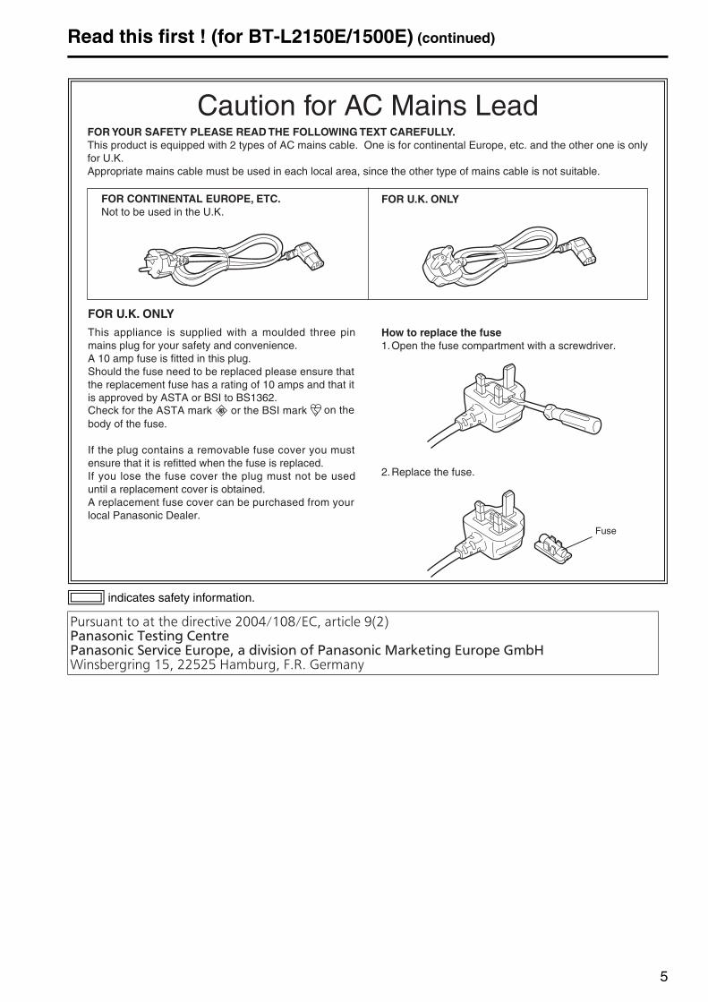
FOR U.K. ONLY
This appliance is supplied with a moulded three pinmains plug for your safety and convenience.A 10 amp fuse is fitted in this plug.Should the fuse need to be replaced please ensure thatthe replacement fuse has a rating of 10 amps and that itis approved by ASTA or BSI to BS1362.Check for the ASTA mark or the BSI mark on thebody of the fuse.
If the plug contains a removable fuse cover you mustensure that it is refitted when the fuse is replaced.If you lose the fuse cover the plug must not be useduntil a replacement cover is obtained.A replacement fuse cover can be purchased from yourlocal Panasonic Dealer.
Caution for AC Mains LeadFOR YOUR SAFETY PLEASE READ THE FOLLOWING TEXT CAREFULLY.This product is equipped with 2 types of AC mains cable. One is for continental Europe, etc. and the other one is onlyfor U.K.Appropriate mains cable must be used in each local area, since the other type of mains cable is not suitable.
FOR CONTINENTAL EUROPE, ETC.Not to be used in the U.K.
FOR U.K. ONLY
How to replace the fuse1.Open the fuse compartment with a screwdriver.
2.Replace the fuse.
Fuse
Read this first ! (for BT-L2150E/1500E) (continued)
6
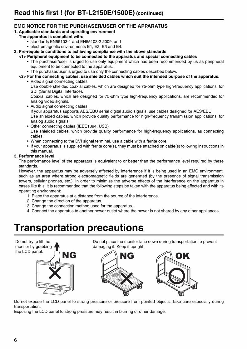
EMC NOTICE FOR THE PURCHASER/USER OF THE APPARATUS1. Applicable standards and operating environment
The apparatus is compliant with:• standards EN55103-1 and EN55103-2 2009, and• electromagnetic environments E1, E2, E3 and E4.
2. Pre-requisite conditions to achieving compliance with the above standards<1> Peripheral equipment to be connected to the apparatus and special connecting cables
• The purchaser/user is urged to use only equipment which has been recommended by us as peripheralequipment to be connected to the apparatus.
• The purchaser/user is urged to use only the connecting cables described below.<2> For the connecting cables, use shielded cables which suit the intended purpose of the apparatus.
• Video signal connecting cablesUse double shielded coaxial cables, which are designed for 75-ohm type high-frequency applications, forSDI (Serial Digital Interface).Coaxial cables, which are designed for 75-ohm type high-frequency applications, are recommended foranalog video signals.
• Audio signal connecting cablesIf your apparatus supports AES/EBU serial digital audio signals, use cables designed for AES/EBU.Use shielded cables, which provide quality performance for high-frequency transmission applications, foranalog audio signals.
• Other connecting cables (IEEE1394, USB)Use shielded cables, which provide quality performance for high-frequency applications, as connectingcables.
• When connecting to the DVI signal terminal, use a cable with a ferrite core.• If your apparatus is supplied with ferrite core(s), they must be attached on cable(s) following instructions in
this manual.3. Performance level
The performance level of the apparatus is equivalent to or better than the performance level required by thesestandards.However, the apparatus may be adversely affected by interference if it is being used in an EMC environment,such as an area where strong electromagnetic fields are generated (by the presence of signal transmissiontowers, cellular phones, etc.). In order to minimize the adverse effects of the interference on the apparatus incases like this, it is recommended that the following steps be taken with the apparatus being affected and with itsoperating environment:
1. Place the apparatus at a distance from the source of the interference.2. Change the direction of the apparatus.3. Change the connection method used for the apparatus.4. Connect the apparatus to another power outlet where the power is not shared by any other appliances.
Transportation precautions
Do not expose the LCD panel to strong pressure or pressure from pointed objects. Take care especially duringtransportation. Exposing the LCD panel to strong pressure may result in blurring or other damage.
Do not place the monitor face down during transportation to prevent damaging it. Keep it upright.
Do not try to lift the monitor by grabbing the LCD panel.
7
About this manual• The BT-L2150P/2150E and the BT-L1500P/1500E is referred to as “the unit” in this manual.• The images and diagrams used in this manual are for reference purposes and may differ from the actual product
and displays.• HDMI, the HDMI logo, and High-Definition Multimedia Interface are trademarks or registered trademarks of
HDMI Licensing LLC in the United States and other countries.• Adobe® Reader® is a trademark of Adobe Systems Incorporated.• Page references are indicated as “( page 00)” in this manual.
Precautions for Use• The LCD monitor is manufactured with high-precision technology and has an effective pixel count of over
99.99 %. However, less than 0.01 % of pixels may be stuck or dead in some cases. This is not a malfunction andhas no effect on the recorded images.
• Wiping the protective panel with a hard cloth, or rubbing it vigorously will scratch the surface.• If a still image is displayed for an extended period of time, it may generate a temporary afterimage (phosphor
burn-in). (However, such images can be removed by displaying normal video for a while.)• The response speed and brightness of liquid crystal vary with ambient temperatures.• Do not install the unit in a place exposed to direct sunlight, as it may damage the cabinet and the LCD screen.• Do not install the unit in locations where enough space cannot be provided around it as heat may build up inside
preventing normal operation. Be sure to provide enough space around the unit.• Exposing the LCD screen to intense light sources will impair its characteristics and lower image quality. • In an environment exposed to drastic temperature fluctuations, condensation may build up on and inside the
LCD screen. This may lower the quality of the screen and may damage it.• Some video images may appear blurred on the screen.• Leaving the unit in a location exposed to high temperature and humidity for an extended period of time may
damage the LCD screen and cause blurring. • Streaks of light may be seen in the area between the edge of the screen and the frame; this is normal and not a
malfunction.• The LCD panel is covered by a protective panel to protect it from damage during transportation. Remove the
protective panel before use.• This unit does not support VIERA Link. If the unit is connected to a VIERA-Link-compatible device via an HDMI
cable, VIERA Link functions on the other device may not operate properly.
8
ContentsRead this first ! (for BT-L2150P/1500P) . . . . . . . . . . 2Read this first ! (for BT-L2150E/1500E) . . . . . . . . . . 4Transportation precautions . . . . . . . . . . . . . . . . . . . 6About this manual . . . . . . . . . . . . . . . . . . . . . . . . . . . 7Precautions for Use . . . . . . . . . . . . . . . . . . . . . . . . . 7Standard accessories . . . . . . . . . . . . . . . . . . . . . . . . 8About PDF manuals . . . . . . . . . . . . . . . . . . . . . . . . . 8
Opening the Operating Instructions ........................ 8Outline . . . . . . . . . . . . . . . . . . . . . . . . . . . . . . . . . . . . 9Dimensions . . . . . . . . . . . . . . . . . . . . . . . . . . . . . . . 10Controls and Their Functions . . . . . . . . . . . . . . . . 11
Video monitor unit ................................................. 11Front panel ............................................................ 12Rear panel............................................................. 13
Power Supply. . . . . . . . . . . . . . . . . . . . . . . . . . . . . . 14Connecting and fixing the power cable ................. 14
Adjusting the Monitor Angle . . . . . . . . . . . . . . . . . 14How to Use the On Screen Menu . . . . . . . . . . . . . . 15
Input signal status ................................................. 15Picture adjusting buttons/VOLUME button status . 15Sharpness display................................................. 15Menu display ......................................................... 16Closed caption (CC) display.................................. 16Menu operations ................................................... 17
Main Menu . . . . . . . . . . . . . . . . . . . . . . . . . . . . . . . . 18
Menu configuration................................................ 18MARKER............................................................... 18MARKER types ..................................................... 19VIDEO CONFIG .................................................... 20SYSTEM CONFIG................................................. 21GPI ........................................................................ 21INPUT SELECT..................................................... 21AUDIO ................................................................... 23DISPLAY SETUP .................................................. 23CONTROL............................................................. 23HOURS METER.................................................... 24
REMOTE Specifications . . . . . . . . . . . . . . . . . . . . . 25GPI terminal .......................................................... 25
Detaching and Attaching the Protective Panel . . . 26Detaching the panel .............................................. 26Attaching the panel................................................ 26
Detaching and Attaching the Tilt Stand . . . . . . . . 27Detaching the tilt stand.......................................... 27Attaching the tilt stand........................................... 27
Maintenance Inspections . . . . . . . . . . . . . . . . . . . . 27Maintenance. . . . . . . . . . . . . . . . . . . . . . . . . . . . . . . 27Specifications . . . . . . . . . . . . . . . . . . . . . . . . . . . . . 28INDEX . . . . . . . . . . . . . . . . . . . . . . . . . . . . . . . . . . . . 30
Standard accessoriesPower cable x 1 (BT-L2150P/1500P)Power cable x 2 (BT-L2150E/1500E)CD-ROM x 1
■ The following supplied accessories are preinstalled on the unit.Protective panel x 1Protective panel screws x 10 (BT-L2150P/BT-L2150E)Protective panel screws x 8 (BT-L1500P/BT-L1500E)
Tilt stand x 1Tilt stand screws x 4
• After removing the product from the package, discard the packaging material properly.
About PDF manualsSupplied CD-ROM is provided with Operating Instructions which are in the form of a PDF(Portable DocumentFormat) file.• You need to have the Adobe® Reader® installed to open and view PDF files.• Download the Adobe® Reader® properly to your computer from the Adobe web site(http://www.adobe.com/).• Refer to the Help menu for details about Adobe® Reader®.
1. Insert the CD-ROM disc into the CD-ROM drive.
2. If the software installation screen opens, click [Cancel] to cancel the installation. To open the CD-ROM,double-click the My Computer icon, rightclick the CD-ROM drive icon, and then click [Open] in thedisplayed shortcut menu.
3. Double-click on the [INDEX.pdf] file on the CD-ROM.• The Adobe® Reader® will start up, and a list of contents for the Operating Instructions will be displayed.
4. Click on a desired document name.• The Operating Instructions selected will open.
Opening the Operating Instructions

9
OutlineDesigned especially for use in professional broadcasting, the BT-L2150P/2150E and the BT-L1500P/1500E comewith a 54.6 cm (21.5-inch) and 39.1 cm (15.4-inch) wide LCD screen, respectively.
■ High performance panelThese monitors achieve outstanding color reproduction, a wide viewing angle, and high-speed response.
■ Multi-format image compatibility • The monitors are equipped with SDI (HD/SD compatible), VIDEO, YPBPR, HDMI (HDCP compatible), PC input
terminals. • They support both NTSC and PAL TV broadcast systems.
■ A host of functions• Marker functions
Aspect marker, safe area marker, center marker and other markers can be displayed in both 16:9 and 4:3aspect ratio.
• Selectable color temperatureWorks with both 6,500 K and 9,300 K color temperatures. The monitors will also allow you to set the white balance at either color temperature.
• Blue-only functionThis function removes the red and green components from the video signal.
• Audio monitoring functionAllows you to monitor audio signals embedded in SDI or HDMI signals or audio signals from the AUDIO INterminal via speakers or headphones.
• Tally lampEquipped with the tally lamp (red, green, amber) on the front. Each color LED can be turned on and off externally using a remote control.
• Closed caption During VIDEO (NTSC) input, this feature displays the closed caption information embedded in the videosignal.(EIA-608 compliant)
• External Remote ControlGPI (D-SUB 9-pin) remote input terminal enables operation from an external.
• Tilt standMonitor stand comes with tilt adjustment as standard. This function allows you to tilt the monitor backward or forward for best viewing angle.
10
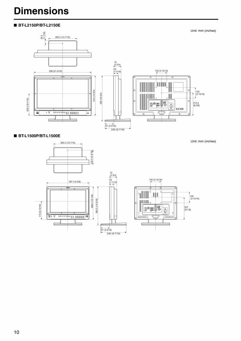
Dimensions■ BT-L2150P/BT-L2150E
■ BT-L1500P/BT-L1500E
205.
5 (8
-1/1
6)
374
(14-
3/4)
538 (21-3/16)
26.5
(1-1
/16)
265.5 (10-7/16)
426
(16-
3/4)
100 (3-15/16)
100(3-15/16)
213.5(8-3/8)
70(2-3/4)
43(1-11/16)
81 (3-3/16)
240 (9-7/16)
Unit: mm (inches)
173
(6-1
3/16
)
397 (15-5/8)
360.
5 (1
4-3/
16)
308.
5 (1
2-1/
8)13
2.5
(5-3
/16)
265.5 (10-7/16)
100 (3-15/16)
100 (3-15/16)
207(8-1/8)
81 (3-3/16)
240 (9-7/16)
70(2-3/4)
43(1-11/16)
Unit: mm (inches)
11
Controls and Their Functions
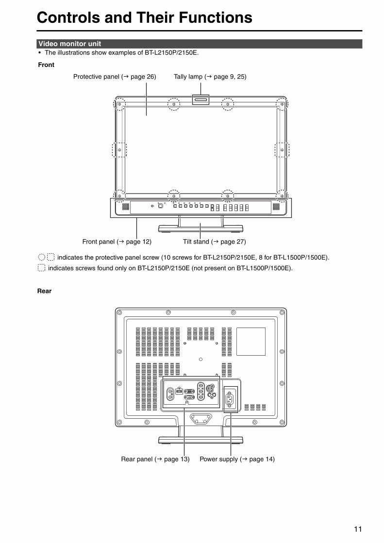
• The illustrations show examples of BT-L2150P/2150E.Video monitor unit
Front
Rear
Rear panel ( page 13) Power supply ( page 14)
Front panel ( page 12)
Tally lamp ( page 9, 25)
indicates the protective panel screw (10 screws for BT-L2150P/2150E, 8 for BT-L1500P/1500E).
indicates screws found only on BT-L2150P/2150E (not present on BT-L1500P/1500E).
Tilt stand ( page 27)
Protective panel ( page 26)
Controls and Their Functions (continued)
12
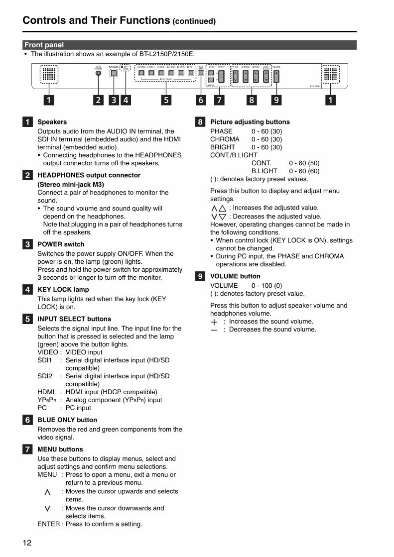
• The illustration shows an example of BT-L2150P/2150E.
SpeakersOutputs audio from the AUDIO IN terminal, the SDI IN terminal (embedded audio) and the HDMI terminal (embedded audio).• Connecting headphones to the HEADPHONES
output connector turns off the speakers.
HEADPHONES output connector (Stereo mini-jack M3)Connect a pair of headphones to monitor the sound.• The sound volume and sound quality will
depend on the headphones. Note that plugging in a pair of headphones turns off the speakers.
POWER switchSwitches the power supply ON/OFF. When the power is on, the lamp (green) lights.Press and hold the power switch for approximately 3 seconds or longer to turn off the monitor.
KEY LOCK lampThis lamp lights red when the key lock (KEY LOCK) is on.
INPUT SELECT buttonsSelects the signal input line. The input line for the button that is pressed is selected and the lamp (green) above the button lights.VIDEO : VIDEO inputSDI1 : Serial digital interface input (HD/SD
compatible)SDI2 : Serial digital interface input (HD/SD
compatible)HDMI : HDMI input (HDCP compatible)YPBPR : Analog component (YPBPR) inputPC : PC input
BLUE ONLY buttonRemoves the red and green components from the video signal.
MENU buttonsUse these buttons to display menus, select and adjust settings and confirm menu selections.MENU : Press to open a menu, exit a menu or
return to a previous menu.: Moves the cursor upwards and selects
items.: Moves the cursor downwards and
selects items.ENTER : Press to confirm a setting.
Picture adjusting buttonsPHASE 0 - 60 (30)CHROMA 0 - 60 (30)BRIGHT 0 - 60 (30)CONT./B.LIGHT
CONT. 0 - 60 (50)B.LIGHT 0 - 60 (60)
( ): denotes factory preset values.
Press this button to display and adjust menu settings.
: Increases the adjusted value.: Decreases the adjusted value.
However, operating changes cannot be made in the following conditions.• When control lock (KEY LOCK is ON), settings
cannot be changed. • During PC input, the PHASE and CHROMA
operations are disabled.
VOLUME buttonVOLUME 0 - 100 (0)( ): denotes factory preset value.
Press this button to adjust speaker volume and headphones volume.
: Increases the sound volume.: Decreases the sound volume.
Front panel
91 12 3 4 5 6 7 8
Controls and Their Functions (continued)
13
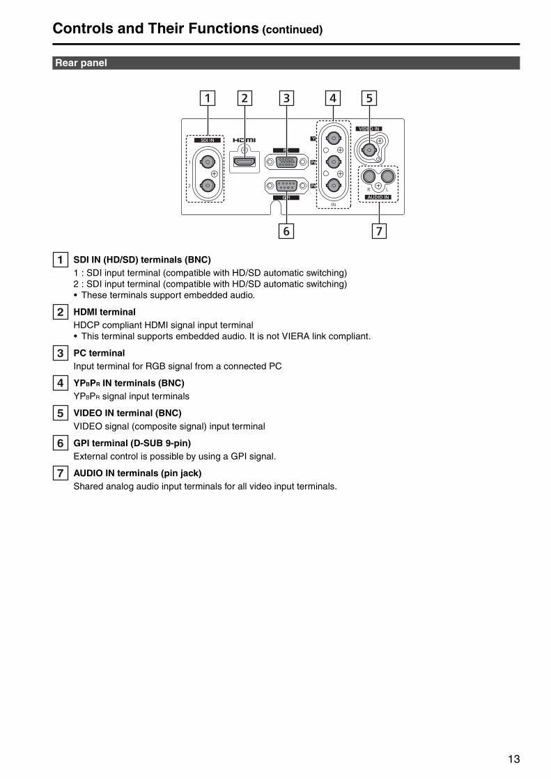
SDI IN (HD/SD) terminals (BNC)1 : SDI input terminal (compatible with HD/SD automatic switching)2 : SDI input terminal (compatible with HD/SD automatic switching)• These terminals support embedded audio.
HDMI terminalHDCP compliant HDMI signal input terminal• This terminal supports embedded audio. It is not VIERA link compliant.
PC terminalInput terminal for RGB signal from a connected PC
YPBPR IN terminals (BNC)YPBPR signal input terminals
VIDEO IN terminal (BNC)VIDEO signal (composite signal) input terminal
GPI terminal (D-SUB 9-pin)External control is possible by using a GPI signal.
AUDIO IN terminals (pin jack)Shared analog audio input terminals for all video input terminals.
Rear panel
1 2 4
6 7
3 5
14
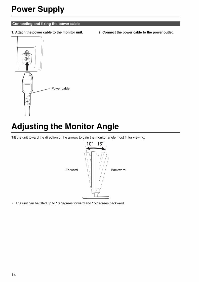
Power Supply
1. Attach the power cable to the monitor unit. 2. Connect the power cable to the power outlet.
Adjusting the Monitor AngleTilt the unit toward the direction of the arrows to gain the monitor angle most fit for viewing.
• The unit can be tilted up to 10 degrees forward and 15 degrees backward.
Connecting and fixing the power cable
Power cable
BackwardForward
15
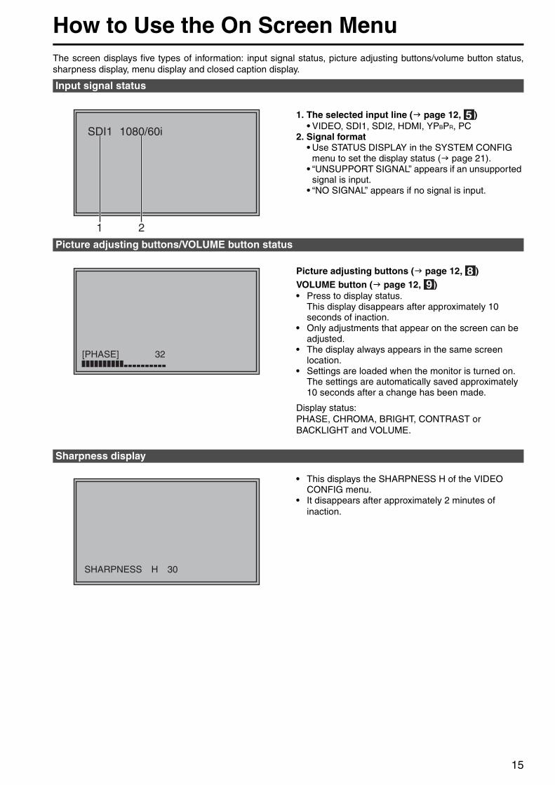
How to Use the On Screen MenuThe screen displays five types of information: input signal status, picture adjusting buttons/volume button status,sharpness display, menu display and closed caption display.
1. The selected input line ( page 12, )• VIDEO, SDI1, SDI2, HDMI, YPBPR, PC
2. Signal format• Use STATUS DISPLAY in the SYSTEM CONFIG
menu to set the display status ( page 21). • “UNSUPPORT SIGNAL” appears if an unsupported
signal is input. • “NO SIGNAL” appears if no signal is input.
Picture adjusting buttons ( page 12, )VOLUME button ( page 12, )• Press to display status.
This display disappears after approximately 10 seconds of inaction.
• Only adjustments that appear on the screen can be adjusted.
• The display always appears in the same screen location.
• Settings are loaded when the monitor is turned on. The settings are automatically saved approximately 10 seconds after a change has been made.
Display status:PHASE, CHROMA, BRIGHT, CONTRAST or BACKLIGHT and VOLUME.
• This displays the SHARPNESS H of the VIDEO CONFIG menu.
• It disappears after approximately 2 minutes of inaction.
Input signal status
Picture adjusting buttons/VOLUME button status
Sharpness display
How to Use the On Screen Menu (continued)
16
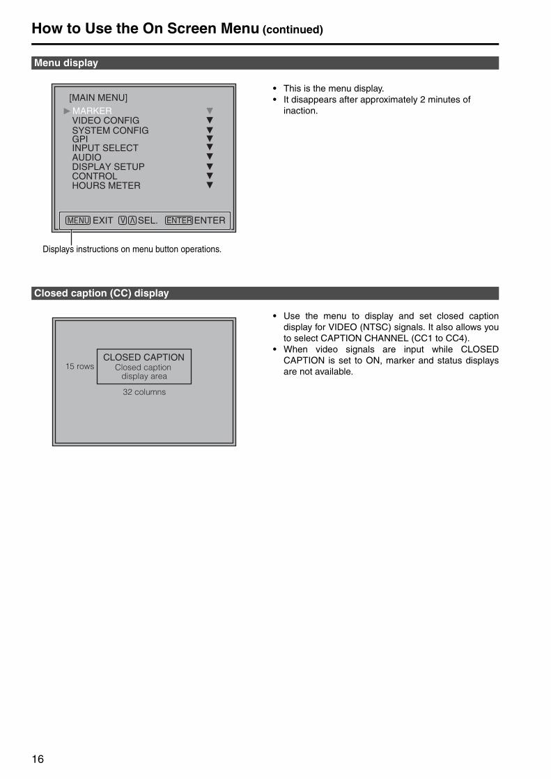
• This is the menu display.• It disappears after approximately 2 minutes of
inaction.
• Use the menu to display and set closed captiondisplay for VIDEO (NTSC) signals. It also allows youto select CAPTION CHANNEL (CC1 to CC4).
• When video signals are input while CLOSEDCAPTION is set to ON, marker and status displaysare not available.
Menu display
[MAIN MENU]
Displays instructions on menu button operations.
Closed caption (CC) display
How to Use the On Screen Menu (continued)
17
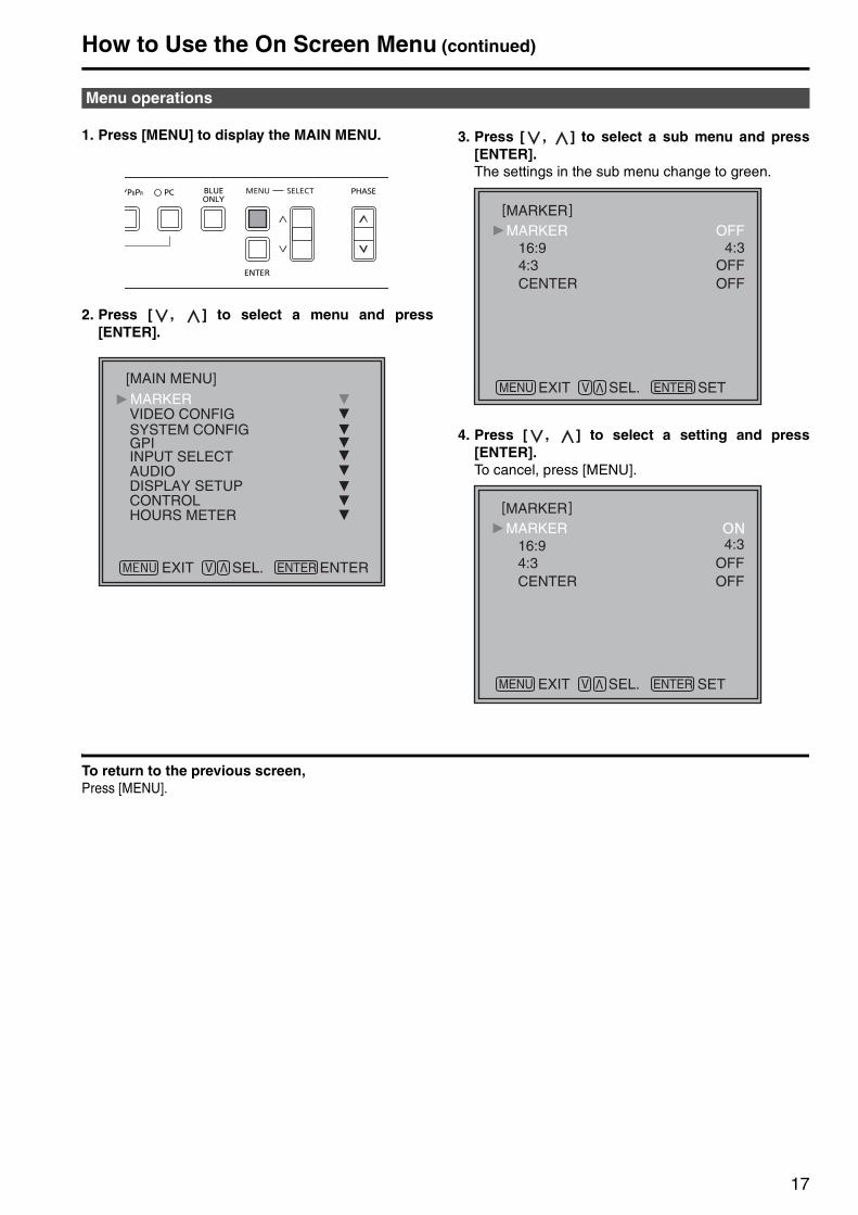
1. Press [MENU] to display the MAIN MENU.
2. Press [ , ] to select a menu and press[ENTER].
3. Press [ , ] to select a sub menu and press[ENTER]. The settings in the sub menu change to green.
4. Press [ , ] to select a setting and press[ENTER]. To cancel, press [MENU].
To return to the previous screen,Press [MENU].
Menu operations
[MAIN MENU]
18
Main Menu
Underlined values indicate factory defaults.
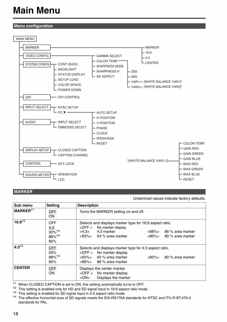
*1 When CLOSED CAPTION is set to ON, this setting automatically turns to OFF.*2 This setting is enabled only for HD and SD signal input in 16:9 aspect ratio mode.*3 This setting is enabled for SD signal input in 4:3 aspect ratio mode.*4 The effective horizontal area of SD signals meets the EIA-RS170A standards for NTSC and ITU-R BT.470-4
standards for PAL.
Menu configuration
MARKER
Sub menu Setting DescriptionMARKER*1
OFFON
Turns the MARKER setting on and off.
16:9*2OFF4:3 93%*4
88%*4
80%
Selects and displays marker type for 16:9 aspect ratio.<OFF > No marker display<4:3> 4:3 marker <88%> 88 % area marker<93%> 93 % area marker <80%> 80 % area marker
4:3*3OFF93%88%*4
80%
Selects and displays marker type for 4:3 aspect ratio.<OFF > No marker display<93%> 93 % area marker <80%> 80 % area marker<88%> 88 % area marker
CENTER OFFON
Displays the center marker.<OFF > No marker display<ON> Displays the marker
MAIN MENU
VIDEO CONFIG
SYSTEM CONFIG
INPUT SELECT
GPI
MARKER
GAMMA SELECT
COLOR TEMP.
SHARPNESS MODE
SHARPNESS H
SD ASPECT
CONT./BACK.
BACKLIGHT
STATUS DISPLAY
SETUP LOAD
COLOR SPACE
POWER DOWN
GPI CONTROL
NTSC SETUP
PC AUTO SETUP
H-POSITION
V-POSITION
PHASE
CLOCK
WXGA/XGA
RESET
AUDIO INPUT SELECT
EMBEDDED SELECT
*[WHITE BALANCE VAR1-2]
MARKER
16:9
4:3
CENTER
COLOR TEMP.
GAIN RED
GAIN GREEN
GAIN BLUE
BIAS RED
BIAS GREEN
BIAS BLUE
RESET
D93
D65
VAR1
VAR2
KEY LOCK
OPERATION
LCD
CONTROL
HOURS METER
DISPLAY SETUP CLOSED CAPTION
CAPTION CHANNEL
[WHITE BALANCE VAR1]*
[WHITE BALANCE VAR2]*

Main Menu (continued)
19
■ 16:9 marker (Displayed for HD input and SD input in 16:9aspect ratio)Aspect marker is only displayed as a vertical bar.The shaded areas are grey in the illustrations toindicate MARKER specifications, but are not grey onthe screen.
Safe area markerSafe area marker is displayed as a dotted line.
■ 4:3 marker (Displayed for SD input in 4:3 aspect ratio)Safe area marker is displayed as a dotted line.
(Displayed for HD input and SD input in 16:9aspect ratio)Safe area marker is displayed as a dotted line.
• You can display the 4:3 marker and the 16:9marker simultaneously.
Simultaneous display example
The shaded areas are grey in the illustrations toindicate MARKER specifications, but are not grey onthe screen.
■ Center marker
MARKER types
4:3 aspect marker
93 % safe area marker 88 % safe area marker
80 % safe area marker
93 % safe area marker 88 % safe area marker
80 % safe area marker
Vertical/Horizontal 93 % Vertical/Horizontal 88 %
Vertical/Horizontal 80 %
Vertical/Horizontal 93 %
Vertical/Horizontal 88 %
Vertical/Horizontal 80 %
93 % safe area marker 88 % safe area marker
80 % safe area marker
For 16:9 :93 % safe area marker
For 4:3 :80 % safe area marker
Center markerThis marker is displayed atthe center of the screen.
Vertical/Horizontal 93 %
Vertical/Horizontal 88 %
Vertical/Horizontal 80 %
16:9 marker
4:3 marker
Main Menu (continued)
20
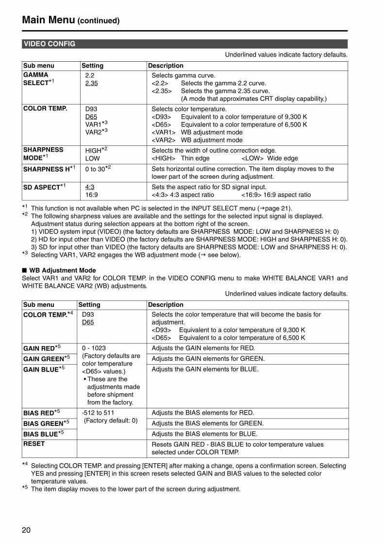
Underlined values indicate factory defaults.
*1 This function is not available when PC is selected in the INPUT SELECT menu ( page 21). *2 The following sharpness values are available and the settings for the selected input signal is displayed.
Adjustment status during selection appears at the bottom right of the screen.1) VIDEO system input (VIDEO) (the factory defaults are SHARPNESS MODE: LOW and SHARPNESS H: 0)2) HD for input other than VIDEO (the factory defaults are SHARPNESS MODE: HIGH and SHARPNESS H: 0).3) SD for input other than VIDEO (the factory defaults are SHARPNESS MODE: LOW and SHARPNESS H: 0).
*3 Selecting VAR1, VAR2 engages the WB adjustment mode ( see below).
■ WB Adjustment ModeSelect VAR1 and VAR2 for COLOR TEMP. in the VIDEO CONFIG menu to make WHITE BALANCE VAR1 andWHITE BALANCE VAR2 (WB) adjustments.
Underlined values indicate factory defaults.
*4 Selecting COLOR TEMP. and pressing [ENTER] after making a change, opens a confirmation screen. Selecting YES and pressing [ENTER] in this screen resets selected GAIN and BIAS values to the selected color temperature values.
*5 The item display moves to the lower part of the screen during adjustment.
VIDEO CONFIG
Sub menu Setting DescriptionGAMMA SELECT*1
2.22.35
Selects gamma curve.<2.2> Selects the gamma 2.2 curve.<2.35> Selects the gamma 2.35 curve.
(A mode that approximates CRT display capability.)
COLOR TEMP. D93D65VAR1*3
VAR2*3
Selects color temperature.<D93> Equivalent to a color temperature of 9,300 K<D65> Equivalent to a color temperature of 6,500 K <VAR1> WB adjustment mode<VAR2> WB adjustment mode
SHARPNESSMODE*1
HIGH*2
LOWSelects the width of outline correction edge.<HIGH> Thin edge <LOW> Wide edge
SHARPNESS H*1 0 to 30*2 Sets horizontal outline correction. The item display moves to the lower part of the screen during adjustment.
SD ASPECT*1 4:316:9
Sets the aspect ratio for SD signal input.<4:3> 4:3 aspect ratio <16:9> 16:9 aspect ratio
Sub menu Setting Description
COLOR TEMP.*4 D93D65
Selects the color temperature that will become the basis for adjustment.<D93> Equivalent to a color temperature of 9,300 K<D65> Equivalent to a color temperature of 6,500 K
GAIN RED*5 0 - 1023(Factory defaults are color temperature <D65> values.)• These are the
adjustments made before shipment from the factory.
Adjusts the GAIN elements for RED.
GAIN GREEN*5 Adjusts the GAIN elements for GREEN.
GAIN BLUE*5 Adjusts the GAIN elements for BLUE.
BIAS RED*5 -512 to 511 (Factory default: 0)
Adjusts the BIAS elements for RED.
BIAS GREEN*5 Adjusts the BIAS elements for GREEN.
BIAS BLUE*5 Adjusts the BIAS elements for BLUE.
RESET Resets GAIN RED - BIAS BLUE to color temperature values selected under COLOR TEMP.

Main Menu (continued)
21
Underlined values indicate factory defaults.
*1 Factory default setting for the BT-L2150P/1500P.*2 Factory default setting for the BT-L2150E/1500E.*3 ITU-709 is an ITU-R BT.709 standard.
Enables and disables all GPI functions enabled by GPI CONTROL.Underlined values indicate factory defaults.
Underlined values indicate factory defaults.
SYSTEM CONFIG
Sub menu Setting Description
CONT./BACK. BACKLIGHTCONTRAST
Selects function to be assigned to the CONT./B.LIGHT front panel buttons.<BACKLIGHT> Adjusts the B.LIGHT (backlight). <CONTRAST> Adjusts the CONT. (contrast).
BACKLIGHT 0 to 60 Adjusts LCD backlight brightness. Adjust as required by ambient conditions.
STATUS DISPLAY CONTINUE3SEC OFFOFF
Sets display state for input signal status (on-screen menu).<CONTINUE> Displayed at all times. <3SEC OFF> Displayed for approximately 3 seconds after a status
change.<OFF > Not displayed.
SETUP LOAD FACTORY Loads saved factory defaults (FACTORY).
COLOR SPACE SMPTE-C*1
EBU*2
ITU-709*3
Sets the studio standard color shade.
POWER DOWN OFFON
Selects whether monitor power shuts off (POWER DOWN) when no operation has taken place for a preset period of time and no input signal is present.<OFF> Disables POWER DOWN.<ON> Enables POWER DOWN.
GPI
Sub menu Setting Description
GPI CONTROL DISABLEENABLE
Enables and disables GPI functions<DISABLE> Disabled<ENABLE> Enabled
INPUT SELECT
Sub menu Setting Description
NTSC SETUP 7500
Selects NTSC setup level.<75> Select this function when using 7.5 % setup signals.
(Adjusts the interior of the monitor to the 7.5 % setup level to suit the black level)
<00> Select this when there is no setup signal.PC Performs analog PC settings.(PC page 22)
Main Menu (continued)
22
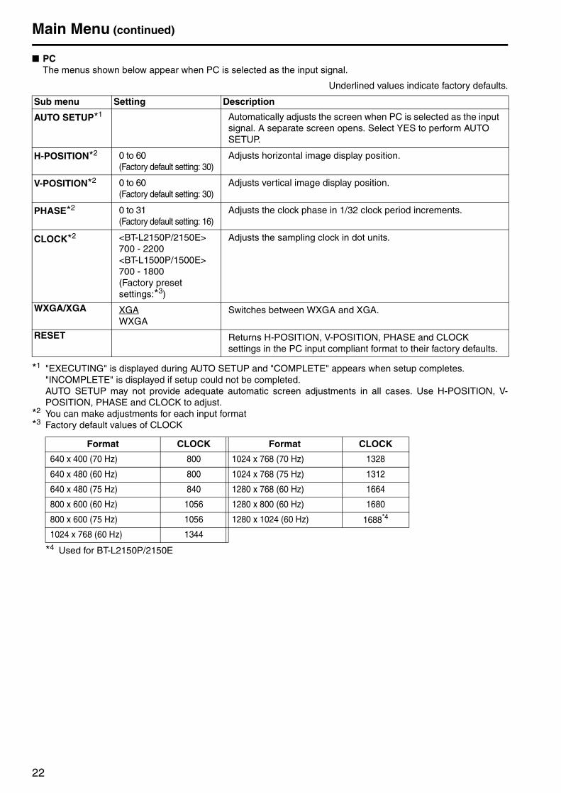
■ PCThe menus shown below appear when PC is selected as the input signal.
Underlined values indicate factory defaults.
*1 "EXECUTING" is displayed during AUTO SETUP and "COMPLETE" appears when setup completes."INCOMPLETE" is displayed if setup could not be completed.AUTO SETUP may not provide adequate automatic screen adjustments in all cases. Use H-POSITION, V-POSITION, PHASE and CLOCK to adjust.
*2 You can make adjustments for each input format*3 Factory default values of CLOCK
*4 Used for BT-L2150P/2150E
Sub menu Setting Description
AUTO SETUP*1 Automatically adjusts the screen when PC is selected as the input signal. A separate screen opens. Select YES to perform AUTO SETUP.
H-POSITION*2 0 to 60(Factory default setting: 30)
Adjusts horizontal image display position.
V-POSITION*2 0 to 60(Factory default setting: 30)
Adjusts vertical image display position.
PHASE*2 0 to 31(Factory default setting: 16)
Adjusts the clock phase in 1/32 clock period increments.
CLOCK*2 <BT-L2150P/2150E>700 - 2200<BT-L1500P/1500E>700 - 1800(Factory preset settings:*3)
Adjusts the sampling clock in dot units.
WXGA/XGA XGAWXGA
Switches between WXGA and XGA.
RESET Returns H-POSITION, V-POSITION, PHASE and CLOCK settings in the PC input compliant format to their factory defaults.
Format CLOCK Format CLOCK
640 x 400 (70 Hz) 800 1024 x 768 (70 Hz) 1328
640 x 480 (60 Hz) 800 1024 x 768 (75 Hz) 1312
640 x 480 (75 Hz) 840 1280 x 768 (60 Hz) 1664
800 x 600 (60 Hz) 1056 1280 x 800 (60 Hz) 1680
800 x 600 (75 Hz) 1056 1280 x 1024 (60 Hz) 1688*4
1024 x 768 (60 Hz) 1344
Main Menu (continued)
23
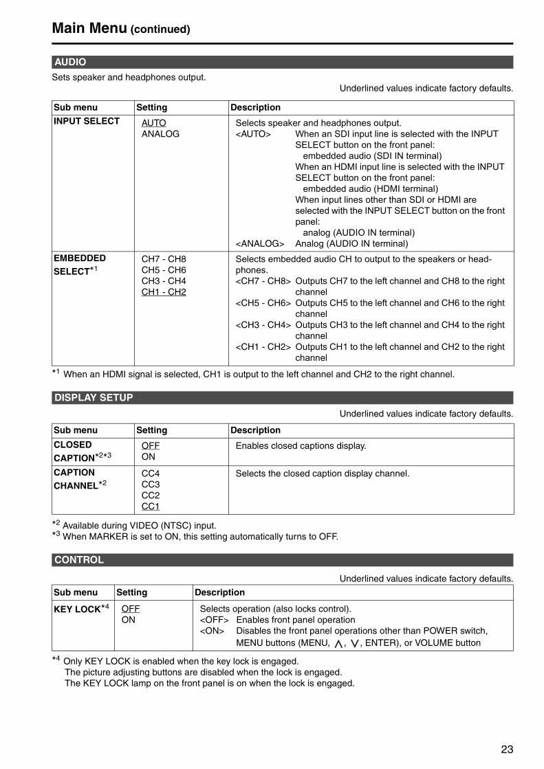
Sets speaker and headphones output.Underlined values indicate factory defaults.
*1 When an HDMI signal is selected, CH1 is output to the left channel and CH2 to the right channel.
Underlined values indicate factory defaults.
*2 Available during VIDEO (NTSC) input.*3 When MARKER is set to ON, this setting automatically turns to OFF.
Underlined values indicate factory defaults.
*4 Only KEY LOCK is enabled when the key lock is engaged.The picture adjusting buttons are disabled when the lock is engaged. The KEY LOCK lamp on the front panel is on when the lock is engaged.
AUDIO
Sub menu Setting Description
INPUT SELECT AUTOANALOG
Selects speaker and headphones output.<AUTO> When an SDI input line is selected with the INPUT
SELECT button on the front panel:embedded audio (SDI IN terminal)
When an HDMI input line is selected with the INPUT SELECT button on the front panel:
embedded audio (HDMI terminal)When input lines other than SDI or HDMI are selected with the INPUT SELECT button on the front panel:
analog (AUDIO IN terminal)<ANALOG> Analog (AUDIO IN terminal)
EMBEDDED SELECT*1
CH7 - CH8CH5 - CH6CH3 - CH4CH1 - CH2
Selects embedded audio CH to output to the speakers or head-phones.<CH7 - CH8> Outputs CH7 to the left channel and CH8 to the right
channel<CH5 - CH6> Outputs CH5 to the left channel and CH6 to the right
channel<CH3 - CH4> Outputs CH3 to the left channel and CH4 to the right
channel<CH1 - CH2> Outputs CH1 to the left channel and CH2 to the right
channel
DISPLAY SETUP
Sub menu Setting Description
CLOSED CAPTION*2*3
OFFON
Enables closed captions display.
CAPTIONCHANNEL*2
CC4CC3CC2CC1
Selects the closed caption display channel.
CONTROL
Sub menu Setting Description
KEY LOCK*4 OFFON
Selects operation (also locks control).<OFF> Enables front panel operation <ON> Disables the front panel operations other than POWER switch,
MENU buttons (MENU, , , ENTER), or VOLUME button
Main Menu (continued)
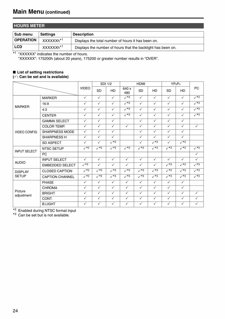
24
*1 "XXXXXX" indicates the number of hours."XXXXXX": 175200h (about 20 years), 175200 or greater number results in “OVER”.
■ List of setting restrictions( : Can be set and is available)
*2 Enabled during NTSC format input*3 Can be set but is not available.
HOURS METER
Sub menu Settings Description
OPERATION XXXXXXh*1 Displays the total number of hours it has been on.
LCD XXXXXXh*1 Displays the number of hours that the backlight has been on.
VIDEOSDI 1/2 HDMI YPBPR
PCSD HD
640 x 480
SD HD SD HD
MARKER
MARKER *3 *3
16:9 *3 *3
4:3 *3 *3
CENTER *3 *3
VIDEO CONFIG
GAMMA SELECT
COLOR TEMP.
SHARPNESS MODE
SHARPNESS H
SD ASPECT *3 *3 *3
INPUT SELECTNTSC SETUP *2 *3 *3 *3 *3 *3 *3 *3 *3
PC
AUDIOINPUT SELECT
EMBEDDED SELECT *3 *3 *3 *3
DISPLAYSETUP
CLOSED CAPTION *2 *3 *3 *3 *3 *3 *3 *3 *3
CAPTION CHANNEL *2 *3 *3 *3 *3 *3 *3 *3 *3
Picture adjustment
PHASE
CHROMA
BRIGHT
CONT.
B.LIGHT

25
REMOTE SpecificationsThis monitor permits remote operation from an external.
GPI screen items correspond to the following terminals.The functions assigned to each terminal operate when GND (pin 5) is short-circuited (ON) or open (OFF).
■ Operating conditionsLevel operation: Operates when GND is short-
circuited.Edge operation: Operates when GND changes from
open to short-circuited.• Edge operation should be maintained for
approximately 0.2 s or more after a change.
*1 When R-TALLY and G-TALLY simultaneously go on, the tally lamp's color changes to amber.
GPI terminal
Pin Signal1 GPI12 GPI2
GPI terminals (9P) 3 GPI34 GPI45 GND6 GPI57 GPI68 GPI79 GPI8
Terminal Assigned item Function Operating conditionsGPI1 INPUT SEL. VIDEO Switches the input line to VIDEO. Edge operation
GPI2 INPUT SEL. SDI1 Switches the input line to SDI1. Edge operation
GPI3 INPUT SEL. SDI2 Switches the input line to SDI2. Edge operation
GPI4 INPUT SEL. HDMI Switches the input line to HDMI. Edge operation
GPI5 INPUT SEL. YPBPR Switches the input line to YPBPR. Edge operation
GPI6 INPUT SEL. PC Switches the input line to PC. Edge operation
GPI7 R-TALLY*1 Lights the red tally lamp. Level operation(Short-circuited: ON, Open: OFF)
GPI8 G-TALLY*1 Lights the green tally lamp. Level operation(Short-circuited: ON, Open: OFF)
26
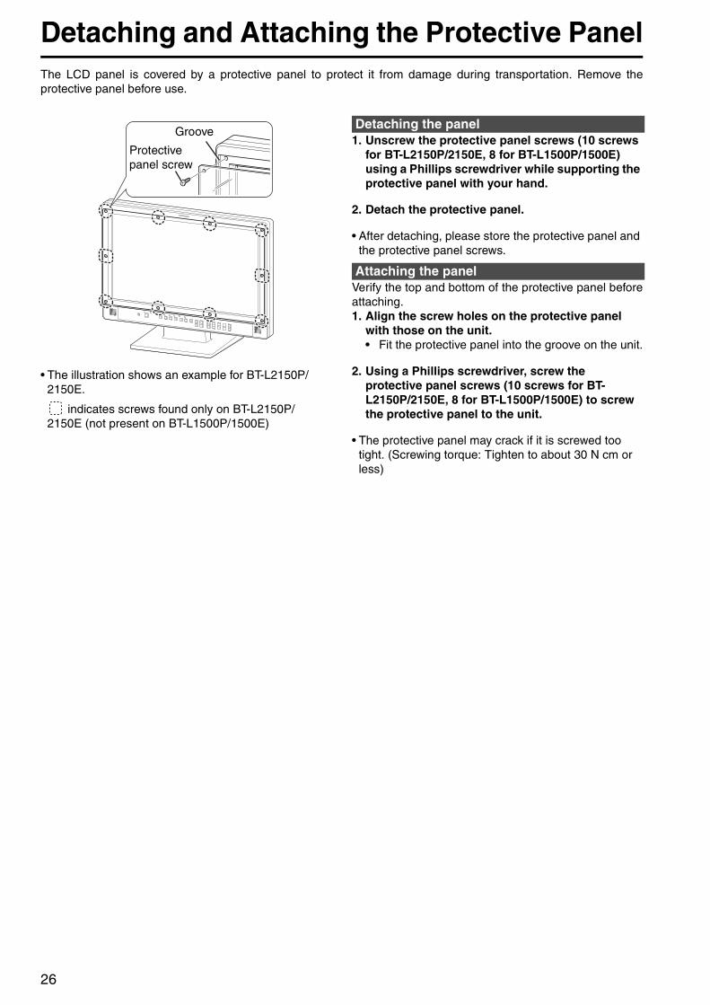
Detaching and Attaching the Protective PanelThe LCD panel is covered by a protective panel to protect it from damage during transportation. Remove theprotective panel before use.
• The illustration shows an example for BT-L2150P/2150E.
indicates screws found only on BT-L2150P/2150E (not present on BT-L1500P/1500E)
1. Unscrew the protective panel screws (10 screws for BT-L2150P/2150E, 8 for BT-L1500P/1500E) using a Phillips screwdriver while supporting the protective panel with your hand.
2. Detach the protective panel.
• After detaching, please store the protective panel and the protective panel screws.
Verify the top and bottom of the protective panel beforeattaching.1. Align the screw holes on the protective panel
with those on the unit.• Fit the protective panel into the groove on the unit.
2. Using a Phillips screwdriver, screw the protective panel screws (10 screws for BT-L2150P/2150E, 8 for BT-L1500P/1500E) to screw the protective panel to the unit.
• The protective panel may crack if it is screwed too tight. (Screwing torque: Tighten to about 30 N cm or less)
Protectivepanel screw
GrooveDetaching the panel
Attaching the panel
27
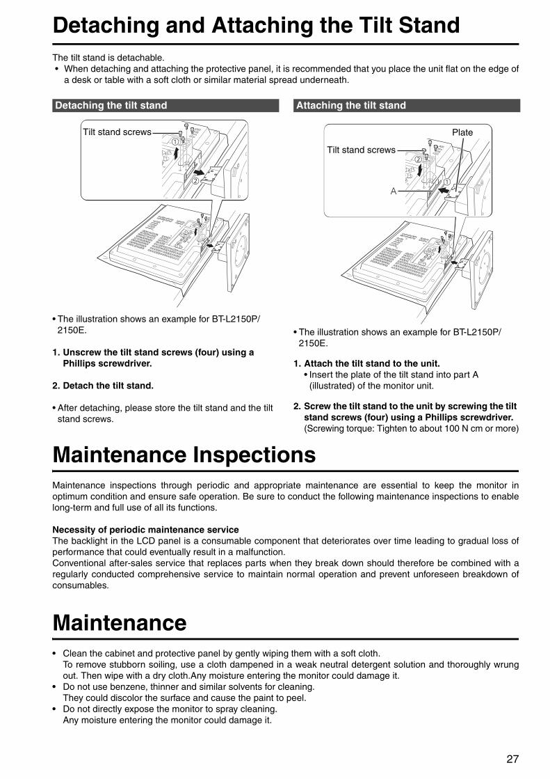
Detaching and Attaching the Tilt StandThe tilt stand is detachable.• When detaching and attaching the protective panel, it is recommended that you place the unit flat on the edge of
a desk or table with a soft cloth or similar material spread underneath.
• The illustration shows an example for BT-L2150P/2150E.
1. Unscrew the tilt stand screws (four) using a Phillips screwdriver.
2. Detach the tilt stand.
• After detaching, please store the tilt stand and the tilt stand screws.
• The illustration shows an example for BT-L2150P/2150E.
1. Attach the tilt stand to the unit.• Insert the plate of the tilt stand into part A
(illustrated) of the monitor unit.
2. Screw the tilt stand to the unit by screwing the tilt stand screws (four) using a Phillips screwdriver.(Screwing torque: Tighten to about 100 N cm or more)
Maintenance InspectionsMaintenance inspections through periodic and appropriate maintenance are essential to keep the monitor inoptimum condition and ensure safe operation. Be sure to conduct the following maintenance inspections to enablelong-term and full use of all its functions.
Necessity of periodic maintenance serviceThe backlight in the LCD panel is a consumable component that deteriorates over time leading to gradual loss ofperformance that could eventually result in a malfunction.Conventional after-sales service that replaces parts when they break down should therefore be combined with aregularly conducted comprehensive service to maintain normal operation and prevent unforeseen breakdown ofconsumables.
Maintenance• Clean the cabinet and protective panel by gently wiping them with a soft cloth.
To remove stubborn soiling, use a cloth dampened in a weak neutral detergent solution and thoroughly wrungout. Then wipe with a dry cloth.Any moisture entering the monitor could damage it.
• Do not use benzene, thinner and similar solvents for cleaning.They could discolor the surface and cause the paint to peel.
• Do not directly expose the monitor to spray cleaning.Any moisture entering the monitor could damage it.
Detaching the tilt stand
Tilt stand screws
Attaching the tilt stand
A
Plate
Tilt stand screws
28
Specifications■ GeneralPower input
Dimensions (W x H x D): <BT-L2150P/2150E>
538 mm x 426 mm x 240 mm(21-3/16 inches x 16-3/4 inches x 9-7/16 inches)(including tilt stand)538 mm x 374 mm x 70 mm(21-3/16 inches x 14-3/4 inches x 2-3/4 inches)(monitor only, not including tilt stand)
<BT-L1500P/1500E>397 mm x 360.5 mm x 240 mm(including tilt stand)(15-5/8 inches x 14-3/16 inches x 9-7/16 inches)397 mm x 308.5 mm x 70 mm(15-5/8 inches x 12-1/8 inches x 2-3/4 inches)(monitor only, not including tilt stand)
Mass:<BT-L2150P/2150E>
Approx. 7.5 kg (16.53 lb) (including tilt stand)Approx. 6.0 kg (13.23 lb) (monitor only, not including tilt stand)
<BT-L1500P/1500E>Approx. 5.4 kg (11.9 lb) (including tilt stand)Approx. 3.9 kg (8.6 lb) (monitor only, not including tilt stand)
Operating temperature: 5 °C to 35 °C (41 °F to 95 °F)
Operating humidity:20 % to 80 % (no condensation)
Storage temperature:- 20 °C to 60 °C (-4 °F to 140 °F)
■ Display panel<BT-L2150P/2150E>Dimensions: 54.6 cm (21.5-inch) (effective screen
area)Aspect ratio: 16:9Number of pixels:
1920 x 1080 (FULL HD)Display colors: Approx. 16,700,000 colorsView angle (contrast > 10:1):
160° up/down, 170° right/left
<BT-L1500P/1500E>Dimensions: 39.1 cm (15.4-inch) (effective screen
area)Aspect ratio: 16:10Number of pixels:
1280 x 800 (WXGA)Display colors: Approx. 16,200,000 colorsView angle (contrast > 10:1):
140° up/down, 160° right/left
■ Input/output ConnectorsVideo signal input:
VIDEO IN terminal: 1 input, BNC x 1
YPBPR IN terminal (Analog component):1 input, BNC x 3
SDI IN (HD/SD) terminals:SMPTE274M/296M/259M-C/ITU-R BT.656-4 compliant 2 inputs, BNC x 2
HDMI terminals: 1 input, HDMI terminal x 1 (TYPE A) HDCP compatible, not VIERA LINK compatible
PC terminal: 1 input, D-SUB, 15-pin x 1<BT-L2150P/2150E>Vertical frequency:
60.0 Hz - 75.0 HzHorizontal frequency:
31.5 kHz - 64.0 kHzDot clock: 25 MHz - 108 MHz<BT-L1500P/1500E>Vertical Frequency:
60.0 Hz - 75.0 HzHorizontal frequency:
31.5 kHz - 60.0 kHzDot clock: 25 MHz - 83.5 MHzHD/VD signal level:
TTL levelAudio input:
SDI IN (HD/SD) terminals:EMBEDDED AUDIOHD - SDI: SMPTE299M compliant
Sampling rate: 48 kHz, synchronous/asynchronous, 8 ch
SD - SDI: SMPTE272M compliantSampling rate: 48 kHz, synchronous, 4 ch
HDMI terminal:EMBEDDED AUDIO
AUDIO IN terminal (Analog audio input): Pin jack x 2 (stereo)Input level 0.5 Vrms
Speaker output: 0.5 W + 0.5 WHeadphone output: Stereo minijack
M3 x 1, 32 Ωadjustable level
GPI terminal: D-SUB, 9-pin x 1
<BT-L2150P/2150E>
AC:Power supply100 V - 240 V, 50/60 Hz
Current consumption0.60 A - 0.30 A
<BT-L1500P/1500E>
AC:Power supply100 V - 240 V, 50/60 Hz
Current consumption0.50 A - 0.25 A
indicates safety information.
Inrush current, measured according to European stan-dard EN55103-1: 11.0 A
Specifications (continued)
29
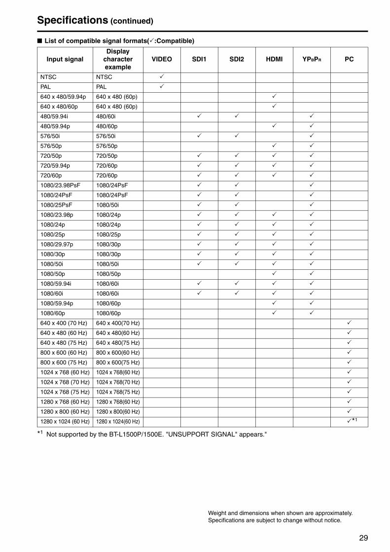
■ List of compatible signal formats( :Compatible)
*1 Not supported by the BT-L1500P/1500E. "UNSUPPORT SIGNAL" appears."
Input signalDisplay
character example
VIDEO SDI1 SDI2 HDMI YPBPR PC
NTSC NTSC
PAL PAL
640 x 480/59.94p 640 x 480 (60p)
640 x 480/60p 640 x 480 (60p)
480/59.94i 480/60i
480/59.94p 480/60p
576/50i 576/50i
576/50p 576/50p
720/50p 720/50p
720/59.94p 720/60p
720/60p 720/60p
1080/23.98PsF 1080/24PsF
1080/24PsF 1080/24PsF
1080/25PsF 1080/50i
1080/23.98p 1080/24p
1080/24p 1080/24p
1080/25p 1080/25p
1080/29.97p 1080/30p
1080/30p 1080/30p
1080/50i 1080/50i
1080/50p 1080/50p
1080/59.94i 1080/60i
1080/60i 1080/60i
1080/59.94p 1080/60p
1080/60p 1080/60p
640 x 400 (70 Hz) 640 x 400(70 Hz)
640 x 480 (60 Hz) 640 x 480(60 Hz)
640 x 480 (75 Hz) 640 x 480(75 Hz)
800 x 600 (60 Hz) 800 x 600(60 Hz)
800 x 600 (75 Hz) 800 x 600(75 Hz)
1024 x 768 (60 Hz) 1024 x 768(60 Hz)
1024 x 768 (70 Hz) 1024 x 768(70 Hz)
1024 x 768 (75 Hz) 1024 x 768(75 Hz)
1280 x 768 (60 Hz) 1280 x 768(60 Hz)
1280 x 800 (60 Hz) 1280 x 800(60 Hz)
1280 x 1024 (60 Hz) 1280 x 1024(60 Hz) *1
Weight and dimensions when shown are approximately.Specifications are subject to change without notice.

30
INDEXNumerics16:9......................................................................................184:3........................................................................................18AAccessories ...........................................................................8Adjusting angle ....................................................................14Aspect marker......................................................................19AUDIO .................................................................................23AUDIO IN terminals .............................................................13AUTO SETUP......................................................................22BBACKLIGHT ........................................................................21BIAS BLUE ..........................................................................20BIAS GREEN.......................................................................20BIAS RED ............................................................................20BLUE ONLY button..............................................................12CCAPTION CHANNEL...........................................................23CENTER ..............................................................................18Center marker ......................................................................19CLOCK ................................................................................22CLOSED CAPTION ...................................................... 16, 23COLOR SPACE...................................................................21COLOR TEMP. ....................................................................20CONT./BACK.......................................................................21CONTROL ...........................................................................23
DDimensions ..........................................................................10DISPLAY SETUP.................................................................23
EEMBEDDED SELECT..........................................................23GGAIN BLUE..........................................................................20GAIN GREEN ......................................................................20GAIN RED ...........................................................................20GAMMA SELECT ................................................................20GPI.......................................................................................21GPI CONTROL ....................................................................21GPI terminal .................................................................. 13, 25HHDMI terminal ......................................................................13HEADPHONES output connector ........................................12HOURS METER ..................................................................24H-POSITION........................................................................22
IINPUT SELECT ............................................................ 21, 23INPUT SELECT buttons ......................................................12Input signal ..........................................................................15KKEY LOCK...........................................................................23KEY LOCK lamp ..................................................................12LLCD......................................................................................24
MMaintenance ........................................................................27Maintenance inspections .....................................................27MARKER ...................................................................... 18, 19
Types ............................................................................19Menu....................................................................................15
Configuration.................................................................18Display ..........................................................................16Operations ....................................................................17
MENU buttons .....................................................................12
NNTSC SETUP...................................................................... 21
OOPERATION ....................................................................... 24PPC terminal.......................................................................... 13PHASE ................................................................................ 22Picture adjusting buttons .............................................. 12, 15POWER DOWN................................................................... 21Power Supply ...................................................................... 14POWER switch .................................................................... 12Protective panel................................................................... 26RREMOTE ............................................................................. 25RESET.......................................................................... 20, 22SSafe area marker................................................................. 19SD ASPECT ........................................................................ 20SDI IN (HD/SD) terminals.................................................... 13SETUP LOAD...................................................................... 21Sharpness ........................................................................... 15SHARPNESS H................................................................... 20SHARPNESS MODE........................................................... 20Speakers ............................................................................. 12Specifications ...................................................................... 28STATUS DISPLAY .............................................................. 21SYSTEM CONFIG............................................................... 21TTilt stand .............................................................................. 27
VVIDEO CONFIG .................................................................. 20VIDEO IN terminal ............................................................... 13VOLUME button ........................................................... 12, 15V-POSITION........................................................................ 22WWB adjustment mode .......................................................... 20WXGA/XGA......................................................................... 22YYPBPR IN terminals.............................................................. 13

31
MEMO

© 2011
Web Site: http://panasonic.net
Information on Disposal for Users of Waste Electrical & Electronic Equipment (private households)
This symbol on the products and/or accompanying documents means that used electrical and electronic products should not be mixed with general household waste.For proper treatment, recovery and recycling, please take these products to designated collection points, where they will be accepted on a free of charge basis. Alternatively, in some countries you may be able to return your products to your local retailer upon the purchase of an equivalent new product.Disposing of this product correctly will help to save valuable resources and prevent any potential negative effects on human health and the environment which could otherwise arise from inappropriate waste handling. Please contact your local authority for further details of your nearest designated collection point.Penalties may be applicable for incorrect disposal of this waste, in accordance with national legislation.
For business users in the European UnionIf you wish to discard electrical and electronic equipment, please contact your dealer or supplier for further information.
Information on Disposal in other Countries outside the European UnionThis symbol is only valid in the European Union.If you wish to discard this product, please contact your local authorities or dealer and ask for the correct method of disposal.