operating instructions and parts manual jbg series bench grinders
TRANSCRIPT

Operating Instructions and Parts Manual JBG Series Bench Grinders Models: JBG-6A, JBG-8A, JBG-10A
Model JBG-8A shown
WALTER MEIER (Manufacturing), Inc. 427 New Sanford Road LaVergne, Tennessee 37086 Part No. M-577101 Ph.: 800-274-6848 Revision J 01/2011 www.waltermeier.com Copyright © 2011 Walter Meier (Manufacturing), Inc.

2
Warranty and Service Walter Meier (Manufacturing) Inc., warrants every product it sells. If one of our tools needs service or repair, one of our Authorized Service Centers located throughout the United States can give you quick service. In most cases, any of these Walter Meier Authorized Service Centers can authorize warranty repair, assist you in obtaining parts, or perform routine maintenance and major repair on your JET® tools. For the name of an Authorized Service Center in your area call 1-800-274-6848. MORE INFORMATION Walter Meier is consistently adding new products to the line. For complete, up-to-date product information, check with your local Walter Meier distributor, or visit waltermeier.com. WARRANTY JET products carry a limited warranty which varies in duration based upon the product (MW = Metalworking, WW = Woodworking).
WHAT IS COVERED? This warranty covers any defects in workmanship or materials subject to the exceptions stated below. Cutting tools, abrasives and other consumables are excluded from warranty coverage. WHO IS COVERED? This warranty covers only the initial purchaser of the product. WHAT IS THE PERIOD OF COVERAGE? The general JET warranty lasts for the time period specified in the product literature of each product. WHAT IS NOT COVERED? Five Year Warranties do not cover woodworking (WW) products used for commercial, industrial or educational purposes. Woodworking products with Five Year Warranties that are used for commercial, industrial or education purposes revert to a One Year Warranty. This warranty does not cover defects due directly or indirectly to misuse, abuse, negligence or accidents, normal wear-and-tear, improper repair or alterations, or lack of maintenance. HOW TO GET SERVICE The product or part must be returned for examination, postage prepaid, to a location designated by us. For the name of the location nearest you, please call 1-800-274-6848. You must provide proof of initial purchase date and an explanation of the complaint must accompany the merchandise. If our inspection discloses a defect, we will repair or replace the product, or refund the purchase price, at our option. We will return the repaired product or replacement at our expense unless it is determined by us that there is no defect, or that the defect resulted from causes not within the scope of our warranty in which case we will, at your direction, dispose of or return the product. In the event you choose to have the product returned, you will be responsible for the shipping and handling costs of the return. HOW STATE LAW APPLIES This warranty gives you specific legal rights; you may also have other rights which vary from state to state. LIMITATIONS ON THIS WARRANTY WALTER MEIER (MANUFACTURING) INC., LIMITS ALL IMPLIED WARRANTIES TO THE PERIOD OF THE LIMITED WARRANTY FOR EACH PRODUCT. EXCEPT AS STATED HEREIN, ANY IMPLIED WARRANTIES OR MERCHANTABILITY AND FITNESS ARE EXCLUDED. SOME STATES DO NOT ALLOW LIMITATIONS ON HOW LONG THE IMPLIED WARRANTY LASTS, SO THE ABOVE LIMITATION MAY NOT APPLY TO YOU. WALTER MEIER SHALL IN NO EVENT BE LIABLE FOR DEATH, INJURIES TO PERSONS OR PROPERTY, OR FOR INCIDENTAL, CONTINGENT, SPECIAL, OR CONSEQUENTIAL DAMAGES ARISING FROM THE USE OF OUR PRODUCTS. SOME STATES DO NOT ALLOW THE EXCLUSION OR LIMITATION OF INCIDENTAL OR CONSEQUENTIAL DAMAGES, SO THE ABOVE LIMITATION OR EXCLUSION MAY NOT APPLY TO YOU. Walter Meier sells through distributors only. The specifications in Walter Meier catalogs are given as general information and are not binding. Members of Walter Meier reserve the right to effect at any time, without prior notice, those alterations to parts, fittings, and accessory equipment which they may deem necessary for any reason whatsoever. JET® branded products are not sold in Canada by Walter Meier.

3
Table of Contents Warranty and Service..........................................................................................................................2 Table of Contents ...............................................................................................................................3 Warnings............................................................................................................................................4 Introduction ........................................................................................................................................6 Specifications .....................................................................................................................................6 Unpacking ..........................................................................................................................................7
Contents of the Shipping Container ..................................................................................................7 Assembly ...........................................................................................................................................8
Assembling the Spark Guard and Eye Shield Mounting Brackets ........................................................8 Installing the Spark Guard and Eye Shield Mounting Brackets ............................................................9 Tool Rests ......................................................................................................................................9 Eye Shields.....................................................................................................................................9 Mounting the Grinder .......................................................................................................................9
Electrical .......................................................................................................................................... 10 Electrical Requirements ................................................................................................................. 10 Electrical Connections ................................................................................................................... 10 Extension Cords ............................................................................................................................ 10
Operation ......................................................................................................................................... 11 Switch .......................................................................................................................................... 11 Precautions................................................................................................................................... 11
Adjustments ..................................................................................................................................... 11 Eye Shield Tilt Adjustment ............................................................................................................. 11 Spark Guard ................................................................................................................................. 11 Tool Rest ...................................................................................................................................... 11
Maintenance .................................................................................................................................... 12 Ring Test ...................................................................................................................................... 12 Care of Grinding Wheel ................................................................................................................. 12 Changing Wheels .......................................................................................................................... 12 Grinding Wheels............................................................................................................................ 13 Wire Wheel Brushes ...................................................................................................................... 13 Cleaning ....................................................................................................................................... 13
Lubrication ....................................................................................................................................... 13 Troubleshooting ................................................................................................................................ 14 Parts and Assembly for JBG Series Grinders...................................................................................... 15
Parts List ...................................................................................................................................... 15 Assembly Drawing......................................................................................................................... 18
Wiring Diagram................................................................................................................................. 19 Ordering Replacement Parts ............................................................................................................. 20
The specifications in this manual are given as general information and are not binding. Walter Meier (Manufacturing) Inc., reserves the right to effect, at any time and without prior notice, changes or alterations to parts, fittings, and accessory equipment deemed necessary for any reason whatsoever.

4
Warnings
1. For your own safety read instruction manual before operating grinder.
2. Read and understand the entire owner’s manual before attempting assembly or operation.
3. Read and understand the warnings posted on the machine and in this manual. Failure to comply with all of these warnings may cause serious injury.
4. Replace the warning labels if they become obscured or removed.
5. This bench grinder is designed and intended for use by properly trained and experienced personnel only. If you are not familiar with the proper and safe operation of a bench grinder, do not use until proper training and knowledge have been obtained.
6. Do not use this bench grinder for other than its intended use. If used for other purposes, Walter Meier (Manufacturing), Inc. disclaims any real or implied warranty and holds itself harmless from any injury that may result from that use.
7. Wear eye protection and always use guards and eye shields.
8. Always wear approved safety glasses/face shields while using this bench grinder. Everyday eyeglasses only have impact resistant lenses; they are not safety glasses.
9. Before operating this bench grinder, remove tie, rings, watches and other jewelry, and roll sleeves up past the elbows. Remove all loose clothing and confine long hair. Non-slip footwear or anti-skid floor strips are recommended. Do not wear gloves.
10. Wear ear protectors (plugs or muffs) during extended periods of operation.
11. Some dust created by power sanding, sawing, grinding, drilling and other construction activities contain chemicals known to cause cancer, birth defects or other reproductive harm. Some examples of these chemicals are:
• Lead from lead based paint. • Crystalline silica from bricks, cement and other masonry products. • Arsenic and chromium from chemically treated lumber.
Your risk of exposure varies, depending on how often you do this type of work. To reduce your exposure to these chemicals, work in a well-ventilated area and work with approved safety equipment, such as face or dust masks that are specifically designed to filter out microscopic particles.
12. Do not operate this machine while tired or under the influence of drugs, alcohol or any medication.
13. Make certain the switch is in the OFF position before connecting the machine to the power supply.
14. Make certain the machine is properly grounded.
15. Make all machine adjustments or maintenance with the machine unplugged from the power source.
16. Remove adjusting keys and wrenches. Form a habit of checking to see that keys and adjusting wrenches are removed from the machine before turning it on.
17. KEEP GUARDS IN PLACE and in working order at all times when the machine is in use. If removed for maintenance purposes, use extreme caution and replace the guards immediately.
18. Make sure the bench grinder is firmly secured to the floor or bench before use.
19. Check damaged parts. Before further use of the machine, a guard or other part that is damaged should be carefully checked to determine that it will operate properly and perform its intended function. Check for alignment of moving parts, binding of moving parts, breakage of parts, mounting and any other conditions that may affect its operation. A guard or other part that is damaged should be properly repaired or replaced.
20. Provide for adequate space surrounding work area and non-glare, overhead lighting.

5
21. Make your workshop child proof with padlocks, master switches or by removing starter keys.
22. KEEP WORK AREA CLEAN. Cluttered areas and benches invite accidents.
23. DON’T USE IN DANGEROUS ENVIRONMENT. Don’t use power tools in damp or wet locations, or expose them to rain. Keep work area well lighted. Keep the floor around the machine clean and free of scrap material, oil and grease.
24. Keep visitors a safe distance from the work area. Keep children away.
25. Give your work undivided attention. Looking around, carrying on a conversation and “horse-play” are careless acts that can result in serious injury.
26. Use only flanges furnished with the grinder.
27. Maintain a balanced stance at all times so that you do not fall or lean against the grinding wheels or other moving parts. Do not overreach or use excessive force to perform any machine operation.
28. Use grinding wheel suitable for speed of grinder. Do not force a tool or attachment to do a job for which it was not designed. The right tool will do the job better and safer.
29. DISCONNECT TOOLS before servicing; when changing accessories, such as blades, bits, cutters, and the like. Use recommended accessories. Consult the owner’s manual for recommended accessories. The use of improper accessories may cause risk of injury to persons. Improper accessories may be hazardous.
30. Frequently clean grinding dust from beneath grinder. MAINTAIN TOOLS WITH CARE. Keep tools sharp and clean for best and safest performance. Follow instructions for lubricating and changing accessories.
31. Make sure the work piece is securely attached or clamped to the table. Never use your hand to hold the work piece.
32. Turn off the machine before cleaning. Use a brush or compressed air to remove chips or debris — do not use your hands.
33. Do not stand on the machine. Serious injury could occur if the machine tips over.
34. Never leave the machine running unattended. Turn the power off and do not leave the machine until it comes to a complete stop.
35. Remove loose items and unnecessary work pieces from the area before starting the machine.
35. DON’T FORCE TOOL. It will do the job better and safer at the rate for which it was designed.
Familiarize yourself with the following safety notices used in this manual:
This means that if precautions are not heeded, it may result in minor injury and/or possible machine damage.
This means that if precautions are not heeded, it may result in serious injury or possibly even death.
- - SAVE THESE INSTRUCTIONS - -

6
Introduction This manual is provided by Walter Meier (Manufacturing), Inc. covering the safe operation and maintenance procedures for the JET JBG Series Bench Grinders. This manual contains instructions on installation, safety precautions, general operating procedures, maintenance instructions and parts breakdown. This machine has been designed and constructed to provide years of trouble free operation if used in accordance with instructions set forth in this manual. If there are any questions or comments, please contact either your local supplier or Walter Meier. Walter Meier can also be reached at our web site: www.waltermeier.com.
Specifications Model............................................................... JBG-6A........................ JBG-8A...................... JBG-10A Stock Number:.................................................. 577101........................ 577102........................ 577103 Overall Dimension (L x H x D/in): ....... 18 x 10-1/2 x 8-1/2............ 19 x 12-1/2 x 10...... 24-1/2 x 12-1/4 x 13 Wheel Size (D x W x Bore /in):.................... 6 x 3/4 x 1/2.................... 8 x 1 x 5/8..................... 10 x 1 x 1 Wheels Included/Grit: ........................................ 36 & 60........................ 36 & 60........................ 24 & 46 Motor: ............................................... 1/2HP, 120V, 1Ph............ 1HP, 120V, 1Ph...... 1-1/2HP, 120V, 1Ph Motor RPM .......................................................... 3,450........................... 3,450........................... 1,725 Gross Weight (LBS): ................................................. 38................................ 60.............................. 119
The above specifications were current at the time this manual was published, but because of our policy of continuous improvement, Walter Meier reserves the right to change specifications at any time and without prior notice, without incurring obligations.
Read and understand the entire contents of this manual before attempting assembly or operation! Failure to comply may cause serious injury

7
Unpacking Separate all parts from the packing material. Check each part against the Contents of the Shipping Container and make certain that all items are accounted for before discarding any packing material.
Contents of the Shipping Container 1 Bench Grinder (not shown) 1 Hardware (contents listed below)
Hardware
1 ea Bracket - Left (A) 2 ea Lock Knob (B) 1 ea Bracket - Right (C) 1 ea Spark Guard - Left (D) 2 ea 1/4" x 1/2" Screw (E) 1 ea Spark Guard - Right (F) 2 ea Eye Shield Bracket Plate (G) 4 ea 5/16” x 3/4” Hex Cap Screw (H) 4 ea 5/16" Flat Washer (J) 4 ea 3/16” x 3/8” Pan Head Screw (K) 4 ea 1/4” x 3/8” Hex Cap Screw (L) 6 ea 1/4” Flat Washer (M) 2 ea 1/4" Lock Washer (N) 1 ea Tool Rest - Left (O) 1 ea Tool Rest - Right (P) 2 ea Eye Shields (Q) Tools Required for Assembly
10mm and 12mm Wrenches No. 1 or No. 2 Cross Point Screwdriver
Figure: Hardware

8
Assembly Your bench grinder requires only the assembly of the eye shields and tool rests. For your safety, do not plug the grinder into a power source until all adjustments are complete. An adjustable wrench and a Phillips screwdriver are the only tools you will need to make all normal adjustments and wheel changes on this grinder.
Be sure that the bench grinder is unplugged and the power switch is in the OFF position.
Do not plug in the grinder to power until it is inspected for shipping damage, fully assembled, and moved to it1s permanent location! Failure to comply may cause serious injury!
Do not operate this grinder without all guards and shields in place and in working order! Failure to comply may cause serious injury!
Chipped or cracked wheels can break up and cause serious damage to the grinder and/or severe injury to the operator! Regularly inspect wheels for damage!
Assembling the Spark Guard and Eye Shield Mounting Brackets Parts needed:
2 Brackets (D) (see Note) 2 Lock Knobs (A) 2 Spark Guards (C) (see Note) 2 1/4" x 1/2" Screws (F) 2 1/4" Flat Washers (B) 2 1/4" Lock Washers (E)
Note: Brackets (D) and spark guards (C) are marked L (G, Fig. 1) for left side assembly and R for right side assembly.
1. Assemble the left spark guard and eye shield mounting bracket using Figure 1 as a guide. Make sure the spark guard and bracket is marked L.
2. Assemble the right assembly in the same manner.
Figure 1
9
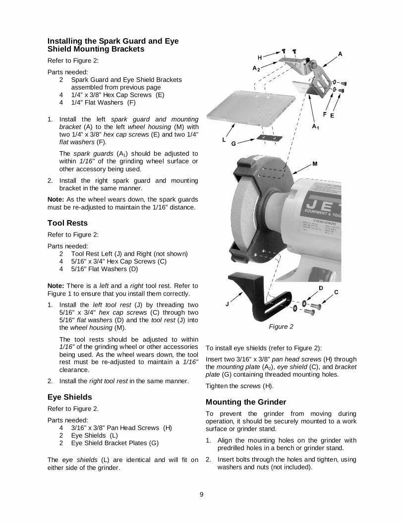
Installing the Spark Guard and Eye Shield Mounting Brackets Refer to Figure 2:
Parts needed: 2 Spark Guard and Eye Shield Brackets
assembled from previous page 4 1/4” x 3/8” Hex Cap Screws (E) 4 1/4" Flat Washers (F)
1. Install the left spark guard and mounting bracket (A) to the left wheel housing (M) with two 1/4” x 3/8” hex cap screws (E) and two 1/4" flat washers (F).
The spark guards (A1) should be adjusted to within 1/16" of the grinding wheel surface or other accessory being used.
2. Install the right spark guard and mounting bracket in the same manner.
Note: As the wheel wears down, the spark guards must be re-adjusted to maintain the 1/16" distance.
Tool Rests Refer to Figure 2:
Parts needed: 2 Tool Rest Left (J) and Right (not shown) 4 5/16" x 3/4" Hex Cap Screws (C) 4 5/16" Flat Washers (D)
Note: There is a left and a right tool rest. Refer to Figure 1 to ensure that you install them correctly.
1. Install the left tool rest (J) by threading two 5/16" x 3/4" hex cap screws (C) through two 5/16" flat washers (D) and the tool rest (J) into the wheel housing (M).
The tool rests should be adjusted to within 1/16" of the grinding wheel or other accessories being used. As the wheel wears down, the tool rest must be re-adjusted to maintain a 1/16" clearance.
2. Install the right tool rest in the same manner.
Eye Shields Refer to Figure 2.
Parts needed: 4 3/16” x 3/8” Pan Head Screws (H) 2 Eye Shields (L) 2 Eye Shield Bracket Plates (G)
The eye shields (L) are identical and will fit on either side of the grinder.
Figure 2
To install eye shields (refer to Figure 2):
Insert two 3/16” x 3/8” pan head screws (H) through the mounting plate (A2), eye shield (C), and bracket plate (G) containing threaded mounting holes.
Tighten the screws (H).
Mounting the Grinder To prevent the grinder from moving during operation, it should be securely mounted to a work surface or grinder stand.
1. Align the mounting holes on the grinder with predrilled holes in a bench or grinder stand.
2. Insert bolts through the holes and tighten, using washers and nuts (not included).

10
Electrical Electrical Requirements When connecting the bench grinder to the power source outlet, the outlet must be properly grounded to protect the operator from electrical shock.
In the event of a malfunction or breakdown, grounding provides a path of least resistance for electrical current to reduce the risk of electrical shock. This machine is equipped with an electric cord having an equipment-grounding conductor-outlet that is properly installed and grounded in accordance with all local codes and ordinances.
This grinder is equipped with a power cord. Improper connection of the equipment grounding conductor can result in a risk of electric shock. The conductor with insulation having an outer surface that is green (with or without yellow stripes) is the equipment -grounding conductor. If repair or replacement of the electric cord or plug is necessary, do not connect the equipment-grounding conductor to a live terminal.
Plug power cord into a 110-120V properly grounded outlet protected by a 14-amp fuse or circuit breaker.
Do not touch the prongs of the power cord plug when plugging or unplugging to or from an outlet.
If improperly grounded, this power tool can cause serious injury from electrical shock, particularly when used in damp locations or near plumbing. If an electrical shock occurs, there is the potential of a secondary hazard such as your hands coming in contact involuntarily with the rotating grinder.
Electrical Connections The JBG series bench grinders are rated at 120V, 1Ph. These grinders are designed for use on a circuit with an outlet that looks the one shown in Fig. A. and have a grounding prong, also shown in Fig. A. A temporary adapter (Fig. B) may be used to connect the plug to a two-prong receptacle (Fig. B) if a properly grounded outlet is not available. A temporary adapter should only be used until a properly grounded outlet can be installed by a qualified electrician. This adapter is not applicable in Canada. The green colored lug must be fastened to the cover plate screw.
Important: The adapter illustrated in Fig. B is for use only if you already have a properly grounded two-prong receptacle. Do not modify the plug provided-if it will not fit the outlet, have the proper outlet installed by a qualified electrician. Check with a qualified electrician or service personnel if the grounding instructions are not completely understood, or if in doubt as to whether the tool is properly grounded.
Before plugging into the power source, be sure that power switch is in the OFF position.
Extension Cords Use only three-wire extension cords that have three-prong grounding type plugs and three-prong receptacles that accept the tool's plug. Replace or repair damaged or worn core immediately.
USE PROPER EXTENSION CORD. Make sure your extension cord is good condition. When using an extension cord, be sure to use one heavy enough to carry the current your product will draw. An undersized cord will cause a drop in line voltage resulting in loss of power and overheating. Table 1 shows the correct size to use depending on cord length and nameplate ampere rating. If in doubt, use the next heavier gage. The smaller the gage number, the heavier the cord.
Amp Rating
Volts Total length of cord in feet
120V 240V
25 50
50 100
100 200
150 300
AWG
0 – 06 6 – 10
10 – 12 12 – 16
18 18 16 14
16 16 16 12
16 14 14
not rcmd
14 12 12
not rcmd Table 1

11
Operation A bench grinder is designed for hand-grinding operations such as sharpening chisels, screwdrivers, drill bits, removing excess metal, and smoothing metal surfaces.
A Medium Grain Abrasive Grinding Wheel is suitable for rough grinding where a considerable amount of metal must be removed or when obtaining a smooth finish is not important.
A Fine Grain Abrasive Grinding Wheel should be used for sharpening tools of grinding to close size tolerances because it removes metal more gradually for precision grinding and gives work a smooth finish.
Always use approved safety glasses or face shields! Failure to comply may cause serious injury!
Switch The switch is located on the front of the grinder near the bottom. To turn the tool on, depress the rocker switch at the top near the word ON. To turn the tool off, depress the bottom part of the rocker switch near the word OFF.
Precautions Before starting the grinder, turn the wheels by hand making sure they are clear of obstructions and that they turn freely. The tool rests and spark guards should not touch the wheel.
Turn on the grinder and allow it to reach full running speed before starting to grind.
Keep a steady, moderate pressure on the workpiece and keep it moving at an even pace for smooth grinding. Pressing too hard overheats the motor and prematurely wears down the grinding wheels. Note the original bevel angle on the item to be sharpened and try to maintain the same shape. The grinding wheel should rotate into the object being sharpened. Keep a tray filled with water and dip your work into in regularly to prevent overheating. Overheating can weaken metals.
Do not use the side of the grinding wheel; this puts dangerous stress on the wheel.
When the wheel becomes loaded or dull, use an approved grinding wheel dresser and dress the wheel face.
Keep the tool rest and spark guard to within 1/16" of the grinding wheel. See the Adjustment section to adjust.
Adjustments Eye Shield Tilt Adjustment 1. Loosen lock knob (A1, Fig. 3).
2. Adjust eye shield to the desired tilt angle (A2, Fig. 3).
Spark Guard As the wheel wears down, the spark guards must be re-adjusted to maintain a 1/16" distance.
To adjust:
1. Loosen two hex cap screws (B1, Fig. 3) with a 10mm wrench.
2. Slide the spark guard (B2, Fig. 3) to 1/16" distance from the grinding wheel surface.
3. Tighten screw (B1, Fig. 3).
Figure 3
Tool Rest As the wheel wears down, the tool rests must be re-adjusted to maintain a 1/16" distance.
1. Loosen two hex cap screws (C1, Fig. 3) with a 12mm wrench.
2. Slide the tool rest (C2, Fig. 3) to a distance of 1/16" from the grinding wheel.
3. Tighten screws (C1, Fig. 3).

12
Maintenance For safety, turn the switch to OFF and remove plug from the power source outlet before adjusting and maintaining the bench grinder. If the power cord is worn, cut or damaged in any way, have it replaced immediately.
Ring Test Before replacing a grinding wheel, perform this simple test on the replacement wheel:
1. Loop a piece of string through the grinding wheel hole and suspend the wheel by holding up the string.
2. Tap the wheel with a piece of scrap wood or a wooden dowel.
A good wheel will "ring"; a defective wheel will "thud". Discard any wheel that does not "ring". An internal defect may not be apparent by visual inspection alone. The ring test may uncover an internal crack or void.
Care of Grinding Wheel In normal use, grinding wheels may become cracked, grooved, rounded at the edges, chipped, out of true or loaded with foreign material.
Cracked wheels should be replaced IMMEDIATELY. While any of the other conditions can be remedied with a dressing tool (available at most hardware stores), new wheels sometimes require dressing to make them round.
Changing Wheels If you must replace a wheel be sure to obtain one with a safe rated speed at least as high as the NO LOAD RPM marked on the grinder's nameplate. Refer to Table 2 to determine correct dimensions for the replacement wheel.
Model Wheel Diameter
Maximum Width
Center Hole
JBG-6A 6" 3/4" 1/2"
JBG-8A 8" 3/4" 5/8"
JBG-10A 10" 1" 1"
Table 2
Your bench grinder will accept most polishing and buffing wheels available at dealers and hardware stores.
The use of any other accessory is not recommended and may result in serious injury!
To change a wheel (refer to Figure 4):
1. Disconnect grinder from the power source.
2. Loosen the spark guard (A) and tool rest (B) (refer to the Adjustment section on page 11) and move the spark guard and tool rest away from the wheel.
3. Remove the guard cover using a Phillips or flathead screwdriver.
4. Stabilize the wheel by holding the opposite wheel firmly.
5. Unscrew the wheel nut (C) with a 1" wrench.
Note: Turn the locking nut on the right-hand wheel counterclockwise to loosen. Turn the locking nut on the left-hand wheel clockwise to loosen.
6. Remove the outer flange (D) and wheel (E).
7. Clean flanges. Check the flanges to make sure they are flat. Wheel flanges that are not flat will cause the wheel to wobble.
8. Put the inner flange, wheel (E), outer flange (D) and nut (C) on the shaft. Tighten the nut. Do not over tighten. This may cause the wheel to crack.
9. Replace the guard cover. Adjust the spark guards and tool rests to a 1/16" clearance from the wheel (see Adjustments on page 11).
Figure 4

13
Grinding Wheels The JET Series bench grinders come equipped with general purpose grinding wheels. Wheels vary according to types of abrasive, hardness, grit size, and structure. JET carries a full line of abrasive grinding, carbide grinding, tool sharpening, and wire wheels. Contact your local distributor for the proper grinding wheel or wire wheel brush for your application.
Wire Wheel Brushes Wire brushing provides a fast way to remove rust scale, burrs, and point from metal. Use coarse wire brushes for hard cleaning jobs. Use fine wire brushes for polishing and finish work. When the brush tips become dull, reverse the brush on the grinder.
Cleaning
Metal shavings may still be hot from recent grinding operations. Make sure shavings and debris are cold before cleaning the grinder.
Brush all shavings from the motor housing, tool rests, and wheel guards. Check grinding wheels for cracks and chips. Replace if damaged.
Avoid the use of the following cleaning chemicals or solvents: gasoline, carbon tetrachloride, chlorinated solvents, ammonia and household detergents containing ammonia.
Lubrication All motor bearings are permanently lubricated at the factory and require no additional lubrication.

14
Troubleshooting Problem Probable Cause Remedy
Motor will not start
Not plugged into receptacle Plug it into the power source receptacle
Switch not in the ON position Turn the switch to the ON position
Motor cord cut or abraded Replace with a new cord
Plug on cord is faulty Replace with a new plug
Fuse or circuit breaker open Re-set, may be too many machines on line
Motor faulty Call Walter Meier Customer Service Department
Motor will not start and fuse or circuit breaker opens
Too many electrical machines running on the same outlet
Turn off other machines and try again
Incorrect fuse Try time delay fuse, or go to circuit with higher rated fuse of circuit breaker
Wheels cannot rotate because of obstruction
Unplug and turn grinding wheel by hand
Undersized extension cord Use correct size extension cord; see manual
Short circuit Cord, plug, or motor need repair; call Walter Meier Customer Service Dept.
Motor fails to develop full power
Low line voltage Check power line for proper voltage
Faulty motor or capacitor Call Walter Meier Customer Service Dept.
Motor overheats
Overload on motor Reduce load to motor; do not press so hard
Poor ventilation for motor Unplug and clean out around motor; provide better air circulation
Capacitor failure Call Walter Meier Customer Service Dept.
Motor stalls or slows
Motor overload Reduce load to motor; do not press so hard
Low line voltage Check power line for proper voltage
Loose wire connections Call Walter Meier Customer Service Dept.
Faulty motor Call Walter Meier Customer Service Dept.
Frequent fuse or circuit breaker failure
Motor overload Reduce load to motor; do not press so hard
Overload of electrical circuit Too many electrical appliances on same circuit
Incorrect fuse of circuit breaker Have electrician upgrade service to outlet

15
Parts and Assembly for JBG Series Grinders Parts List
Index No Part No Description Size Qty 1 .............. JBG6A-02P .............Shaft and Rotor Assembly ................................................................... 1 ................ JBG8A-02P .............Shaft and Rotor Assembly ................................................................... 1 ................ JBG10A-02P ...........Shaft and Rotor Assembly ................................................................... 1 3 .............. JBG6A-03 ...............Stator Assembly ................................................................................. 1 ................ JBG8A-03 ...............Stator Assembly ................................................................................. 1 ................ JBG10A-03..............Stator Assembly ................................................................................. 1 5 .............. JBG6A-05W ............Motor Housing .................................................................................... 1 ................ JBG8A-05W ............Motor Housing .................................................................................... 1 ................ JBG10A-05W ..........Motor Housing .................................................................................... 1 6 .............. JBG6A-06W ............Base .................................................................................................. 1 ................ JBG8A-06W ............Base .................................................................................................. 1 ................ JBG10A-06W ..........Base .................................................................................................. 1 7 .............. JBG6A-07 ...............Cross Screw ....................................................1/4 x 7/8 ..................... 4 ................ JBG10A-07..............Cross Screw .....................................................5/16 x 1 ...................... 4 8 .............. TS-0720071 ............Lock Washer…………………………………………1/4……………………..4 ................ TS-0720081 ............Lock Washer ....................................................5/16 ........................... 4 9 .............. TS-0561011 ............Hex Nut............................................................1/4 ............................. 4 ................ TS-0570021 ............Hex Nut............................................................5/16 ........................... 4 10 ............ JBG6A-10 ...............Fan .................................................................................................... 1 ................ JBG8A-10 ...............Fan .................................................................................................... 1 ................ JBG10A-10..............Fan .................................................................................................... 1 11 ............ BB-6202ZZ ..............Ball Bearing (JBG-6A) ......................................................................... 2 ................ BB-6204ZZ ..............Ball Bearing (JBG-8A) ......................................................................... 2 ................ BB-6206ZZ ..............Ball Bearing (JBG-10A) ....................................................................... 1 12 ............ JBG6A-12W ............Cover ................................................................................................. 2 ................ JBG8A-12W ............Cover ................................................................................................. 2 ................ JBG10A-12W ..........Cover ................................................................................................. 2 ................ JBG10A-14..............Flat Washer (JBG-10A only – not shown) ............................................. 4 15 ............ JBG6A-15 ...............Screw ..............................................................3/16 x 5/8. .................. 4 ................ JBG10A-15..............Screw ..............................................................1/4 x 7/8 ..................... 4 16 ............ JBG6A-16P .............Inner Wheel Guard - left ...................................................................... 1 ................ JBG8A-16P .............Inner Wheel Guard - left ...................................................................... 1 ................ JBG10A-16..............Inner Wheel Guard - left ...................................................................... 1 17 ............ JBG6A-17P .............Inner Wheel Guard - right .................................................................... 1 ................ JBG8A-17P .............Inner Wheel Guard - right .................................................................... 1 ................ JBG10A-17..............Inner Wheel Guard - right .................................................................... 1 ................ JBG10A-18..............Flat Washer (JBG-10A only – not shown) ............................................. 4 19 ............ JBG6A-19 ...............Cross Screw…………………………………………1/4 x 1/2………………..4 20 ............ JBG6A-20 ...............Wheel Flange ...................................................1/2 I.D ........................ 4 ................ JBG8A-20 ...............Wheel Flange ...................................................5/8 I.D ........................ 4 ................ JBG10A-20..............Wheel Flange ...................................................1 I.D........................... 4 21 ............ 576208....................Grinding Wheel……………………………………..6” x 3/4", 46 grit ........... 1 ................ 576220....................Grinding Wheel……………………………………..8” x 3/4", 46 grit ........... 1 ................ 576228....................Grinding Wheel……………………………………10” x 1”, 46 grit.............. 1 21A.......... 576206....................Grinding Wheel……………………………………..6” x 3/4", 24 grit ........... 1 ................ 576219....................Grinding Wheel……………………………………..8” x 3/4", 24 grit ........... 1 ................ 576226....................Grinding Wheel…………………………………….10” x 1”, 24 grit............. 1 22 ............ JBG6A-22 ...............Nut - left hand thread ........................................1/2 ............................. 1 ................ JBG8A-22 ...............Nut - left hand thread ........................................5/8 ............................. 1 ................ JBG10A-22..............Nut - left hand thread .......................................................................... 1 23 ............ JBG6A-23 ...............Nut - right hand thread ......................................1/2 ............................. 1 ................ JBG8A-23 ...............Nut - right hand thread ......................................5/8 ............................. 1 ................ JBG10A-23..............Nut - right hand thread ........................................................................ 1

16
Parts List
Index No Part No Description Size Qty
24 ............ JBG6A-24P .............Outer Wheel Guard - left ..................................................................... 1 ................ JBG8A-24P .............Outer Wheel Guard - left ..................................................................... 1 ................ JBG10A-24..............Outer Wheel Guard - left ..................................................................... 1 25 ............ JBG6A-25P .............Outer Wheel Guard - right ................................................................... 1 ................ JBG8A-25P .............Outer Wheel Guard - right ................................................................... 1 ................ JBG10A-25..............Outer Wheel Guard - right ................................................................... 1 26 ............ JBG6A-26 ...............Cross Screw .....................................................1/4 x 1/2 ..................... 8 27 ............ JBG6A-27 ...............Tool Rest - left .................................................................................... 1 ................ JBG8A-27 ...............Tool Rest - left .................................................................................... 1 ................ JBG10A-27..............Tool Rest - left .................................................................................... 1 28 ............ JBG6A-28 ...............Tool Rest - right .................................................................................. 1 ................ JBG8A-28 ...............Tool Rest - right .................................................................................. 1 ................ JBG10A-28..............Tool Rest - right .................................................................................. 1 29 ............ TS-0680031 ............Flat Washer......................................................5/16 ........................... 4 30 ............ TS-0051031 ............Hex Cap Bolt ....................................................5/16 x 3/4 ................... 4 31 ............ JBG6A-31 ...............Rubber Guide ..................................................................................... 1 ................ JBG8A-31 ...............Rubber Guide ..................................................................................... 1 ................ JBG10A-31..............Rubber Guide ..................................................................................... 1 32 ............ JBG6A-32 ...............Cord Plate .......................................................................................... 1 ................ JBG8A-32 ...............Cord Plate .......................................................................................... 1 ................ JBG10A-32..............Cord Plate .......................................................................................... 1 ................ JBG10A-33..............Star Washer (JBG-10A only – not shown) ............................................ 2 34 ............ JBG6A-34 ...............Cross Screw .....................................................3/16 x 1/4 ................... 2 35 ............ JBG6A-35 ...............Condenser (125 VAC, 100MFD) .......................................................... 1 ................ JBG8A-35 ...............Condenser (125 VAC, 200MFD) .......................................................... 1 ................ JBG10A-35..............Condenser (125 VAC, 300MFD) .......................................................... 1 36 ............ JBG6A-36 ...............Bracket .............................................................................................. 1 ................ JBG8A-36 ...............Bracket .............................................................................................. 1 ................ JBG10A-36..............Bracket .............................................................................................. 1 38 ............ JBG6A-38 ...............Screw ..............................................................3/16 x 1/4 ................... 1 39 ............ JBG6A-39 ...............Power Cord ........................................................................................ 1 ................ JBG8A-39 ...............Power Cord ........................................................................................ 1 ................ JBG10A-39..............Power Cord ........................................................................................ 1 40 ............ JBG6A-40 ...............Cross Screw .....................................................3/16 x 3/8 ................... 1 41 ............ JBG6A-41 ...............Star Washer .....................................................3/16 ........................... 1 42 ............ JBG6A-42 ...............Clip .................................................................................................... 1 ................ JBG8A-42 ...............Clip .................................................................................................... 1 ................ JBG10A-42..............Clip .................................................................................................... 1 ................ JBG10A-43..............Hex Nut (JBG-10A only – not shown) ................................................... 2 44 ............ JBG6A-44 ...............Switch ................................................................................................ 1 ................ JBG8A-44 ...............Switch ................................................................................................ 1 ................ JBG10A-44..............Switch (w/ JBG10A-45) ....................................................................... 1 45 ............ JBG6A-45 ...............Switch Plate ....................................................................................... 1 ................ JBG8A-45 ...............Switch Plate ....................................................................................... 1 ................ JBG10A-45..............Switch Plate (re:JBG10A-44) ............................................................... 1 46 ............ JBG6A-46 ...............Screw ..............................................................3/16 x 1/4 ................... 2 47 ............ JBG6A-47 ...............Base Plate ......................................................................................... 1 ................ JBG8A-47 ...............Base Plate ......................................................................................... 1 ................ JBG10A-47..............Base Plate ......................................................................................... 1 49 ............ JBG6A-49 ...............Cross Screw .....................................................3/16 x 1/2 ................... 4 ................ JBG8A-49 ...............Cross Screw .....................................................3/16 x 1/2 ................... 4 ................ JBG10A-49..............Cross Screw .....................................................1/4 x 1/2 ..................... 4 50 ............ JBG6A-50 ...............Eye Shield Plate - left. ......................................................................... 1 ................ JBG8A-50 ...............Eye Shield Plate - left. ......................................................................... 1 ................ JBG10A-50..............Eye Shield Plate - left. ......................................................................... 1

17
Parts List
Index No Part No Description Size Qty
51 ............ JBG6A-51 ...............Eye Shield Plate - right. ....................................................................... 1 ................ JBG8A-51 ...............Eye Shield Plate - right. ....................................................................... 1 ................ JBG10A-51..............Eye Shield Plate - right. ....................................................................... 1 52 ............ TS-0720071 ............Lock Washer ....................................................1/4 ............................. 2 53 ............ TS-0680021 ............Flat Washer......................................................1/4 ............................. 6 54 ............ JBG6A-54 ...............Cross Screw .....................................................1/4 x 1/2 ..................... 2 ................ JBG8A-54 ...............Cross Screw .....................................................1/4 x 1/2 ..................... 2 ................ JBG10A-54..............Screw ................................................................................................ 4 54A.......... JBG6A-54 ...............Cross Screw .....................................................1/4 x 3/8 ..................... 4 55 ............ JBG6A-55 ...............Eye Shield Plate - left .......................................................................... 1 ................ JBG8A-55 ...............Eye Shield Plate - left .......................................................................... 1 ................ JBG10A-55..............Eye Shield Plate - left .......................................................................... 1 56 ............ JBG6A-56 ...............Eye Shield Plate - right. ....................................................................... 1 ................ JBG8A-56 ...............Eye Shield Plate - right. ....................................................................... 1 ................ JBG10A-56..............Eye Shield Plate - right. ....................................................................... 1 57 ............ JBG6A-57 ...............Lock Hub (JBG-6A/8A) ......................................1/4 ............................. 2 58 ............ JBG6A-58 ...............Cross Screw .....................................................3/16 x 3/8 ................... 4 59 ............ JBG6A-59 ...............Eye Shield.......................................................................................... 2 ................ JBG6A-59A .............Eye Shield Assembly .......................................................................... 2 ................ JBG8A-59 ...............Eye Shield ......................................................................................... 2 ................ JBG8A-59A .............Eye Shield Assembly .......................................................................... 2 ................ JBG10A-59..............Eye Shield ......................................................................................... 2 ................ JBG10A-59A ...........Eye Shield Assembly .......................................................................... 2 60 ............ JBG6A-60 ...............Eye Shield Bracket Plate ..................................................................... 2 ................ JBG10A-60..............Eye Shield Bracket Plate ..................................................................... 2 61 ............ JBG6A-61 ...............Identification Label .............................................................................. 1 ................ JBG8A-61 ...............Identification Label .............................................................................. 1 ................ JBG10A-61..............Identification Label .............................................................................. 1 63 ............ JBG6A-63 ...............Direction Label ................................................................................... 2 64 ............ JBG6A-64 ...............Rubber Foot (6A/8A) ........................................................................... 4 ................ JBG10A-64..............Rubber Foot ....................................................................................... 4 65 ............ JBG6A-65 ...............Switch Seat ........................................................................................ 1 ................ JBG8A-65 ...............Switch Seat ........................................................................................ 1 ................ JBG10A-65..............Switch Seat ........................................................................................ 1 66 ............ JBG6A-66 ...............Centrifugal Start Switch ....................................................................... 1 ................ JBG8A-66 ...............Centrifugal Start Switch ....................................................................... 1 ................ JBG10A-66..............Centrifugal Start Switch ....................................................................... 1

18
Assembly Drawing

19
Wiring Diagram

20
Ordering Replacement Parts To order parts or reach our service department, call 1-800-274-6848, Monday through Friday (see our website for business hours, www.waltermeier.com). Having the Model Number and Serial Number of your machine available when you call will allow us to serve you quickly and accurately.
WALTER MEIER (Manufacturing), Inc. 427 New Sanford Road
LaVergne, Tennessee 37086 Phone: 800-274-6848
www.waltermeier.com