operating instructions and parts manual bench top...
TRANSCRIPT

Operating Instructions and Parts Manual Bench Top Edge Bander Model JEB-1
(veneer banding not included)
WMH TOOL GROUP
2420 Vantage Drive Elgin, Illinois 60123 Part No. M-708000 Ph.: 800-274-6848 Revision B 12/04 www.wmhtoolgroup.com Copyright © WMH Tool Group

2
This manual has been prepared for the owner and operators of a JET Model JEB-1 Edge Bander. Its purpose, aside from machine operation, is to promote safety using accepted operating and maintenance procedures. To obtain maximum life and efficiency from your Edge Bander and to aid in using it safely, please read this manual thoroughly and follow the instructions carefully.
Warranty and Service WMH Tool Group warrants every product it sells. If one of our tools needs service or repair, one of our Authorized Repair Stations located throughout the United States can provide quick service or information.
In most cases, a WMH Tool Group Repair Station can assist in authorizing repair work, obtaining parts, or perform routine or major maintenance repair on your JET product.
For the name of an Authorized Repair Station in your area, please call 1-800-274-6848, or visit our web site at www.wmhtoolgroup.com
More Information
Remember, WMH Tool Group is consistently adding new products to the line. For complete, up-to-date product information, check with your local WMH Tool Group distributor, or visit our web site at www.wmhtoolgroup.com
WMH Tool Group Warranty
WMH Tool Group makes every effort to assure that its products meet high quality and durability standards and warrants to the original retail consumer/purchaser of our products that each product be free from defects in materials and workmanship as follows: 1 YEAR LIMITED WARRANTY ON ALL PRODUCTS UNLESS SPECIFIED OTHERWISE. This Warranty does not apply to defects due directly or indirectly to misuse, abuse, negligence or accidents, normal wear-and-tear, repair or alterations outside our facilities, or to a lack of maintenance.
WMH TOOL GROUP LIMITS ALL IMPLIED WARRANTIES TO THE PERIOD SPECIFIED ABOVE, BEGINNING FROM THE DATE THE PRODUCT WAS PURCHASED AT RETAIL. EXCEPT AS STATED HEREIN, ANY IMPLIED WARRANTIES OR MERCHANTABILITY AND FITNESS ARE EXCLUDED. SOME STATES DO NOT ALLOW LIMITATIONS ON HOW LONG THE IMPLIED WARRANTY LASTS, SO THE ABOVE LIMITATION MAY NOT APPLY TO YOU. IN NO EVENT SHALL WMH TOOL GROUP BE LIABLE FOR DEATH, INJURIES TO PERSONS OR PROPERTY, OR FOR INCIDENTAL, CONTINGENT, SPECIAL, OR CONSEQUENTIAL DAMAGES ARISING FROM THE USE OF OUR PRODUCTS. SOME STATES DO NOT ALLOW THE EXCLUSION OR LIMITATION OF INCIDENTAL OR CONSEQUENTIAL DAMAGES, SO THE ABOVE LIMITATION OR EXCLUSION MAY NOT APPLY TO YOU.
To take advantage of this warranty, the product or part must be returned for examination, postage prepaid, to an Authorized Repair Station designated by our office. Proof of purchase date and an explanation of the complaint must accompany the merchandise. If our inspection discloses a defect, we will either repair or replace the product at our discretion, or refund the purchase price if we cannot readily and quickly provide a repair or replacement. We will return the repaired product or replacement at WMH Tool Group’s expense, but if it is determined there is no defect, or that the defect resulted from causes not within the scope of WMH Tool Group’s warranty, then the user must bear the cost of storing and returning the product. This warranty gives you specific legal rights; you may also have other rights, which vary from state to state.
WMH Tool Group sells through distributors only. Members of the WMH Tool Group reserve the right to effect at any time, without prior notice, alterations to parts, fittings and accessory equipment, which they may deem necessary for any reason whatsoever.

3
Table of Contents Warranty and Service ..............................................................................................................................2 Warning...................................................................................................................................................4 Introduction..............................................................................................................................................6 Description ..............................................................................................................................................6 Specifications ..........................................................................................................................................6 Unpacking ...............................................................................................................................................7
Contents of the Shipping Container ......................................................................................................7 Assembly.................................................................................................................................................8
Installing Support Table........................................................................................................................8 Grounding Instructions.............................................................................................................................8
Extension Cords...................................................................................................................................8 Adjustments.............................................................................................................................................9
Upper and Lower Guides......................................................................................................................9 Infeed and Outfeed Fences ..................................................................................................................9
Operating Controls.................................................................................................................................10 Operation...............................................................................................................................................10
Selection of Banding Material .............................................................................................................10 Basic Procedure.................................................................................................................................10
Maintenance..........................................................................................................................................13 Main Table Replacement....................................................................................................................13
Troubleshooting the JEB-1 Edge Bander ...............................................................................................14 Replacement Parts ................................................................................................................................15
Parts List: JEB-1 Edge Bander ...........................................................................................................16 JEB-1 Edge Bander............................................................................................................................17

4
Warning
1. Read and understand the entire owners manual before attempting assembly or operation.
2. Read and understand the warnings posted on the machine and in this manual. Failure to comply with all of these warnings may cause serious injury.
3. Replace the warning labels if they become obscured or removed.
4. This edge bander is designed and intended for use by properly trained and experienced personnel only. If you are not familiar with the proper and safe operation of an edge bander, do not use until proper training and knowledge have been obtained.
5. Do not use this edge bander for other than its intended use. If used for other purposes, WMH Tool Group disclaims any real or implied warranty and holds itself harmless from any injury or tool damage that may result from that use.
6. Some dust created by power sanding, sawing, grinding, drilling and other construction activities contain chemicals known to cause cancer, birth defects or other reproductive harm. Some examples of these chemicals are:
• Lead from lead based paint.
• Crystalline silica from bricks, cement and other masonry products.
• Arsenic and chromium from chemically treated lumber.
Your risk of exposure varies, depending on how often you do this type of work. To reduce your exposure to these chemicals, work in a well-ventilated area and work with approved safety equipment, such as face or dust masks that are specifically designed to filter out microscopic particles.
7. Do not operate this machine while tired or under the influence of drugs, alcohol or any medication.
8. Make certain the switch is in the OFF position before connecting the machine to the power supply.
9. Make all machine adjustments or maintenance with the machine unplugged from the power source.
10. Remove adjusting keys and wrenches. Form a habit of checking to see that keys and adjusting wrenches are removed from the machine before turning it on.
11. Keep safety guards in place at all times when the machine is in use. If removed for maintenance purposes, use extreme caution and replace the guards immediately.
12. Check damaged parts. Before further use of the machine, a guard or other part that is damaged should be carefully checked to determine that it will operate properly and perform its intended function. Check for alignment of moving parts, binding of moving parts, breakage of parts, mounting and any other conditions that may affect its operation. A guard or other part that is damaged should be properly repaired or replaced.
13. Provide for adequate space surrounding work area and non-glare, overhead lighting.
14. Keep the floor around the tool clean and free of scrap material, oil and grease.
15. Keep visitors a safe distance from the work area. Keep children away.ah
16. Make your workshop child proof with padlocks, master switches or by removing starter keys.
17. Give your work undivided attention. Looking around, carrying on a conversation and “horse-play” are careless acts that can result in serious injury.
18. Maintain a balanced stance at all times so that you do not fall or lean against the heat gun. Do not overreach or use excessive force to perform any tool operation.

5
19. Use the right tool at the correct speed and feed rate. Do not force a tool or attachment to do a job for which it was not designed. The right tool will do the job better and safer.
20. Use recommended accessories; improper accessories may be hazardous.
21. Maintain tools with care. Keep cutting blades sharp and clean for the best and safest performance. Follow instructions for lubricating and changing accessories.
22. Never leave the tool running unattended.
23. Remove loose items and unnecessary work pieces from the area before starting the tool.
Familiarize yourself with the following safety notices used in this manual:
This means that if precautions are not heeded, it may result in minor injury and/or possible machine damage.
This means that if precautions are not heeded, it may result in serious injury or possibly even death.
- - SAVE THESE INSTRUCTIONS - -

6
Introduction This manual is provided by JET covering the safe operation and maintenance procedures for a Model JEB-1 Edge Bander. This manual contains instructions on installation, safety precautions, general operating procedures, maintenance instructions and parts breakdown. This tool has been designed and constructed to provide years of trouble free operation if used in accordance with instructions set forth in this manual. If there are any questions or comments, please contact either your local supplier or WMH Tool Group. WMH Tool Group can also be reached at our web site: www.wmhtoolgroup.com.
Description The Edge Bander is simple to operate and is designed to handle wood and polyester edge banding materials that are backed by a hot melt adhesive. It has non-skid rubber feet, a built-in plunge cutting knife and wide support table for the banding material roll. The heating element has infinite adjustment within the 100 to 200 degree heating range. The adjustable guides will accomodate banding materials as wide as 2-1/4”.
Specifications Model Number ................................................................................................................................. JEB-1 Stock Number................................................................................................................................ 708000 Laminated Table Size (L x W)(in.) ...................................................................................... 26-3/4 x 7-9/16 Fence Height (in.) ............................................................................................................................ 2-3/16 Overall Size (L x W x H)(in.)....................................................................................26-3/4 x 26-1/4 x 9-3/8 Banding Material Maximum Width (in.) ...............................................................................................2-1/4 Operating Temperature Range (deg.) ....................................................................................... 100 to 200 Hot Air Gun.....................................................................................Double Insulated, 1500W, 120V, 60Hz Approximate Net Weight (lbs.) ............................................................................................................... 26
The above specifications were current at the time this manual was published, but because of our policy of continuous improvement, WMH Tool Group reserves the right to change specifications at any time and without prior notice, without incurring obligations.

7
Unpacking Open shipping container and check for shipping damage. Report any damage immediately to your distributor and shipping agent. Do not discard any shipping material until the Edge Bander is assembled and running properly.
Compare the contents of your container with the following parts list to make sure all parts are intact. Missing parts, if any, should be reported to your distributor. Read the instruction manual thoroughly for assembly, maintenance and safety instructions.
Contents of the Shipping Container 1 Edge Bander 1 Support Table
1 Stud 1 Hex Cap Screw, M8 x 100 (with hex nut)
2 Socket Head Cap Screws, M6 x 10 2 Flat Washers, M6 1 Hex Wrench, 5mm
1 Double Edge Trimmer 1 Owner's Manual
1 Warranty Card
Read and understand the entire contents of this manual before attempting set-up
or operation! Failure to comply may cause injury.

8
Assembly Tools required for assembly:
5mm hex wrench (provided)
Installing Support Table 1. Tilt the Edge Bander up and attach the
support table to the two holes at the rear of the Edge Bander, with two M6 x 10 socket head cap screws and two M6 flat washers. See Figure 1. Tighten with the 5mm hex wrench.
2. From below the support table, insert the M8 x 100 hex cap screw up through the hole in the center of the support table as shown in Figure 2. (The hex nut on the screw should be below the support table.)
3. Place the stud, with its threaded opening facing down, over the hex cap screw and thread it down onto the hex cap screw. See Figure 2.
4. Adjust the M8 x 100 screw until its head contacts the surface of your table or bench. This enables the screw to act as a support for the support table.
5. Secure the position of the M8 x 100 screw by tightening the hex nut up against the bottom of the support table.
Grounding Instructions Make sure the voltage of your power supply matches the specifications on the label affixed to the heat gun. The Edge Bander is designed to run on standard 120 volt “household” current.
Extension Cords If an extension cord is necessary, make sure the cord rating is suitable for the amperage listed on the machine's motor plate. An undersize cord will cause a drop in line voltage resulting in loss of power and overheating.
The chart in Figure 3 shows the correct size cord to use based on cord length and motor plate amp rating. If in doubt, use the next heavier gauge. The smaller the gauge number the heavier the cord.
Figure 1
Figure 2
Recommended Gauges (AWG) of Extension Cords
Extension Cord Length *
Amps 25 feet
50 feet
75 feet
100 feet
150 feet
200 feet
< 5 16 16 16 14 12 12
5 to 8 16 16 14 12 10 NR
8 to 12 14 14 12 10 NR NR
12 to 15 12 12 10 10 NR NR
15 to 20 10 10 10 NR NR NR
21 to 30 10 NR NR NR NR NR
*based on limiting the line voltage drop to 5V at 150% of the rated amperes.
NR: Not Recommended.
Figure 3
9
Adjustments
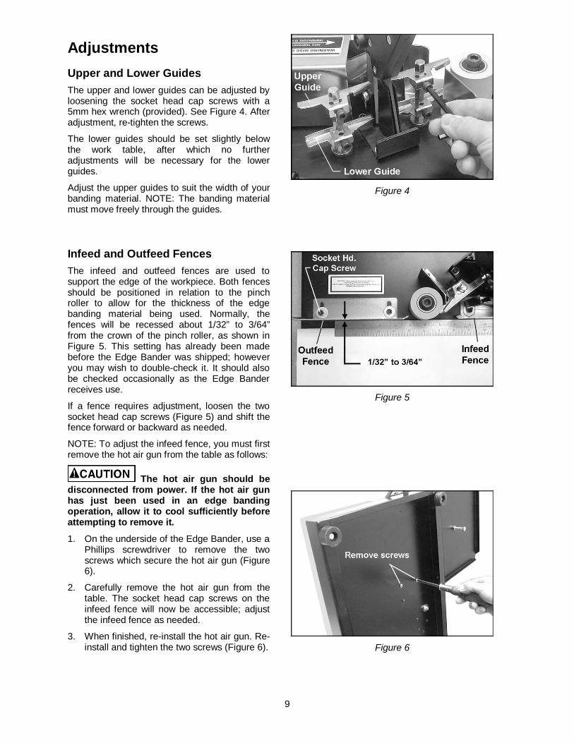
Upper and Lower Guides The upper and lower guides can be adjusted by loosening the socket head cap screws with a 5mm hex wrench (provided). See Figure 4. After adjustment, re-tighten the screws.
The lower guides should be set slightly below the work table, after which no further adjustments will be necessary for the lower guides.
Adjust the upper guides to suit the width of your banding material. NOTE: The banding material must move freely through the guides.
Infeed and Outfeed Fences The infeed and outfeed fences are used to support the edge of the workpiece. Both fences should be positioned in relation to the pinch roller to allow for the thickness of the edge banding material being used. Normally, the fences will be recessed about 1/32” to 3/64” from the crown of the pinch roller, as shown in Figure 5. This setting has already been made before the Edge Bander was shipped; however you may wish to double-check it. It should also be checked occasionally as the Edge Bander receives use.
If a fence requires adjustment, loosen the two socket head cap screws (Figure 5) and shift the fence forward or backward as needed.
NOTE: To adjust the infeed fence, you must first remove the hot air gun from the table as follows:
The hot air gun should be disconnected from power. If the hot air gun has just been used in an edge banding operation, allow it to cool sufficiently before attempting to remove it.
1. On the underside of the Edge Bander, use a Phillips screwdriver to remove the two screws which secure the hot air gun (Figure 6).
2. Carefully remove the hot air gun from the table. The socket head cap screws on the infeed fence will now be accessible; adjust the infeed fence as needed.
3. When finished, re-install the hot air gun. Re-install and tighten the two screws (Figure 6).
Figure 4
Figure 5
Figure 6

10
Operating Controls The main on-off switch is on the handle of the hot air gun (Figure 7).
The temperature of the heat is controlled by the dial (Figure 7); hotter toward the red part of the dial, cooler toward the blue part of the dial.
NOTE: The heat setting is arbitrary. The hotter the gun, the faster you must feed the work. For best results, start with a low heat and make adjustments according to your experience with the edge bander and the material you are using.
Operation
Selection of Banding Material The edge banding material must have a hot melt adhesive backing.
The width of the edge banding material you select is dependent upon the thickness of the stock you are banding. The Edge Bander will accept banding material up to 2-1/4” wide.
The banding material is usually no more than 1/16” wider than the thickness of the workpiece. This means there is only about 1/32” of excess to remove from either side of the workpiece. See Figure 8. This allows the excess to be removed with a knife (not provided) or the double edge trimmer. The excess may also be removed by sanding.
When the edge banding material is too wide, the clean-up job becomes difficult and edge banding material is wasted.
Basic Procedure 1. Set the roll of edge banding material on the
support table. The banding material should be oriented so the adhesive backed side will face the heat gun as it moves through the guides.
2. Make sure the lower guides have been set slightly below the work table. This will place the bottom edge of the banding material slightly below the edge of the workpiece.
3. Slide the leading end of the banding material through the guides, and adjust the upper guides to the width of the banding material. See Figure 9. NOTE: The banding material must move freely through the guides.
Figure 7
Figure 8
(banding shown is 13/16” wide oak veneer)
Figure 9

11
4. Position the leading end of the banding material in front of the nozzle of the hot air gun, as shown in Figure 10.
5. Choose the desired heat setting on the temperature dial.
6. Plug the Edge Bander into the power source and turn on the switch. Allow approximately 30 seconds for the hot air gun to reach operating temperature. Adjust the temperature dial again if necessary.
The hot air gun generates sufficient heat to burn flesh and ignite combustibles. Work with extreme caution. Do not touch metal areas around hot air gun while it is turned on.
7. As the hot melt adhesive softens at the front end of the banding material, hand feed the banding material up to the crown of the pinch roller, as shown in Figure 11.
NOTE: A general indicator that the adhesive is hot enough is when it begins to bubble slightly.
8. Place the workpiece on the table and against the infeed fence. See Figure 12.
9. Push the edge of the workpiece along the infeed fence and against the edge banding material (Figure 12). The edge banding material will be trapped between the pinch roller and the workpiece. The edge banding material will bond to the workpiece.
10. Guide the workpiece along the pinch roller at a steady, moderate speed. The edge banding material will continue to bond to the edge of the workpiece and will be pulled through the guides by the movement of the workpiece.
NOTE: Be sure the hot melt adhesive is bonding to the workpiece. If you feed the workpiece too fast, or the hot air gun temperature is set too low, the bond will be poor. Make adjustments as needed to obtain a good bond.
Figure 10
Figure 11
Figure 12

12
11. As the workpiece is advanced (Figure 13), the leading edge of the workpiece may be rested against the outfeed fence as well as the pinch roller. Always maintain pressure on the pinch roller while you are edge banding.
12. When the trailing end of the workpiece lines up with the scribed mark on the infeed fence, push down on the plunge cutter firmly and rapidly to sever the edge banding material. See Figure 14.
13. Continue to push the workpiece forward until the entire edge of the workpiece has been banded. The end of the banding material will extend slightly beyond the trailing end of the workpiece.
14. Shut off the hot air gun and allow it to cool completely before storing the Edge Bander. When the Edge Bander is not being used, unplug it from the power source.
15. Trim the excess banding material from the workpiece. This can be done easily with the Double Edge Trimmer provided with your Edge Bander. See Figure 15.
16. The Double Edge Trimmer will work on materials 1/2” to 1” thick. Simply place the Trimmer over the banded edge of the workpiece and squeeze the Trimmer firmly to clamp it against the workpiece edge. Continue to squeeze it firmly, and slide the Trimmer down the edge of the workpiece in the direction of the arrows, as shown in Figure 15. Use steady, even pressure for best results.
17. Replacement knives (Stock No. JEB-151) are available for the Double Edge Trimmer. To order, contact your local distributor or call customer service at 1-800-274-6848.
18. A sharp knife (not provided), as shown in Figure 16, is an alternative method for trimming the excess banding material. The excess may also be sanded off in some cases.
Figure 13
Figure 14
Figure 15
Figure 16

13
Maintenance
Before doing maintenance on the Edge Bander, unplug it from the power source, unless specified otherwise.
Prolonged use of the Edge Bander may cause accumulation of hot melt adhesive on the guides, which can block free movement of the edge banding material. To remove this adhesive, plug in the tool and turn it on, with the heat gun at a medium setting. Keep hands away from hot air gun. As the heat gun softens the hot melt adhesive, peel the adhesive from the guides with a putty knife. Be careful not to scratch the guides; they must remain smooth for best results.
If the pinch roller needs cleaning, wipe it with soap and water. Do not use solvents on the pinch roller.
If the power cord is worn, cut, or damaged in any way, have it replaced immediately.
Main Table Replacement The laminated front table may eventually become scuffed with use. It can be replaced with any smooth faced stock. Remove the old table by unscrewing and removing the two socket head flat screws, shown in Figure 16, with a 5/32” (or 4mm) hex wrench (not provided). Use the old table as a pattern for cutting the new one.
A plastic laminate face may be glued to the new table. This will increase its durability and reduce friction between the table and the workpiece. Be sure the new table is the same thickness as the original. Make an allowance for the plastic laminate if you plan to laminate your new work table.
Figure 16

14
Troubleshooting the JEB-1 Edge Bander Trouble Probable Cause Remedy
Not connected to power source. Check plug connection.
Fuse blown, or circuit breaker tripped. Replace fuse, or reset circuit breaker.
Cord damaged. Replace cord.
Edge Bander will not turn on.
Hot air gun motor damaged. Have hot air gun repaired or replaced.
Temperature dial not set properly. Turn temperature dial toward the red. Edge Bander will not heat. Hot air gun motor damaged. Have hot air gun repaired or replaced.
Guides not adjusted properly. Position guides according to width of edge banding material. [page 9]
Edge banding material does not feed smoothly through guides. Guides need cleaning. Follow instructions for cleaning off old
adhesive from guides. [page 13]
Hot air gun not hot enough. Turn temperature dial toward the red to increase heat.
Feed rate too fast for heat level. Reduce feed rate, or increase heat level.
Infeed and/or outfeed fence not set properly.
Fences should be recessed 1/32” to 3/64” from crown of pinch roller. [page 9]
Edge banding material will not bond to workpiece.
Edge banding material does not have hot melt backing, or has poor adhesive or is defective.
Replace edge banding material.
Plunge cutter being pushed down too lightly or slowly.
Push down plunge cutter rapidly and firmly.
Edge banding material is difficult to cut.
Knives in plunge cutter unit are dull. Replace knives in plunge cutter unit.

15
Replacement Parts Replacement parts are listed on the following pages. To order parts or reach our service department, call 1-800-274-6848 between 7:00 a.m. and 6:00 p.m. (CST), Monday through Friday. Having the Model Number and Serial Number of your machine available when you call will allow us to serve you quickly and accurately.
JEB-151 ....... Knives for Double Edge Trimmer (set of 4)

16
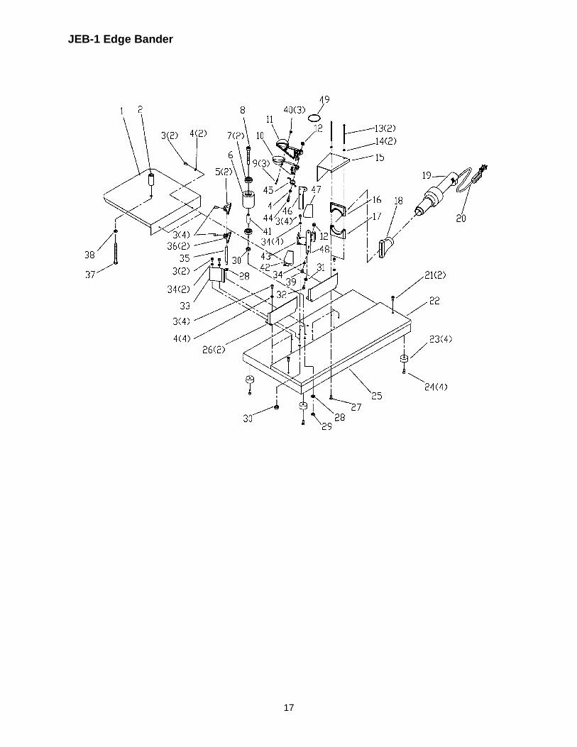
Parts List: JEB-1 Edge Bander
Index No. Part No. Description Size Qty 1...............JEB-101.................. Support Table.................................................... ...................................1 2...............JEB-102.................. Stud................................................................... ...................................1 3...............TS-1503021 ............ Socket Head Cap Screw.................................... M6 × 10 .................... 16 4...............JEB-104.................. Flat Washer ....................................................... M6 × 20 ......................7 5...............JEB-105.................. Upper Edge Guide............................................. ...................................2 6...............JEB-106.................. Roller................................................................. ...................................1 7...............BB-6200ZZ.............. Ball Bearing ....................................................... #6200ZZ.....................2 8...............TS-1505131 ............ Socket Head Cap Screw.................................... M10 × 80 ....................1 9...............TS-1533052 ............ Phillips Pan Head Machine Screw...................... M5 × 16 ......................3 10.............JEB-110.................. Handle (Right) ................................................... ...................................1 11.............JEB-111.................. Handle (Left)...................................................... ...................................1 12.............TS-1541021 ............ Nylon Lock Hex Nut ........................................... M6..............................2 13.............JEB-113.................. Retaining Clamp Screw...................................... M5 × 60 ......................2 14.............TS-1550031 ............ Flat Washer ....................................................... M5..............................2 15.............JEB-115.................. Heat Shield........................................................ ...................................1 16.............JEB-116.................. Top Retaining Clamp ......................................... ...................................1 17.............JEB-117.................. Bottom Retaining Clamp .................................... ...................................1 18.............JEB-118.................. Nozzle ............................................................... 070236 .......................1 19.............JEB-119.................. Hot Air Gun........................................................ ...................................1 20.............JEB-120.................. Electric Cord...................................................... ...................................1 21.............TS-1514031 ............ Socket Head Flat Screw..................................... M6 × 20 ......................2 22.............JEB-122.................. Work Table........................................................ ...................................1 23.............JEB-123.................. Rubber Foot ...................................................... ...................................4 24.............TS-1482031 ............ Hex Cap Screw.................................................. M6 × 16 ......................4 25.............JEB-125.................. Base.................................................................. ...................................1 26.............JEB-126.................. Fence ................................................................ ...................................2 27.............TS-1533052 ............ Phillips Pan Head Machine Screw...................... M5 × 16 ......................2 28.............TS-1550061 ............ Flat Washer ....................................................... M8..............................4 29.............TS-1540061 ............ Hex Nut ............................................................. M8..............................2 30.............TS-1540071 ............ Hex Nut ............................................................. M10 ............................2 31.............TS-1550041 ............ Flat Washer ....................................................... M6..............................1 32.............TS-1503031 ............ Socket Head Cap Screw.................................... M6 × 12 ......................1 33.............JEB-133.................. Heat Shield........................................................ ...................................1 34.............TS-1550041 ............ Flat Washer ....................................................... M6..............................7 35.............JEB-135.................. Stud................................................................... ...................................2 36.............JEB-136.................. Lower Edge Guide............................................. ...................................2 37.............JEB-137.................. Hex Cap Screw (Full Thread)............................. M8 × 100 ....................1 38.............TS-1540061 ............ Hex Nut ............................................................. M8..............................1 39.............TS-1503041 ............ Socket Head Cap Screw.................................... M6 × 16 ......................1 40.............TS-1540031 ............ Hex Nut ............................................................. M5..............................3 41.............JEB-141.................. Spacer............................................................... ...................................1 42.............JEB-142.................. Knife Guard (Right)............................................ ...................................1 43.............JEB-143.................. Knife Base ......................................................... ...................................1 44.............TS-1503081 ............ Socket Head Cap Screw.................................... M6 × 35 ......................1 45.............JEB-145.................. Spring................................................................ ...................................1 46.............JEB-146.................. Upper Knife ....................................................... ...................................1 47.............JEB-147.................. Knife Guard (Left) .............................................. ...................................1 48.............JEB-148.................. Bottom Knife...................................................... ...................................1 49.............JEB-149.................. Clamp Ring........................................................ ...................................1 50.............JEB-150.................. Double Edge Trimmer (not shown)..................... ...................................1 51.............JEB-151.................. Knives for Double Edge Trimmer, set of 4 (not shown) ...........................1
17
JEB-1 Edge Bander

18
NOTES

19
NOTES

20
WMH Tool Group 2420 Vantage Drive Elgin, Illinois 60123
Phone: 800-274-6848 www.wmhtoolgroup.com