operating instructions and parts manual 15-inch planer
TRANSCRIPT

1
Operating Instructions and Parts Manual 15-inch Planer Models JWP-15B, JWP-15BHH
JET 427 New Sanford Road LaVergne, Tennessee 37086 Part No. M-722150 Ph.: 800-274-6848 Edition 1 01/2019 www.jettools.com Copyright © 2019 JET
JWP-15BHH
JWP-15B
2
1.0 IMPORTANT SAFETY INSTRUCTIONS
WARNING – To reduce risk of injury:
1. Read and understand the entire owner's manual before attempting assembly or operation.
2. Read and understand the warnings posted on the machine and in this manual. Failure to comply with all of these warnings may cause serious injury.
3. Replace the warning labels if they become obscured or removed.
4. This planer is designed and intended for use by properly trained and experienced personnel only. If you are not familiar with the proper and safe operation of a planer, do not use until proper training and knowledge have been obtained.
5. Do not use this planer for other than its intended use. If used for other purposes, JET disclaims any real or implied warranty and holds itself harmless from any injury that may result from that use.
6. Always wear approved safety glasses/face shields while using this machine. Everyday eyeglasses only have impact resistant lenses; they are not safety glasses.
7. Before operating this planer, remove tie, rings, watches and other jewelry, and roll sleeves up past the elbows. Do not wear loose clothing. Confine long hair. Non-slip footwear or anti-skid floor strips are recommended. Do not wear gloves.
8. Kickback occurs when the workpiece is thrown towards the operator at a high rate of speed. If you do not have a clear understanding of kickback and how it occurs, DO NOT operate this machine!
9. Wear ear protectors (plugs or muffs) during extended periods of operation.
10. Make certain the switch is in the OFF position before connecting the machine to the power supply.
11. Make certain the machine is properly grounded.
12. Make all machine adjustments or maintenance with the machine unplugged from the power source.
13. Remove adjusting keys and wrenches. Form a habit of checking to see that keys and adjusting wrenches are removed from the machine before turning it on.
14. Keep safety guards in place at all times when the machine is in use. If removed for maintenance purposes, use extreme caution and replace the guards immediately after completion of maintenance.
15. Check damaged parts. Before further use of the machine, a guard or other part that is damaged should be carefully checked to determine that it will operate properly and perform its intended function. Check for alignment of moving parts, binding of moving parts, breakage of parts, mounting and any other conditions that may affect its operation. A guard or other part that is damaged should be properly repaired or replaced.
16. Provide for adequate space surrounding work area and non-glare, overhead lighting.
17. Keep the floor around the machine clean and free of scrap material, oil and grease.
18. Keep visitors a safe distance from the work area. Keep children away.
19. Make your workshop child proof with padlocks, master switches or by removing starter keys.
20. Give your work undivided attention. Looking around, carrying on a conversation and “horse-play” are careless acts that can result in serious injury.
21. Maintain a balanced stance at all times so that you do not fall into the blade or other moving parts. Do not overreach or use excessive force to perform any machine operation.
22. Use the right tool at the correct speed and feed rate. Do not force a tool or attachment to do a job for which it was not designed. The right tool will do the job better and more safely.
23. Use recommended accessories; improper accessories may be hazardous.
24. Maintain tools with care. Keep blades sharp and clean for the best and safest performance. Follow instructions for lubricating and changing accessories.
25. Turn off the machine before cleaning. Use a brush or compressed air to remove chips or debris — do not use your hands.
26. Do not stand on the machine. Serious injury could occur if the machine tips over.
27. Never leave the machine running unattended. Turn the power off and do not leave the machine until it comes to a complete stop.

3
28. Remove loose items and unnecessary work pieces from the area before starting the machine.
29. Pay particular attention to instructions on reducing risk of kickback.
30. Don’t use in dangerous environment. Don’t use power tools in damp or wet location, or expose them to rain. Keep work area well lighted.
31. To avoid kickbacks, use this machine for single board surfacing only. Never make cuts deeper than 1/8 inch (3mm).
32. Be sure cutterhead rotates under power in a counterclockwise direction when viewed from the motor/drive belt side.
Familiarize yourself with the following safety notices used in this manual:
This means that if precautions are not heeded, it may result in minor injury and/or possible machine damage.
This means that if precautions are not heeded, it may result in serious, or possibly even fatal, injury.
WARNING: This product can expose you to chemicals including titanium dioxide which is known to the State of California to cause cancer, and lead which is known to the State of California to cause cancer and birth defects or other reproductive harm. For more information go to http://www.p65warnings.ca.gov.
WARNING: Drilling, sawing, sanding or machining wood products generates wood dust and other substances known to the State of California to cause cancer. Avoid inhaling dust generated from wood products or use a dust mask or other safeguards for personal protection.
Wood products emit chemicals known to the State of California to cause birth defects or other reproductive harm. For more information go to http://www.p65warnings.ca.gov/wood.

4
2.0 Table of contents Section Page 1.0 IMPORTANT SAFETY INSTRUCTIONS ....................................................................................................... 2 2.0 Table of contents ............................................................................................................................................ 4 3.0 About this manual .......................................................................................................................................... 5 4.0 Specifications ................................................................................................................................................. 6 5.0 Setup and assembly ....................................................................................................................................... 8
5.1 Shipping contents ....................................................................................................................................... 8 5.2 Tools required for assembly ....................................................................................................................... 8 5.3 Location and cleaning ................................................................................................................................ 8 5.4 Handwheel ................................................................................................................................................. 9 5.5 Dust Port .................................................................................................................................................... 9 5.6 Extension tables ......................................................................................................................................... 9 5.7 Levelers .................................................................................................................................................... 10
6.0 Electrical connections .................................................................................................................................. 10 6.1 GROUNDING INSTRUCTIONS ............................................................................................................... 10 6.2 Extension cords ........................................................................................................................................ 10
7.0 Adjustments ................................................................................................................................................. 11 7.1 Belt tension/replacement .......................................................................................................................... 11 7.2 Replacing knives (JWP-15B only) ............................................................................................................ 11 7.3 Replacing/rotating knife inserts (JWP-15BHH only) ................................................................................. 12
8.0 Operation ..................................................................................................................................................... 12 8.1 Start switch ............................................................................................................................................... 12 8.2 Depth of Cut ............................................................................................................................................. 13 8.3 Feed speed .............................................................................................................................................. 13 8.4 Transmission rollers overview .................................................................................................................. 13 8.5 Anti-kickback fingers ................................................................................................................................ 13 8.6 Feed rollers spring tension ....................................................................................................................... 13 8.7 Feed rollers height .................................................................................................................................... 13 8.8 Chip deflector ........................................................................................................................................... 15 8.9 Feed speed control ................................................................................................................................... 15
9.0 Maintenance ................................................................................................................................................. 15 9.1 General maintenance ............................................................................................................................... 15 9.2 Lubrication ................................................................................................................................................ 15 9.2 Belt replacement ...................................................................................................................................... 16 9.3 Work table parallel to cutterhead .............................................................................................................. 16 9.4 Lubrication points ..................................................................................................................................... 17
10.0 Troubleshooting JWP-15B,15BHH ............................................................................................................. 18 10.1 Performance problems ........................................................................................................................... 18 10.2 Mechanical and electrical problems ....................................................................................................... 19
11.0 Replacement Parts ..................................................................................................................................... 20 11.1.1 Head Assembly – Exploded View ....................................................................................................... 21 11.1.2 Head Assembly – Parts List ................................................................................................................ 22 11.2.1 Column Assembly – Exploded View .................................................................................................... 23 11.2.2 Column Assembly – Parts List ............................................................................................................ 24 11.3.1 Cutterhead Assembly – Exploded View .............................................................................................. 25 11.3.2 Cutterhead Assembly – Parts List ....................................................................................................... 25 11.4.1 Gear Box Assembly – Exploded View ................................................................................................. 26 11.4.2 Gear Box Assembly – Parts List .......................................................................................................... 27 11.5.1 Cabinet Assembly – Exploded View .................................................................................................... 28 11.5.2 Cabinet Assembly – Parts List ............................................................................................................ 29 11.6.1 Extension Table – Exploded View ....................................................................................................... 30 11.6.2 Extension Table, Sheet Metal – Parts List .......................................................................................... 30 11.6.3 Extension Table, Cast Iron – Parts List ............................................................................................... 30 11.7.1 Switch Assembly – Exploded View ..................................................................................................... 31 11.7.2 Switch Assembly – Parts List .............................................................................................................. 31
12.0 Electrical Connections for JWP-15B,15BHH .............................................................................................. 32 13.0 Warranty and service ................................................................................................................................. 33

5
3.0 About this manual This manual is provided by JET, covering the safe operation and maintenance procedures for a JET Model JWP-15B and JWP-15BHH Planer. This manual contains instructions on installation, safety precautions, general operating procedures, maintenance instructions and parts breakdown. Your machine has been designed and constructed to provide consistent, long-term operation if used in accordance with the instructions set forth in this document.
If there are questions or comments, please contact your local supplier or JET. JET can also be reached at our web site: www.jettools.com.
Retain this manual for future reference. If the machine transfers ownership, the manual should accompany it.
Read and understand the entire contents of this manual before attempting assembly or operation. Failure to comply may cause serious injury.
Register your product using the mail-in card or register online -
http://www.jettools.com/us/en/service-and-support/warranty/registration/

6
4.0 Specifications Table 1
Stock number 722150 722155
Model number JWP-15B JWP-15BHH
Motor and Electricals
Motor type Totally enclosed, fan-cooled, induction, capacitor start
Horsepower 3 HP (2.2 kW)
Phase Single
Voltage 230 V only
Cycle 60 Hz
Listed FLA (full load amps) 11 A
Start capacitor 300MFD 125VAC
Run capacitor 60F 250VAC
Motor speed 3450 RPM
On/off switch Magnetic with LED illuminator, 14A overload protector
Power transfer belt to cutterhead; gearbox/chain to feed rollers
Power cord 14AWG x 3C, 7 ft.
Power plug installed CSA/UL 6-15P
Recommended circuit size 1 15 A
Sound emission without load 2 98 dB at 20 in. (508mm) from
infeed table 83 dB at 20 in. (508mm) from
infeed table
Capacities
Maximum cutting width 15 in. (381 mm)
Maximum cutting thickness 6 in. (153 mm)
Maximum cutting depth 3/16 in. (4.7 mm)
Maximum full width depth of cut 1/8 in. (3.1 mm)
Minimum workpiece length 21-1/2 in. (540 mm)
Head movement per one revolution of handwheel 4 mm
Feed rate 16 and 20 FPM
Gearbox oil capacity 420 mL
Cutterhead and feed rollers
Number of cutterhead rows 3 4
Knife type Straight 4-sided knife inserts
Number of knives 3 48
Cutterhead speed 5200 RPM
Cutterhead diameter 2.6 in. (68 mm)
Main materials
Main table Cast iron
Extension tables Steel Cast iron
Cabinet Steel
Infeed roller Aluminum extrusion
Outfeed roller Rubber
Anti-kickback fingers Steel
Dust collection
Dust port diameter 4 in. (102 mm)
Recommended minimum dust collector capacity 600 CFM
Dimensions
Overall dimensions, assembled LxWxH 25.5 x 46.5 x 48 in. (648 x 1181 x 1219 mm)
Table size LxW 15 x 21.45 in. (381 x 545mm) without in/out feed table
15 x 46.5 in. (381 x 1180mm) with in/out feed table
15 x 21.45 in. (381 x 545mm) without in/out feed table
15 x 49.2 in. (381 x 1250mm) with in/out feed table
7
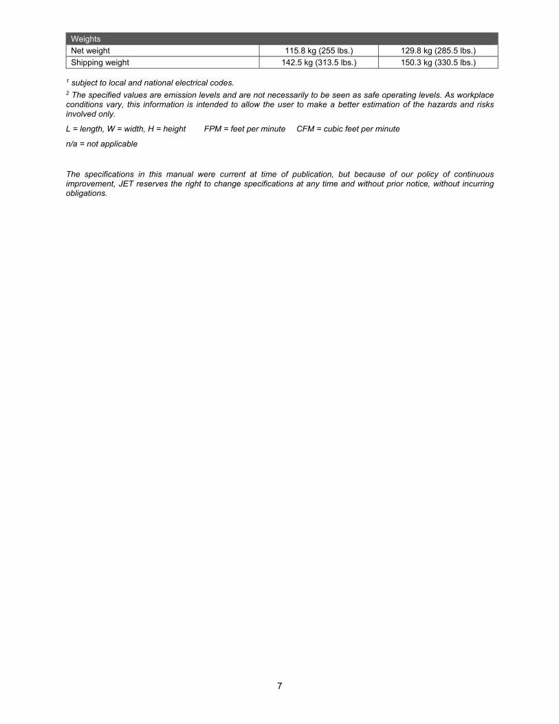
Weights
Net weight 115.8 kg (255 lbs.) 129.8 kg (285.5 lbs.)
Shipping weight 142.5 kg (313.5 lbs.) 150.3 kg (330.5 lbs.)
1 subject to local and national electrical codes. 2 The specified values are emission levels and are not necessarily to be seen as safe operating levels. As workplace conditions vary, this information is intended to allow the user to make a better estimation of the hazards and risks involved only.
L = length, W = width, H = height FPM = feet per minute CFM = cubic feet per minute
n/a = not applicable
The specifications in this manual were current at time of publication, but because of our policy of continuous improvement, JET reserves the right to change specifications at any time and without prior notice, without incurring obligations.

8
Read and understand all setup and assembly instructions before attempting to assemble the machine. Failure to comply may cause serious injury.
IMPORTANT: If you purchased the helical head planer, before operating the machine verify that each knife insert has been properly torqued. Refer to sect. 7.3 for information.
5.0 Setup and assembly Remove all contents from shipping carton. Do not discard packing material until saw is assembled and running satisfactorily.
Inspect contents for shipping damage or part shortages. If either is discovered, report it immediately to your distributor. NOTE: Check machine first in case parts have been pre-installed.
5.1 Shipping contents
See Figures 5-1 and 5-2.
Included with models 15B and 15BHH: 1 Planer (not shown) 1 Handwheel assembly – A 1 Dust port – B 1 Torx point screwdriver T30 (with magnets) – C 1 Operating Instructions and Parts Manual (not
shown) 1 Product registration card (not shown) Included with model 15B only: 2 Steel extension tables (not shown) 1 Hex wrench 6mm – D 1 Knife gauge – E 1 Hardware package (p/n JWP15B-HP) 1 Socket hd cap screw M5x12 – HP1 1 Lock washer M5 – HP2 11 Socket hd button screws M6x12 – HP3 8 Socket hd cap screws M8x16 – HP4 Included with model 15BHH only: 2 Cast iron extension tables (not shown) 2 Star point screwdrivers – F 5 Knife inserts – G 10 Knife insert screws (not shown) 1 Hardware package (p/n JWP15BHH-HP) 1 Socket hd cap screw M5x12 – HP1 1 Lock washer M5 – HP2 11 Socket hd button screws M6x12 – HP3 6 Hex cap screws M8x25 – HP5 6 Set screws M8x20 – HP6
Figure 5-1: contents (not to scale)
Figure 5-2: hardware packages
5.2 Tools required for assembly
4mm hex wrench 6mm hex wrench (for JWP-15B only) Torx point screwdriver T30 (for JWP-15B only) 13mm open-end wrench (for JWP-15BHH only) 16mm open-end wrench Straight edge Level
5.3 Location and cleaning
Use a pallet jack to move the planer close to its final location. Remove any retaining hardware securing planer to pallet, and carefully slide planer off pallet and onto floor.
Use an assistant to slide planer off pallet.

9
The planer should be operated in a well-lit area with good ventilation.
Exposed metal surfaces, such as tables, rollers, cutterhead, etc., may have been given a protective coating at the factory. This can be removed with a soft cloth moistened with a good commercial solvent. Do not use acetone, gasoline, lacquer thinner, or other solvents with a low flash point. Do not use an abrasive pad because it may scratch metal surfaces.
Use care when cleaning around cutterhead area; knives are extremely sharp.
5.4 Handwheel
Install handwheel (A) onto shaft, making sure to orient it with the flat on the shaft. Insert socket hd cap screw with lock washer (HP1,HP2) and tighten. See Figure 5-3.
Figure 5-3: handwheel and dust port
5.5 Dust Port
Mount dust port (B) to rear of head casting with six button head screws (HP3). See Figure 5-3.
It is strongly recommended that you use a dust collection system (not provided) with this planer. Connect a 4-inch dust hose to the port and secure with a hose clamp. Visit JET’s website or contact your dealer for a complete line of dust collectors.
IMPORTANT: If you are not using a dust collection system, do not attach the dust port to the planer, as the accumulation of dust inside the port may create a safety hazard, or eventually cause jamming of the rollers.
5.6 Extension tables
The JWP-15B is shipped with steel tables. The JWP-15BHH is shipped with cast iron tables.
JWP-15B only:
1. Mount the steel extensions to the main table using the screws provided (HP4, Figure 8-9). The bottom screw is used as a stop. The extension table pivots on the top screw.
2. The extension tables must be leveled with the main table. A straight steel bar is ideal for this, but a carefully jointed board may also be used.
Place the straight edge across extension table and main table, as shown in Figure 5-4. Move the straight edge to different places along the table width during the alignment process.
3. Loosen screws (H) with provided Torx point screwdriver and adjust table up or down at each of the four corners as needed until straight edge sits flush across both tables at all points. Tighten screws (H).
Figure 5-4: extension tables (JWP-15B only)
JWP-15BHH only:
1. Insert 3 set screws (HP6, Figure 5-5) into the lower holes of a cast iron extension table.
2. Mount the extension table with three hex cap screws (HP5) using a 13mm wrench. Do not fully tighten yet.
3. Place a straight edge (straight steel bar or carefully jointed board) across extension table and main table, as shown in Figure 5-4.
4. Adjust extension table until it is even with main table, and snug the screws (HP5) a little more. Then turn any of the 3 set screws in or out as needed until straight edge sits flush with extension table and main table at various points along their width.
5. Tighten hex cap screws (HP5).
6. Repeat for opposite extension table.
Figure 5-5: extension tables (JWP-15BHH only)
10
5.7 Levelers
Check the planer for level by placing a bubble level on main table. If adjustment is needed, rotate any of the four leveling pads beneath the cabinet corners. Tighten the hex nuts up against the cabinet to secure the setting.
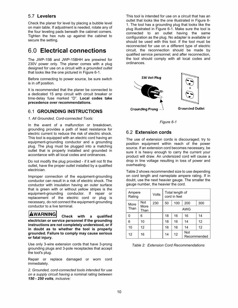
6.0 Electrical connections The JWP-15B and JWP-15BHH are prewired for 230V power only. The planer comes with a plug designed for use on a circuit with a grounded outlet that looks like the one pictured in Figure 6-1.
Before connecting to power source, be sure switch is in off position.
It is recommended that the planer be connected to a dedicated 15 amp circuit with circuit breaker or time-delay fuse marked “D”. Local codes take precedence over recommendations.
6.1 GROUNDING INSTRUCTIONS
1. All Grounded, Cord-connected Tools:
In the event of a malfunction or breakdown, grounding provides a path of least resistance for electric current to reduce the risk of electric shock. This tool is equipped with an electric cord having an equipment-grounding conductor and a grounding plug. The plug must be plugged into a matching outlet that is properly installed and grounded in accordance with all local codes and ordinances.
Do not modify the plug provided - if it will not fit the outlet, have the proper outlet installed by a qualified electrician.
Improper connection of the equipment-grounding conductor can result in a risk of electric shock. The conductor with insulation having an outer surface that is green with or without yellow stripes is the equipment-grounding conductor. If repair or replacement of the electric cord or plug is necessary, do not connect the equipment-grounding conductor to a live terminal.
Check with a qualified electrician or service personnel if the grounding instructions are not completely understood, or if in doubt as to whether the tool is properly grounded. Failure to comply may cause serious or fatal injury.
Use only 3-wire extension cords that have 3-prong grounding plugs and 3-pole receptacles that accept the tool's plug.
Repair or replace damaged or worn cord immediately.
2. Grounded, cord-connected tools intended for use on a supply circuit having a nominal rating between 150 - 250 volts, inclusive:
This tool is intended for use on a circuit that has an outlet that looks like the one illustrated in Figure 6-1. The tool has a grounding plug that looks like the plug illustrated in Figure 6-1. Make sure the tool is connected to an outlet having the same configuration as the plug. No adapter is available or should be used with this tool. If the tool must be reconnected for use on a different type of electric circuit, the reconnection should be made by qualified service personnel; and after reconnection, the tool should comply with all local codes and ordinances.
Figure 6-1
6.2 Extension cords
The use of extension cords is discouraged; try to position equipment within reach of the power source. If an extension cord becomes necessary, be sure it is heavy enough to carry the current your product will draw. An undersized cord will cause a drop in line voltage resulting in loss of power and overheating.
Table 2 shows recommended size to use depending on cord length and nameplate ampere rating. If in doubt, use the next heavier gauge. The smaller the gauge number, the heavier the cord.
Ampere Rating
Volts Total length of cord in feet
More Than
Not More Than
230 50 100 200 300
AWG
0 6 18 16 16 14
6 10 18 16 14 12
10 12 16 16 14 12
12 16 14 12 Not Recommended
Table 2: Extension Cord Recommendations

11
7.0 Adjustments
7.1 Belt tension/replacement
Inspect belt tension frequently during the first few hours of operation, as new belts may stretch during this period. If the belt requires tightening, proceed as follows:
1. Disconnect planer from power source.
2. Remove side panel and belt guard. See Figure 7-1.
3. Loosen four socket hd cap screws (A, Figure 7-1) with 6mm hex wrench, and lower motor slightly until belt is tensioned.
4. Proper tension is achieved when there is about 1/2-inch deflection in the belt midway between the pulleys, using moderate finger pressure.
5. Tighten screws (A), and reinstall belt guard and side panel.
Figure 7-1
7.2 Replacing knives (JWP-15B only)
Use caution and proceed slowly when working with and around the knives – they are extremely sharp.
When dull knives are replaced, care must be exercised in setting the new knives into the cutterhead. The following procedure will ensure a proper setting of knives on the JWP-15B Planer.
1. Disconnect machine from power source.
2. Remove dust hood and top cover.
3. Insert the provided Torx driver (C, Figure 5-1) into hole through belt guard (B, Figure 7-2). Use this to rotate the cutterhead during the procedure.
CAUTION: Always remove hex wrench before starting planer.
4. Loosen the five gib screws (C, Figure 7-2) with a 12mm wrench.
5. Use the magnetic inserts in the Torx drive handle to lift the knife out of the slot. Clean the slot of any dust or pitch.
6. Place the new knife into the cutterhead slot.
7. Place knife gauge onto cutterhead. The knife should just contact the gauge and the gauge sit flush on the cutterhead, as shown in Figure 7-3. If adjustment is needed, turn screws (D, Figure 7-2) in or out with a 3mm hex wrench, until the knife contacts the gauge. Verify this positioning at several points along the knife.
Figure 7-2
Figure 7-3
8. Snug the gib screws to secure the knife; do not fully tighten yet.
9. Rotate cutterhead and repeat process for each of the remaining two knives.
10. Now fully tighten all gib screws on one knife. Do this in sequential order, beginning at one end of the knife and working your way across to the other end, tightening each screw in turn.

12
11. Tighten all gib screws on the other two knives in the same fashion, until all gib screws on the cutterhead are firmly tightened.
(NOTE: The purpose of this incremental tightening process is to prevent any slight deflection or warpage of the cutterhead, and to ensure that each knife is completely seated into the slot.)
After installing knives, check again carefully. Make certain all gib screws are tightened securely. Loose knives can be propelled at high speed from a rotating cutterhead, causing injury.
12. Re-install top cover and dust hood.
7.3 Replacing/rotating knife inserts (JWP-15BHH only)
The knife inserts on the JWP-15BHH are four-sided. When dull, simply remove each insert, rotate it 90° for a fresh edge, and re-install it.
Use a provided star-point driver (F, Figure 5-1) to remove the knife insert screw.
Figure 7-4
It is advisable to rotate all inserts at the same time to maintain consistent cutting. However, if one or more knife inserts develops a nick, rotate only those inserts that are affected.
Each knife insert has an etched reference mark so you can keep track of the rotations.
IMPORTANT: When removing or rotating inserts, clean saw dust from the screw, the insert, and the cutterhead platform. Dust accumulation between these elements can prevent the insert from seating properly, and may affect the quality of the cut.
To install new knife inserts:
1. Disconnect machine from power source.
2. Remove dust hood and top cover.
3. Insert provided Torx driver into hole through belt guard (see B, Figure 7-2). Use this to rotate the cutterhead during the procedure.
CAUTION: Always remove hex wrench before starting planer.
4. Before installing each screw, lightly coat the screw threads with machine oil and wipe off any excess.
5. Position knife insert and move it back and forth to verify there are no burrs or dirt.
6. Hold insert away from the back of the seat (pull slightly toward yourself if facing the cutting edge) and allow the screw to pull insert into position. Note: A slight offset between screw hole and hole in knife insert is normal. Do not position insert directly over screw hole, as it could ride up on the back of the seat and potentially cause cracking of the tip.
7. Securely tighten each knife insert screw before operating the planer.
IMPORTANT: Maximum torque for tightening the screws is 45 to 55 inch pounds (3.75 to 4.6 foot pounds).
Make sure all knife insert screws are tightened securely. Loose inserts can be propelled at high speed from a rotating cutterhead, causing injury.
8.0 Operation
8.1 Start switch
See Figure 8-1.
Press green switch to start planer. Press red switch to stop.
To prevent unauthorized or accidental starting of the planer, remove safety key from switch and store in a safe place. Key must be reinserted to start planer.
Figure 8-1
The planer is equipped with overload protection. If an excess of current is detected, the machine will shut off to prevent damage to motor. If this occurs, wait a few minutes for the machine to cool down, then press the reset button behind the stop paddle.

13
If the planer shuts off frequently, refer to sect. 10.0 Troubleshooting.
8.2 Depth of Cut
The cutting depth scale is a combination inch/metric scale (Figure 8-2), with a cutting range from 0 to 6" (152.4mm). A manual scale is mounted directly to the front column.
The distance of upward or downward movement is controlled by the handwheel.
Figure 8-2
Maximum depth of cut is 3/16". A lip on the front of the head casting (B, Figure 8-2) limits the depth of cut on full width planing under 1/8".
8.3 Feed speed
The gear box has two feed speeds. These are set by pulling out or pushing in the shift lever, located beneath the gearbox cover. Always change feed speed while the machine is running. A diagram showing lever positions is molded into the gearbox cover just above the lever. It is also shown in Figure 8-3.
Planer must be running when changing feed rate. Do not attempt to change feed speed while stock is passing through the machine. Failure to comply may damage gearbox.
Figure 8-3
8.4 Transmission rollers overview
See Figure 8-4.
A. Anti-kickback fingers B. Infeed roller C. Chipbreaker D. Cutterhead E. Outfeed roller
Figure 8-4
8.5 Anti-kickback fingers
The anti-kickback fingers (A, Figure 8-4) are an important safety feature, as they help prevent kickback of stock. They operate by gravity and should be inspected frequently to make sure they are free of gum and pitch, so that they move independently and operate correctly.
8.6 Feed rollers spring tension
The infeed roller (B, Figure 8-4) and outfeed roller (E, Figure 8-4) feed the stock while it is being planed. These rollers are under spring tension and this tension must be sufficient to feed the stock uniformly through the planer without slipping, but should not be so tight that it causes damage to the workpiece. The tension should be equal at both ends of each roller. Note: Contact JET Technical Service before attempting any adjustments to spring tension.
8.7 Feed rollers height
The infeed roller, chipbreaker and outfeed roller are adjusted at the factory. The height relationship between these items and the cutterhead is crucial for accurate and safe planing. The infeed roller and outfeed roller should each be set at 0.032" (0.81mm) below the arc of the cutting knives. The chipbreaker is set even with the cutting arc. See Figure 8-6.
If any adjustments are necessary for the infeed or outfeed roller, they should be done carefully. Use the steps in sect. 8.7.1 as an example of procedure.

14
NOTE: This procedure uses a home-made gauge block and feeler gauges, which should be sufficient for most planer operations. If more precise measurements are desired, use a dial indicator device.
A home-made gauge block can be made out of hardwood. Figure 8-5 is an example.
Figure 8-5
Figure 8-6
8.7.1 Outfeed roller height
1. Disconnect machine from power source.
2. Remove top cover.
3. Make sure knives/knife inserts are properly set.
4. Place gauge block (F, Figure 8-7) on table directly beneath cutterhead (D).
5. Using a 0.032" (0.81mm) feeler gauge (G, Figure 8-7) placed on top of the gauge block, lower head until knife just contacts feeler gauge when knife is at its lowest point. Do not move head any farther until outfeed roller is adjusted.
6. Remove the feeler gauge and move the gauge block under one end of the outfeed roller, as shown in Figure 8-8. The bottom of the outfeed roller should just touch the top of the gauge block. If an adjustment to the outfeed roller is necessary, loosen the lock nut (J) and turn screw (H) until outfeed roller just contacts the gauge block. Then tighten lock nut (J).
7. Check and adjust opposite end of outfeed roller in the same manner.
Figure 8-7
Figure 8-8

15
8.7.2 Infeed roller height
Use the identical procedure for checking the infeed roller as you did for the outfeed roller. Use the 0.032" (0.81mm) feeler gauge atop the gauge block. If adjustment is necessary, use the lock nut and screw on each end of infeed roller.
8.7.3 Chipbreaker height
The chipbreaker breaks off the larger chips before the stock reaches the cutterhead. A spring allows it to adjust automatically for contact with workpiece. No further adjustments should be needed.
8.8 Chip deflector
The chip deflector (Figure 8-9) keeps wood chips from falling into the outfeed roller. The deflector should be set approximately 1/16" to 1/8” from the tip of the knives. Make sure deflector is oriented so that bevel on its front edge matches the shape of the cutterhead.
Figure 8-9
8.9 Feed speed control
Your machine is equipped with a straight, serrated infeed roller and a rubber outfeed roller. When the feed rollers are engaged, they turn to feed the stock. The feed rollers slow automatically when the machine is under heavy load for best planing in all conditions. The feed rollers are driven by chains and sprockets (see Figure 9-1) which take power directly from the cutterhead through the oil bath gear box. The drive chain does not need tensioning, as a spring-loaded tension device (Figure 9-1) maintains proper tension at all times.
To access chain and sprockets, use provided star-point wrench to remove two screws and remove chain guard.
Always re-install cover over chain and sprockets before operating planer.
9.0 Maintenance
Disconnect machine from power source before performing maintenance.
9.1 General maintenance
Periodic or regular inspections are required to ensure that the machine is in proper adjustment, that all screws are tight, that belt is in good condition, that dust has not accumulated in the electrical enclosures, and that there are no worn or loose electrical connections.
Buildup of sawdust and other debris can cause your machine to plane inaccurately. Periodic cleaning is not only recommended but mandatory for accurate planing.
Close-fitting parts, such as the cutterhead slot and gibs, should be cleaned with a cloth or brush and non-flammable solvent, and freed from clinging foreign matter.
Remove resin and other accumulations from feed rollers and table with a soft rag or stiff brush.
Periodically check the chains for proper tension and adjust accordingly if required.
The table should be kept clean and free of rust. Some users prefer a paste wax on exposed steel and cast iron surfaces. The wax provides a layer of protection as well as reducing friction between lumber and the table, making cuts faster and smoother. Avoid any wax that contains silicone or other synthetic ingredients; these materials can find their way into lumber and make staining and finishing difficult.
Alternatively, aerosol protectants are available from most hardware and tool stores.
9.2 Lubrication
Refer to Table 3 for lubrication points.
The bearings on the cutterhead are factory lubricated and sealed for life; no lubrication is required.
9.2.1 Gearbox
The lubricant in the gear box should be replaced every 2,500 hours. Multi-purpose gear box lubricant will be suitable.
To replace lubricant:
1. Disconnect planer from power source.
2. Remove gear box cover.
3. Remove drain plug (A, Figure 9-1), and remove filler cap (B). Drain the used oil thoroughly. Follow local codes for proper disposal of used oil.

16
4. Reinstall drain plug (A) and fill gearbox with clean lubricant through hole (B).
5. Install and tighten filler cap (B).
Figure 9-1
9.2 Belt replacement
To replace the belt, remove cabinet panel and belt guard (see Figure 7-1). Rotate the pulleys using the belt, while gradually walking the belt off one pulley until it comes free. Use the reverse process to install the new belt, making sure it is seated completely onto the pulley grooves. Check for proper tension (see sect. 7.1).
9.3 Work table parallel to cutterhead
The work table is set parallel to the cutterhead by the manufacturer and no further adjustment should be necessary. If your machine is planing a taper, first check to see if knives or knife inserts are set properly in the cutterhead. Then check to see if main table is set parallel to cutterhead, using the following method. You will need feeler gauges, and a dial gauge or home-made gauge block made of hardwood. This gauge block can be made by following the dimensions shown in Figure 8-5.
1. Disconnect machine from power source.
2. Place gauge block on main table directly under a knife edge. Make slight contact by gently lowering head.
3. Move gauge block to opposite end of table. Distance from table to knife edge should be the same at both ends.
4. If the gap difference is greater than 0.004” and less than 0.016”, perform the adjustment procedure in sect. 9.3.1. If the gap is greater than 0.016”, use procedure in sect. 9.3.2.
9.3.1 Fine adjustment
For gap difference 0.004 to 0.016 inches.
1. On the side of the table that needs correcting, locate the two socket head cap screws for each column (Figure 9-2). Loosen both screws for each column on the side you wish to adjust.
2. Push down or pull up the head assembly in the desired direction. Hold the assembly in position and retighten the cap screws.
3. Check table-to-cutterhead parallelism again as described in the previous section, then repeat steps 1 through 3 if needed until deviation is less than 0.004”.
Figure 9-2
9.3.2 Major adjustment
For gap difference > 0.016 inches.
1. Remove cabinet panels.
2. Pivot outfeed table out of the way (or remove it if cast iron version).
3. Lower head until there is enough motor clearance to reach under and adjust the sprockets.
4. Remove bolt (P, Figure 9-3) and loosen bolt (R) which will allow enough movement of idler sprocket assembly (S) to release tension on chain.
Figure 9-3
5. Remove chain from the particular sprocket on the corner of the base that you need to adjust.
6. Turn the sprocket by hand to bring that corner into adjustment with the other three corners. NOTE: Turning sprocket clockwise will increase the distance between the working table and the

17
head casting; counterclockwise will decrease the distance. This adjustment is very sensitive and it should not be necessary to turn the sprocket more than one or two teeth.
7. When adjustments are correct, replace chain around corner sprocket, slide idler sprocket (S, Figure 9-3) back to re-tension chain, tighten bolt (R) and insert and tighten bolt (P).
9.4 Lubrication points
Items on this chart are referenced to the surrounding illustrations.
Item Action Suitable Types of Lubricant Reference
Drive chain Monthly General purpose grease Figure 9-1
Gear box Drain and refill every 2,500 hours
Standard gear oil, 70-90 weight Figure 9-1
Lead screw (x4) Once every 3 months General purpose grease #3, Figure 9-4
Column (x4) Clean and lubricate weekly Light coat of SAE-30 oil #4, Figure 9-4
Table chain Every 4 to 6 months Grease, or good quality bicycle chain lubricant
#5, Figure 9-5
Feed roller shafts Every 30 hours Clean and apply SAE-30 oil. #6, Figure 9-4
Anti-kickback fingers, infeed roller, cutterhead
Clean and lubricate as needed.
Light coat of SAE-30 oil. Figure 8-4
Table 3
Figure 9-4
Figure 9-5

18
10.0 Troubleshooting JWP-15B,15BHH
10.1 Performance problems
Table 4
Symptom Possible Cause Correction
Snipe
Inadequate support of long boards. Support long boards with an assistant or extension rollers.
Uneven feed roller pressure front to back.
Adjust feed roller pressure.
Dull knives or knife inserts. 15B: Sharpen or replace knives. 15BHH: Rotate or replace inserts.
Lumber not butted properly. Butt end to end each piece of stock as they pass through.
Fuzzy grain.
Planing wood with high moisture content.
Remove moisture by drying, or use different stock.
Dull knives or knife inserts. 15B: Sharpen or replace knives. 15BHH: Rotate or replace inserts.
Torn grain.
Too heavy a cut. Adjust proper depth of cut.
Knives (or inserts) cutting against the grain.
Cut along the grain where possible.
Dull knives or knife inserts. 15B: Sharpen or replace knives. 15BHH: Rotate or replace inserts.
Rough/raised grain.
Dull knives or knife inserts. 15B: Sharpen or replace knives. 15BHH: Rotate or replace inserts.
Too heavy a cut. Adjust proper depth of cut.
Planing wood with high moisture content.
Remove moisture by drying, or use different stock.
Rounded, glossy surface.
Dull knives or knife inserts. 15B: Sharpen or replace knives. 15BHH: Rotate or replace inserts.
Feed rate too slow. Increase feed rate.
Cutting depth too shallow. Increase cutting depth.
Poor feeding of lumber.
Inadequate feed roller pressure. Adjust feed roller tension. If proper tension cannot be achieved, replace feed rollers.
Planer table rough or dirty. Clean pitch and residue from table, and apply paste wax.
Belt slipping on pulleys. Tighten belt.
Surface of feed roller is clogged. Clean pitch and residue off roller.

19
10.2 Mechanical and electrical problems
Table 5
Symptom Possible Cause Correction *
Uneven depth of cut side to side.
Knife projection from cutterhead is incorrect (15B only).
Adjust knife projection.
Table not parallel to cutterhead. Adjust table/cutterhead parallelism.
Board thickness does not match depth of cut scale.
Depth of cut scale is incorrect. Adjust depth of cut scale.
Chain is jumping.
Inadequate tension. Adjust chain tension.
Sprockets misaligned. Align sprockets.
Sprockets are worn. Replace sprockets.
Machine will not start/restart or repeatedly trips circuit breaker or blows fuses.
No incoming power. Verify power connections to planer.
Overload protection has activated.
When planer overloads on the circuit breaker built into the motor starter, it takes time for the machine to cool down before restart. Allow unit to adequately cool, then press reset button.
Planer frequently trips.
One cause of overloading trips which is not electrical in nature is too heavy a cut. The solution is to take a lighter cut. If too deep a cut is not the problem, check for other electrical items (dust collectors, lights, heaters, etc.) being used on the same circuit. The planer should be wired to a dedicated circuit.
Building circuit breaker trips or fuse blows.
Verify that planer is on a circuit of correct size. If circuit size is correct, there is probably a loose electrical lead. Check amp settting on motor starter.
Loose electrical connections.
Go through all the electrical connections on the planer including motor connections, verifying the tightness of each. Look for any signs of electrical arcing which is a sure indicator of loose connections or circuit overload.

20
Symptom Possible Cause Correction *
Machine will not start/restart or repeatedly trips circuit breaker or blows fuses.
(cont.)
Motor starter failure.
Examine motor starter for burned or failed components. If damage is found, replace motor starter. If motor starter looks okay but is still suspect, you have two options: have a qualified electrician test the motor starter for function, or purchase a new starter and establish if that was the problem on changeout. If you have access to a voltmeter, you can separate a starter failure from a motor failure by first, verifying incoming voltage at 230+/-10% and second, checking the voltage between starter and motor at 230+/-10%. If incoming voltage is incorrect, you have a power supply problem. If voltage between starter and motor is incorrect, you have a starter problem.
If voltage between starter and motor is correct, you have a motor problem.
Motor failure.
If electric motor is suspect, you have two options: Have a qualified electrician test the motor for function or remove the motor and take it to a qualified electric motor repair shop and have it tested.
Miswiring of the unit. Check to confirm all electrical connections are correct and properly tight. Make any needed corrections.
On/off switch failure.
If the on/off switch is suspect, you have two options: Have a qualified electrician test the switch for function, or purchase a new on/off switch and establish if that was the problem on changeout.
* WARNING: Some corrections may require a qualified electrician.
11.0 Replacement Parts Replacement parts are listed on the following pages. To order parts or reach our service department, call 1-800-274-6848 Monday through Friday, 8:00 a.m. to 5:00 p.m. CST. Having the Model Number and Serial Number of your machine available when you call will allow us to serve you quickly and accurately.
Non-proprietary parts, such as fasteners, can be found at local hardware stores, or may be ordered from JET. Some parts are shown for reference only, and may not be available individually.

21
11.1.1 Head Assembly – Exploded View
22
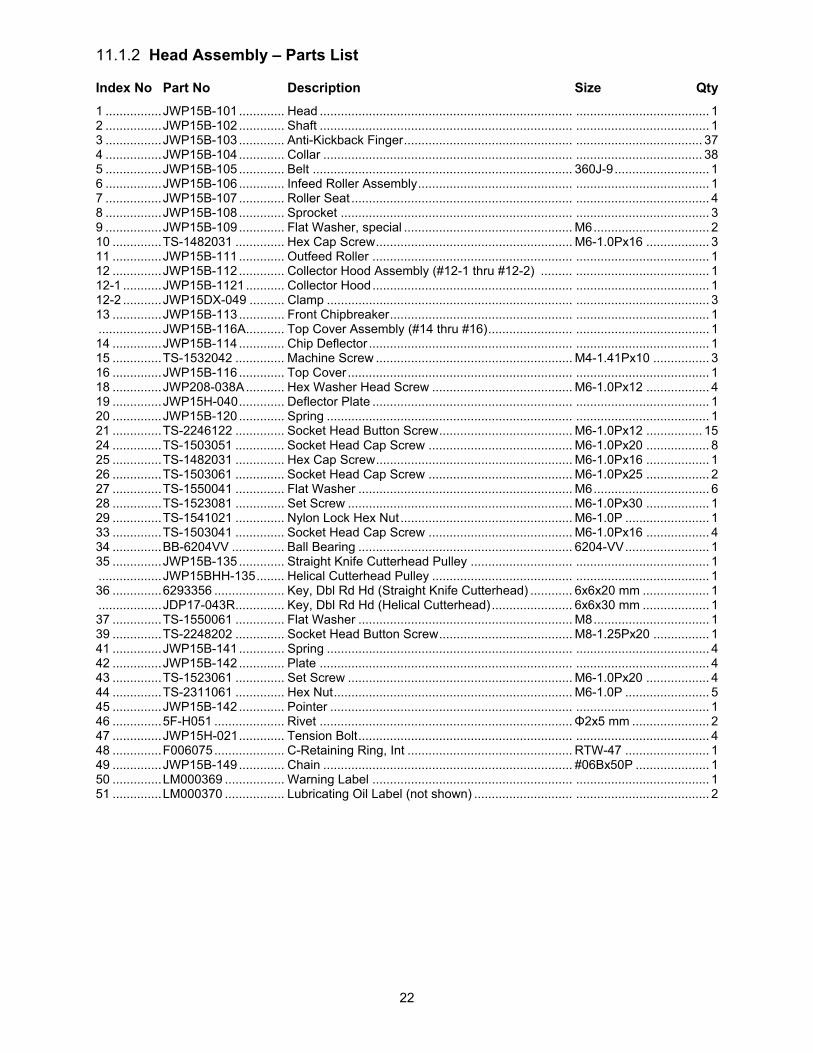
11.1.2 Head Assembly – Parts List
Index No Part No Description Size Qty
1 ................ JWP15B-101 ............. Head ........................................................................ ...................................... 1 2 ................ JWP15B-102 ............. Shaft ........................................................................ ...................................... 1 3 ................ JWP15B-103 ............. Anti-Kickback Finger ................................................ .................................... 37 4 ................ JWP15B-104 ............. Collar ....................................................................... .................................... 38 5 ................ JWP15B-105 ............. Belt .......................................................................... 360J-9 ........................... 1 6 ................ JWP15B-106 ............. Infeed Roller Assembly ............................................ ...................................... 1 7 ................ JWP15B-107 ............. Roller Seat ............................................................... ...................................... 4 8 ................ JWP15B-108 ............. Sprocket .................................................................. ...................................... 3 9 ................ JWP15B-109 ............. Flat Washer, special ................................................ M6 ................................. 2 10 .............. TS-1482031 .............. Hex Cap Screw ........................................................ M6-1.0Px16 .................. 3 11 .............. JWP15B-111 ............. Outfeed Roller ......................................................... ...................................... 1 12 .............. JWP15B-112 ............. Collector Hood Assembly (#12-1 thru #12-2) ......... ...................................... 1 12-1 ........... JWP15B-1121 ........... Collector Hood ......................................................... ...................................... 1 12-2 ........... JWP15DX-049 .......... Clamp ...................................................................... ...................................... 3 13 .............. JWP15B-113 ............. Front Chipbreaker .................................................... ...................................... 1 .................. JWP15B-116A ........... Top Cover Assembly (#14 thru #16) ........................ ...................................... 1 14 .............. JWP15B-114 ............. Chip Deflector .......................................................... ...................................... 1 15 .............. TS-1532042 .............. Machine Screw ........................................................ M4-1.41Px10 ................ 3 16 .............. JWP15B-116 ............. Top Cover ................................................................ ...................................... 1 18 .............. JWP208-038A ........... Hex Washer Head Screw ........................................ M6-1.0Px12 .................. 4 19 .............. JWP15H-040 ............. Deflector Plate ......................................................... ...................................... 1 20 .............. JWP15B-120 ............. Spring ...................................................................... ...................................... 1 21 .............. TS-2246122 .............. Socket Head Button Screw ...................................... M6-1.0Px12 ................ 15 24 .............. TS-1503051 .............. Socket Head Cap Screw ......................................... M6-1.0Px20 .................. 8 25 .............. TS-1482031 .............. Hex Cap Screw ........................................................ M6-1.0Px16 .................. 1 26 .............. TS-1503061 .............. Socket Head Cap Screw ......................................... M6-1.0Px25 .................. 2 27 .............. TS-1550041 .............. Flat Washer ............................................................. M6 ................................. 6 28 .............. TS-1523081 .............. Set Screw ................................................................ M6-1.0Px30 .................. 1 29 .............. TS-1541021 .............. Nylon Lock Hex Nut ................................................. M6-1.0P ........................ 1 33 .............. TS-1503041 .............. Socket Head Cap Screw ......................................... M6-1.0Px16 .................. 4 34 .............. BB-6204VV ............... Ball Bearing ............................................................. 6204-VV ........................ 1 35 .............. JWP15B-135 ............. Straight Knife Cutterhead Pulley ............................. ...................................... 1 .................. JWP15BHH-135 ........ Helical Cutterhead Pulley ........................................ ...................................... 1 36 .............. 6293356 .................... Key, Dbl Rd Hd (Straight Knife Cutterhead) ............ 6x6x20 mm ................... 1 .................. JDP17-043R .............. Key, Dbl Rd Hd (Helical Cutterhead) ....................... 6x6x30 mm ................... 1 37 .............. TS-1550061 .............. Flat Washer ............................................................. M8 ................................. 1 39 .............. TS-2248202 .............. Socket Head Button Screw ...................................... M8-1.25Px20 ................ 1 41 .............. JWP15B-141 ............. Spring ...................................................................... ...................................... 4 42 .............. JWP15B-142 ............. Plate ........................................................................ ...................................... 4 43 .............. TS-1523061 .............. Set Screw ................................................................ M6-1.0Px20 .................. 4 44 .............. TS-2311061 .............. Hex Nut .................................................................... M6-1.0P ........................ 5 45 .............. JWP15B-142 ............. Pointer ..................................................................... ...................................... 1 46 .............. 5F-H051 .................... Rivet ........................................................................ Φ2x5 mm ...................... 2 47 .............. JWP15H-021 ............. Tension Bolt ............................................................. ...................................... 4 48 .............. F006075 .................... C-Retaining Ring, Int ............................................... RTW-47 ........................ 1 49 .............. JWP15B-149 ............. Chain ....................................................................... #06Bx50P ..................... 1 50 .............. LM000369 ................. Warning Label ......................................................... ...................................... 1 51 .............. LM000370 ................. Lubricating Oil Label (not shown) ............................ ...................................... 2
23
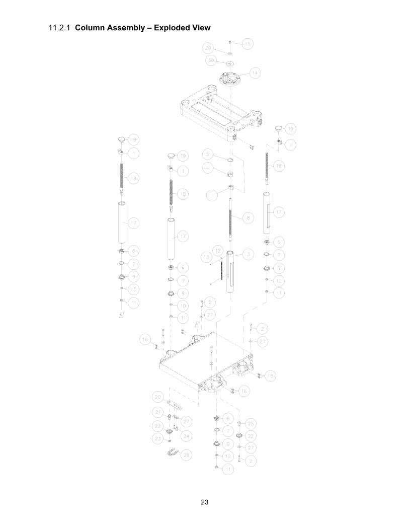
11.2.1 Column Assembly – Exploded View

24
11.2.2 Column Assembly – Parts List
Index No Part No Description Size Qty
1 ................ JWP15H-207 ............. Nut ........................................................................... ...................................... 4 2 ................ TS-1490081 .............. Hex Cap Screw ........................................................ M8-1.25Px45 ................ 5 3 ................ JWP15H-204 ............. Column, Driving ....................................................... ...................................... 1 4 ................ JWP15B-204 ............. Bushing .................................................................... ...................................... 1 5 ................ JWP15H-209 ............. C-Retaining Ring, Int ............................................... RTW-38 ........................ 1 6 ................ BB-6202Z .................. Ball Bearing ............................................................. 6202-Z ......................... 4 7 ................ JWP15H-214 ............. C-Retaining Ring, Int ............................................... RTW-35 ........................ 4 8 ................ JWP15B-208 ............. Lead Screw, Driving ................................................ ...................................... 1 9 ................ JWP15H-216 ............. Sprocket .................................................................. ...................................... 4 10 .............. TS-1550071 .............. Flat Washer ............................................................. M10 ............................... 4 11 .............. TS-1540071 .............. Hex Nut .................................................................... M10-1.25P .................... 4 12 .............. JWP15B-212 ............. Cutting Thickness Scale .......................................... ...................................... 1 13 .............. F001229 .................... Phillips Pan Hd Machine Screw ............................... M3-0.5Px4 .................... 2 14 .............. JPS10TS-SHA .......... Handwheel Assembly .............................................. ...................................... 1 .................. JPS10TS-168 ............ Handwheel (not shown) ........................................... ...................................... 1 .................. JWTS10-146 ............. Handle (not Shown) ................................................. ...................................... 1 .................. JWTS10-145 ............. Handle Cap (not shown) .......................................... ...................................... 1 .................. JWTS10-147 ............. Shaft (not shown) .................................................... ...................................... 1 .................. F011903 .................... Wave Washer (not shown) ...................................... WW-8 ............................ 1 15 .............. TS-1502031 .............. Socket Head Cap Screw ......................................... M5-0.8Px12 .................. 1 16 .............. TS-1525021 .............. Set Screw ................................................................ M10-1.5Px12 ................ 8 17 .............. JWP15H-203 ............. Column, Driven ........................................................ ...................................... 3 18 .............. JWP15H-205 ............. Lead Screw, Driven ................................................. ...................................... 3 19 .............. JWP16OS-129 .......... Cap .......................................................................... ...................................... 3 20 .............. JWP15H-221 ............. Bracket .................................................................... ...................................... 1 21 .............. JWP15H-222 ............. Shaft ........................................................................ ...................................... 1 22 .............. JWP15H-223 ............. Sprocket .................................................................. ...................................... 2 23 .............. JWP15H-224 ............. C-Retaining Ring, Ext .............................................. STW-15 ......................... 1 24 .............. TS-1490041 .............. Hex Cap Screw ........................................................ M8-1.25Px25 ................ 2 25 .............. JWP15B-225 ............. Sleeve ...................................................................... ...................................... 1 27 .............. TS-1550061 .............. Flat Washer ............................................................. M8 ................................. 7 28 .............. JWP16OS-216 .......... Chain ....................................................................... Z410*148P .................... 1 29 .............. TS-2361051 .............. Lock Washer ............................................................ M5 ................................. 1 30 .............. LM000371 ................. Direction Label ......................................................... ...................................... 1
25
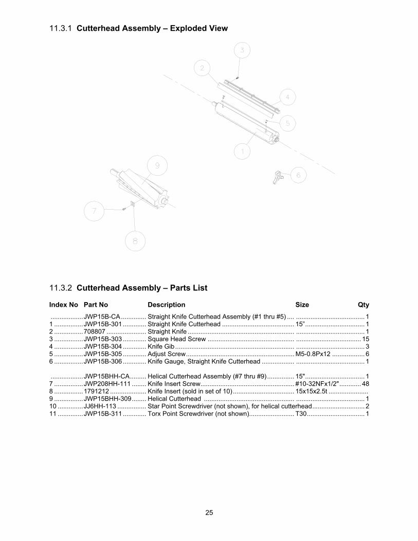
11.3.1 Cutterhead Assembly – Exploded View
11.3.2 Cutterhead Assembly – Parts List
Index No Part No Description Size Qty
.................. JWP15B-CA .............. Straight Knife Cutterhead Assembly (#1 thru #5) .... ...................................... 1 1 ................ JWP15B-301 ............. Straight Knife Cutterhead ........................................ 15” ................................. 1 2 ................ 708807 ...................... Straight Knife ........................................................... ...................................... 1 3 ................ JWP15B-303 ............. Square Head Screw ................................................ .................................... 15 4 ................ JWP15B-304 ............. Knife Gib .................................................................. ...................................... 3 5 ................ JWP15B-305 ............. Adjust Screw ............................................................ M5-0.8Px12 .................. 6 6 ................ JWP15B-306 ............. Knife Gauge, Straight Knife Cutterhead .................. ...................................... 1 .................. JWP15BHH-CA ......... Helical Cutterhead Assembly (#7 thru #9) ............... 15" ................................. 1 7 ................ JWP208HH-111 ........ Knife Insert Screw.................................................... #10-32NFx1/2" ............ 48 8 ................ 1791212 .................... Knife Insert (sold in set of 10) .................................. 15x15x2.5t ...................... 9 ................ JWP15BHH-309 ........ Helical Cutterhead .................................................. ...................................... 1 10 .............. JJ6HH-113 ................ Star Point Screwdriver (not shown), for helical cutterhead ............................. 2 11 .............. JWP15B-311 ............. Torx Point Screwdriver (not shown)......................... T30 ................................ 1

26
11.4.1 Gear Box Assembly – Exploded View

27
11.4.2 Gear Box Assembly – Parts List
Index No Part No Description Size Qty
1 ................ JWP15B-401 ............. Gear Box Cover ....................................................... ...................................... 1 2 ................ TS-2246122 .............. Socket Head Button Screw ...................................... M6-1.0Px12 .................. 2 .................. JWP15B-GBA ........... Gear Box with Straight Cutterhead Assembly (#14 thru #45) ........................... .................. JWP15BHH-GBA ...... Gear Box with Helical Cutterhead Assembly (#14 thru #45) ............................ 4 ................ JWP15B-404 ............. Idler Bracket ............................................................ ...................................... 1 7 ................ TS-1502051 .............. Socket Head Cap Screw ......................................... M5-0.8Px20 .................. 1 8 ................ PA-C61 ...................... Spring ...................................................................... ...................................... 1 9 ................ TS-1540031 .............. Hex Nut .................................................................... M5-0.8P ........................ 1 11 .............. TS-1482031 .............. Hex Cap Screw ........................................................ M6-1.0Px16 .................. 1 12 .............. JWP15B-412 ............. Bolt .......................................................................... ...................................... 1 13 .............. TS-1504051 .............. Socket Head Cap Screw ......................................... M8-1.25Px25 ................ 4 14 .............. BB-6204VV ............... Ball Bearing ............................................................. 6204-VV ........................ 3 15 .............. JWP15B-415 ............. Gear ......................................................................... ...................................... 1 16 .............. JWP15B-416 ............. Gear Box Casting .................................................... ...................................... 1 17 .............. JWP15B-417 ............. Gear Box Cover ....................................................... ...................................... 1 18 .............. JWP15H-336 ............. Gasket ..................................................................... ...................................... 1 19 .............. 6284843 .................... Oil Seal .................................................................... TC28*40*8 .................... 1 20 .............. BB-6201VV ............... Ball Bearing ............................................................. 6201-VV ........................ 5 21 .............. JWP15B-421 ............. Shaft ........................................................................ ...................................... 1 22 .............. JWP15B-422 ............. Gear ......................................................................... 52T ................................ 1 23 .............. 6292768 .................... Key, Dbl Rd Hd ........................................................ 5x5x12 mm ................... 1 24 .............. JWP15H-314 ............. Shaft ........................................................................ ...................................... 1 25 .............. JWP15H-312 ............. Gear ......................................................................... ...................................... 1 26 .............. JWP15H-313 ............. Key .......................................................................... 5x5x10 mm ................... 1 27 .............. JWP15H-323 ............. Shaft ........................................................................ ...................................... 1 28 .............. JWP15H-317 ............. Gear Assembly ........................................................ ...................................... 1 29 .............. JWP15H-320 ............. Key, Dbl Rd Hd ........................................................ 6x6x40 mm ................... 1 30 .............. JWP15H-322 ............. Spring ...................................................................... ...................................... 1 31 .............. SB-6MM .................... Steel Ball ................................................................. Φ 6mm .......................... 1 32 .............. OS-25476 .................. Oil Seal .................................................................... SC25*47*6 .................... 1 33 .............. JWP15H-333 ............. Oil Seal .................................................................... P12 ............................... 1 34 .............. JWP15B-434 ............. Sprocket .................................................................. ...................................... 1 35 .............. JWP15H-335 ............. Pin ........................................................................... ...................................... 2 36 .............. TS-1503061 .............. Socket Head Cap Screw ......................................... M6-1.0Px25 .................. 5 37 .............. JWP15H-339 ............. Oil Plug .................................................................... PT1/4"-19 ...................... 2 38 .............. JWP15H-329 ............. Clutch ...................................................................... ...................................... 1 39 .............. JWP15H-330 ............. Handle ..................................................................... ...................................... 1 40 .............. JWP15H-334 ............. Knob ........................................................................ ...................................... 1 42 .............. JWP15B-109 ............. Flat Washer ............................................................. M6 ................................. 2 43 .............. TS-1503031 .............. Socket Head Cap Screw ......................................... M6-1.0PX12 .................. 1 44 .............. JWP208-038A ........... Hex Bolt ................................................................... M6-1.0Px12 .................. 1 45 .............. JWP15B-CA .............. Straight Knife Cutterhead Assembly ........................ ...................................... 1 .................. JWP15BHH-CA ......... Helical Cutterhead Assembly................................... 15" ................................. 1 46 .............. JWP15B-446 ............. Chain ....................................................................... #06B*41P ...................... 1

28
11.5.1 Cabinet Assembly – Exploded View

29
11.5.2 Cabinet Assembly – Parts List
Index No Part No Description Size Qty
1 ................ TS-1550041 .............. Flat Washer ............................................................. M6 ................................. 4 2 ................ TS-2246122 .............. Socket Head Button Screw ...................................... M6-1.0Px12 .................. 2 3 ................ JWP15B-503 ............. Belt Cover ................................................................ ...................................... 1 4 ................ JWP15B-504 ............. Motor Plate .............................................................. ...................................... 1 5 ................ TS-1503051 .............. Socket Head Cap Screw ......................................... M6-1.0Px20 .................. 4 6 ................ TS-2361061 .............. Lock Washer ............................................................ M6 ................................. 8 7 ................ TS-1504041 .............. Socket Head Cap Screw ......................................... M8-1.25Px20 ................ 5 8 ................ TS-2361081 .............. Lock Washer ............................................................ M8 ................................. 5 9 ................ TS-1504051 .............. Socket Head Cap Screw ......................................... M8-1.25Px25 ................ 2 10 .............. JWP15B-510 ............. Sleeve ...................................................................... ...................................... 3 11 .............. TS-1541031 .............. Nylon Lock Hex Nut ................................................. M8-1.25P ...................... 3 12 .............. TS-1550061 .............. Flat Washer ............................................................. M8 ................................. 7 13 .............. JWP15B-513 ............. Set Screw ................................................................ M8-1.25Px35 ................ 1 14 .............. JWP15B-514 ............. Gas Strut ................................................................. 350N ............................. 1 15 .............. JWP15B-515 ............. Cabinet .................................................................... ...................................... 1 16 .............. JPS10TSC-305 ......... Leveler Pad ............................................................. ..................................... 4 17 .............. TS-1540061 .............. Hex Nut .................................................................... M8-1.25P ...................... 4 18 .............. JWP15B-518 ............. Cable Protector ........................................................ NB-2430 ........................ 1 19 .............. JWP15B-519 ............. Door ......................................................................... ...................................... 2 20 .............. TS-2246122 .............. Socket Head Button Screw ...................................... M6-1.0Px12 ................ 10 21 .............. JWP15B-707 ............. Strain Relief ............................................................. SB7R-3 ......................... 2 22 .............. JWP15B-522 ............. Motor (includes #25) ................................................ 3HP*230V*60HZ ........... 1 .................. JWP15B-SC .............. Start Capacitor ......................................................... 300MFD 125VAC .......... 1 .................. JWP15B-RC .............. Run Capacitor .......................................................... 60F 250VAC ............... 1 23 .............. 5509069 .................... Key, Dbl Rd Hd ........................................................ 6x6x18mm .................... 1 24 .............. JWP15B-524 ............. Motor Pulley ............................................................. ...................................... 1 25 .............. LM000372 ................. Motor Label, JWP-15B............................................. 3HP*230V*60HZ ........... 1 26 .............. TS-1550061 .............. Flat Washer ............................................................. M8 ................................. 2 27 .............. TS-1490031 .............. Hex Cap Screw ........................................................ M8-1.25Px20 ................ 1 28 .............. JWP15B-528 ............. Plastic Washer ......................................................... ...................................... 2 30 .............. JWP15B-713 ............. Plate ........................................................................ ...................................... 1 32 .............. JET-92 ....................... JET Logo ................................................................. 92x38mm ...................... 1 33 .............. 15S-278 ..................... Belt Cover Warning Label (not shown) .................... ...................................... 1 34 .............. JWP15B-534 ............. Adjustable Bracket ................................................... ...................................... 2 35 .............. TS-1503041 .............. Socket Head Cap Screw ......................................... M6-1.0Px16 .................. 4 36 .............. JWP15B-536 ............. Gas Strut ................................................................. 200N ............................. 1 37 .............. LM000373 ................. ID label, Straight CH ................................................ ...................................... 1 .................. LM000374 ................. ID label, Helical CH ................................................. ...................................... 1

30
11.6.1 Extension Table – Exploded View
11.6.2 Extension Table, Sheet Metal – Parts List
Index No Part No Description Size Qty
.................. JWP15B-SETA .......... Steel Extension Table Assembly (#1 thru #3) ......... ........................................ 1 ................ JWP15B-601 ............. Steel Extension Table .............................................. ...................................... 2 2 ................ JWP15B-602 ............. Support .................................................................... ...................................... 4 3 ................ JWP15B-603 ............. Torx Head Screw ..................................................... M6-1.0Px12 .................. 8 5 ................ JWP15B-605 ............. Main Table ............................................................... ...................................... 1 6 ................ TS-1504031 .............. Socket Head Cap Screw ......................................... M8-1.25Px16 ................ 8 .................. TS-152707 ................ Allen Wrench (not shown) ....................................... 6mm .............................. 1
11.6.3 Extension Table, Cast Iron – Parts List
Index No Part No Description Size Qty
.................. JWP15BHH-CETA .... Cast Iron Extension Table Assembly (#7 thru #9) ... ........................................ 7 ................ JWP15BHH-607 ........ Cast Iron Extension Table ....................................... ...................................... 2 8 ................ TS-1524051 .............. Set Screw ................................................................ M8-1.25Px20 ................ 6 9 ................ TS-1490041 .............. Hex Cap Screw ........................................................ M8-1.25Px25 ................ 6

31
11.7.1 Switch Assembly – Exploded View
11.7.2 Switch Assembly – Parts List
Index No Part No Description Size Qty
.................. JWP15B-SA .............. Switch Assembly (#1 thru #13) ................................ ...................................... 1 1 ................ JWP15B-701 ............. Control Panel Kit ...................................................... ...................................... 1 .................. JWP15B-SK .............. Safety Key (not shown)............................................ ...................................... 1 2 ................ JWP15B-702 ............. Overload Protector .................................................. 14A ............................... 1 3 ................ JWP15B-703 ............. Machine Screw ........................................................ M4-1.41Px10 .............. 10 4 ................ TS-2284082 .............. Phillips Pan Hd Machine Screw ............................... M4-0.7Px8 .................... 2 5 ................ JWP15B-705 ............. Switch Box ............................................................... ...................................... 1 6 ................ JWP15B-706 ............. Contactor ................................................................. ...................................... 1 7 ................ JWP15B-707 ............. Strain Relief ............................................................. SB7R-3 ......................... 3 8 ................ TS-1532032 .............. Phillips Pan Hd Machine Screw ............................... M4-0.7Px10 .................. 2 9 ................ JWP15B-709 ............. Grounding Plate ....................................................... ...................................... 1 10 .............. F001995 .................... Ext Tooth Lock Washer ........................................... #8 (M4) ......................... 2 11 .............. JWP15B-711 ............. Power Cable ............................................................ 14AWG*3C*3100mm .... 1 12 .............. JWP15B-712 ............. Motor Cable ............................................................. 14AWG*3C*850mm ...... 1 13 .............. JWP15B-713 ............. Plate ........................................................................ ...................................... 1 14 .............. TS-2246122 .............. Socket Head Button Screw ...................................... M6-1.0Px12 .................. 2

32
12.0 Electrical Connections for JWP-15B,15BHH

33
13.0 Warranty and service JET warrants every product it sells against manufacturers’ defects. If one of our tools needs service or repair, please contact Technical Service by calling 1-800-274-6846, 8AM to 5PM CST, Monday through Friday.
Warranty Period The general warranty lasts for the time period specified in the literature included with your product or on the official JET branded website.
JET products carry a limited warranty which varies in duration based upon the product. (See chart below) Accessories carry a limited warranty of one year from the date of receipt. Consumable items are defined as expendable parts or accessories expected to become inoperable within a
reasonable amount of use and are covered by a 90 day limited warranty against manufacturer’s defects.
Who is Covered This warranty covers only the initial purchaser of the product from the date of delivery.
What is Covered This warranty covers any defects in workmanship or materials subject to the limitations stated below. This warranty does not cover failures due directly or indirectly to misuse, abuse, negligence or accidents, normal wear-and-tear, improper repair, alterations or lack of maintenance. JET woodworking machinery is designed to be used with Wood. Use of these machines in the processing of metal, plastics, or other materials outside recommended guidelines may void the warranty. The exceptions are acrylics and other natural items that are made specifically for wood turning.
Warranty Limitations Woodworking products with a Five Year Warranty that are used for commercial or industrial purposes default to a Two Year Warranty. Please contact Technical Service at 1-800-274-6846 for further clarification.
How to Get Technical Support Please contact Technical Service by calling 1-800-274-6846. Please note that you will be asked to provide proof of initial purchase when calling. If a product requires further inspection, the Technical Service representative will explain and assist with any additional action needed. JET has Authorized Service Centers located throughout the United States. For the name of an Authorized Service Center in your area call 1-800-274-6846 or use the Service Center Locator on the JET website.
More Information JET is constantly adding new products. For complete, up-to-date product information, check with your local distributor or visit the JET website.
How State Law Applies This warranty gives you specific legal rights, subject to applicable state law.
Limitations on This Warranty JET LIMITS ALL IMPLIED WARRANTIES TO THE PERIOD OF THE LIMITED WARRANTY FOR EACH PRODUCT. EXCEPT AS STATED HEREIN, ANY IMPLIED WARRANTIES OF MERCHANTABILITY AND FITNESS FOR A PARTICULAR PURPOSE ARE EXCLUDED. SOME STATES DO NOT ALLOW LIMITATIONS ON HOW LONG AN IMPLIED WARRANTY LASTS, SO THE ABOVE LIMITATION MAY NOT APPLY TO YOU. JET SHALL IN NO EVENT BE LIABLE FOR DEATH, INJURIES TO PERSONS OR PROPERTY, OR FOR INCIDENTAL, CONTINGENT, SPECIAL, OR CONSEQUENTIAL DAMAGES ARISING FROM THE USE OF OUR PRODUCTS. SOME STATES DO NOT ALLOW THE EXCLUSION OR LIMITATION OF INCIDENTAL OR CONSEQUENTIAL DAMAGES, SO THE ABOVE LIMITATION OR EXCLUSION MAY NOT APPLY TO YOU. JET sells through distributors only. The specifications listed in JET printed materials and on official JET website are given as general information and are not binding. JET reserves the right to effect at any time, without prior notice, those alterations to parts, fittings, and accessory equipment which they may deem necessary for any reason whatsoever. JET® branded products are not sold in Canada by JPW Industries, Inc.
Product Listing with Warranty Period 90 Days – Parts; Consumable items 1 Year – Motors; Machine Accessories 2 Year – Metalworking Machinery; Electric Hoists, Electric Hoist Accessories; Woodworking Machinery used for industrial or commercial purposes 5 Year – Woodworking Machinery Limited Lifetime – JET Parallel clamps; VOLT Series Electric Hoists; Manual Hoists; Manual Hoist Accessories; Shop Tools; Warehouse & Dock products; Hand Tools; Air Tools
NOTE: JET is a division of JPW Industries, Inc. References in this document to JET also apply to JPW Industries, Inc., or any of its successors in interest to the JET brand.

34
This page intentionally left blank.

35
This page intentionally left blank.

36
427 New Sanford Road LaVergne, Tennessee 37086
Phone: 800-274-6848 www.jettools.com