operating instruction booklet - amazon s3 · operating instruction booklet - translation of the...
TRANSCRIPT
011651en
Operating Instruction Booklet - Translation of the original instructions -
Stationary Screwdriver Spindle MINIMAT
Motor Size 2
347-228-31 386369 A
347-328-31 386369 B
347-528-31 386369 C
NOTICE ALL DOCUMENTATIONS ! Before beginning work this operating instruction booklet and the enclosed safety instructions (no. 016000, pink-colored booklet) have to be read through carefully. Always follow the instructions during operation. Give this operating in-struction booklet and the appropriate safety instructions to the operator.
2
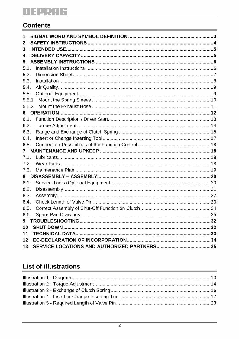
Contents
1 SIGNAL WORD AND SYMBOL DEFINITION .................. .............................................3 2 SAFETY INSTRUCTIONS .............................................................................................4 3 INTENDED USE.............................................................................................................5 4 DELIVERY CAPACITY .................................. ................................................................5 5 ASSEMBLY INSTRUCTIONS .............................. .........................................................6 5.1. Installation Instructions...............................................................................................6 5.2. Dimension Sheet........................................................................................................7 5.3. Installation ..................................................................................................................8 5.4. Air Quality...................................................................................................................9 5.5. Optional Equipment....................................................................................................9 5.5.1 Mount the Spring Sleeve ........................................................................................10 5.5.2 Mount the Exhaust Hose ........................................................................................11 6 OPERATION................................................................................................................12 6.1. Function Description / Driver Start............................................................................13 6.2. Torque Adjustment ...................................................................................................14 6.3. Range and Exchange of Clutch Spring ....................................................................15 6.4. Insert or Change Inserting Tool................................................................................17 6.5. Connection-Possibilities of the Function Control ......................................................18 7 MAINTENANCE AND UPKEEP ............................. .....................................................18 7.1. Lubricants.................................................................................................................18 7.2. Wear Parts ...............................................................................................................18 7.3. Maintenance Plan.....................................................................................................19 8 DISASSEMBLY – ASSEMBLY............................. .......................................................20 8.1. Service Tools (Optional Equipment).........................................................................20 8.2. Disassembly.............................................................................................................21 8.3. Assembly..................................................................................................................22 8.4. Check Length of Valve Pin .......................................................................................23 8.5. Correct Assembly of Shut-Off Function on Clutch....................................................24 8.6. Spare Part Drawings ................................................................................................25 9 TROUBLESHOOTING.................................... .............................................................32 10 SHUT DOWN .............................................................................................................32 11 TECHNICAL DATA..................................... ...............................................................33 12 EC-DECLARATION OF INCORPORATION.................... ..........................................34 13 SERVICE LOCATIONS AND AUTHORIZED PARTNERS.......... ..............................35
List of illustrations
Illustration 1 - Diagram.......................................................................................................13 Illustration 2 - Torque Adjustment ......................................................................................14 Illustration 3 - Exchange of Clutch Spring..........................................................................16 Illustration 4 - Insert or Change Inserting Tool ...................................................................17 Illustration 5 - Required Length of Valve Pin......................................................................23

3
1 Signal Word and Symbol Definition
The signal words and symbols used in the technical documentation (safety instructions, operating instruction booklet, etc.) have the following meaning:
DANGER
Indicates an immediate danger which causes serious injuries or even death if not avoided.
WARNING
Indicates a threatening danger which can cause serious injuries or even death if not avoided.
CAUTION
Indicates a danger or unsafe procedure which can cause injuries to a per-son or material damages if not avoided.
NOTICE
Indicates a potentially dangerous situation which can cause damage to the product or its surroundings if not avoided.
IMPORTANT
Indicates tips and other useful information.
In each case the symbol used does not replace the safety text. The text must always be read fully. In some cases other symbols will be used with the signal words.
4
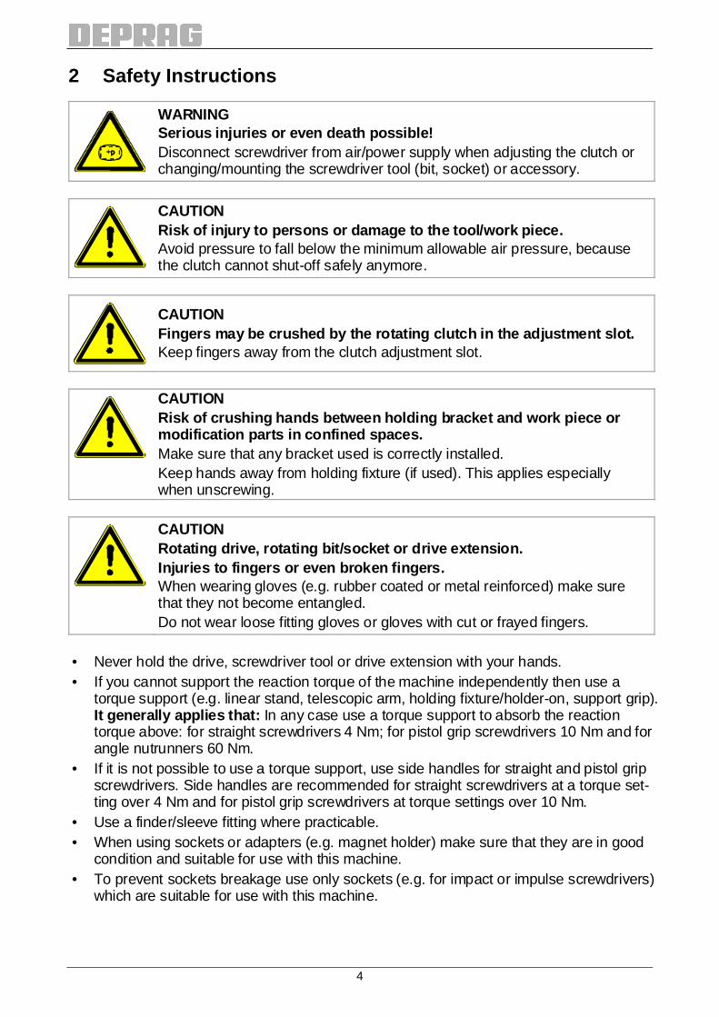
2 Safety Instructions
WARNING Serious injuries or even death possible! Disconnect screwdriver from air/power supply when adjusting the clutch or changing/mounting the screwdriver tool (bit, socket) or accessory.
CAUTION Risk of injury to persons or damage to the tool/wor k piece. Avoid pressure to fall below the minimum allowable air pressure, because the clutch cannot shut-off safely anymore.
CAUTION Fingers may be crushed by the rotating clutch in th e adjustment slot. Keep fingers away from the clutch adjustment slot.
CAUTION Risk of crushing hands between holding bracket and work piece or modification parts in confined spaces. Make sure that any bracket used is correctly installed. Keep hands away from holding fixture (if used). This applies especially when unscrewing.
CAUTION Rotating drive, rotating bit/socket or drive extens ion. Injuries to fingers or even broken fingers. When wearing gloves (e.g. rubber coated or metal reinforced) make sure that they not become entangled. Do not wear loose fitting gloves or gloves with cut or frayed fingers.
• Never hold the drive, screwdriver tool or drive extension with your hands. • If you cannot support the reaction torque of the machine independently then use a
torque support (e.g. linear stand, telescopic arm, holding fixture/holder-on, support grip). It generally applies that: In any case use a torque support to absorb the reaction torque above: for straight screwdrivers 4 Nm; for pistol grip screwdrivers 10 Nm and for angle nutrunners 60 Nm.
• If it is not possible to use a torque support, use side handles for straight and pistol grip screwdrivers. Side handles are recommended for straight screwdrivers at a torque set-ting over 4 Nm and for pistol grip screwdrivers at torque settings over 10 Nm.
• Use a finder/sleeve fitting where practicable. • When using sockets or adapters (e.g. magnet holder) make sure that they are in good
condition and suitable for use with this machine. • To prevent sockets breakage use only sockets (e.g. for impact or impulse screwdrivers)
which are suitable for use with this machine.
5
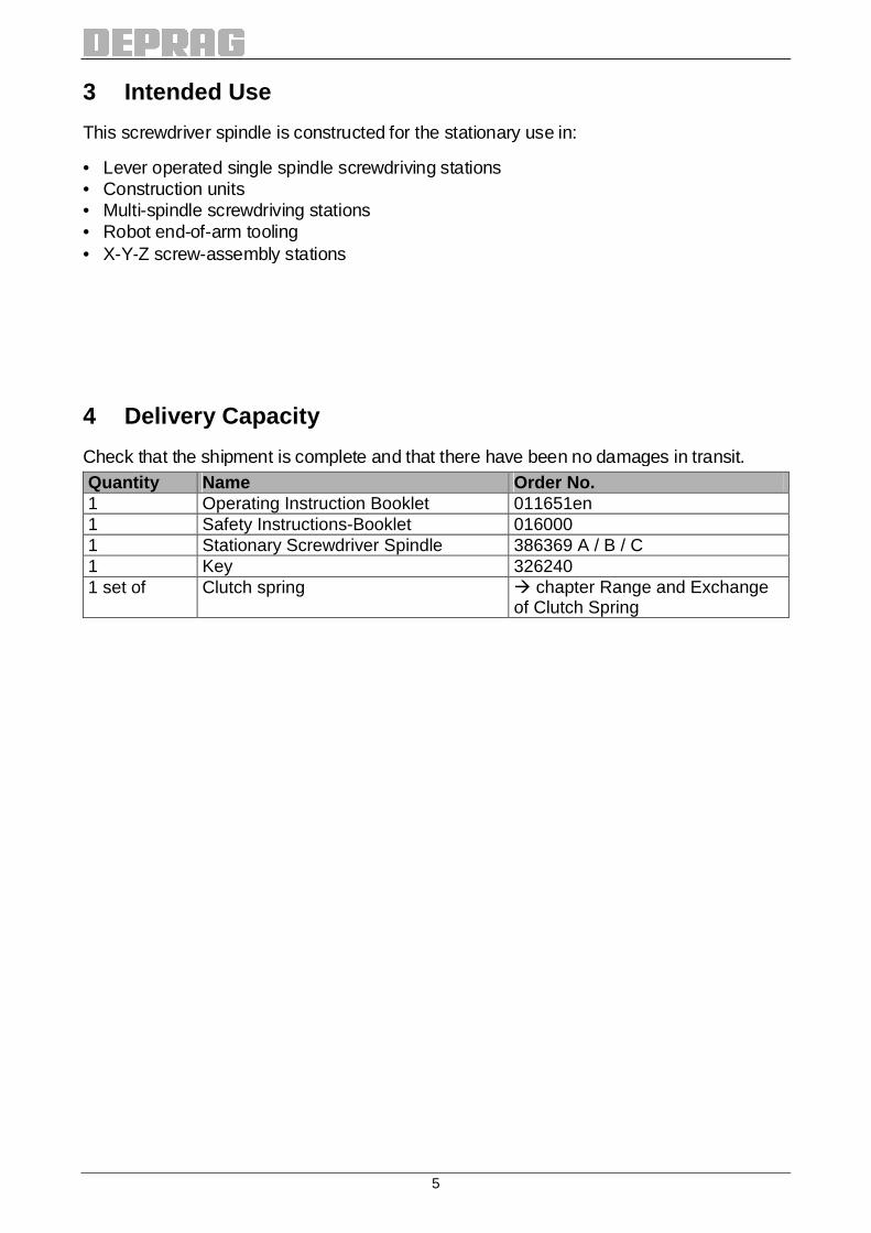
3 Intended Use
This screwdriver spindle is constructed for the stationary use in:
• Lever operated single spindle screwdriving stations • Construction units • Multi-spindle screwdriving stations • Robot end-of-arm tooling • X-Y-Z screw-assembly stations
4 Delivery Capacity
Check that the shipment is complete and that there have been no damages in transit. Quantity Name Order No. 1 Operating Instruction Booklet 011651en 1 Safety Instructions-Booklet 016000 1 Stationary Screwdriver Spindle 386369 A / B / C 1 Key 326240 1 set of Clutch spring � chapter Range and Exchange
of Clutch Spring
6
5 Assembly Instructions
WARNING Air under pressure can cause severe injury. Disconnect tool from air/power supply prior to assembly, installation and maintenance work.
5.1. Installation Instructions When installing the screwdriver spindle the following points have to be observed:
• Install the screwdriver spindle according to the Dimension Sheet. • The screwdriver spindle may be installed in any orientation. • Use only mounting brackets having a sufficient size (� Dimension Sheet). • Use only the mounting elements delivered to mount the screwdriver spindle. • Level the screwdriver spindle and the screwdriving position so that there are no or only
low radial forces (e.g. by dead load).
Support plates are not included in delivery of the screwdriver spindle. Make sure to choose a suitable material (e.g. steel with tensile strength Rm ≥ 370 N/m²) for support plates.
Make sure not to exceed the max. driver stroke (� Dimension Sheet) dur-ing screwdriving.
7
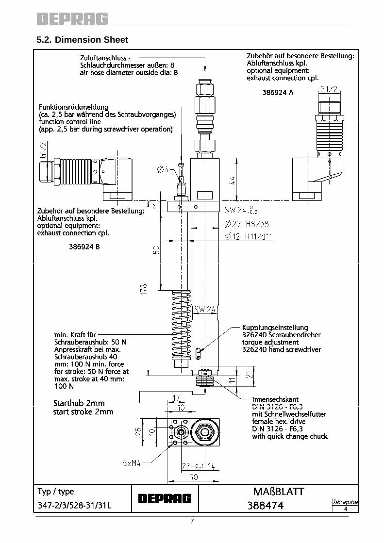
5.2. Dimension Sheet

8
5.3. Installation
• Before connecting the air supply line to the screwdriver, clean the air pipe and the air hose by slightly blowing air into the pipe/hose in order to remove any dirt particles. Wear safety goggles!
• Make sure, that all air lines have a sufficient cross-section (� chapter Technical Data) and that there are no throttle areas, bends or kinks.
• If the air supply line is longer than 2 meters, the next larger hose I.D. should be in-stalled in order to avoid a loss of power.
• This pneumatic screwdriver spindle may be operated either with or without lubricated air. The best performance is achieved by adding 1 – 2 drops of oil per 1 m³ of air con-sumption. When operating with oil-free air, a performance reduction of up to 20% oc-curs and maintenance requirements increases.
• The air supply to the screwdriver has to be filtered. • The maintenance unit, the valves and the silencers have to be selected according to
the air consumption of the screwdriver (� chapter Technical Data). Install components, which have a measurement that will limit the pressure drop – when measured from the maintenance unit to the screwdriver – to less than 0.5 bar (7.25 PSI).
• Use only lubricants approved by the manufacturer. We recommend: special oil „DEPRAGOL“, order no. 790081 E (250 cm³ = 8.45 fl. oz).
• Check flow-pressure at directly on the machine. The pressure regulator needs to be adjusted to an airflow between 5.0 (71 PSI) and 6.3 bar (90 PSI). A higher pressure leads to increased wear and tear. A lower pressure may lead to clutch not being able to correctly shut-off the motor i.e. the preset torque will not be reached.
• Connect the screwdriver spindle as follows: a) For standard operation, connect to a maintenance unit consisting of filter with water
separator, pressure regulator and oiler. Air Consumption Thread Size Order No. 0,05 - 0,5 m³/min G 1/4 820454 A 0,15 – 1,5 m³/min G 1/2 820455 A 0,8 – 6,0 m³/min G 3/4 821608 A
b) For the use with minimal lubrication, connect to a filter-regulator consisting of filter with water separator and pressure regulator, in connection with a point-of-use oiler (order no. 378077 A, 1-fold)
Air Consumption Thread Size Order No. 0,05 - 0,5 m³/min G 1/4 822408 A 0,15 – 0,9 m³/min G 3/8 826981 A 0,15 – 1,5 m³/min G 1/2 822409 A 0,8 – 6,0 m³/min G 3/4 826982 A
c) For oil-free operation, connect to a filter-regulator consisting of filter with water se-parator and pressure regulator.
Air Consumption Thread Size Order No. 0,05 - 0,5 m³/min G 1/4 822408 A 0,15 – 0,9 m³/min G 3/8 826981 A 0,15 – 1,5 m³/min G 1/2 822409 A 0,8 – 6,0 m³/min G 3/4 826982 A
Recommendation: The preferred lubricating method for screwdrivers mounted in fixtures, brackets, machines etc. (in connection with controller) is method b) with point-of-use oiler.

9
5.4. Air Quality With regard to air quality according to ISO 8573-1 we recommend:
Class Residual Oil Residual Dust Residual Water
content
mg/m³
particle size µm
max. concentration
mg/m³
pressure dew-point
°C
max. concentration
g/m³ Lubricated air 4 5 15 8 +3 6 Oil-free air 3 1 5 5 -20 0.88
5.5. Optional Equipment Name Order No. Exhaust connection vertical (with 2 m / 6.6 ft. hose) 386924 A )* Exhaust connection horizontal (with 2 m / 6.6 ft. hose) 386924 B )* Depth control, double on request Spring sleeve cpl. (without induction – in connection with finder) 364672 A Spring sleeve cpl. (with induction – in connection with finder) 364672 C PE-Converter 811341
)* for corresponding exhaust filter/silencer, see catalog D3340 Pressure hoses, connecting components, etc. � catalog D3340 All catalogs are available for download from our web site: www.deprag.com
You will find suitable inserting tools • in our catalog D3320 or • on the internet as follows: www.deprag.com
→ Screwdriving Technology → Selection program: Inserting tools

10
5.5.1 Mount the Spring Sleeve
Operating Screwdriver with a Finder: Installation of the finder (optional equipment):
• Remove screw cap (left-hand thread) from spring sleeve. • Insert finder and pressure spring into spring sleeve. • Re-attach screw cap onto spring sleeve (left-hand thread). • Assemble complete spring sleeve package to screwdriver (left-hand thread).
Finder and bit are not included in the delivery capacity of the spring sleeve. You will find suitable inserting tools • in our catalog D3320 or • on the internet as follows: www.deprag.com
→ Screwdriving Technology → Selection program: Inserting tools
Assembly- and Spare Parts Drawing SPRING SLEEVE CP L. 364672 A
Assembly- and Spare Parts Drawing SPRING SLEEVE CP L. 364672 C
11
5.5.2 Mount the Exhaust Hose
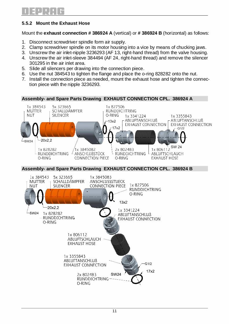
Mount the exhaust connection # 386924 A (vertical) or # 386924 B (horizontal) as follows:
1. Disconnect screwdriver spindle form air supply. 2. Clamp screwdriver spindle on its motor housing into a vice by means of chucking jaws. 3. Unscrew the air inlet-nipple 3236293 (AF 13, right-hand thread) from the valve housing. 4. Unscrew the air inlet-sleeve 384494 (AF 24, right-hand thread) and remove the silencer
301295 in the air inlet area. 5. Slide all silencers per drawing into the connection piece. 6. Use the nut 384543 to tighten the flange and place the o-ring 828282 onto the nut. 7. Install the connection piece as needed, mount the exhaust hose and tighten the connec-
tion piece with the nipple 3236293.
Assembly- and Spare Parts Drawing EXHAUST CONNECTI ON CPL. 386924 A
Assembly- and Spare Parts Drawing EXHAUST CONNECTI ON CPL. 386924 B
12
6 Operation
On delivery, the screwdriver is preset to the maximum or customer-specific torque value. For start-up perform the following steps:
1. If needed, adjust clutch to the required torque value. � chapter Torque Adjustment
The required torque adjustment can be checked using a torque wrench or measuring platform (see DEPRAG catalogs D3020 and D3022). This equipment can also be used to re-adjust the torque of the screwdriver.
2. If necessary, exchange clutch spring. � chapter Range and Exchange of Clutch Spring
IMPORTANT To operate the clutch, using a clutch spring which either surpasses or falls below its specified torque range, leads to a reduction of the torque accuracy.
3. Mount inserting tool, e.g. bit or socket. � chapter Insert or Change Inserting Tool 4. Connect main air hose (hose diameter � chapter Technical Data). The flow pressure
must not drop below 5 bar/71 PSI – reduced output! 5. Connect pneumatic function control line (� chapter Connection-Possibilities of the
Function Control). Required hose I.D. � chapter Technical Data
The noise level can be further reduced, when an exhaust connection with connected Filter/Silencer is used.
13
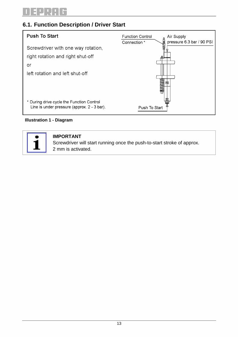
6.1. Function Description / Driver Start
Illustration 1 - Diagram
IMPORTANT Screwdriver will start running once the push-to-start stroke of approx. 2 mm is activated.
14
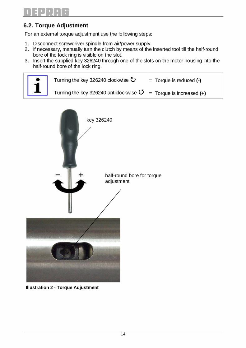
6.2. Torque Adjustment For an external torque adjustment use the following steps:
1. Disconnect screwdriver spindle from air/power supply. 2. If necessary, manually turn the clutch by means of the inserted tool till the half-round
bore of the lock ring is visible on the slot. 3. Insert the supplied key 326240 through one of the slots on the motor housing into the
half-round bore of the lock ring.
Turning the key 326240 clockwise ���� = Torque is reduced (-)
Turning the key 326240 anticlockwise ���� = Torque is increased (+)
Illustration 2 - Torque Adjustment
half-round bore for torque adjustment
key 326240
15
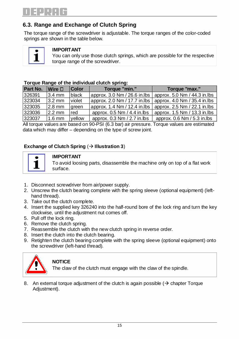
6.3. Range and Exchange of Clutch Spring The torque range of the screwdriver is adjustable. The torque ranges of the color-coded springs are shown in the table below.
IMPORTANT You can only use those clutch springs, which are possible for the respective torque range of the screwdriver.
Torque Range of the individual clutch spring: Part No. Wire ∅∅∅∅ Color Torque "min." Torque "max." 326391 3.4 mm black approx. 3.0 Nm / 26.6 in.lbs approx. 5.0 Nm / 44.3 in.lbs 323034 3.2 mm violet approx. 2.0 Nm / 17.7 in.lbs approx. 4.0 Nm / 35.4 in.lbs 323035 2.8 mm green approx. 1.4 Nm / 12.4 in.lbs approx. 2.5 Nm / 22.1 in.lbs 323036 2.2 mm red approx. 0.5 Nm / 4.4 in.lbs approx. 1.5 Nm / 13.3 in.lbs 323037 1.6 mm yellow approx. 0.3 Nm / 2.7 in.lbs approx. 0.6 Nm / 5.3 in.lbs All torque values are based on 90-PSI (6.3 bar) air pressure. Torque values are estimated data which may differ – depending on the type of screw joint. Exchange of Clutch Spring (� Illustration 3)
IMPORTANT To avoid loosing parts, disassemble the machine only on top of a flat work surface.
1. Disconnect screwdriver from air/power supply. 2. Unscrew the clutch bearing complete with the spring sleeve (optional equipment) (left-
hand thread). 3. Take out the clutch complete. 4. Insert the supplied key 326240 into the half-round bore of the lock ring and turn the key
clockwise, until the adjustment nut comes off. 5. Pull off the lock ring. 6. Remove the clutch spring. 7. Reassemble the clutch with the new clutch spring in reverse order. 8. Insert the clutch into the clutch bearing. 9. Retighten the clutch bearing complete with the spring sleeve (optional equipment) onto
the screwdriver (left-hand thread).
NOTICE The claw of the clutch must engage with the claw of the spindle.
8. An external torque adjustment of the clutch is again possible (� chapter Torque Adjustment).
16
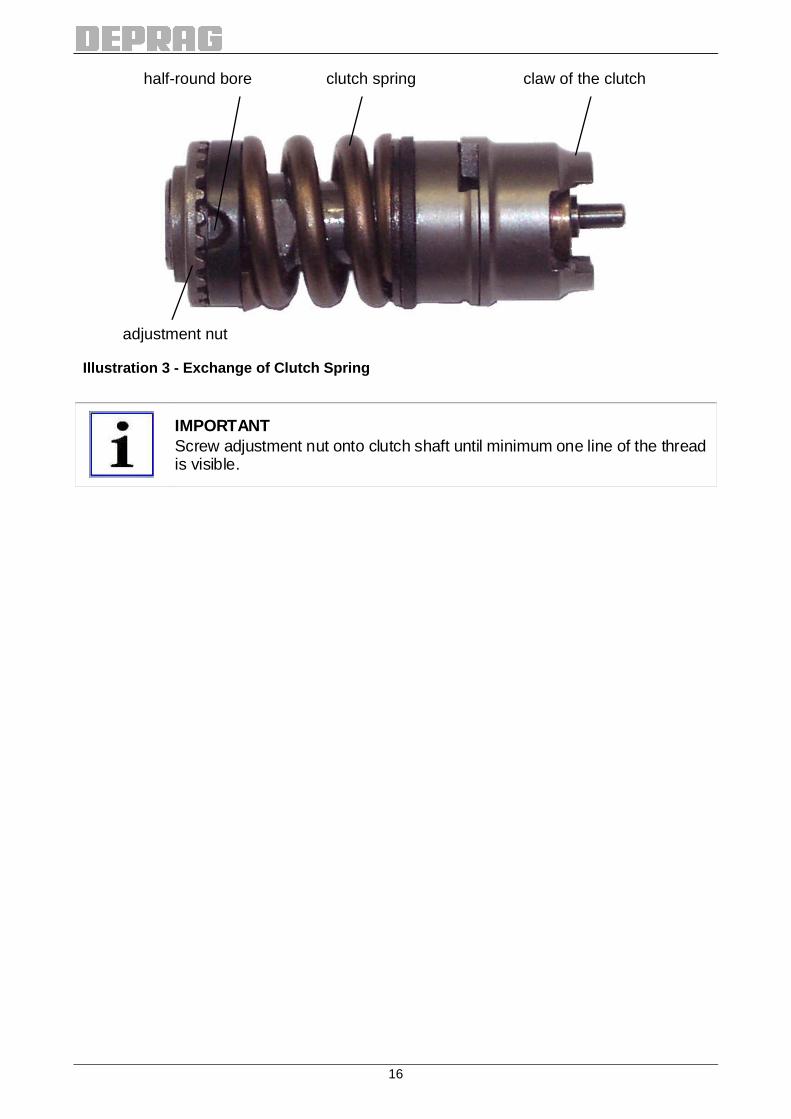
Illustration 3 - Exchange of Clutch Spring
IMPORTANT Screw adjustment nut onto clutch shaft until minimum one line of the thread is visible.
adjustment nut
half-round bore clutch spring claw of the clutch
17
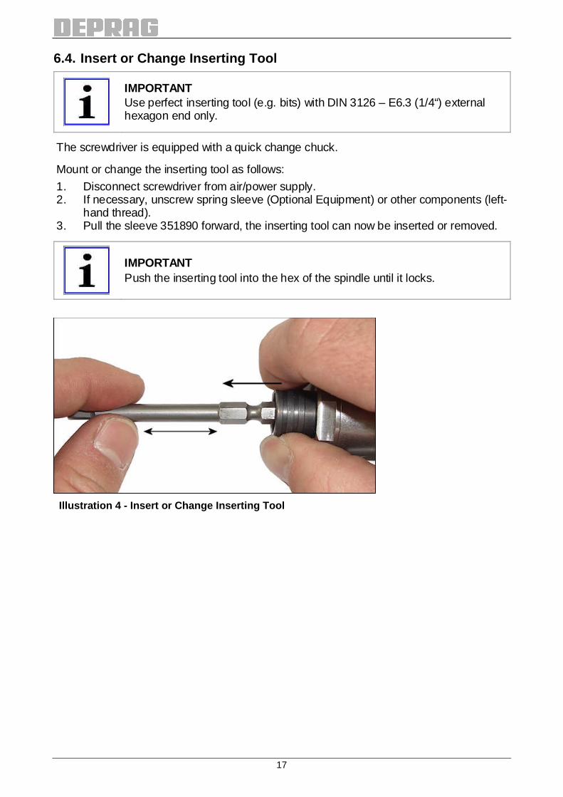
6.4. Insert or Change Inserting Tool
IMPORTANT Use perfect inserting tool (e.g. bits) with DIN 3126 – E6.3 (1/4“) external hexagon end only.
The screwdriver is equipped with a quick change chuck.
Mount or change the inserting tool as follows:
1. Disconnect screwdriver from air/power supply. 2. If necessary, unscrew spring sleeve (Optional Equipment) or other components (left-
hand thread). 3. Pull the sleeve 351890 forward, the inserting tool can now be inserted or removed.
IMPORTANT Push the inserting tool into the hex of the spindle until it locks.
Illustration 4 - Insert or Change Inserting Tool

18
6.5. Connection-Possibilities of the Function Contr ol Use as air pressure outlet during screw -assembly • to control driver start and stop as well as shut-off control of clutch; • as cycle counter of the complete process; each in connection with a PE-Switch or similar.
The function control line is under pressure of appx. 2 – 3 bar during current screw-driving operation only. After reaching the preset torque, the clutch will disengage and turn off the screwdriver. The pressure in the function control line will drop. The screwdriver can now be lifted off the assembled screw/nut.
IMPORTANT If the function control is not needed, the port has to be closed; otherwise there is a loss of power of about 15 %.
7 Maintenance and Upkeep
Incorrect disassembly or assembly can lead to injury of an operator and damage of the ma-chine. Disassembly and assembly work may only be carried out by DEPRAG or qualified personnel.
READ SAFETY INSTRUCTIONS Read and observe the instructions given in the enclosed safety instruction booklet 016000 (see chapter „Maintenance and Upkeep“).
7.1. Lubricants Use only lubricants approved by the manufacturer.
Air supply-lubrication Gearing-lubrication Recommended lubricants for… Name / Order No. Name / Order No.
Standard applications Special oil „DEPRAGOL“ (250 cm³) / 790081 E
DEPRAG-grease (100 g) 807293
7.2. Wear Parts Quantity Part No. Name Belongs to 1 326240 KEY 386369 A / B / C 5 3660053 VANE 386436 A / B 1 802430 O-RING 386359 B 1 802516 O-RING 386369 A / B / C 1 802516 O-RING 382676 A 1 802559 O-RING 382676 A 1 827411 O-RING 386437 A 2 827412 O-RING 389749 A
19
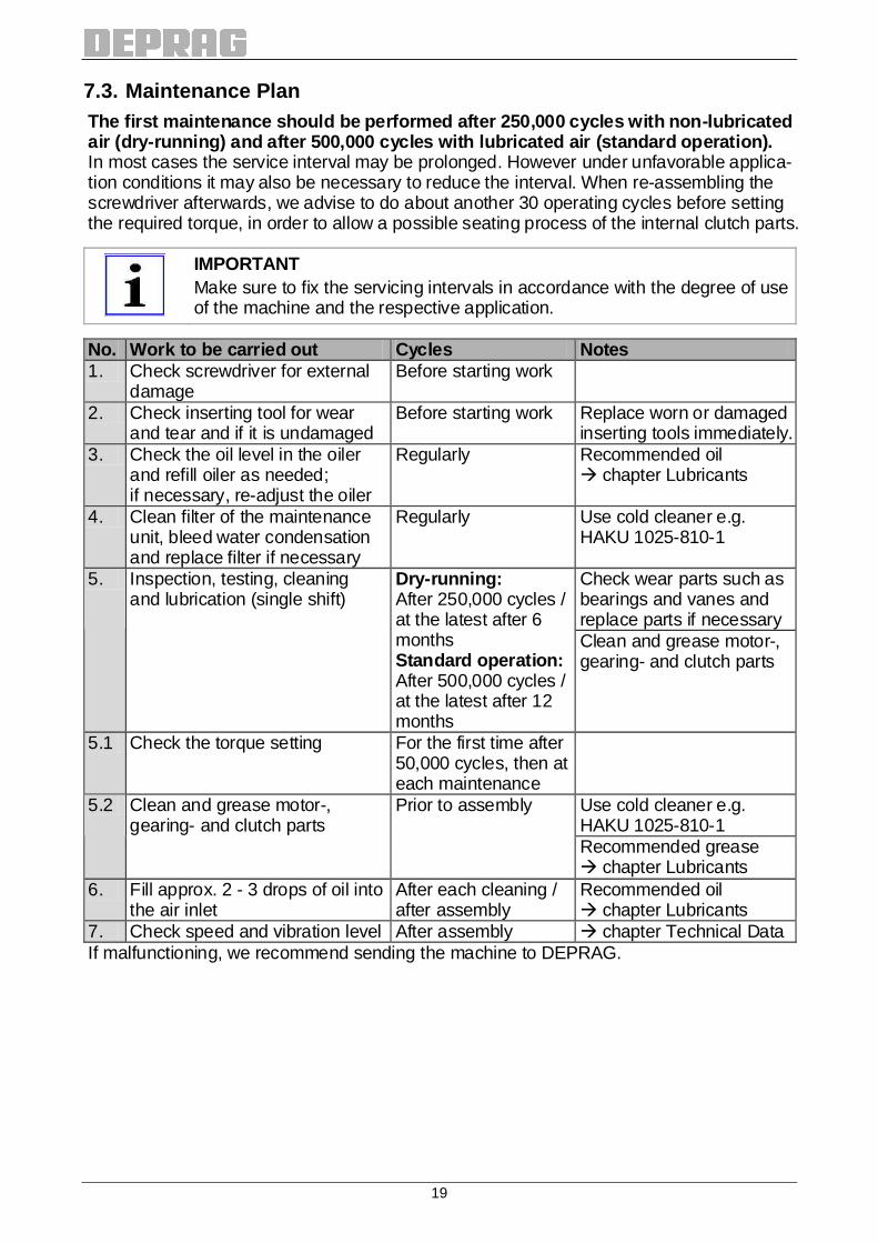
7.3. Maintenance Plan The first maintenance should be performed after 250 ,000 cycles with non -lubricated air (dry-running) and after 500,000 cycles with lub ricated air (standard operation). In most cases the service interval may be prolonged. However under unfavorable applica-tion conditions it may also be necessary to reduce the interval. When re-assembling the screwdriver afterwards, we advise to do about another 30 operating cycles before setting the required torque, in order to allow a possible seating process of the internal clutch parts.
IMPORTANT Make sure to fix the servicing intervals in accordance with the degree of use of the machine and the respective application.
No. Work to be carried out Cycles Notes 1. Check screwdriver for external
damage Before starting work
2. Check inserting tool for wear and tear and if it is undamaged
Before starting work Replace worn or damaged inserting tools immediately.
3. Check the oil level in the oiler and refill oiler as needed; if necessary, re-adjust the oiler
Regularly Recommended oil � chapter Lubricants
4. Clean filter of the maintenance unit, bleed water condensation and replace filter if necessary
Regularly Use cold cleaner e.g. HAKU 1025-810-1
Check wear parts such as bearings and vanes and replace parts if necessary
5. Inspection, testing, cleaning and lubrication (single shift)
Dry-running: After 250,000 cycles / at the latest after 6 months Standard operation: After 500,000 cycles / at the latest after 12 months
Clean and grease motor-, gearing- and clutch parts
5.1 Check the torque setting For the first time after 50,000 cycles, then at each maintenance
Use cold cleaner e.g. HAKU 1025-810-1
5.2 Clean and grease motor-, gearing- and clutch parts
Prior to assembly
Recommended grease � chapter Lubricants
6. Fill approx. 2 - 3 drops of oil into the air inlet
After each cleaning / after assembly
Recommended oil � chapter Lubricants
7. Check speed and vibration level After assembly � chapter Technical Data If malfunctioning, we recommend sending the machine to DEPRAG.

20
8 Disassembly – Assembly
(� Spare Part Drawing/s)
WARNING Machine may start. Severe injuries possible. Disconnect machine from air supply.
CAUTION Incorrect disassembly/assembly can lead to injury o f an operator and damage of the machine. Disassembly and assembly work may only be carried out by DEPRAG or qualified personnel.
NOTICE When disassembling, parts could be lost or damaged. Only disassemble the machine on top of a flat work surface.
NOTICE
Damage to motor housing and internal parts possible. Always use protective chucking jaws when clamping motor housing (into a vice).
8.1. Service Tools (Optional Equipment) Name Order No.. Device (to clamp rotor cylinder; disassembly of Motor) 460474 Arbor (to disassemble bearing cover with grooved rotary joint) 462330 Arbor (to mount circlip 800248 onto spindle 351888) 461292 Chucking jaws (to clamp motor housing 384449) 462048 Pin wrench (for valve housing 384469) 462122 Spanner AF 8 (for slide connector 827785) 800399 Spanner AF 13 (for hex. nut 826715) 800404 Spanner AF 24 (for clutch bearing 386437 A, air inlet-sleeve 384494 and motor housing 384449)
800406

21
8.2. Disassembly 1. Disconnect the screwdriver spindle from air supply. 2. Unscrew the clutch bearing 386437 A complete with the spring sleeve (optional equip-
ment) by means of spanner 800406 (left-hand thread). 3. Take out the clutch 386361 A/B/C complete. 4. Loosen the hex. nut 826715 (AF 13, right-hand thread) on the guide bolt and remove
the guide bolt 389749 A complete. 5. Clamp the screwdriver spindle on its flange 384490 into a vice. 6. Unscrew the air connection 388954 A complete (AF 14, right-hand thread). 7. Unscrew the air inlet-nipple 3236293 (AF 13, right-hand thread) and remove the si-
lencers 301295 and 323665. 8. Unscrew the air inlet-sleeve 384494 (AF 24, right-hand thread). 9. Clamp the screwdriver spindle on its motor housing 384449 into a vice by means of the
chucking jaws 462048 (or hold with spanner AF 24). 10. Pull off the flange 384490. 11. Unscrew the valve housing 384469 by means of the pin wrench 462122 from the motor
housing (right-hand thread). 12. Pull out the valve set 386359 B complete. 13. Push the motor- and gearing parts carefully out of the motor housing by means of a
suitable arbor in direction of the air inlet. 14. Remove the intermediate piece 3844641 and the intermediate plate 3844571 from the
motor package. 15. Pull off the gearing from the motor package. Disassembly of motor : a) Clamp motor on its rotor cylinder into the device (� Service Tools). b) Pull off shaft-side bearing cover from rotor. c) Remove rotor cylinder. d) Take out the vanes and check them thoroughly.
IMPORTANT Too small or damaged vanes have to be replaced in sets .
Basically, use only original vanes from DEPRAG.
e) Pull off air-connecting side bearing cover from rotor. f) Press the two ball bearings from the bearing covers.
IMPORTANT Minimum vanes width should be 5 mm.
22
8.3. Assembly
Lubrication prior to assembly • Fill space areas of the planetary gear with 1/3rd of grease.
(recommended grease � chapter Lubricants) • Sufficiently grease the bearings. • Use only lubricants approved by the manufacturer.
Assembly of motor : a) Clean the rotor. b) Press the ball bearings into the two bearing covers. c) Press the shaft-side bearing cover with the ball bearing onto the rotor. d) Insert the new vanes into the rotor. e) Put the rotor cylinder over the rotor.
IMPORTANT After assembly the bearing covers shouldn’t have any axial gap. The rotor must turn freely.
f) Press the air connecting-side bearing cover with the ball bearing onto the rotor. For assembly proceed logically in reverse order with reference to disassembly.
23
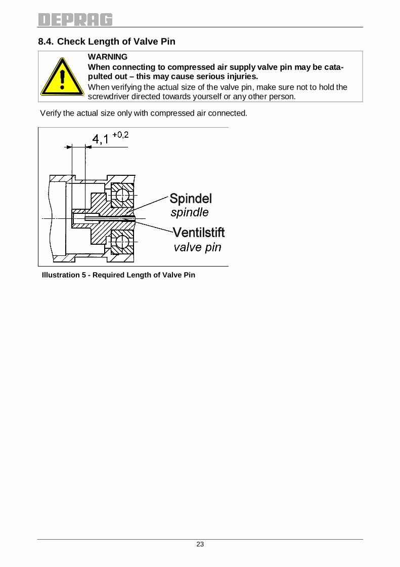
8.4. Check Length of Valve Pin
WARNING When connecting to compressed air supply valve pin may be cata-pulted out – this may cause serious injuries. When verifying the actual size of the valve pin, make sure not to hold the screwdriver directed towards yourself or any other person.
Verify the actual size only with compressed air connected.
Illustration 5 - Required Length of Valve Pin
24
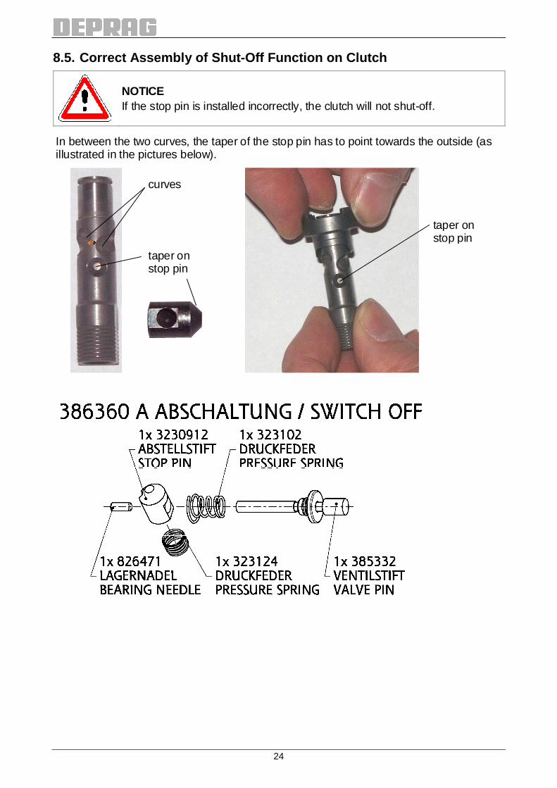
8.5. Correct Assembly of Shut-Off Function on Clutc h
NOTICE If the stop pin is installed incorrectly, the clutch will not shut-off.
In between the two curves, the taper of the stop pin has to point towards the outside (as illustrated in the pictures below).
curves
taper on stop pin
taper on stop pin

25
8.6. Spare Part Drawings

26
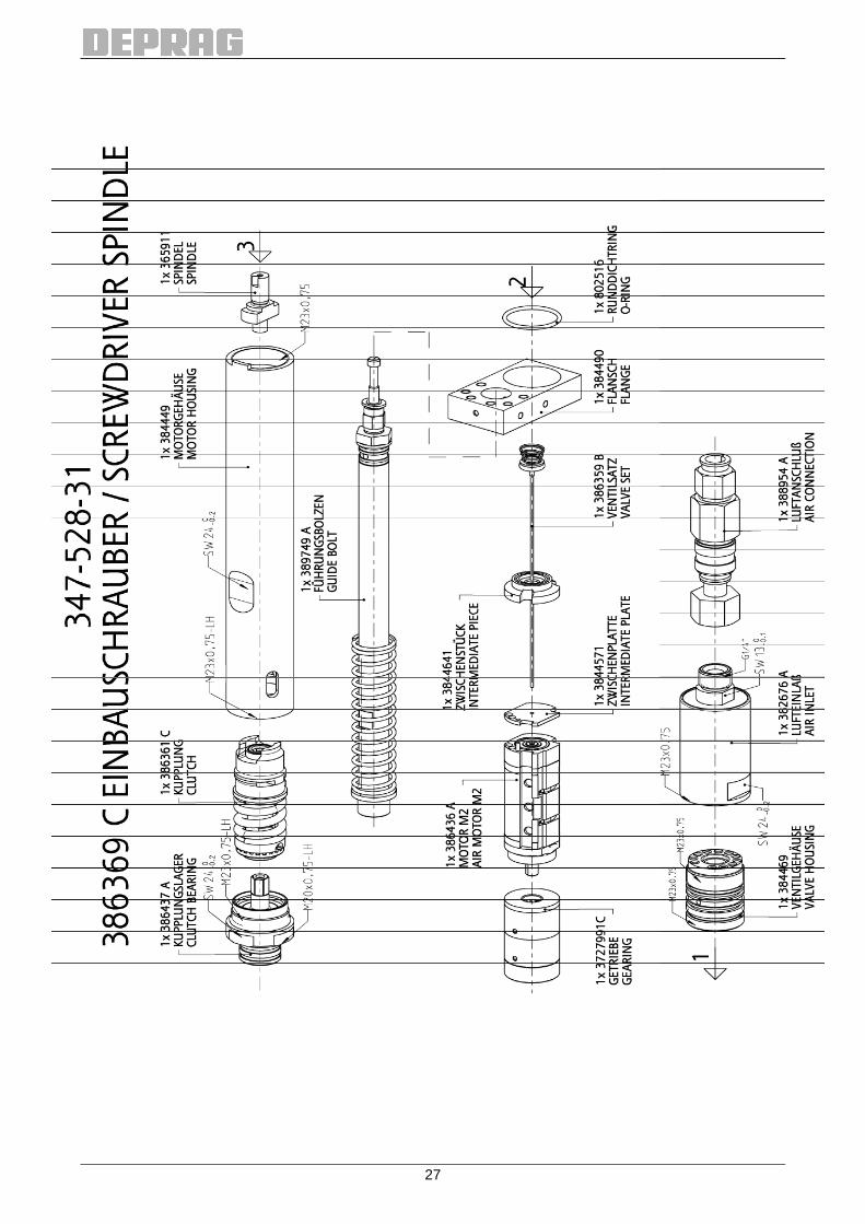
27

28
When ordering spare parts, the following is applica ble: In case you want a completely mounted gearing, please order the appropri-ate spindle additionally. Example for type 347-228-31: Gearing 3727991G + Spindle 3659112

29
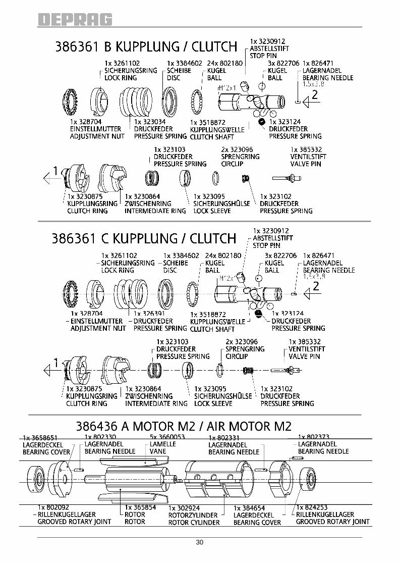
30
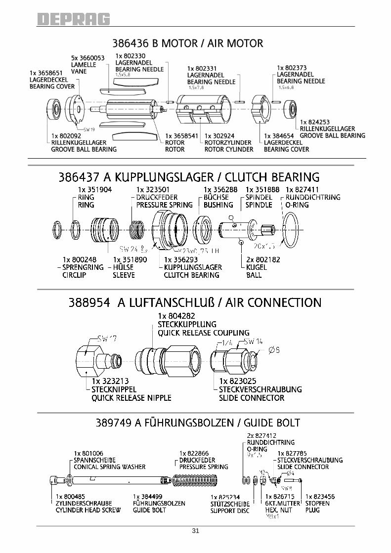
31
32
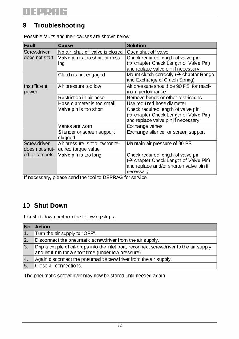
9 Troubleshooting
Possible faults and their causes are shown below:
Fault Cause Solution No air, shut-off valve is closed Open shut-off valve Valve pin is too short or miss-ing
Check required length of valve pin (� chapter Check Length of Valve Pin) and replace valve pin if necessary
Screwdriver does not start
Clutch is not engaged Mount clutch correctly (� chapter Range and Exchange of Clutch Spring)
Air pressure too low Air pressure should be 90 PSI for maxi-mum performance
Restriction in air hose Remove bends or other restrictions Hose diameter is too small Use required hose diameter Valve pin is too short Check required length of valve pin
(� chapter Check Length of Valve Pin) and replace valve pin if necessary
Vanes are worn Exchange vanes
Insufficient power
Silencer or screen support clogged
Exchange silencer or screen support
Air pressure is too low for re-quired torque value
Maintain air pressure of 90 PSI Screwdriver does not shut-off or ratchets Valve pin is too long Check required length of valve pin
(� chapter Check Length of Valve Pin) and replace and/or shorten valve pin if necessary
If necessary, please send the tool to DEPRAG for service.
10 Shut Down
For shut-down perform the following steps:
No. Action 1. Turn the air supply to “OFF”. 2. Disconnect the pneumatic screwdriver from the air supply. 3. Drip a couple of oil-drops into the inlet port, reconnect screwdriver to the air supply
and let it run for a short time (under low pressure). 4. Again disconnect the pneumatic screwdriver from the air supply. 5. Close all connections.
The pneumatic screwdriver may now be stored until needed again.
33
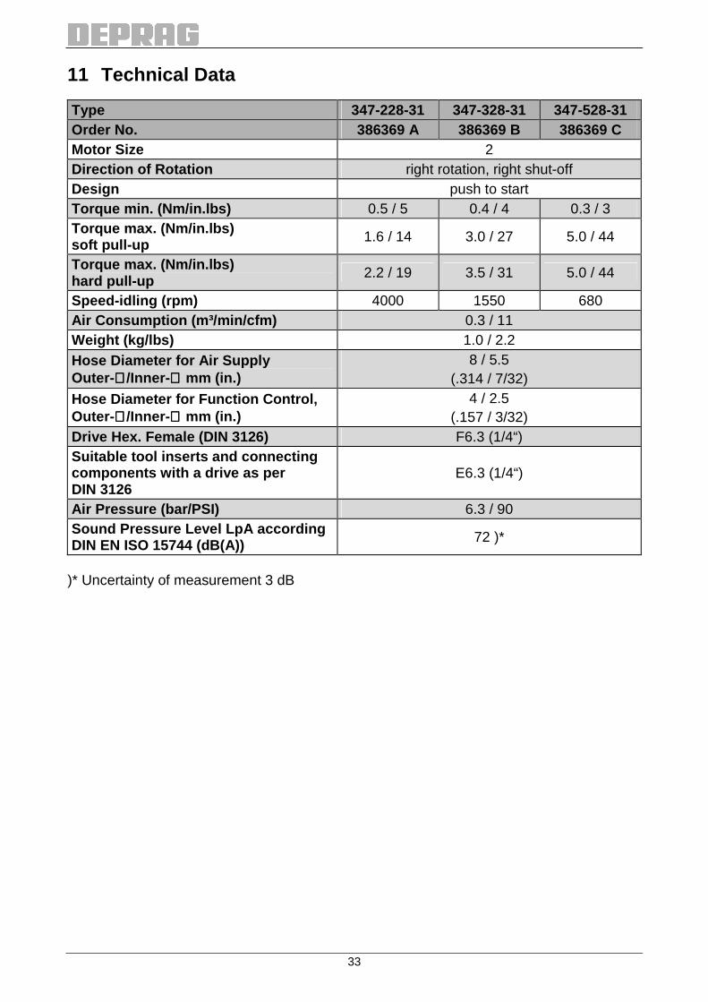
11 Technical Data
Type 347-228-31 347-328-31 347-528-31 Order No. 386369 A 386369 B 386369 C Motor Size 2 Direction of Rotation right rotation, right shut-off Design push to start Torque min. (Nm/in.lbs) 0.5 / 5 0.4 / 4 0.3 / 3 Torque max. (Nm/in.lbs) soft pull-up 1.6 / 14 3.0 / 27 5.0 / 44
Torque max. (Nm/in.lbs) hard pull-up 2.2 / 19 3.5 / 31 5.0 / 44
Speed-idling (rpm) 4000 1550 680 Air Consumption (m³/min/cfm) 0.3 / 11 Weight (kg/lbs) 1.0 / 2.2 Hose Diameter for Air Supply Outer- ∅∅∅∅/Inner- ∅∅∅∅ mm (in.)
8 / 5.5 (.314 / 7/32)
Hose Diameter for Function Control, Outer- ∅∅∅∅/Inner- ∅∅∅∅ mm (in.)
4 / 2.5 (.157 / 3/32)
Drive Hex. Female (DIN 3126) F6.3 (1/4“) Suitable tool inserts and connecting components with a drive as per DIN 3126
E6.3 (1/4“)
Air Pressure (bar/PSI) 6.3 / 90 Sound Pressure Level LpA according DIN EN ISO 15744 (dB(A)) 72 )*
)* Uncertainty of measurement 3 dB

34
12 EC-Declaration of Incorporation
EC-Declaration of Incorporation in accordance with the EC Machinery Directive 2006/42/EC, Annex IIB
As manufacturer of the partly completed machine we declare that:
• the specified machine corresponds to the listed essential requirements of the Directive 2006/42/EC, where applicable the other Directives and Standards, listed below.
• the relevant technical documentation is compiled in accordance with part B of Annex VII. • the relevant technical documentation in accordance with part B of Annex VII will be transmitted
in response to a reasonable request by the national authorities in printed form or in electronic form (pdf).
Manufacturer DEPRAG SCHULZ GMBH u. CO. P.O. Box 1352, D-92203 Amberg Kurfürstenring 12 – 18, D-92224 Amberg Authorized Person Mr. Josef Bock, address see manufacturer for Documentation Name STATIONARY SREWDRIVER SPINDLE
Machine Type _________________________________________________________ Serial Number _________________________________________________________ Year of Manufacture _________________________________________________________
Directives Date Applied and fulfilled essential requirements 2006/42/EC 2006-06 1.1.2, 1.1.5, 1.3.4, 1.5.3, 1.7.3, 1.7.4 Standards Date Remark DIN EN ISO 12100-1 2004-04 partly fulfilled DIN EN ISO 12100-2 2004-04 partly fulfilled
This partly completed machinery must not be put into service until the final machinery into which it is to be incorporated has been declared in conformity with the provisions of the Directive 2006/42/EC, where appropriate. Amberg, 6/17/2011

35
13 Service Locations and Authorized Partners
Contact persons in Germany
as well as
contact persons worldwide
can be found on our web site
www.deprag.com

DEPRAG SCHULZ GMBH u. CO. P.O. Box 1352, D-92203 Amberg Kurfürstenring 12-18, D-92224 Amberg � (09621) 371-0 Fax: (09621) 371-120 Internet: http://www.deprag.com e-mail: [email protected] Ju
n-1
1
Tec
hnic
al a
ltera
tions
and
err
ors
rese
rve
d