operating bulletin - alicat scientific, inc. alicat modbus operating bulletin modbus is an...
TRANSCRIPT

The Fastest Flow Controller Company in the World!
Operating Bulletin
MODBUS-RTU & MODBUS-TCP/IP

9/15/2017 Rev.6 DOC-MAN-MODBUS
RECALIBRATIONYour Alicat instrument is a precision device and Alicat strongly recommends that you send it to us on a yearly basis for recalibration.
A yearly recalibration does a few things:
► It insures that your unit is functioning according to specification.
► Contamination may cause the instrument to measure flow improperly. Recalibration insures the instrument is clean and free from debris.
► Recalibration maintains your LIFETIME WARRANTY!
Sending your unit for recalibration is easy and inexpensive. Recalibrations are usually shipped within five days of receipt, so it’s fast too.
Please keep the original box to return your Alicat instrument for recalibration.
ACCESSORIESNow that you have your Alicat instrument are you sure you’ve got everything you need? Alicat accessories can make your job easier.
Many of our customers also order:
► Power Supplies — A universal wall power supply that makes it easy to power your Alicat unit just about anywhere in the world.
► BB9 — Alicat’s multi-drop box that allows easy connection of up to nine Alicat instruments to a single USB, RS-232 or RS-485 port.
► MD8DB9 — An RS-232 to 8 pin Mini-DIN cable to connect your Alicat instrument to a computer. A variety of other cables are also available.
► Flow Vision™ SC — A GUI based Windows®program that allows easy computer access and control for one or multiple Alicat instruments.
► Fittings and filters — Keep your instrument properly connected to your process and free from harmful contamination.
FULL TECHNICAL SUPPORT | LIFETIME WARRANTY

3
ALICAT MODBUS OPERATING BULLETINModbus is an application layer messaging protocol that formats data for communications among industrial devices. Alicat supports both Modbus-RTU and Modbus TCP/IP protocols depending on the device configuration.Devices ordered with the Modbus-RTU application layer communicate over serial RS-232 or RS-485. Modbus data is transmitted through Alicat’s default 8-pin mini-DIN connector, a 9-pin or 15-pin D-Sub connector or an RJ45 connector. Note: An RJ45 connecter in a Modbus-RTU device does not indicate support of Ethernet communication or availability of the Modbus-TCP/IP protocol in this unit. In addition to Modbus-RTU support, your device supports standard Alicat serial commands. Please see your operating manual for a description of the supported commands.Devices ordered with Modbus-TCP/IP support include a dual-RJ45 connector that supports standard 10BaseT & 100BaseT Ethernet communication. See section 3 for information on setting the device’s network configuration.

4
1 Modbus RegistersAlicat’s deployment of Modbus uses a Master/Slave structure that organizes data into 16-bit registers. Alicat supports Modbus function codes 03 “Read Holding Registers,” 04 “Read Input Registers” and 16 “Write Multiple Registers.”Alicat devices use the Modbus PLC numbering convention such that all registers begin at index 1. The values seen in a Modbus Protocol Data Unit are zero based and would be one less than those specified below. If your master controller does not follow this convention, you may need to decrement register addresses by one.All 32-bit values are handled in consecutive Modbus registers in big-endian format. This means bits 31:16 are in the lower numbered Modbus register and bits 15:0 are in the higher register. All floating-point values are IEEE 32-bit floats.
Parameter Access Register Number
Description
Command ID RW 1000 See Section 1.1Command Argument RW 1001Setpoint W 1010-1 See Section 1.2Mixture Gas 1 Index RW 1050 See Section 1.3Mixture Gas 1 Pct RW 1051Mixture Gas 2 Index RW 1052Mixture Gas 2 Pct RW 1053Mixture Gas 3 Index RW 1054Mixture Gas 3 Pct RW 1055Mixture Gas 4 Index RW 1056Mixture Gas 4 Pct RW 1057Mixture Gas 5 Index RW 1058Mixture Gas 5 Pct RW 1059Gas Number R 1200 See your Alicat
operating manual for a list of gas numbers
Device Status R 1201-02 See Section 1.4Device Statistic 1 Value R 1203-04Device Statistic 2 Value R 1205-06Device Statistic 3 Value R 1207-08Device Statistic 20 Value
R 1241-42
5
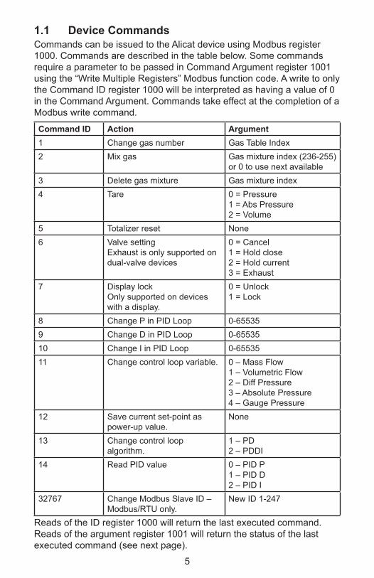
1.1 Device CommandsCommands can be issued to the Alicat device using Modbus register 1000. Commands are described in the table below. Some commands require a parameter to be passed in Command Argument register 1001 using the “Write Multiple Registers” Modbus function code. A write to only the Command ID register 1000 will be interpreted as having a value of 0 in the Command Argument. Commands take effect at the completion of a Modbus write command.
Command ID Action Argument1 Change gas number Gas Table Index2 Mix gas Gas mixture index (236-255)
or 0 to use next available3 Delete gas mixture Gas mixture index4 Tare 0 = Pressure
1 = Abs Pressure2 = Volume
5 Totalizer reset None6 Valve setting
Exhaust is only supported on dual-valve devices
0 = Cancel1 = Hold close2 = Hold current3 = Exhaust
7 Display lockOnly supported on devices with a display.
0 = Unlock1 = Lock
8 Change P in PID Loop 0-655359 Change D in PID Loop 0-6553510 Change I in PID Loop 0-6553511 Change control loop variable. 0 – Mass Flow
1 – Volumetric Flow2 – Diff Pressure3 – Absolute Pressure4 – Gauge Pressure
12 Save current set-point as power-up value.
None
13 Change control loop algorithm.
1 – PD2 – PDDI
14 Read PID value 0 – PID P1 – PID D2 – PID I
32767 Change Modbus Slave ID – Modbus/RTU only.
New ID 1-247
Reads of the ID register 1000 will return the last executed command. Reads of the argument register 1001 will return the status of the last executed command (see next page).

6
Command status returns in register 1001 are as follows:
Status Description0 Success236-255 Gas mix index that was created or updated (Mix gas
command only)0x8001 Invalid command ID0x8002 Invalid setting0x8003 Requested feature is unsupported0x8004 Invalid gas mix index0x8005 Invalid gas mix constituent0x8006 Invalid gas mix percentage
1.2 SetpointThe device setpoint should be sent as a 32-bit IEEE floating point value. Setpoint values must be sent together in a Write Multiple Registers command. Any writes to only one half of the setpoint value will cause an error. Setpoint is ignored on devices without a controller.
1.3 Gas MixingGas mixing can be performed with 2-5 gases using the mix registers 1050-1059. The mix is a two-step process. First, the desired constituent gas indexes and percentages must be written to the mix registers followed by a write of the Mix Gas command (ID 2) into command register 1000 (with the command argument being optional).Gas mix percentages are interpreted as integer hundredths of a percent and the total percentage must sum to 100%. For example, to specify a mix of 50%, a value of 5000 should be written into the gas percentage register. The mix will be performed with the first N gases that have a non- zero percentage. As an example, if you wish to mix 3 gases, you would write the index and percentage for those gases into registers 1050-1055 and write a value of zero into 1057-1059.If the command argument passed to the mix command is 0 or is omitted, a new gas mix index will be allocated in the next empty gas mix index starting at 255 and working down to 236. If no user mix indices are unused, the command will not be successfully completed and an error will be returned in the command argument register.If the command argument passed is between 236 and 255, the mixture with the specified index will be either created or updated to the new composition. If the specified index is not valid (the command argument is neither 0 nor 236-255), an error will be returned.

7
Upon completion of mixing, the command argument register will be updated with the mix result. If the mix was valid, the index of the mixed gas will be returned. If one of the requested mix gas constituents did not exist or the percentage does not add to 100%, an error value will be returned and the mix will not be created.
Note: Gas mixing is only available over the Modbus serial interface and cannot be performed from the front panel display.
All gas mixtures are accessible via Gas Select on the front panel, but mixtures may not be created or deleted via the front panel.
1.4 Device StatusThis register specifies status conditions in the device. The value in parenthesis is the front-panel display of the corresponding condition.
Bit Description0 Temperature Overflow (TOV)1 Temperature Underflow (TOV)2 Volumetric Overflow (VOV)3 Volumetric Underflow (VOV)4 Mass Overflow (MOV)5 Mass Underflow (MOV)6 Pressure Overflow (POV)7 Totalizer Overflow (OVR)8 PID Loop in Hold (HLD)9 ADC Error (ADC)10 PID Exhaust (EXH)11 Over pressure limit (OPL)12 Flow overflow during totalize (TMF)13 Measurement was aborted
1.5 Device StatisticsYour Alicat device can output 20 different configurable data statistics. The default statistics for each device type are specified in the sections below. For Modbus-RTU devices, the actual statistic and units output on your device can be determined by issuing the Alicat data frame query command (*??D*). For Modbus-TCP/IP, the available statistics are viewable from the device’s embedded webserver. To access, point your web browser to the device’s IP address and select the Data I/O tab.If you wish to customize the output of your device please speak to an Alicat applications engineer.

8
Unless specified below, all output values are in 32-bit IEEE floating point. If an unused device statistic slot is read on Modbus-RTU, the value 0xFFFFFFFF will be returned. On Mobus-TCP/IP devices unused slots will return an invalid register address error.The value returned for a pressure reading can be absolute pressure, gauge pressure or differential pressure depending on your device’s configuration.
1.5.1 Mass Flow ControllerRegister Number Statistic1203-04 Pressure1205-06 Flow Temperature1207-08 Volumetric Flow1209-10 Mass Flow1211-12 Mass Flow Setpoint1213-14 Mass Total*
* Mass Total is only available on units with the Totalizer option.
1.5.2 Mass Flow MeterRegister Number Statistic1203-04 Pressure1205-06 Flow Temperature1207-08 Volumetric Flow1209-10 Mass Flow1211-12 Mass Total*
* Mass Total is only available on units with the Totalizer option.
1.5.3 Pressure GaugeRegister Number Statistic1203-04 Pressure
1.5.4 Pressure ControllerRegister Number Statistic1203-04 Pressure1205-06 Pressure Setpoint
9
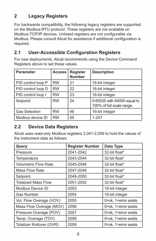
2 Legacy Registers
For backwards compatibility, the following legacy registers are supported on the Modbus-RTU protocol. These registers are not available on Modbus-TCP/IP devices. Unlisted registers are not configurable via Modbus. Please consult Alicat for assistance if additional configuration is required.
2.1 User-AccessibleConfigurationRegistersFor new deployments, Alicat recommends using the Device Command Registers above to set these values.
Parameter Access Register Number
Description
PID control loop P RW 21 16-bit integerPID control loop D RW 22 16-bit integerPID control loop I RW 23 16-bit integerSetpoint RW 24 0-65535 with 64000 equal to
100% of full scale range.Gas Selection RW 46 16-bit integerModbus device ID RW 65 1-247
2.2 Device Data RegistersAlicat uses read-only Modbus registers 2,041-2,059 to hold the values of the instrument data as follows:
Query Register Number Data TypePressure 2041-2042 32-bit float*Temperature 2043-2044 32-bit float*Volumetric Flow Rate 2045-2046 32-bit float*Mass Flow Rate 2047-2048 32-bit float*Setpoint 2049-2050 32-bit float*Totalized Mass Flow 2051-2052 32-bit float*Modbus Device ID 2053 16-bit integerGas Number 2054 16-bit integerVol. Flow Overage (VOV) 2055 0=ok, 1=error existsMass Flow Overage (MOV) 2056 0=ok, 1=error existsPressure Overage (POV) 2057 0=ok, 1=error existsTemp. Overage (TOV) 2058 0=ok, 1=error existsTotalizer Rollover (OVR) 2059 0=ok, 1=error exists

10
3Modbus-TCP/IPConfigurationAlicat Modbus-TCP/IP devices have two 10/100Mbps Ethernet ports with an embedded switch. Either port can be used to communicate with the device. In addition, the embedded switch supports packet forwarding allowing daisy-chaining devices in a linear or ring topology.3.1IPAddressConfigurationThe out-of-the-box configuration of your device is to use DHCP to obtain an IP address. There is an embedded web server in the device which supports assigning a static IP address to the device. To do so, you must first assign an address using DHCP.The following shows an example of configuring the address using Microsoft Windows:First, assign a static IP to an unused network interface:

11
Second, configure a DHCP server to give a known IP address to your device on the static network. This example uses the open source Tftpd64 tool (http://tftpd32.jounin.net):

12
After connecting your Alicat device directly to the static port and supplying power to the device, you should see an address allocated to the device by the DHCP server:
The network configuration can then be changed using the device’s embedded webserver. Navigate to the Network Config tab, uncheck the “Use DHCP” box, and enter the desired static IP address into the form.

13
This page left intentionally blank.

14
This page left intentionally blank.

Notice: Alicat Scientific, Inc. reserves the right to make any changes and improvements to the products described in this manual at any time and without notice. This manual is copyrighted. This document may not, in whole or in part, be copied, reproduced, translated, or converted to any electronic medium or machine readable form, for commercial purposes, without prior written consent from the copyright holder.Note: Although we provide assistance on Alicat Scientific products both personally and through our literature, it is the complete responsibility of the user to determine the suitability of any product to their application.
Limited Lifetime WarrantyAlicat Scientific, Inc. warrants to the original purchaser (hereinafter referred to as “Buyer”) that instruments manufactured by Alicat Scientific (hereinafter referred to as “Product”) shall be free from defects in materials and workmanship for the life of the Products.Under this warranty, the Products will be repaired or replaced at manufacturer’s option, without charge for parts or labor when the Product is carried or shipped prepaid to the factory together with proof of purchase.The foregoing shall constitute the exclusive and sole remedy in lieu of other remedies of the Buyer for any breach by Alicat Scientific of this warranty to the maximum extent permitted by law.This warranty does not apply to any Product which has not been installed or used in accordance with the Product operation and installation specifications provided to Buyer verbally or in writing by Alicat Scientific for the proper and normal use of the Product.Buyer agrees hereunder that Alicat reserves the right to void any warranty, written or implied, if upon Alicat’s examination of Product shall disclose to Alicat’s satisfaction that the Product failure was due solely, or in part, to accident, misuse, neglect, abuse, alteration, improper installation, unauthorized repair or improper testing by Buyer or agent of Buyer.Alicat Scientific shall not be liable under any circumstances for indirect, special, consequential, or incidental damages in connection with, or arising out of, the sale, performance, or use of the Products covered by this warranty.Alicat Scientific does not recommend, warrant or assume responsibility for the use of the Products in life support applications or systems.Alicat’s warranties as herein above set forth shall not be enlarged, diminished or affected by, and no obligation or liability shall arise or grow out of Alicat’s rendering of technical advice in connection with Buyer’s order of the Products furnished hereunder.If Product becomes obsolete, Alicat Scientific, at its own discretion, reserves the right to repair the Product with available replacement parts or upgrade the Product to a current, commercially available version of the original Product. Should upgrading the Product be deemed necessary by Alicat, Buyer hereby agrees to pay an upgrade fee equal to seventy percent of the retail value of the replacement Product. Alicat Scientific hereunder makes no claim that replacement Products will look, function or operate in the same or similar manner as the original product.When a Product is returned to Alicat Scientific for recalibration this service is considered normal preventative maintenance. Recalibration of Product shall not be treated as a warranty service unless recalibration of Product is required as the result of repairs to Product pursuant to this Warranty. Failure of Buyer to send Product to Alicat Scientific for recalibration on a yearly basis after a period of 36 months from date of manufacture will remove any and all obligations regarding repair or replacement of Product as outlined by this Warranty to Buyer from Alicat Scientific.This Warranty is in lieu of all other relevant warranties, expressed or implied, including the implied warranty of merchantability and the implied warranty of fitness for a particular purpose, and any warranty against infringement of any patent.Continued use or possession of Products after expiration of the applicable warranty period stated above shall be conclusive evidence that the warranty is fulfilled to the full satisfaction of Buyer. Alicat makes no warranty as to experimental, non-standard or developmental Products.Accessories purchased from Alicat are not covered by this warranty.
Conformity / Supplemental Information:The product complies with the requirements of the Low Voltage Directive 2006/95/EC and the EMC Directive 2004/108/EC and carries the CE Marking accordingly. Contact the manufacturer for more information.
If you would like additional information regarding the use of this product, please contact:Alicat Scientific, Inc.
7641 N Business Park DriveTucson, Arizona 85743
USAPhone: 520-290-6060
Fax: 520-290-0109Email: [email protected]
Website: www.alicat.com

Alicat.com
The Fastest Flow
Controller C
ompany in the W
orld!
#G
asA
bsoluteViscosity*
25°C
Density **25°C
14.696PSIA
Com
pressibility 25°C
14.696PSIA0
Air
Air
184.9181.1840
0.99971
Argon
Ar
225.5931.6339
0.99942
Methane
CH
4111.852
0.65690.9982
3C
arbon Monoxide
CO
176.4731.1453
0.99974
Carbon D
ioxide C
O2
149.3321.8080
0.99495
Ethane C
2H6
93.5401.2385
0.99246
Hydrogen
H2
89.1530.08235
1.00067
Helium
H
e198.457
0.163531.0005
8N
itrogen N
2178.120
1.14530.9998
9N
itrous Oxide
N2O
148.4561.8088
0.994610
Neon
Ne
311.1490.8246
1.000511
Oxygen
O2
204.5911.3088
0.999412
Propane C
3H8
81.4581.8316
0.984113
normal-B
utane n-C
4H10
74.0522.4494
0.969914
Acetylene
C2H
2104.448
1.07200.9928
15Ethylene
C2H
4103.177
1.15330.9943
16iso-B
utane i-C
4H10
74.9882.4403
0.972817
Krypton
Kr
251.3423.4274
0.999418
Xenon Xe
229.7855.3954
0.994719
SulfurHexafluoride
SF6153.532
6.03800.9887
#G
asA
bsoluteViscosity*
25°C
Density **25°C
14.696PSIA
Com
pressibility 25°C
14.696PSIA20
75%A
r / 25% C
O2
C-25
205.6151.6766
0.998721
90% A
r / 10% C
O2
C-10
217.5291.6509
0.999122
92% A
r / 8% C
O2
C-8
219.1341.6475
0.999223
98% A
r / 2% C
O2
C-2
223.9731.6373
0.999324
75% C
O2 / 25%
Ar
C-75
167.4511.7634
0.996625
75% A
r / 25% H
eH
E-75230.998
1.26600.9997
2675%
He / 25%
Ar
HE-25
234.3060.5306
1.0002
2790%
He / 7.5%
Ar /
2.5% C
O2
Helistar®
A1025
A1025
214.8400.3146
1.0003
2890%
Ar / 8%
CO
2 / 2%
O2
Stargon® C
SStar29
218.8171.6410
0.9992
2995%
Ar / 5%
CH
4P-5
223.4831.5850
0.9993*in m
icropoise (1 Poise = gram / (cm
) (sec)) **Gram
s/Liter R
eference: NIST R
EFPRO
P 7 Database
SCFM
1.00=
28.3160SLPM
SLPM100.00
=3.5316
SCFM
SCFH
1.00=
0.4719SLPM
SLPM100.00
=211.9093
SCFH
SCIM
100.00=
1.6390SLPM
SLPM1.00
=61.0128
SCIM
SCIH
1000.00=
0.2732SLPM
SLPM1.00
=3660.7688
SCIH
Gas V
iscosity, Density and C
ompressibility:
Flow C
onversions:7641 N
Business Park D
riveTucson A
Z 85743 USA
Phone: 888-290-6060 Fax: 520-290-0109