operating and maintenance...
TRANSCRIPT

This document is the property of ECA ROBOTICS SAS Montpellier. Its content must not be reproduced or revealed without authorisation
S.A. au capital de 17 556 021 Euros - R.C. Montpellier 2011B2678 - N°Siret : 509 232 591 00057 translation LRO 21/06/12 501, rue de la Croix de Lavit B.P. 4403 - 34197 MONTPELLIER CEDEX 5 - FRANCE
TEL +33(0)4 67 63 64 00 • FAX +33 (0)4 67 52 14 88
E-mail [email protected] Web http://www.ecahytec.com
OPERATING AND MAINTENANCE MANUAL
ARM 5E MICRO 5 Function Electric Manipulator ARM
(Joystick USB Surface Controller)
Reference : MUE00647GBB-1

OPERATING AND MAINTENANCE MANUAL
ARM 5E MICRO ELECTRIC ARM (Joystick USB Surface Controller)
Reference
MUE00647GBB-1
Mue00647GBB-1 2 / 13
1. UP DATE CHART
ISSUE SUBJECT ORIGINATOR VERIFICATION APPROVAL
Draft A Draft Issue KD BJ PS
Issue A KD BJ BJ
Issue B UP-DATING
20/03/2013
HVE AMA/FCA JMV
CONTENTS
1. UP DATE CHART ........................................................................................................ 2
2. INTRODUCTION .......................................................................................................... 3
3. SPECIFICATION .......................................................................................................... 3
4. DESCRIPTION ............................................................................................................. 4
5. ELECTRICAL CONNECTIONS ................................................................................... 8
6. OPERATING PROCEDURE ...................................................................................... 11
7. TROUBLESHOOTING ............................................................................................... 12
8. CONTACTS ............................................................................................................... 13
9. GUARANTEE EXTENT ............................................................................................. 13
10. TECHNICAL ASSISTANCE................................................................................... 13
11. APPENDICES ......................................................................................................... 13

OPERATING AND MAINTENANCE MANUAL
ARM 5E MICRO ELECTRIC ARM (Joystick USB Surface Controller)
Reference
MUE00647GBB-1
Mue00647GBB-1 3 / 13
2. INTRODUCTION
This Equipment has been made in compliance with CE marking Standards.
This manual is written for suitably qualified personnel responsible for operation and maintenance of this equipment. Operating and maintaining must be done according to appropriate general rules. Non appropriate or defective use may lead to an irreversible failure of components or the equipment. If any failure occurs, the user must check that the device is safe for its environment.
Before every operation, the operator must check that the system is correctly configured in accordance with this manual.
CAUTION: REPAIRING THE EQUIPMENT WHILE SWITCHED ON IS RESERVED TO QUALIFIED
TECHNICIANS
3. SPECIFICATION
SLEW 120 DEGREES ELEVATE 90 DEGREES ELBOW 132 DEGREES JAW ROTATE CONTINUOUS JAW OPENING 125mm at the tips REACH 640mm (from the Slew pivot) LIFT 10Kg at 0.5 Amps at full extension JAW ROTATE TORQUE >10Nm at 2 Amps JAW CLOSING FORCE >50Kg at 2 Amps JAW ROTATE SPEED ~ 60 RPM at 24vdc WEIGHT 6Kg Total mass in fresh water 2.2Kg Mobile mass in fresh water 15Kg in air SUPPLY 20 - 28vdc 100 - 240vac DEPTH 3000 METRES

OPERATING AND MAINTENANCE MANUAL
ARM 5E MICRO ELECTRIC ARM (Joystick USB Surface Controller)
Reference
MUE00647GBB-1
Mue00647GBB-1 4 / 13
4. DESCRIPTION
4.1 System Components
The five function Electric Arm 5E Micro consists of five major components, these are:-
a) Surface Control Unit. b) SubSea Electronics Housing. c) Computer d) The Manipulator Arm. e) Compensation
4.2 Surface Electronics
The Arm can either be controlled by the Joystick USB Surface Controller or from the controlComputer The Joystick USB Surface Controller is powered only when plugged into the USB port of the Computer. The Surface Control Unit illustrated below is the typical standard version. Custom designs can be supplied to suit customer requirements where size or configuration needs to be changed to suit the installation.
Photo 1
(Joystick USB Surface Contoller)

OPERATING AND MAINTENANCE MANUAL
ARM 5E MICRO ELECTRIC ARM (Joystick USB Surface Controller)
Reference
MUE00647GBB-1
Mue00647GBB-1 5 / 13
The Manipulator arm is controlled via the Joystick, the Joystick Toggle and the Jaw Grip switch (Positioned above the Joystick). The following movements of the Manipulator Arm in relation to the Surface Control Unit demands will occur and are proportional to the level of demand by the operator.
Photo 2
(Joystick and Jaw controls)
4.2.1 Demands
Joystick pulled back (towards the operator) - Shoulder up. Joystick pushed forward (away from the operator) - Shoulder down. Joystick moved to the left - Slew left. Joystick moved to the right - Slew right. Toggle depressed back - Elbow up. Toggle depressed forward – Elbow down. Toggle depressed left – Jaw rotates to the left (counterclockwise). Toggle depressed right - Jaw rotates to the right (clockwise). Jaw Grip pushed away from the operator – Jaws open. Jaw Grip pulled towards the operator – Jaws close.
4.2.1 Computer Controller
The Computer with this system has the following Key features:- - Windows 7 Starter Edition - 1GB Memory - 32 Bit - 320GB Storage The Control System used within this Computer for driving the Arm and programming the control parameters are contained within Appendix A1.

OPERATING AND MAINTENANCE MANUAL
ARM 5E MICRO ELECTRIC ARM (Joystick USB Surface Controller)
Reference
MUE00647GBB-1
Mue00647GBB-1 6 / 13
Communications system diagram
DSP = Digital signal processor, used as main processor in Motor driver and converter card. MCP2551 = CAN bus transceiver used in conjunction with DSP above MAX3292 = RS485 transceiver used in conjunction with DSP above
Computer
Converter Card (RS485-CAN bus)
dspic33fj256mc710
mcp2551 Max3292
Motor 4 Dsp mcp2551
-
Motor 5
Dsp mcp2551
Motor 1 Dsp mcp2551
Motor 3 Dsp mcp2551
Motor 2 Dsp mcp2551
CAN bus
RS485 Test Cable (Provided)
Joystick USB
USB to RS485
SubSea Housing
Surface Electronics
USB
OPERATING AND MAINTENANCE MANUAL
ARM 5E MICRO ELECTRIC ARM (Joystick USB Surface Controller)
Reference
MUE00647GBB-1
Mue00647GBB-1 7 / 13
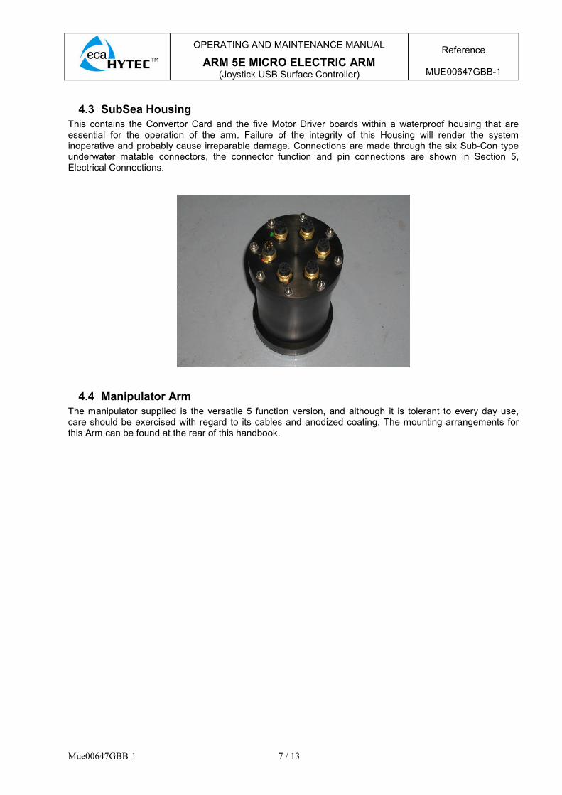
4.3 SubSea Housing
This contains the Convertor Card and the five Motor Driver boards within a waterproof housing that are essential for the operation of the arm. Failure of the integrity of this Housing will render the system inoperative and probably cause irreparable damage. Connections are made through the six Sub-Con type underwater matable connectors, the connector function and pin connections are shown in Section 5, Electrical Connections.
4.4 Manipulator Arm
The manipulator supplied is the versatile 5 function version, and although it is tolerant to every day use, care should be exercised with regard to its cables and anodized coating. The mounting arrangements for this Arm can be found at the rear of this handbook.
OPERATING AND MAINTENANCE MANUAL
ARM 5E MICRO ELECTRIC ARM (Joystick USB Surface Controller)
Reference
MUE00647GBB-1
Mue00647GBB-1 8 / 13
5. ELECTRICAL CONNECTIONS
5.1 Electrical connections are made to the SubSea Housingvia Sub-Con typeconnectors for each of the arm functions, power and communications. These have been orientated and identified so that the possibility of incorrect connection has been reduced.
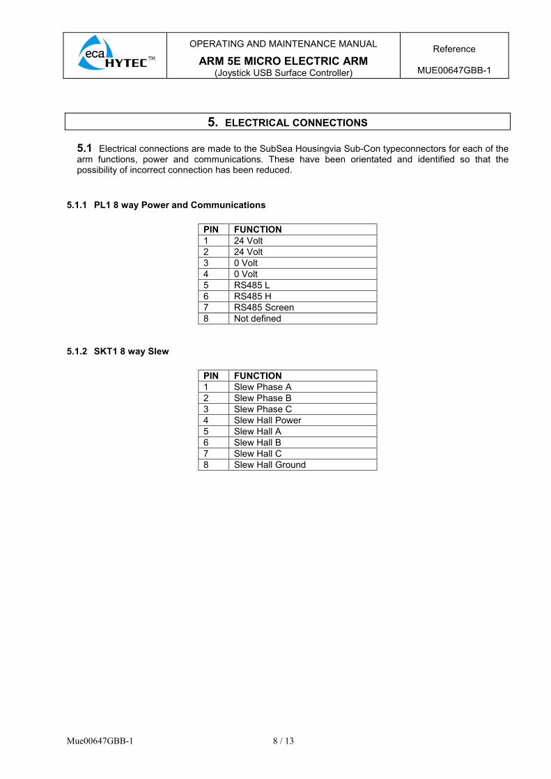
5.1.1 PL1 8 way Power and Communications
PIN FUNCTION
1 24 Volt
2 24 Volt
3 0 Volt
4 0 Volt
5 RS485 L
6 RS485 H
7 RS485 Screen
8 Not defined
5.1.2 SKT1 8 way Slew
PIN FUNCTION
1 Slew Phase A
2 Slew Phase B
3 Slew Phase C
4 Slew Hall Power
5 Slew Hall A
6 Slew Hall B
7 Slew Hall C
8 Slew Hall Ground

OPERATING AND MAINTENANCE MANUAL
ARM 5E MICRO ELECTRIC ARM (Joystick USB Surface Controller)
Reference
MUE00647GBB-1
Mue00647GBB-1 9 / 13
5.1.3 SKT2 8 way Elbow
PIN FUNCTION
1 Elbow Phase A
2 Elbow Phase B
3 Elbow Phase C
4 Elbow Hall Power
5 Elbow Hall A
6 Elbow Hall B
7 Elbow Hall C
8 Elbow Hall Ground
5.1.4 SKT3 8 way Jaw Rotate
PIN FUNCTION
1 Jaw Rotate Phase A
2 Jaw Rotate Phase B
3 Jaw Rotate Phase C
4 Jaw Rotate Hall Power
5 Jaw Rotate Hall A
6 Jaw Rotate Hall B
7 Jaw Rotate Hall C
8 Jaw Rotate Hall Ground
5.1.5 SKT4 8 way Jaw Close
PIN FUNCTION
1 Jaw Rotate Phase A
2 Jaw Rotate Phase B
3 Jaw Rotate Phase C
4 Jaw Rotate Hall Power
5 Jaw Rotate Hall A
6 Jaw Rotate Hall B
7 Jaw Rotate Hall C
8 Jaw Rotate Hall Ground
OPERATING AND MAINTENANCE MANUAL
ARM 5E MICRO ELECTRIC ARM (Joystick USB Surface Controller)
Reference
MUE00647GBB-1
Mue00647GBB-1 10 / 13
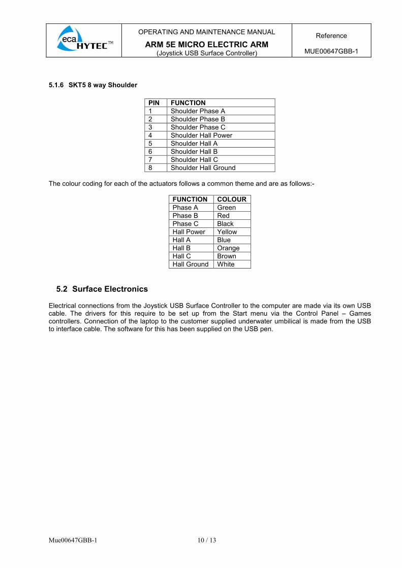
5.1.6 SKT5 8 way Shoulder
PIN FUNCTION
1 Shoulder Phase A
2 Shoulder Phase B
3 Shoulder Phase C
4 Shoulder Hall Power
5 Shoulder Hall A
6 Shoulder Hall B
7 Shoulder Hall C
8 Shoulder Hall Ground
The colour coding for each of the actuators follows a common theme and are as follows:-
FUNCTION COLOUR
Phase A Green
Phase B Red
Phase C Black
Hall Power Yellow
Hall A Blue
Hall B Orange
Hall C Brown
Hall Ground White
5.2 Surface Electronics
Electrical connections from the Joystick USB Surface Controller to the computer are made via its own USB cable. The drivers for this require to be set up from the Start menu via the Control Panel – Games controllers. Connection of the laptop to the customer supplied underwater umbilical is made from the USB to interface cable. The software for this has been supplied on the USB pen.

OPERATING AND MAINTENANCE MANUAL
ARM 5E MICRO ELECTRIC ARM (Joystick USB Surface Controller)
Reference
MUE00647GBB-1
Mue00647GBB-1 11 / 13
6. OPERATING PROCEDURE
6.1 General Safety
Before applying power to the system, ensure that all personnel and equipments are clear from the working parameters of the Arm. Ensure that when the Arm is in operation, all persons are not physically close to the moving Arm as serious injury may occur.
6.2 Electrical Connection (Test)
Connect the Arm to the SubSea housing as detailed in section 5.1 above. Connect the Power / Communications test cable (As supplied) to the SubSea housing. Connect a suitable 24Vdc supply to the Red (positive) and Black (negative) cables. A DC supply that is able to supply 3 amps will be sufficient to operate all of the Arms functions simultaneously. A schematic of the test cable is shown below.
Connect the Joystick USB Surface Controller and the Moxa U port into the computer, also connet the Moxa U port to the test lead before turning on the computer. The computer has been preloaded with all of the software required and will automatically boot to the correct programme. Turn on the 24vDC supply and the system is ready for use.
6.3 Operation
Detailed operation functions of the Joystick USB Surface Controller are set out in Para 4.2.1. For detailed computer operation please see Appendix A1.
OPERATING AND MAINTENANCE MANUAL
ARM 5E MICRO ELECTRIC ARM (Joystick USB Surface Controller)
Reference
MUE00647GBB-1
Mue00647GBB-1 12 / 13
7. TROUBLESHOOTING
7.1 The Manipulator appears disconnected
Check that the correct Port is being used. Check that the power is present and at the correct level. Check that the Communication cable is correctly attached and undamaged. Check the WindowsPort settings
7.2 Software Connectivity
This situation is unusual but can happen when an incorrect port number is selected. See device manager in windows for more information.
7.3 Slow Manipulators response
This usually happens when windows is busy, we suggest you uninstall all products not supplied with your windows installation. Please also check task manager to ensure no miscellaneous processes are stealing memory.
7.4 Communications
The following section describes the Comms/software details
• RS485
• 115200 baud rate.
• USB link, appears as COM port on PC, for details see windows device manger (control panel/System/hardware/Device Manager/Ports(COM & LPT)

OPERATING AND MAINTENANCE MANUAL
ARM 5E MICRO ELECTRIC ARM (Joystick USB Surface Controller)
Reference
MUE00647GBB-1
Mue00647GBB-1 13 / 13
8. CONTACTS
For Product and Technical Support please contact in the first instance:- SAV Montpellier : Tél : 33 (0) 4 67 63 64 00 Fax : 33 (0) 4 67 52 14 88 E-mail : [email protected] Web : www.ecahytec.com
9. GUARANTEE EXTENT
9.1 GENERALITIES
Refer to the general and specific conditions of the contract.
9.2 WARRANTY DURATION
The equipment is guaranteed (parts and labour) for a period of twelve months from the date of purchase.
10. TECHNICAL ASSISTANCE
See contract general and specific conditions related to technical assistance.
11. APPENDICES

OPERATING AND MAINTENANCE MANUAL
ARM 5E MICRO ELECTRIC ARM (Joystick USB Surface Controller)
Reference
MUE00647GBB-1
Mue00647GBA-1
A1 SOFTWARE DETAILS
The software can be split into 4 main sections
• Motor control panel
• Master Feedback
• COMS settings
• Joystick Settings

OPERATING AND MAINTENANCE MANUAL
ARM 5E MICRO ELECTRIC ARM (Joystick USB Surface Controller)
Reference
MUE00647GBB-1
Mue00647GBA-1
A1.1 Motor Control Panel
The motor control panel has 2 pages; Demand and PID.
A1.1.1 Demand Page
The demand page is the main control page, from this page the operator can see the feedback from the motor driver as well as adjust the controls. The various parts are described bellow.
A1.1.2 Force
Force is a display of the power consumed by the motor; it is for indication only and not calibrated to any meaningful units.
A1.1.3 Joystick bar and centre/enable joy
This functionality allows operation with or without a joystick attached to the PC. The user can use the on screen track bar to command the joint; the on screen track bar always has priority over the handheld joystick. The Centre/Enable Joy makes the Joystick USB Surface Controller active if connected and causes the track bar to always return centre, should you not want the Joystick USB Surface Controller active then disconnect it.
A1.1.4 Demand Type
In this mode you set the type of demand. Voltage mode sets the average voltage to the motor depending on joystick deflection (desired by human operators). Speed mode sets the Speed in RPM of the motor in a closed loop operation depending on joystick deflection (the end result is dependant on the gearbox ratios).
A1.1.5 Temperature
If the temperature on any sensor reaches more than 60° continue with caution especially if the underwater electronics housing is not in water to provide cooling.
A1.1.6 Current Limit DAC
This has been pre-set to a value of 50. This has been found to be the nominal figure whereby the Arm performs well. Lower values may be used, especially for more sensitive operations. Higher values may be used, however the operator must be aware the to higher value may cause damage to the Arm. This value is not scaled to any meaningful terms. It however allows a way to adjust the current supplied to any motor function, if the current needs to be limited to a given value, connect a calibrated amp meter to the manipulator, (carefully drive the actuator to the end of travel) and trim the DAC until you are within your power supply requirements.

OPERATING AND MAINTENANCE MANUAL
ARM 5E MICRO ELECTRIC ARM (Joystick USB Surface Controller)
Reference
MUE00647GBB-1
Mue00647GBA-1
A1.1.7 Position
This display outputs the motor rotation pulse count derived by the motors hall effect sensors. At power up all the motor drivers are set to zero.
A1.1.8 RPM
This area displays the current speed in RPM of the motor before any gearbox ratios.
A1.1.9 PID Page
Some of the PID features are still in development, if you are not familiar with PID control theory please do not operate this section.
A1.2 Master Feedback
The master feedback displays sensors from the master card. These parts contain Master voltage, master Current and master temperature. These sensors are for approximation troubleshooting and are not calibrated for power supply setup. If the temperature on any sensor reaches more than 60° continue with caution especially if the underwater electronics housing is not in water to provide cooling.
A1.3 COMs Settings
The COMs settings and feedback are used to select the PC comport for manipulator communication. In most cases the manipulators USB to RS485 / RS 232 converter will be sensed at start-up if it is plugged in however if this dose not happens please locate the manipulators port in the list. Note the display area will show diagnostic messages which can be helpful.

OPERATING AND MAINTENANCE MANUAL
ARM 5E MICRO ELECTRIC ARM (Joystick USB Surface Controller)
Reference
MUE00647GBB-1
Mue00647GBA-1
A1.4 Joystick Settings
A1.4.1 5E software calibration
This settings box can be used to remove a proportion of the centre of the joystick so that the arm cannot be moved in error. Also the direction of any actuator may be reversed to suit the operator. Note that this will require to be set each time at ‘switch on’ if it is altered from the default factory setting. To check the joystick is ok, slowly move up and down and release each joystick. If any joystick functions do not fall to the centre position on release then increase the Dead band percentage so that the onscreen joysticks fall centre. Note that setting the value higher than necessary will decrease the joystick accuracy.
A1.4.2 Windows calibration
Windows 7 provides calibration for games controllers under its control panel. A calibration wizard is available. This calibration is not always required unless the joystick becomes problematic. Please follow windows help files for more information.

OPERATING AND MAINTENANCE MANUAL
ARM 5E MICRO ELECTRIC ARM (Joystick USB Surface Controller)
Reference
MUE00647GBB-1
Mue00647GBA-1
A1.5 Installation Notes including mounting
Note the software has been pre-installed and is designed to run on a 32 bit Windows 7 machine, it may however run on other windows operating systems but has not been extensively tested. A drawing of the mounting arrangement is shown below.

OPERATING AND MAINTENANCE MANUAL
ARM 5E MICRO ELECTRIC ARM (Joystick USB Surface Controller)
Reference
MUE00647GBB-1
Mue00647GBA-1
A2 SYSTEM PURGING
To remove air from any part of the system, position the compensator so that it is the uppermost component of the oil system, this will allow any trapped air to migrate to the top of the system. Using a proprietary pressure spray bottle (See below example shown), fit the male end of the ‘Quick Connect’ connector to the pressure spray bottle output hose.
Fill the pressure spray bottle with a sufficient quantity of Castrol BraycoMicronic SV/3 oil. Next connect the male Quick Connect to the compensator.
By operating the each of the arms functions it can be noted that oil is moved from the Actuator to the Compensator and then finally back into the pressure bottle by utilising the swept volume of the Actuators and the Compensator. By pressurising the Compensator with the pressure spray bottle oil can be reintroduced back into the system and cycled by operating the Actuator and pressurising / de-pressurising the compensator. By using this method the air can be removed from each of the Actuators and finally the Manifold and Compensator. When the operator is satisfied that all of the air has been removed, fill the compensator fully then disconnect the pressure spray bottle.