operating and maintenance manual pbm 700
TRANSCRIPT

7/28/2019 Operating and Maintenance Manual Pbm 700
http://slidepdf.com/reader/full/operating-and-maintenance-manual-pbm-700 1/19
PBM-700 PIPE BEVELING MACHINE
OPERATING AND MAINTENANCE MANUALFOR
PBM-700PIPE FACING AND
BEVELING MACHINE
300 mm TO 700 mm
A PRODUCT OF:
TECHNO NEXUSETB 40/1 WARNER GEMS APARTMENT
16, WARNERS ROAD, CANTONMENTTRICHY – 620001 INDIA91-431-320 6616 FAX: 91-431-400 2442E MAIL: [email protected] SITE: www.technonexus.in
7/28/2019 Operating and Maintenance Manual Pbm 700
http://slidepdf.com/reader/full/operating-and-maintenance-manual-pbm-700 2/19
PBM-700 PIPE BEVELING MACHINE
WARNING: TECHNO NEXUS provides this manual and
information in good faith and as a basic guide line to our
customers. TECHNO NEXUS will do its best to insure thatthe information and procedures contained in this manual are
correct and up-to-date. However TECHNO NEXUS can not
guarantee that it is correct for all applications or situations.
Furthermore, the contents of this manual are subject to
change without notice. It is, therefore, the obligation of the
user of this information and of TECHNO NEXUS’s pipe
beveling equipment to read all information in this manual,
become familiar with the equipment to be used, and
exercise the utmost care in equipment operation. Do not
make any modifications to this equipment since this will void
all warranty claims, as well as possibly increasing the risk of
injury or harm. Also, do not operate this equipment if all
parts are not functioning to 100% efficiency. Notify TECHNO
NEXUS for any repair requirements immediately.
Notice: TECHNO NEXUS can supply all repair and
replacement parts necessary to maintenance and operation
of this machine. For repair, service or additional information,
please contact the factory

7/28/2019 Operating and Maintenance Manual Pbm 700
http://slidepdf.com/reader/full/operating-and-maintenance-manual-pbm-700 3/19
PBM-700 PIPE BEVELING MACHINE
CHAPTER TITLE PAGE
1. GENERAL DESCRIPTION 1.
2. SAFETY INSTRUCTIONS 2.
3. MAINTENANCE 3.
4. OPERATING INSTRUCTIONS 5.
5. SPECIFICATIONS 10.
6. TOOL BITS 11.
7. WARRANTY 12.
INFORMATION
8. ILLUSTRATED PARTS
BREAKDOWN
7/28/2019 Operating and Maintenance Manual Pbm 700
http://slidepdf.com/reader/full/operating-and-maintenance-manual-pbm-700 4/19
PBM-700 PIPE BEVELING MACHINE
GENERAL DESCRIPTION
General Description:
The model PBM - 700 is a Pillar type pipe (tube) semiautomatic end prep machining tool designed to facing,beveling, and squaring, boring or cutting end prepconfigurations for welding. These operations can beperformed separately or in combination simultaneously.Current model used a hydraulically powered motor and anoptional electric motor is available.
This machine uses an internal expanding clamping mandrelwith interchangeable jaw sets, which will accommodateinternal diameters from 250 mm to 600 mm ID. Components,operation and maintenance are covered in detail in thefollow.
Pipe weld end preparation that meets all existingconventional codes including the more stringent nuclear
codes may be machine using the PBM – 700 bevelingmachines.
The various interchangeable Mandrel blades and Rampsinserted onto the mandrel will secure the Pipe Bevelingmachine to the pipe and tubing having an inside diameterranging from 250 mm to 600 mm.
The expanding Mandrel provides fast, accurate self-centeringand alignment to the pipe or tubing to be machined. You dohave to be careful to not align the mandrel blade on thebead on the inside of the pipe.
7/28/2019 Operating and Maintenance Manual Pbm 700
http://slidepdf.com/reader/full/operating-and-maintenance-manual-pbm-700 5/19
PBM-700 PIPE BEVELING MACHINE
SAFETY INSTRUCTIONS
WARNING:
Keep hands away from all moving parts. Do not attemptto remove metal chips from cutting area while machineis in operation or hydraulic power pack is powered on.
Hydraulic power pack should be switched off at all
times except when tool is clamped in pipe/tubing andready for use.
Safety glass must be worn at all times while operatingall machines, and include side shields.
Do not wear loose clothing or jewelry or anything thatmay be caught in rotating or move parts (If you havelong hair, keep it restrained and away from the
operation of the tool)
When doing any type of repair to machine, includingchange tool bits, making adjustment of any kind, youmust switch off the machine.
Always stay alert! Use common sense and do notoperate any type of power equipment when you aretired or fatigued
Do not operate a tool that is not in adequate operatingcondition. A tool that has worn, loose or missing parts,may not be safe to operate and could cause moredamage to the machine and cause personal injury.

7/28/2019 Operating and Maintenance Manual Pbm 700
http://slidepdf.com/reader/full/operating-and-maintenance-manual-pbm-700 6/19
PBM-700 PIPE BEVELING MACHINE
Be sure to remove all wrenches and allen wrench keythat are in the cutting head before operation (Tools thatwere used to change or adjust cutting bits)
If possible use clamps, vise, chains and straps to securepipe. It is always safer to have both hands free tooperate the tool
WARNING: Operate tool only in accordance with specificoperating instructions

7/28/2019 Operating and Maintenance Manual Pbm 700
http://slidepdf.com/reader/full/operating-and-maintenance-manual-pbm-700 7/19
PBM-700 PIPE BEVELING MACHINE
MAINTENANCE
1. Read the operating instruction carefully beforeattempting to operate the PBM - 700 Beveling Machine
2. Be sure to clean all chips and grit from the clampingmandrel assembly between each use. This is especiallyimportant around the mandrel feed nut and threads.Dirt and grit can severely shorten the life of the tool.
3. Monitor the temperature of the beveller housing duringoperation. Any heat buildup that can be felt on thealuminum housing is usually an indication of a need forbearings lubrication or maintenance. Heat buildupshould be handled immediately to insure proper life of the tool.
Note: Heat buildup can also be the result of improperly setbearing clearances. If this problem exists, it isrecommended that you contact the factory.
4. Inspect all visible thread areas for excessive wear. Partsthat have threads that are showing wear need to bereplaced before they damage the mating threadassemblies.
5. Although the drive assembly is greased and lubricatedfor the life, it is recommended that each beveling
machine drive assembly be cleaned, inspected andgreased after approximately 600 hours of use. This willhelp maintain the gear backlash setting for wear andwill help isolate seal or bearing problems. Theinspection should be preformed by a qualifiedindividual.
7/28/2019 Operating and Maintenance Manual Pbm 700
http://slidepdf.com/reader/full/operating-and-maintenance-manual-pbm-700 8/19
PBM-700 PIPE BEVELING MACHINE
6. The hydraulic motor assembly needs periodiclubrication and cleaning.
7. It is very important that the mandrel clampingmechanism and components remain free of dirt andcorrosion. All machined surfaces and the surfaces thatcome in contact with seals should be cleaned andinspected periodically. A light coat of oil can be put onall metal surfaces to protect from rusting.
8. After approximately 50 hours of operation on a new (ornewly assembled) machine, the drive shaft end play
should be checked for main bearing preload and gearbacklash, in certain instances, this area may needadjusted as the new parts wear into (seat) their matingsurfaces. This adjustment should be performed by aqualified individual or by the factory if a qualifiedindividual is not available.
9. Do not drop, hit or otherwise abused your pipe bevelingmachine. This equipment is designed as a portable
machining assembly, and as such, is not designed towithstand excessive abuse. Care for your equipmentwill increase your utilization, the life of the machine,and will minimize your repair cost.
10. Remember that cutting tools in good conditionperform better. Do not try to use dull tools bits or forcethe fee the tool bits into the work piece. If excessiveback pressure exists, if the tool bits seem to be tearingrather then cutting, or if the chips begin to turn blue orbrown, replace your cutting tool bits.
7/28/2019 Operating and Maintenance Manual Pbm 700
http://slidepdf.com/reader/full/operating-and-maintenance-manual-pbm-700 9/19
PBM-700 PIPE BEVELING MACHINE
OPERATING INSTRUCTIONS
1. Read the operating instruction carefully beforeattempting to operate the PBM - 700 Beveling Machine
2. Use eye protection at all times when operating anymachinery.
SET UP CLAMPING MANDREL AND
SPIDER LEG
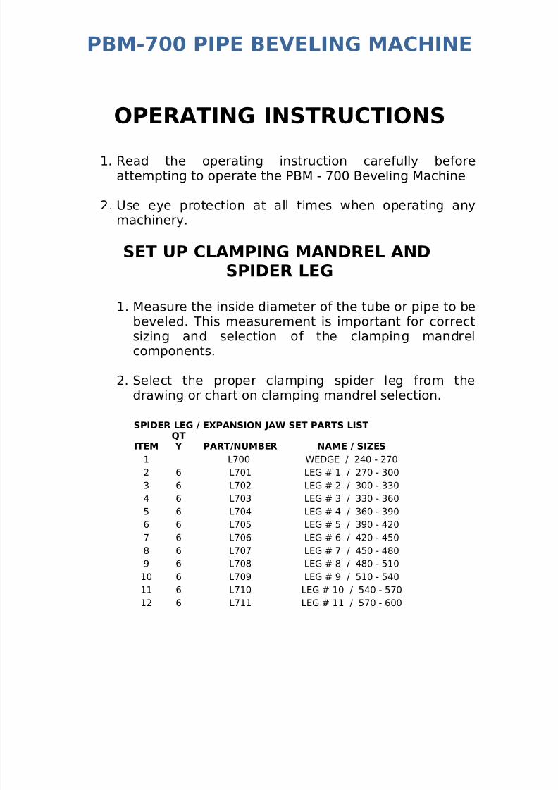
1. Measure the inside diameter of the tube or pipe to bebeveled. This measurement is important for correctsizing and selection of the clamping mandrelcomponents.
2. Select the proper clamping spider leg from thedrawing or chart on clamping mandrel selection.
SPIDER LEG / EXPANSION JAW SET PARTS LIST
ITEMQT Y PART/NUMBER NAME / SIZES
1 L700 WEDGE / 240 - 270
2 6 L701 LEG # 1 / 270 - 300
3 6 L702 LEG # 2 / 300 - 330
4 6 L703 LEG # 3 / 330 - 360
5 6 L704 LEG # 4 / 360 - 390
6 6 L705 LEG # 5 / 390 - 420
7 6 L706 LEG # 6 / 420 - 450
8 6 L707 LEG # 7 / 450 - 4809 6 L708 LEG # 8 / 480 - 510
10 6 L709 LEG # 9 / 510 - 540
11 6 L710 LEG # 10 / 540 - 570
12 6 L711 LEG # 11 / 570 - 600

7/28/2019 Operating and Maintenance Manual Pbm 700
http://slidepdf.com/reader/full/operating-and-maintenance-manual-pbm-700 10/19
PBM-700 PIPE BEVELING MACHINE
3. Install the correct spider legs on the ID clampingmandrel, being sure all spider legs are tightened andseated properly.
SET UP PBM-700 BEVELING MACHINE FORUSE
Before putting in the mandrel into beveling machine, make sure youhave loosen the torque acceptance key adjustment screws (item 38)on the beveling machine. So the mandrel will be able to align with 2slots on the mandrel shaft.
Clean and gently insert the clamping mandrel assembly into the pipeend, while keeping the Flange Facer oriented 180 degrees from the
hydraulic motor to balance the machine. Check to make sure thespider legs are not on inside weld seam. When on weld seam will causemisalignment.
Gently tight the draw nut till the mandrel expands and touches theinner wall of the pipe. Once it touches the inner wall the machineshould be jiggled before tightened thoroughly to ensure that themachine sits in the proper center.
NOTE:With the mandrel loose enough for the mandrel to slide along theinside of the tube/pipe, move the cutting head about 1” away from the

7/28/2019 Operating and Maintenance Manual Pbm 700
http://slidepdf.com/reader/full/operating-and-maintenance-manual-pbm-700 11/19
PBM-700 PIPE BEVELING MACHINE
end of the tube/pipe, and tighten the draw rod nut while gentlyworking the tool back and forth so that the clamping blades seatevenly. It is very important to make sure the spider legs are not on theinside of the weld bead, this will cause misalignment of head.

7/28/2019 Operating and Maintenance Manual Pbm 700
http://slidepdf.com/reader/full/operating-and-maintenance-manual-pbm-700 12/19
PBM-700 PIPE BEVELING MACHINE
SELETING AND SETTING CUTTING INSERTSWARNING! Use of dull or improperly designed Tool Bits or Tool Bitsnot manufactured by TECHNO NEXUS may result in poor performanceand may constitute abuse of this machine and therefore voids the TECHNO NEXUS factory warranty.
1. Select the correct combination of cutting tools and slip theminto the cutter head.
Be sure to place the cutting blades in a position where the blades will
but the entire area required. Make sure that when putting in the toolblades, the cutting edge is facing way from the set-screw. Althoughonly one bevel blade is required for cutting.

7/28/2019 Operating and Maintenance Manual Pbm 700
http://slidepdf.com/reader/full/operating-and-maintenance-manual-pbm-700 13/19
7/28/2019 Operating and Maintenance Manual Pbm 700
http://slidepdf.com/reader/full/operating-and-maintenance-manual-pbm-700 14/19
PBM-700 PIPE BEVELING MACHINE
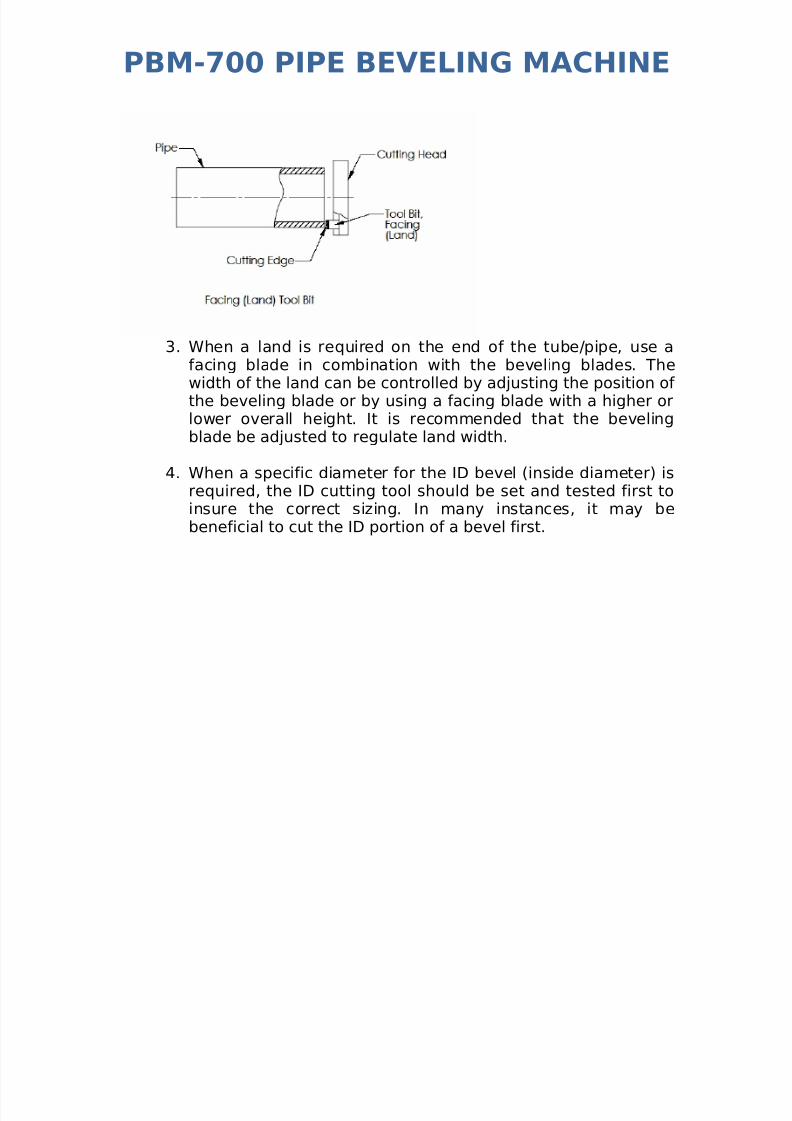
3. When a land is required on the end of the tube/pipe, use afacing blade in combination with the beveling blades. Thewidth of the land can be controlled by adjusting the position of the beveling blade or by using a facing blade with a higher orlower overall height. It is recommended that the bevelingblade be adjusted to regulate land width.
4. When a specific diameter for the ID bevel (inside diameter) isrequired, the ID cutting tool should be set and tested first toinsure the correct sizing. In many instances, it may bebeneficial to cut the ID portion of a bevel first.
7/28/2019 Operating and Maintenance Manual Pbm 700
http://slidepdf.com/reader/full/operating-and-maintenance-manual-pbm-700 15/19
PBM-700 PIPE BEVELING MACHINE
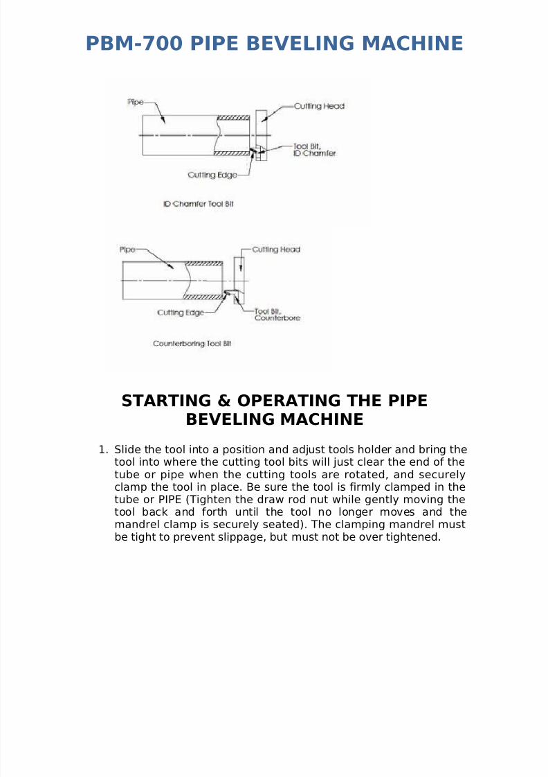
STARTING & OPERATING THE PIPEBEVELING MACHINE
1. Slide the tool into a position and adjust tools holder and bring thetool into where the cutting tool bits will just clear the end of thetube or pipe when the cutting tools are rotated, and securelyclamp the tool in place. Be sure the tool is firmly clamped in thetube or PIPE (Tighten the draw rod nut while gently moving thetool back and forth until the tool no longer moves and themandrel clamp is securely seated). The clamping mandrel mustbe tight to prevent slippage, but must not be over tightened.
7/28/2019 Operating and Maintenance Manual Pbm 700
http://slidepdf.com/reader/full/operating-and-maintenance-manual-pbm-700 16/19
PBM-700 PIPE BEVELING MACHINE
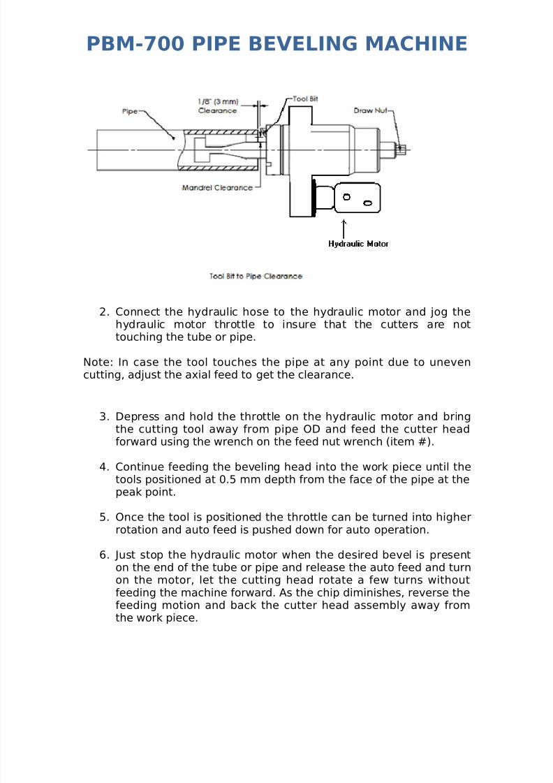
2. Connect the hydraulic hose to the hydraulic motor and jog thehydraulic motor throttle to insure that the cutters are nottouching the tube or pipe.
Note: In case the tool touches the pipe at any point due to unevencutting, adjust the axial feed to get the clearance.
3. Depress and hold the throttle on the hydraulic motor and bringthe cutting tool away from pipe OD and feed the cutter headforward using the wrench on the feed nut wrench (item #).
4. Continue feeding the beveling head into the work piece until thetools positioned at 0.5 mm depth from the face of the pipe at thepeak point.
5. Once the tool is positioned the throttle can be turned into higherrotation and auto feed is pushed down for auto operation.
6. Just stop the hydraulic motor when the desired bevel is presenton the end of the tube or pipe and release the auto feed and turnon the motor, let the cutting head rotate a few turns withoutfeeding the machine forward. As the chip diminishes, reverse thefeeding motion and back the cutter head assembly away fromthe work piece.

7/28/2019 Operating and Maintenance Manual Pbm 700
http://slidepdf.com/reader/full/operating-and-maintenance-manual-pbm-700 17/19
PBM-700 PIPE BEVELING MACHINE
7. Release the throttle on the hydraulic motor assembly anddisconnect the hydraulic supply hose. Back off the feedmechanism until the threads on the mandrel shaft assembly areeven with the end of the feed nut. Loosen the draw rod nut and
gently rock the tool to loosen the clamping mandrel and removethe beveling machine from the work piece.
PBM-700 PIPE BEVELING MACHINE
SPECIFICATIONS1) Model PBM-700 Beveling machine with Hydraulic Motor2) Weight: 40 Kgs WITHOUT Power Pack
3) Power requirements: 10 Amps 415 V 3 Ph 50 Hz4) Basic Pipe sizes: ID 250 mm to OD 700 mm5) Wall thickness to 80 mm6) Counter boring operations: YES7) Material cutting capabilities: Mild Steels, chrome steels(35 Rc. Max), Stainless Steel, Copper-Nickel, Inconel, andAluminum without limitations except size and wall thicknessas specified above.
TOOL BITSSTANDARD TOOL BITS FOR PBM - 700BEVELING MACHINEPart #PB-BT 00 Boring BITPB-BT 12 Boring BITPB-BT 15 Boring BITPB-FT 00 FACING BITPB-BT 45 Deg Bevel BIT
PB-BT 37 1/2 Deg Bevel BIT
7/28/2019 Operating and Maintenance Manual Pbm 700
http://slidepdf.com/reader/full/operating-and-maintenance-manual-pbm-700 18/19
PBM-700 PIPE BEVELING MACHINE
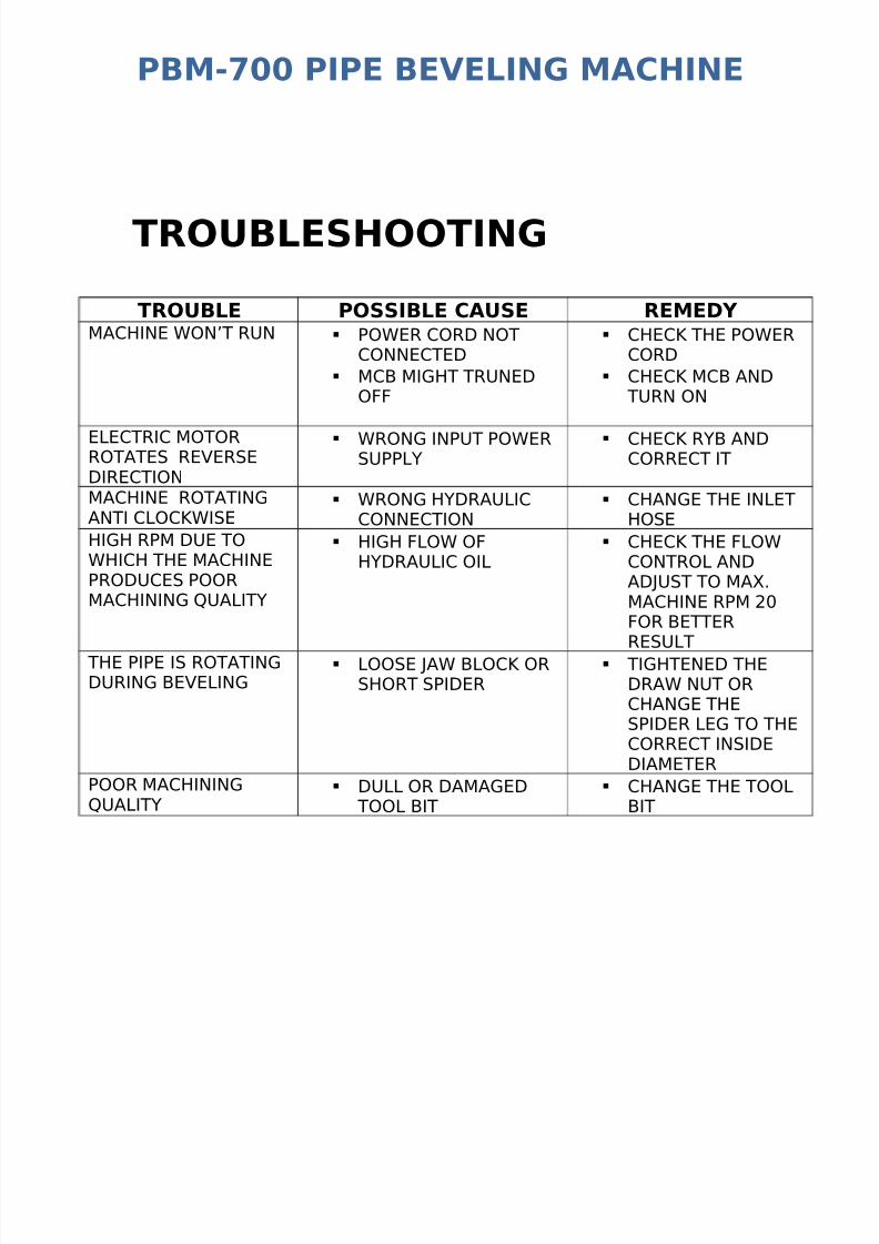
TROUBLESHOOTING
TROUBLE POSSIBLE CAUSE REMEDY MACHINE WON’T RUN POWER CORD NOT
CONNECTED
MCB MIGHT TRUNEDOFF
CHECK THE POWERCORD
CHECK MCB AND TURN ON
ELECTRIC MOTORROTATES REVERSEDIRECTION
WRONG INPUT POWERSUPPLY
CHECK RYB ANDCORRECT IT
MACHINE ROTATINGANTI CLOCKWISE
WRONG HYDRAULICCONNECTION
CHANGE THE INLETHOSE
HIGH RPM DUE TOWHICH THE MACHINEPRODUCES POORMACHINING QUALITY
HIGH FLOW OFHYDRAULIC OIL
CHECK THE FLOWCONTROL ANDADJUST TO MAX.MACHINE RPM 20FOR BETTERRESULT
THE PIPE IS ROTATINGDURING BEVELING
LOOSE JAW BLOCK ORSHORT SPIDER
TIGHTENED THEDRAW NUT ORCHANGE THESPIDER LEG TO THECORRECT INSIDEDIAMETER
POOR MACHININGQUALITY
DULL OR DAMAGED TOOL BIT
CHANGE THE TOOLBIT

7/28/2019 Operating and Maintenance Manual Pbm 700
http://slidepdf.com/reader/full/operating-and-maintenance-manual-pbm-700 19/19