operating and maintenance manual for type s flowmeters · operating and maintenance manual for type...
TRANSCRIPT

Operating and MaintenanceManual for Type S Flowmeters
M115Rev. AType S Flowmeters:11⁄2″ & 2″ with 800 Series Registers
®

TABLE OF CONTENTS
Installation .................................................................................................... 1
Operation ..................................................................................................... 3
Printer Models .............................................................................................. 3
Calibration .................................................................................................... 4
Maintenance................................................................................................. 5
Register ............................................................................................... 5
Preset Valve ........................................................................................ 7
Measuring Chamber .......................................................................... 11
Stuffing Box ....................................................................................... 15
General Maintenance ................................................................................. 16
TroubleShooting Guide .............................................................................. 18
Dimensions ................................................................................................ 20

1 1/2″″″″″ & 2″″″″″ TYPE “S” FLOWMETERS WITH 800 SERIESREGISTERS AND 2″″″″″ PRESET VALVE
The Preset Valve is provided either with a Double Trip Mechanism, or a Single TripMechanism, depending upon the flow rate and viscosity of the liquid to be metered.
The Double Trip Valve may be used for liquids having viscosities less than 10,000S.S.U. (i.e., water, gasoline, etc.). Use of the Double Trip Valve will be determined bythe need to reduce shock pressure in the line, which may result either from highoperating pressure or high rates of flow. A fine mesh strainer should be used to protectthe Preset Valve piston and cylinder as well as to protect the measuring element in theflowmeter.
Single Trip Valves may be used for viscosities greater than 10,000 S.S.U., or whenliquids, such as water, solvents, gasoline, etc., are operated at low rates of flow ingravity type installations.
If not certain of the suitability of the valve to the characteristics of the liquid, contactyour nearest authorized Actaris Neptune distributor. A good rule of thumb, use double-trip valves if flow rate is greater than 50 gallons a minute and the viscosity is less than10,000 S.S.U.
INSTALLATION
Instructions for installation and testing of Actaris Neptune Type S Flowmeters arecontained in this manual. Should more detailed information and further assistance benecessary, do not hesitate to contact the representative from whom you purchasedthe flowmeter, or Actaris Neptune.
StrainerPlan the installation in such a way as to allow the strainer to be coupled directly to
the inlet of the flowmeter. Where this is not possible, any piping between these unitsshould be thoroughly cleaned out.
Be careful to allow room for easy removal of the strainer basket.
Air/Air ReleaseAir releases are not supplied for all liquids, but when an air release valve is used,
it should be installed in a position as close as possible to the inlet of the flowmeter. Thiswill ensure the removal of the greatest possible amount of air from the liquid beforemetering.
PipingUse pipe cement on male threads only.
The piping on the outlet side of the flowmeter should rise above the height of theflowmeter in order to form a natural trap. This arrangement is necessary to eliminatethe possibility of draining the measuring chamber. Where this is not possible, an anti-drain valve may be used.
Experience has shown the need for a valved bypass connection to be installedaround the flowmeter. This arrangement permits product flow in the event that theflowmeter must be removed for repair.
1 1/2″″″″″ & 2″″″″″ TYPE “S”FLOWMETER WITH 800SERIES REGISTERS AND2″″″″″ PRESET VALVE
INSTALLATION
Before Installing TheFlowmeter
Piping
Page 1

Where an air release valve is used, the vent pipe should be 3/4” inside diameterpipe or tubing. Care should be taken to prevent any possible obstruction to the freeflow of air in this line. This line should be connected to a drip collecting drum or backto storage. Do not vent to atmosphere.
The connecting piping should be firmly secured to prevent strain on the flowmetercasing. Provide for expansion or contraction of long runs of piping due to temperaturechanges, with self aligning couplings, or expansion joints.
All piping on the inlet side of the flowmeter should be thoroughly cleaned out.Whenever possible, place a spool in the place of the flowmeter and flush out alllines thoroughly before the flowmeter is installed. The majority of service callson new installations are eliminated by following these directions.
Inlet and outlet are clearly marked; do not install backwards.
The connection to the outlet of the valve must be removable (or sufficiently flexible)to permit 2″ axial movement in order for the valve to be removed from the flowmeterfor servicing.
To change the direction in which the register will face with respect to the pipe. (Seepage 6).
Open line valves slowly, allowing liquid to gradually enter flowmeter. (Use care notto overspeed the flowmeter).
Pass sufficient liquid to clear the lines of air. Check the rate of flow. It should notexceed the rated capacity of the flowmeter.
Set the bypass of the pump so that the maximum pressure at no time exceeds 125psi. When the installation is completed, check that the shock pressure (the pressureas the shut-off or Preset Valve is closed) at the flowmeter does not exceed 125 psi.The pressure may be checked by installing a pressure gauge at the inlet of theflowmeter. Do not try to increase the flow through undersize pipes and fittings bymeans of excessive pressures, as this will result in leaking gaskets and collapsed airrelease floats when air release equipment is used.
Temperature of the liquid should not exceed that specified for the flowmeter.
Test the flowmeter as per instructions on page 4. All flowmeters are carefullycalibrated and tested at the factory, and no adjustment should be necessary.Instructions for correcting the calibration, if the registration appears to be inaccurate,are contained on page 4.
When the installation is still new, the strainer should be cleaned very frequently.After the system has had a chance to be thoroughly washed out, only periodic cleaningis necessary.
Air Vent Line
When Installing Flowmeter
After Installing
Cleaning The Strainer
Page 2

OPERATION1. Reset the register to zero by turning reset knob to the rear stop. On Printer models,
first insert ticket. (See below).
2. Set the Preset wheels to the desired quantity.
3. Start pump - Open Preset Valve and make delivery.
4. After completing delivery on Printer models, stamp final reading on ticket by turningoperating knob to the front stop and remove ticket.
Pushing the red emergency stop button will trip the valve. After it has been usedeither the delivery may be completed automatically as originally set by re-opening thevalve or the mechanism may be set for a new figure. The accuracy of delivery in eithercase is not affected.
Page 3
PRINTER MODELSTo insert a ticket be sure that the oper-
ating knob is turned to its forward stop.Then depress the Dust Bar and insert theticket in the ticket slot under it “face-down,bottom end first” as noted on the instruc-tion plate. Turn the operating knob to itsrear stop. This resets the visible wheels tozero, locks the ticket in place, and printsthe initial reading on the ticket.
It is now impossible to remove theticket without tearing it.
Upon completion of delivery, turn theoperating knob to its forward stop. Thisoperation prints the final reading and re-leases the ticket.
OPERATION
To Operate The Flowmeter
Emergency Stop
PRINTER MODELS
To Insert And Remove Tickets
The Printer Registers are shipped fromthe factory with the ticket guides properlyadjusted. If for any reason it is necessaryto reposition the ticket, proceed as fol-lows:
1. Remove top cover of register.
2. Insert a ticket into the printer. Loosenthe clamp screws on the rear of theticket guides. Move the guides to theright or left as required. Tighten clampscrews. The ticket must slide freelybetween the guides. If the ticket bindsat the forward end of the guide, removethe guide and rebend the tail.
To Adjust Ticket Guides
DUST BAR
CLAMPSCREW
RESET KNOB
PRESET BUTTONSTRIP ADJUSTINGSCREW COVER
EMERGENCYSTOP BUTTON
STOP PINS
TICKET GUIDE LETTER WHEELS
FIGURE 2PRINT UNIT ADJUSTMENTS
FIGURE 1PRESET 800 SERIES PRINTER
REGISTER
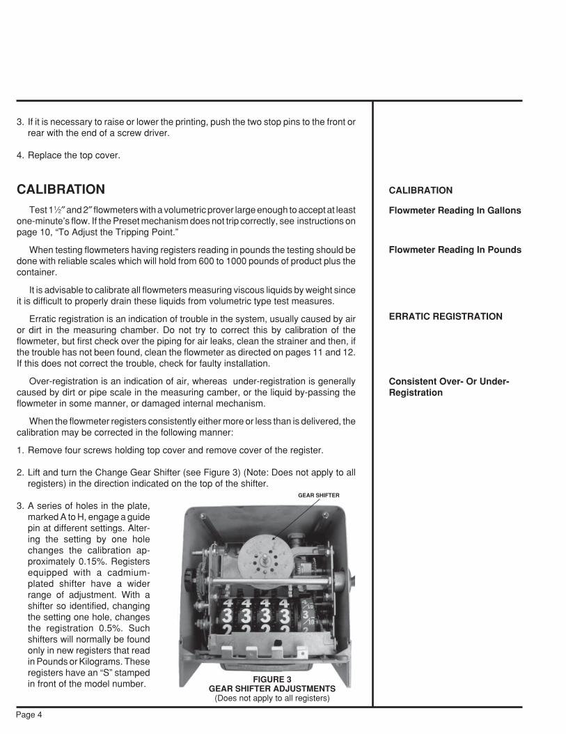
FIGURE 3GEAR SHIFTER ADJUSTMENTS
(Does not apply to all registers)
Page 4
3. If it is necessary to raise or lower the printing, push the two stop pins to the front orrear with the end of a screw driver.
4. Replace the top cover.
CALIBRATIONTest 11⁄2″ and 2″ flowmeters with a volumetric prover large enough to accept at least
one-minute’s flow. If the Preset mechanism does not trip correctly, see instructions onpage 10, “To Adjust the Tripping Point.”
When testing flowmeters having registers reading in pounds the testing should bedone with reliable scales which will hold from 600 to 1000 pounds of product plus thecontainer.
It is advisable to calibrate all flowmeters measuring viscous liquids by weight sinceit is difficult to properly drain these liquids from volumetric type test measures.
Erratic registration is an indication of trouble in the system, usually caused by airor dirt in the measuring chamber. Do not try to correct this by calibration of theflowmeter, but first check over the piping for air leaks, clean the strainer and then, ifthe trouble has not been found, clean the flowmeter as directed on pages 11 and 12.If this does not correct the trouble, check for faulty installation.
Over-registration is an indication of air, whereas under-registration is generallycaused by dirt or pipe scale in the measuring camber, or the liquid by-passing theflowmeter in some manner, or damaged internal mechanism.
When the flowmeter registers consistently either more or less than is delivered, thecalibration may be corrected in the following manner:
1. Remove four screws holding top cover and remove cover of the register.
2. Lift and turn the Change Gear Shifter (see Figure 3) (Note: Does not apply to allregisters) in the direction indicated on the top of the shifter.
3. A series of holes in the plate,marked A to H, engage a guidepin at different settings. Alter-ing the setting by one holechanges the calibration ap-proximately 0.15%. Registersequipped with a cadmium-plated shifter have a widerrange of adjustment. With ashifter so identified, changingthe setting one hole, changesthe registration 0.5%. Suchshifters will normally be foundonly in new registers that readin Pounds or Kilograms. Theseregisters have an “S” stampedin front of the model number.
CALIBRATION
Flowmeter Reading In Gallons
Flowmeter Reading In Pounds
ERRATIC REGISTRATION
Consistent Over- Or Under-Registration
GEAR SHIFTER

Page 5
When a register equipped with the plated shifter replaces one that is not plated, thechange gears must be adjusted downward by approximately 31⁄2%. For this reason,replace existing change gears with new gears in accordance with Form TSG-310.
After changing the calibration always replace top cover; making sure that the sheetsteel housing on the sides and back fits into the groove in the bottom edge of cover.Run a small amount of liquid through the flowmeter before testing. This operation mustbe performed to ensure that all backlash in the gearing has been removed. When thishas been done, retest the flowmeter as outlined in section entitled “Calibration.” Inorder to prevent tampering, always reseal the register after calibration is completed.
Note: For broader change gear requirements and calibration adjustment refer toForm TSG-310.
MAINTENANCEREGISTER
Only minor field repair of register parts is recommended. When a register is in needof repair of service other than that for which instruction is given here, it should bereturned to the nearest authorized Actaris Neptune distributor.
Disconnect valve linkage at valveend. (Cotter pin, washer, and clevispin must be removed before hand.)Loosen the two clamp screws onlower front of the register. Lift regis-ter off flowmeter.
When one register is removedand another substituted, (1) Checkthe number of teeth on the ChangeGears (see Figure 4). They must bethe same as the gears on the oldregister and on the same respec-tive spindles. The number of teethis stamped on each gear. To removethese gears, close the split end of thespindle with a pair of pliers and pulloff the gear. After putting on a gear,spread the end of the spindle slightly.(2) Make sure that the position of theChange Gear Shifter is the same onthe new register as the old one. Eachhole is lettered for convenience.
Note: Type S meters supplied since 1990 do not utilize the gear shiftermechanism.
Register mask are made of plastic and require special treatment. Instructions forcleaning are given below:
If the mask becomes soiled with grease and oil, solvents for these substances,such as kerosene or naphtha, may be used to remove dirt. However, sprays that arecommonly employed in cleaning glass windshields must not be used as cleaners,since they may contain solvents for the mask.
MAINTENANCE
REGISTER
Repair of Register
To Remove Register FromFlowmeter
To Clean Register Mask
FIGURE 4CHANGE GEAR ARRANGEMENT
“REV.” SPINDLEFOR CHANGE GEAR “S”
CHANGE GEAR “R”CHANGE GEAR “S”(ON STD. SPINDLE)
A water solution of nonabrasive soap is recommended for washing grease, oil, ordirt from the mask. It is then cleansed by rubbing gently with a soft cloth, in a mannersimilar to cleaning window glass, rinsing the mask in clean water, and finally drying.
Scouring cleanser and similar material must not be used in cleaning the mask,since they contain abrasives that scratch the surface.
The use of solvents, such as acetone, ethyl acetate, benzene, and ethylenedichloride, to brighten the surface of the mask is never recommended since thesesubstances soften the surface of the plastic.
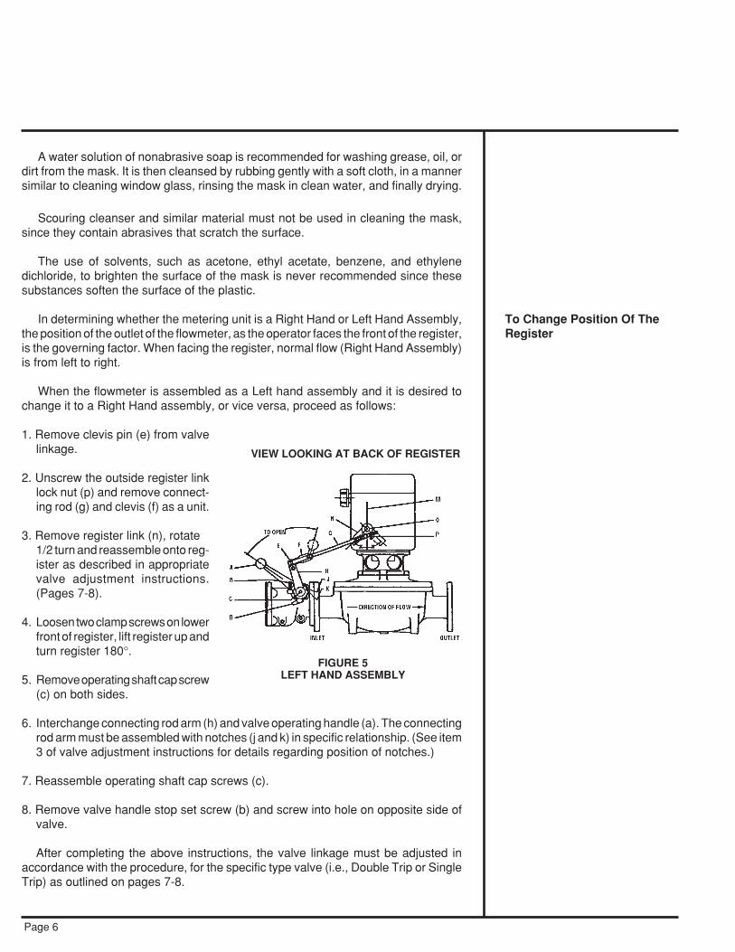
In determining whether the metering unit is a Right Hand or Left Hand Assembly,the position of the outlet of the flowmeter, as the operator faces the front of the register,is the governing factor. When facing the register, normal flow (Right Hand Assembly)is from left to right.
When the flowmeter is assembled as a Left hand assembly and it is desired tochange it to a Right Hand assembly, or vice versa, proceed as follows:
1. Remove clevis pin (e) from valvelinkage.
2. Unscrew the outside register linklock nut (p) and remove connect-ing rod (g) and clevis (f) as a unit.
3. Remove register link (n), rotate1/2 turn and reassemble onto reg-ister as described in appropriatevalve adjustment instructions.(Pages 7-8).
4. Loosen two clamp screws on lowerfront of register, lift register up andturn register 180°.
5. Remove operating shaft cap screw(c) on both sides.
6. Interchange connecting rod arm (h) and valve operating handle (a). The connectingrod arm must be assembled with notches (j and k) in specific relationship. (See item3 of valve adjustment instructions for details regarding position of notches.)
7. Reassemble operating shaft cap screws (c).
8. Remove valve handle stop set screw (b) and screw into hole on opposite side ofvalve.
After completing the above instructions, the valve linkage must be adjusted inaccordance with the procedure, for the specific type valve (i.e., Double Trip or SingleTrip) as outlined on pages 7-8.
Page 6
To Change Position Of TheRegister
VIEW LOOKING AT BACK OF REGISTER
FIGURE 5LEFT HAND ASSEMBLY

PRESET VALVE
Note: Before any adjustment of the Double Trip or Single Trip Preset Valve ismade, be sure that the Preset setting wheels indicate a quantity, other than zero,to insure that the trip mechanism of the register is in proper position.
To Adjust Double Trip Valve Linkage With Valve At Outlet Of Flowmeter
1. Depress the emergency stop button on the register and turn the shaft (o) clockwise.
2. Assemble register arm (n) on knurled knob in position as shown for specificassembly. (See Figure 6). Arm should move an equal distance each side of verticalcenter line (m) (Angle x=x).
3. Assemble valve arm (h) as shown for specific assembly. On the right handassembly there must be one notch between the cast mark (k) on the valve arm andthe cast mark (j) on the stop plate (j above k). On the left hand assembly these castmarks must be in line.
4. Assemble one nut (p) on connecting rod (g) and assemble clevis to the other endof the connecting rod a distance of 1”.
5. Insert end of connecting rod through register arm link and assemble clevis (f) tovalve arm (h) using upper hole (See Figure 6). Insert clevis pin (e).
6. Open valve all the way. The opening of the valve is stopped by the set screw (b)which should project approximately 1/8” below the lug holding it. Turn shaft (o)counter clockwise to latch up mechanism. With valve held open, tighten nut (p)against register arm link. Then assemble and tighten second nut at (p).
7. Depress the emergency stop button and allow the valve to close. At this point thelinkage between the valve and the register must be free. If it is not, the aboveadjustments must be rechecked.
8. Set the register to deliver the minimum quantity and open the valve to run productthrough the flowmeter.
9. After the initial trip occurs the valve should close to the intermediate flow position.This rate should be approximately 20 to 25 gpm. If the valve closes too far, unscrewclevis (f) on rod (g) to hold valve open further. If the rate of flow is too fast duringthe intermediate position, turn the clevis onto the rod to allow the valve to closefurther. It should not be necessary to turn more than one turn in either direction.
10. It is sometimes necessary to change the position of set screw (b) if the clevis hasbeen readjusted. If the register mechanism will not latch up, unscrew the set screwto allow the valve to open further. If the connecting rod (g) is under compression,when the valve is held all the way open, turn the set screw down to relieve thepressure on the register.
11. The Preset trip adjusting screw should be near its mid-position. If a smalladjustment of this screw will not permit the register to shut off “on the mark” it isusually possible to correct this by a slight adjustment of the clevis (f). This will move
Page 7
PRESET VALUE
To Adjust Double Trip ValveLinkage With Valve At OutletOf Flowmeter

the main valve nearer to or further away from its seat during the intermediate flowand thereby change the amount of time needed for the valve to fully close at thelast trip. (Also see page 11, “To Adjust the Tripping Point”).
Note: If it is difficult to obtain proper rate of flow during intermediate trip positionand still have register latch up fully, check Preset valve to insure that it is openingall the way. Check valve by removing set screw (b) and clevis (f) from valve arm;open valve as far as possible. The distance between lug on arm and lug on stopplate must not be more than 1⁄4”.
Note: Normal (Standard) left and right hand configurations.
To Adjust Double Trip Valve Linkage With Valve At Inlet of Flowmeter(See Note, Page 7)
1. Depress the emergency stop button on the register and turn the shaft (o) clockwise.
2. Assemble register arm (n) on knurled knob in position as shown for specificassembly. (See Figure 7). Arm should move an equal distance each side of verticalcenter line (m) (Angle x=x).
3. Assemble valve arm (h) as shown for specific assembly. On the left hand assemblythere must be one notch between the cast mark (k) on the valve arm and the castmark (j) on the stop plate (k above j). On the right hand assembly these cast marksmust be in line.
4. Assemble one nut (p) on connecting rod (g) and assemble clevis to the other endof the connecting rod a distance of 1”.
5. Insert end of connecting rod through register arm link and assemble clevis (f) tovalve arm (h) using upper hole. (See Figure 7). Insert clevis pin (e).
6. Open valve all the way. The opening of the valve is stopped by the set screw (b)which should project approximately 1/8” below the lug holding it. Turn shaft (o)counter clockwise to latch up mechanism. With valve held open, tighten nut (p)against register arm link. Then assemble and tighten second nut at (p).
LEFT-HAND ASSEMBLY RIGHT-HAND ASSEMBLY
To Adjust Double Trip ValveLinkage With Valve At Inlet ofFlowmeter
Page 8
VIEW LOOKING AT BACK OF REGISTER
FIGURE 6

7. Depress the emergency stop button and allow the valve to close. At this point thelinkage between the valve and the register must be free. If it is not, the aboveadjustments must be rechecked.
8. Set the register to deliver the minimum quantity and open the valve to run productthrough the flowmeter.
9. After the initial trip occurs the valve should close to the intermediate flow position.This rate should be approximately 20 to 25 gpm. If the valve closes too far, turnthe clevis (f) onto rod (g) to hold valve open further. If the rate flow is too fast duringthe intermediate position, unscrew clevis (f) on rod (g) to allow the valve to closefurther. It should not be necessary to turn clevis more than one turn in eitherdirection.
10. It is sometimes necessary to change the position of set screw (b) if the clevis hasbeen readjusted. If the register mechanism will not latch up, unscrew the set screwto allow the valve to open further. If the connecting rod (g) is under compression,when the valve is held all the way open, turn the set screw down to relieve thepressure on the register.
11. The Preset trip adjusting screw should be near its mid-position. If a smalladjustment of this screw will not permit the register to shut off “on the mark” it isusually possible to correct this by a slight adjustment of the clevis (f). This willmove the main valve nearer to or further away from its seat during the intermediateflow and thereby change the amount of time needed for the valve to fully close atthe last trip. (Also see page 11, “To Adjust the Tripping Point”).
Note: If it is difficult to obtain proper rate of flow during intermediate trip positionand still have register latch up fully, check Preset valve to insure that it is openingall the way. Check valve by removing set screw (b) and clevis (f) from valve arm;open valve as far as possible. The distance between lug on arm and lug on stopplate must not be more than 1⁄4″.
To Adjust Single Trip ValveLinkage
Page 9
RIGHT-HAND ASSEMBLYWITH VALVE MOUNTED AT INLET
LEFT-HAND ASSEMBLYWITH VALVE MOUNTED AT OUTLET
VIEW LOOKING AT BACK OF REGISTER
FIGURE 7

To Adjust Single Trip ValveLinkage
Page 10
To Adjust Single Trip Valve Linkage(See note, Page 7)
1. Depress the emergency stop button on the register and turn the shaft (o) clockwise.
2. Assemble register arm (n) on knurled knob in position as shown for specificassembly. (See Figure 8). Arm should move an equal distance each side of verticalcenter line (m) (Angle x=x).
3. Assemble valve arm (h) as shown for specific assembly. On the right handassembly there must be two notches between the cast mark (k) on the valve armand the cast mark (j) on the stop plate (j above k). On the left hand assembly theremust be one notch between marks (j above k).
4. Assemble one nut (p) on connecting rod (g) and assemble clevis to the other endof the connecting rod a distance of 1″.
5. Insert end of connecting rod through register arm link and assemble clevis (f) tovalve arm (h) using lower hole (y). Insert clevis pin (e).
6. Open valve all the way. The opening of the valve is stopped by the set screw (b)which should project approximately 1⁄8″ below the lug holding it. Turn shaft (o)counter clockwise to latch up mechanism. With valve held open, tighten nut (p)against register arm link. Then assemble and tighten second nut at (p).
7. Depress the emergency stop button and allow the valve to close. At this point thelinkage between the valve and the register must be free. If it is not, the aboveadjustments must be rechecked.
VIEW LOOKING AT BACK OF REGISTER
LEFT-HAND ASSEMBLYRIGHT-HAND ASSEMBLY
Note: Non-standard left hand configuration.
FIGURE 8

Page 11
To Adjust The Tripping PointTo Adjust The Tripping Point
The flowmeter is shipped from the factory with the Preset mechanism adjusted totrip correctly at maximum rates of flow while measuring water, or other test liquid atthe factory. in the instance when the Preset does not trip at zero due to differences inliquids, rate of flow, or any other reasons, an adjustment can be made. In most cases,only a minor adjustment at the register is necessary.
The adjustment at the register is identical forboth single and double trip valves. Remove thescrew located in the lower right hand corner ofthe front register housing. Insert a screw driverinto this hole and engage the slotted head of thetrip adjusting screw. One turn of this screw willchange the trip point about one-quarter of onegraduation of the first wheel.
If the Preset trips before reaching the zeromark, turn the adjusting screw in a clockwisedirection. If the Preset trips after the zero mark,turn in a counter-clockwise direction.
In some instances on Double Trip Valves anadjustment of the valve linkage may be requiredin order to have the Preset trip at the correctpoint. (See pages 8 and 9).
MEASURING CHAMBERTo Remove and Disassemble
This operation is not difficult and may be performed by any competent mechanic.No special tools are required. No trouble need be expected if these few simple, butimportant directions are followed. Do not open the flowmeter until you have checkedover all other possible causes of erratic registration.
1. Prepare a clean surface on which to place the parts as they are removed. The parts,though sturdy, are machined to close tolerance and should be handled with care.Have a replacement gasket ready before opening the flowmeter.
2. Remove the register. (See page 5).
3. Remove gear train.
4. Remove the flowmeter cover. (Will require new gasket).
5. Remove the measuring chamber form the flowmeter casing. If the chamber sticks,it may be necessary to tap maincase to free it—insert maincase bolts in holes andhit head of bolts while pulling upward on chamber. Remove thrust roller insert plate.
6. Remove three chamber assembly screws.
MEASURING CHAMBERTo Remove and Disassemble
DUST BAR
CLAMPSCREW
RESET KNOB
PRESET BUTTONSTRIP ADJUSTINGSCREW COVER
EMERGENCYSTOP BUTTON
FIGURE 9PRESET 800 SERIESPRINTER REGISTER
7. Remove the upper half of the chamber. Be careful not to scratch or nick any partof the chamber.
8. Lift out the disc piston by its spindle.
9. The chamber is now completely disassembled. The parts may be most easilycleaned of scale, etc., by means of a good, coarse, stiff bristle (not wire) brush andgasoline or suitable cleaning agent. All foreign matter may be removed in thismanner. Do not use abrasives, such as emery cloth or sand paper.
To Reassemble Chamber In The Flowmeter
1. Clean the joints where the two chamber halves fit together.
2. Check that the thrust roller rotates freely in the disc piston.
3. Assemble the disc piston into the lower chamber half, aligning the slot in the formerwith the diaphragm in the chamber half. The disc piston cannot be dropped into thechamber vertically but must be assembled at a slight angle.
4. Assemble the upper chamber half to the lower. The diaphragm must fit into its slotin the upper half. The upper and lower halves should then snap together. Replacethree screws to hold the chamber together.
5. Insert the thrust roller bearing plate. The thrust roller must not be in the path of theplate or either part may become damaged. Never use a hammer to insert the plate.
6. Operate the disc piston slowly, it should move freely without any “catch”. If it doesnot, check that the upper and lower chamber halves are fitted tightly together. if theyare, then the fault lies within the chamber and it must be disassembled to check forforeign matter or burrs.
7. Clean out the casing.
8. Lift the chamber by the piston spindle and drop it into position in the main casing.The top of the chamber should be level with the gasket seat. If it is not, pressing byhand should make it so.
Page 12
To Reassemble ChamberFlowmeter
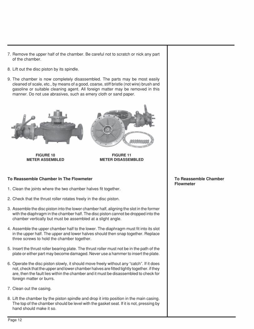
FIGURE 10METER ASSEMBLED
FIGURE 11METER DISASSEMBLED

Page 13
9. When replacing the cover,first inspect the gasket andthen set the arm of the geartrain so that it will not comedown on the piston spindle.
10. Make sure that the cover isdown on its seat before tight-ening the bolts.
11. After assembly is complete,open line valve slowly allow-ing liquid to gradually enterflowmeter. (Use care not tooverspeed the flowmeter).
To Disassemble And AssembleDouble Trip Valve
1. Remove valve from flowmeter.
2. Remove two screws holding retaining ring at inlet of valve.(Caution: End plate should be held by hand when removing screws because ofspring tension beneath the plate).
All internal parts of the valve can now be removed, with the exception of theoperating shaft mechanism. The removal of the internal parts from the valve bodymay be assisted by operating the valve handle as when opening the valve.
3. Disassemble piston and throttling ring assembly. Inspect valve seats, “O” ringgasket, piston ring, and cylinder for damaged surfaces. Replace all defective partswith new parts.
4. Reassemble piston and throttling ring assembly. Apply shellac under heads ofthree piston assembly screws.
5. Assemble pilot valve on pilot valve rod. Place assembly into valve body.
6. Place one end of spring over pilot valve boss.
7. Place other end of spring over boss in cylinder and press cylinder down over piston.Back of cylinder should be below flange face for proper assembly.
8. Hold cylinder in place, place “O” ring in body recess and attach retaining ring withtwo screws.
9. Open valve as far as possible—make sure that valve is not being stopped by setscrew.
FIGURE 12MEASURING CHAMBER PARTS
*These parts are shown for identification purposes only. Not sold as separateunits.
To Disassemble And AssembleDouble Trip Valve
Chamber UpperHalf*
Thrust Roller InsertPlate on Channel
Disk Piston
Chamber LowerHalf*
Thrust RollerScrews

To Adjust Rate Of Closing Of Type 1A Double Trip Preset Valve From its FullOpen Position To The Intermediate Position
Variations in the viscosity of the liquids being measured will cause changes in therate of closing of the valve from its full open position to its intermediate position (Valveshould reach its intermediate position with approximately 4 gallons remaining onPreset setting wheels).
Setting of Orifice Plate is indicated on tag attached to valve.The rate of closing can be adjusted by changing the position of Orifice Plate which
is readily accessible through inlet of valve. (Valve does not have to be disassembled).Position of Orifice Plate can be changed by removing Screw and Lock Washer and
turning plate.
1. The normal position of Orifice Plate in valve to be used with water or other lowviscosity liquids will be set with Orifice opening covered. If valve closes too slowlywith this setting, turn plate counter clockwise to expose either small, medium orlarge hole as required.
2. The normal position of Orifice Plate in valve to be used with sugar syrups or otherhigh viscosity liquids will be set with large hole over Orifice opening. If valve closestoo quickly with this setting turn plate clockwise to expose either of the two smallholes or covering the orifice, as required.
To Disassemble And Assemble Single Trip Valve
1. Remove valve from flowmeter.
2. Remove two screws holding retaining ring at inlet valve.
(Caution: End plate should be held by hand when removing screws because ofspring tension beneath the plate).
Page 14
To Adjust Rate Of Closing OfType 1A Double Trip PresetValve From Its Full Open Po-sition To The IntermediatePosition
View of valveinlet showingposition ofOrifice Platefor water andother lowviscosityliquids. Notethat Orificeopening iscompletelycovered.
View of valveinlet showingposition ofOrifice Plate forsugar syrupsand other highviscosityliquids. Notethat large holeis positionedover opening.
To Disassemble And AssembleSingle Trip Valve
ScrewHoles
(4)
OrificePlateHoles
(3) OrificePlateHoles
(3)
ScrewHoles
(4)
Orifice OpeningCovered by Plate
Orifice Opening
FIGURE 13ORIFICE PLATE

All internal parts of the valve can now be removed with the exception of theoperating shaft mechanism. The removal of the internal parts from the valve bodymay be assisted by operating the valve handle as when opening the valve.
3. Disassemble valve disc assembly. Inspect valve disc and “O” ring gasket fordamaged surfaces and replace all defective parts.
4. Reassemble disc assembly. Apply shellac under heads of three screws.
5. Install disc assembly into valve body.
6. Place one end of spring over boss on disc assembly.
7. Place other end of spring over boss in spring retaining ring and attach to valve bodywith two screws.
To Inspect Operating Shaft Seals of Auto-Stop Valves
The following steps should be followed for both Double and Single Trip Valves ifit becomes necessary to disassemble the operating shafts because of leakage ormechanical failure. A leaking shaft seal cannot be corrected by excessive tighteningof the bearing bracket screws. In this case new shaft seals are usually required. (Seeparts list P401).
1. Remove valve handle connecting rod arm, two stop plates and two rollpins.Remove eight screws and pry off two shaft bearing brackets. Do not damage gaskets.
2. The two shaft seals can be inspected for damaged surfaces. Replace any defectiveseals.
3. To remove the operating shaft and two shaft bearings, first remove the two screwsin the valve operating cam. Inspect the shaft for score marks and replace ifnecessary. New seals are worthless if used with a badly scored shaft.
4. Reassemble the operating shaft and cam.
5. Replace two shaft bearings, two seals, two bearing brackets and flat gaskets, tworollpins, two stop plates, connecting rod arm and valve handle.
STUFFING BOX
Leakage At The Stuffing BoxLeakage just below the register or below the gear train adapter on exterior gear
train flowmeters, is the sign of a leaking stuffing box.
Loose Or Worn Stuffing Box Nut
Remove the register. (See page 5). If tightening the stuffing box nut by the fingersdoes not stop this leak, replace with a newly packed nut or u-cup. It may also benecessary to replace the spindle. These nuts are carefully packed and the hole
Page 15
To Inspect Operating Seals ofAuto-Stop Valve
STUFFING BOX
Leakage At The Stuffing Box
Loose Or Worn Stuffing BoxNut

machine-reamed to the size of the spindle at the factory. Do not try to repack becausehand packed nuts cause excessive friction and scoring of the spindle.To Replace The Gear Train
1. Remove the register and regis-ter adapter on internal gear trainmodels. On external gear trainmodels, the gear train is inte-gral to the adapter; replacingthe adapter replaces the geartrain.
2. Remove star or fork connec-tion on flowmeter stuffing boxspindle using a No. 8 AllenWrench.
3. For internal gear train modelsremove the flowmeter coverwith gear train assembly at-tached. Keep dirt out of theflowmeter and avoid damageto the cover gasket.
4. Unscrew the stuffing box nut(1).
5. Remove the clamp nut (2); geartrain assembly can be removedfrom the under side of flowme-ter cover.
GENERAL MAINTENANCE
In the maintenance of Actaris Neptune Type “S” Flowmeters, little is necessaryother than to see that the proper conditions of operation are preserved. Theseconditions, once the flowmeter has been properly installed, consist merely in guardingagainst foreign matter, such as sediment and air, entering the measuring chamber andexcessive heat from damaging the disc piston. Also do not permit flowmeter to beoperated at a rate of flow greater or less than recommended.
SedimentThe liquid passing through the measuring chamber must be free of grit and other
forms of sediment in order to prevent unnecessary friction and the scoring of the pistonand chamber. Evidence of trouble from this source will be found in the under-registration of the flowmeter.
Periodic cleaning of the strainer at the inlet of the flowmeter will help to insureagainst this trouble. In the design of this unit, particular care has been taken to makethis operation as simple as possible.
To Replace The Gear Train
GENERAL MAINTENANCE
Sediment
Page 16
FIGURE 14STUFFING BOX NUT

Page 17
AirBeing an instrument which measures by volume, a flowmeter will record the
passage of air as well as the liquid being measured. Over-registration is the result. Theair release valve is intended to prevent this condition by venting this air before it passesthrough the measuring chamber.
2″ Type 3B units, due to the limited available space, will not separate an emulsionof air and liquid. Even tank air release valves will not efficiently separate air fromextremely viscous liquids.
TestingTest with a volumetric prover of sufficient capacity for one minute at maximum flow
rate. Instructions for calibration are on pages 4 and 5.Preset Flowmeters should first be tested and adjusted without the Preset (set the
register for more than the test quantity), then tested with the Preset.
StorageBefore a flowmeter is put into storage, the measuring chamber must be flushed with
Air
Testing
Storage
suitable liquid which will not damage the disc piston.
TROUBLESHOOTING GUIDE
1. Register Not Working when Liquid is FlowingBy-Pass around flowmeter not shut off.Frozen condensation inside register.Register in need of repair (See page 5).Sheared key on Change Gear — caused by ice in register. (See page 5).
2. Leakage at the Stuffing BoxLoose or worn stuffing box nut u-cup, or worn spindle.
3. Chronic Leakage at the Main Case GasketBroken gasket or loose bolts.Excessive line or shock pressure.
4. Reduction in the Rate or Complete Stoppage of Discharge.On gravity or hydraulic systems or on pump systems (pump laboring):
Blocked strainer due to sediment or frost.Shut off valve in air release chamber closed, check air release mechanism.(Type 3B Air Release Valve).
On pump systems (pump not laboring):Pump bypass stuck open.Air release valve fails to close allowing liquid to escape out the vent.Worn pump.
5. Over-Registration — ErraticOn pump systems:Air release valve jamming or air vent plugged allowing air to pass through theflowmeter.Leaks in the suction line such as at valves, valve stems, pump packing, or flangegaskets causing an emulsion of air and liquid.Air pockets in closed-end piping in the suction line. Excessive suction caused byvalves only partly open, suction piping too small or suction lift too great.
6. Under-Registration — ErraticDirt in the measuring chamber. (See pages 11 and 12.)Badly worn measuring chamber.Main casing distorted or damaged.Dirt under the seat of the measuring chamber at the outlet port (after cleaning).Leakage around the flowmeter due to partly open valve.Damaged internal parts.
7. Consistent Over- or Under-RegistrationFlowmeter in need of calibration. (Refer to Form TSG-310).
8. Liquid Leaking Out the Air Release VentWorn, damaged or defective Air Release Valve unit.
TROUBLESHOOTING GUIDE
Page 18

9. Valve Will Not Latch OpenAdjust Valve Connecting Link. (See Pages 7 and 8).
10. Cut Off is Not AccurateAdjust the Tripping Point. (See page 11).
11. Auto-Stop Valve Closes Too Soon(See pages 7 and 8).
12. Auto-Stop Valve Fails to CloseDirt in valve piston.Improper linkage. (See pages 7 and 8).
Page 19

DIMENSIONS
Page 20


U.S.A./International:1310 Emerald RoadGreenwood, SC 29646-9558Tel.: TOLL-FREE (800) 833-3357
(864) 223-1212Fax: (864) 223-0341
© 2003 Actaris Neptune Liquid Measurement Division 800 04/03
Specifications subject to change without prior notification.
AB
S Quality Evaluations, Inc.
Quality Assurance Certif
icatio
n
Certificate Number: 30201