operating and maintenance manual for packaged electric … · operating and maintenance manual ....
TRANSCRIPT

OPERATING AND MAINTENANCE MANUAL FOR PACKAGED ELECTRIC TEPID
WATER HEATING SYSTEM
ELECTRIC HEATER COMPANY
BASE MODEL “ EMV ”

2
HUBBELL ELECTRIC HEATER COMPANY
P.O. BOX 288 STRATFORD, CT 06615
PHONE: (203) 378-2659 FAX: (203) 378-3593
INTERNET: http://www.hubbellheaters.com/
-- IMPORTANT -- Always reference the full model number and serial number when calling the factory.
WARNING / CAUTION
1. Tank is to be completely filled with water and all air is to be vented before energizing.
2. Due to the rigors of transportation, all connections should be checked for tightness before heater is placed in operation.
3. Safety relief valve must be installed in tapping provided.
4. The refractory material used in heating elements may absorb some moisture during transit, periods of storage, or when subjected to a humid environment. This moisture absorption results in a cold insulation resistance of less than twenty (20) megohms. If this heater has been subjected to the above condition, each heating element must be checked for insulation resistance before energizing. A low megohm condition can be corrected by removing the terminal hardware and baking the element in an oven at 350°F -700°F for several hours or until the proper megohm reading is obtained.
5. KEEP AWAY FROM LIVE ELECTRICAL CIRCUITS. Do not perform any maintenance, make any adjustments, or replace any components inside the control panel with the high voltage power supply turned on. Under certain circumstances, dangerous potentials may exist even when the power supply is off. To avoid casualties, always turn the power supply safety switch to off, turn the charge or ground the circuit before performing any maintenance or adjustment procedure.
6. The unit is designed to operate at pressure not more than 150 psi.
7. Generalized instructions and procedures cannot anticipate all situations. For this reason, only qualified installers should perform the installations. A qualified installer is a person who has licensed training and a working knowledge of the applicable codes regulation, tools, equipment, and methods necessary for safe installation of an electric resistance water heater. If questions regarding installation arise, check your local plumbing and electrical inspectors for proper procedures and codes. If you cannot obtain the required information, contact the company.
3
SECTION TITLE PAGE No.
I GENERAL DESCRIPTION AND CONSTRUCTION 4
II INSTALLATION AND START-UP 6
III SCHEDULED MAINTENANCE AND OPERATION 8
IV TROUBLESHOOTING 10
V SERVICING AND REPLACEMENT OF PARTS 11
VI ELEMENT CHARTS 19

4
SECTION I - GENERAL DESCRIPTION AND CONSTRUCTION
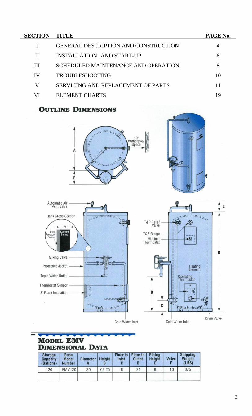
GENERAL DESCRIPTION This manual describes a packaged electric water heater system designed to meet the requirements of ANSI Z358.1-1998 for tepid water delivery to an emergency drench system. The complete assembly consists of the storage tank, immersion electric heating element(s), thermostat(s), safety relief valve, safety high temperature cut out, mixing valve, and any other required electrical operating control. Optional equipment may be supplied with your unit. Please consult the product drawing for details specific to your assembly. The unit is factory assembled, insulated, jacketed, wired, tested, and ready for electrical and plumbing service connections. CONSTRUCTION TANK The standard storage tank is constructed of steel and internally lined with specially formulated Hydrastone cement to a ½-inch minimum thickness. The tank is designed for a maximum allowable working pressure of 150 psi (300 psi TP). TANK CONNECTIONS The heater is supplied with separate cold water and tepid water connections. A 1-½ inch FNPT connection is supplied for the cold water inlet. The cold water is deflected by means of a baffle within the tank. A 1-¼ inch FNPT union connection is supplied at the mixing valve for tepid water. A ¾ inch FNPT connection is located on the side of the heater for mounting a combination safety temperature and pressure relief valve. An overflow line should be utilized from the relief valve outlet to a floor drain. A ¾ inch GHT connection is supplied for draining. See drawing for locations. HEATING ELEMENT The water heater is supplied with an electric immersion heating element assembly(s), composed of a copper sheathed element(s) that are brazed into a brass flange. Each assembly is fastened to a corresponding tank flange using a gasket and four (4) 3/8-16 x 1-inch long hex head steel bolts and nuts. See drawing for voltage and power ratings. CONTROL THERMOSTAT The water heater is supplied with an immersion thermostat factory preset at 170°. The immersion thermostat can be adjusted through a range of 100° - 180° F and is adjustable with a flat tip screwdriver. TEMPERATURE HIGH LIMIT SWITCH As a safety device, a surface mounted high temperature cut-off switch with manual reset is supplied. As an option, an immersion high temperature cut-off switch with manual reset may be provided. Either high temperature cut-out switch is factory preset at 190°F. In the event of an over-temperature condition, the thermostat will disengage the power from the system. The high limit must be manually reset thereafter to restart the heater.
Manual Reset Surface Mounted High Immersion High Temp. Cut-Off Switch Temp. Cut-Off Switch (Standard) (Optional)

5
MIXING VALVE The mixing valve is a triple redundant, thermostatic pressure balanced valve specifically designed for emergency safety shower/face/eyewash application. The valve is factory mounted and piped to the water heater. The mixing valve meets OSHA and ANSI requirements and is capable of providing 85°F output regardless of inlet pressure and temperature variations, and the temperature setting is tamper proof and can not be inadvertently adjusted in the field. Alternate mixing valve tepid water set temperatures of 70°, 75°, 80°, and 90°F are available. AUTOMATIC AIR VENT VALVE An automatic air vent valve is supplied in the highest point of the system to allow trapped air in the system to escape.
DUAL TEMPERRATURE AND PRESSURE GAUGE A combination temperature (70° - 250° F) and pressure (0 – 200 psi) gauge with 3-inch dial is installed in the tank. OUTER SHELL AND INSULATION The tank is encapsulated in 3-inch thick polyurethane foam insulation. The insulation is protected by a high impact non-corroding colorized composite protective jacket. OPTIONS The following optional features may be included in your water heater. Reference included drawing specific to your heater for further details. Low Temperature Alarm Dry Contacts A low temperature thermostat is available with dry contacts to remotely alarm when the tank water temperature falls below a specified setpoint. The low temperature thermostat is adjustable from 30-110°F. High Temperature Alarm Dry Contacts High temperature alarm dry contacts are available with the optional immersion high limit cut-out switch to remotely alarm when the tank water temperature rises above the high limit setpoint. Outdoor Weather Package The optional outdoor weather package includes a 304 stainless steel outer protective jacket, a weather resistant electrical housing, and 6” high tank legs to raise the entire unit off the floor. Flow Alarm An optional flow alarm may be included to signal that there is tepid water flow. Explosion Proof Construction The system may be constructed for installation in a hazardous location. Mixing Valve Enclosure An optional fiberglass enclosure provides added protection for the mixing valve in outdoor environments. Multiple Units Multiple units may be piped together to meet the needs of larger demand systems. Alternate Heat Sources An optional heat exchanger may be factory installed to utilize steam or boiler water as the heating source.

6
SECTION II – INSTALLATION
WARNING / CAUTION DO NOT TURN ON THE ELECTRIC POWER SUPPLY to this equipment until heater is completely filled with water and all air has been released. If the heater is NOT filled with water when the power is turned on, the heating elements will burn out. For protection against excessive pressures and temperatures, local codes require the installation of a temperature-and-pressure (T&P) relief valve certified by a nationally recognized laboratory that maintains periodic inspection of production of listed equipment of materials, as meeting the requirements for Relief Valves and Automatic Gas Shutoff for Hot Water Supply Systems. ANSI Z21.22-1971. THE CUSTOMER IS RESPONSIBLE TO PROTECT PROPERTY AND PERSONNEL FROM HARM WHEN THE VALVE FUNCTIONS. All water heaters have a risk of leakage at some unpredictable time. IT IS THE CUSTOMER'S RESPONSIBILITY TO PROVIDE A CATCH PAN OR OTHER ADEQUATE MEANS, SO THAT THE RESULTANT FLOW OF WATER WILL NOT DAMAGE PROPERTY. WATER HEATER PLACEMENT
1. Place the heater on a solid foundation in a clean, dry location nearest to the point of most frequent tepid water use
2. The water heater should be protected from freezing and waterlines insulated to reduce energy and water waste.
3. Leave a minimum of 18” clearance for element withdrawal. 4. Do not install in an area where flammable liquids or combustible vapors are present,
except when installed with the explosion proof option. PIPING INSTALLATION NOTE: The most effective means for preventing deterioration from accelerated corrosion due to galvanic and stray current is the installation of dielectric fittings/unions. The installation of these fittings is the responsibility of the installing contractor.
1. Connect the cold water inlet and tepid water outlet to the appropriate connections as shown below; refer to the drawing for location and sizes.
2. Install the combination temperature and pressure safety relief valve in the tapping provided. Note that this is required by law for safety considerations.
Install into provided tapping Manual Release Lever
Temperature Probe
Outlet to floor drain Temperature and Pressure Relief Valve
3. Install a relief valve overflow pipe to a nearby floor drain. CAUTION: No valve of
any type should be installed between the relief valve and tank or in the drain line. 4. On startup, thermal expansion will cause the water to expand. Hubbell recommends
that a thermal expansion tank or supplementary pressure relief device be installed in the cold water inlet to allow for this expansion.
7
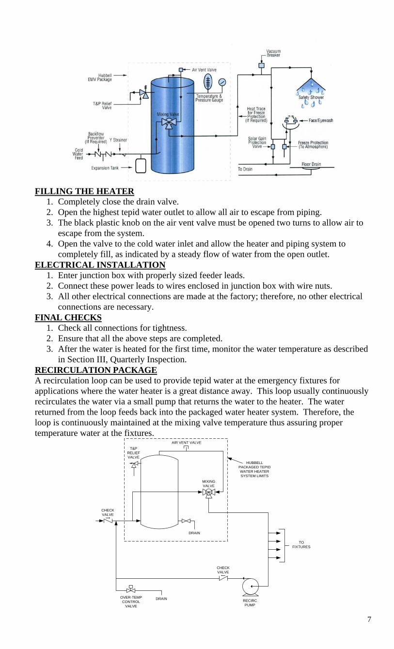
FILLING THE HEATER
1. Completely close the drain valve. 2. Open the highest tepid water outlet to allow all air to escape from piping. 3. The black plastic knob on the air vent valve must be opened two turns to allow air to
escape from the system. 4. Open the valve to the cold water inlet and allow the heater and piping system to
completely fill, as indicated by a steady flow of water from the open outlet. ELECTRICAL INSTALLATION
1. Enter junction box with properly sized feeder leads. 2. Connect these power leads to wires enclosed in junction box with wire nuts. 3. All other electrical connections are made at the factory; therefore, no other electrical
connections are necessary. FINAL CHECKS
1. Check all connections for tightness. 2. Ensure that all the above steps are completed. 3. After the water is heated for the first time, monitor the water temperature as described
in Section III, Quarterly Inspection. RECIRCULATION PACKAGE A recirculation loop can be used to provide tepid water at the emergency fixtures for applications where the water heater is a great distance away. This loop usually continuously recirculates the water via a small pump that returns the water to the heater. The water returned from the loop feeds back into the packaged water heater system. Therefore, the loop is continuously maintained at the mixing valve temperature thus assuring proper temperature water at the fixtures.
DRAIN
MIXING VALVE
T&P RELIEF VALVE
AIR VENT VALVE
HUBBELL PACKAGED TEPID WATER HEATER SYSTEM LIMITS
CHECK VALVE
CHECK VALVE
TO FIXTURES
RECIRC PUMP
DRAINOVER-TEMP CONTROL
VALVE

8
SECTION III - SCHEDULED MAINTENANCE AND OPERATION
WARNING / CAUTION Before performing any maintenance procedure, make certain power supply is OFF and cannot accidentally be turned on. MAINTENANCE AND OPERATION The water heater is automatic in its operation. It will maintain a full tank of water at the temperature setting of the thermostat. The water heater should not be turned on without first making sure that the tank is full of water and that all air has been released. FREEZING The tank should be fully drained in the event the electricity has been turned off and if there is danger of freezing. MONTHLY INSPECTION – MIXING VALVE NOTE: The mixing valve should be tested in conjunction with regular OSHA required shower/eyewash testing. These tests confirm that the equipment is safe and operational and also serve to purge potential bacteria laden water from the system. 1. Monitor temperature
a. Record all information on the Mixing Valve Inspection and Test Log, see page 11. b. Using an accurate thermometer, turn on the shower/eyewash and record the maximum
start-up spike temperature of the water. c. After a few minutes of running, record the normal temperature. d. If the temperature does not match required temperature (±3°F), recalibrate the mixing
valve. See Section V, Service and Replacement of Parts, Re-Calibrate Mixing Valve. 2. Monitor flow rate
a. OHSA/ANSI recommends a potable water system maintain a pressure of 30-psig minimum with a flow rate of 20-GPM minimum to a shower head and 3-GPM minimum to an eye/face wash fixture.
b. One simple method of testing is to collect the water in a 5-gallon container. At the required flow rate, the shower head will fill the container in approximately 15 seconds and the eye/face wash will fill the container in approximately 15 seconds.
QUARTERLY INSPECTION 1. Monitor thermostat
a. Let water heater completely heat to a designated thermostat setting. b. After thermostat satisfies (that is, when the thermostat actually clicks off), draw water
from the relief valve. c. Compare water temperature of drawn water to the temperature setting of the
thermostat when it satisfies. Normal variation between the two points is approximately + 7°F.
d. If these two readings do not coincide within acceptable tolerances and verification has been made of the accuracy of the temperature-reading gauge, replace the thermostat.
2. Lift test lever on relief valve and let water run through valve for a period of approximately 10 seconds. This will help flush away any sediment that might build up in water passageways.
3. Inspect element flange for leakage as follows: a. Shut off Power Supply. b. Remove element housing cover. c. Visually inspect heating element gasket for evidence of leaks. d. Rub finger around gasket that is between the heating element and tank flange for any
evidence of moisture. If moisture is present or a water drip is observed, follow procedure outlined in Section V.
4. Check for loose electrical connections. Tighten as necessary.

9
ANNUAL INSPECTION 1. Flush tank as follows
a. Shut off power supply. b. Close valve on hot water outlet piping. c. Open valve on drain piping. d. Cold water inlet line pressure will be strong enough to flush sediment from the bottom
of the tank out through the drain. Let water run for 3-4 minutes. e. Close drain valve. f. Open hot water valve. g. Turn power supply ON.
MIXING VALVE INSPECTION AND TEST LOG
COMPANY: HEATER SERIAL NUMBER:
DATE START-UP
SPIKE OUTPUT
TEMPERATURE COMMENTS TESTED
BY

10
SECTION IV – TROUBLESHOOTING
Symptom Probable Cause Corrective Action / Remedy No hot water in tank
Circuit breaker tripped at source.
Reset circuit breaker.
High limit switch tripped. Reset high limit switch. Loose wires. Torque screws holding wires. Heating element inoperable. Check heating element operation by
clamping an Amprobe around each wire to the element. The ampere reading should agree with the nameplate ‘AMP’ figure.
Low line voltage. Have source electrical system checked by an electrician.
Faulty thermostat. Move thermostat dial through full range. A definite ‘click’ should be heard. If not, replace thermostat.
Water temperature in tank below settings at all times
Faulty thermostat. Check thermostat adjustment. Monitor thermostat as described in Section III, Quarterly Inspection. Replace if necessary.
Heating element not working on all phases
Check to see that heating element is working on all phases, by checking the resistance (ohms) value for each element and comparing with the chart included in Section VI.
Heater improperly sized Verify heater is properly sized for the flow rate and temperature rise of your system. Replace elements with proper size as necessary.
Relief valve discharges continuously
Excessive temperature or pressure in tank
Temperature and pressure relief valves are made to operate if the water temperature exceeds 210°F or water pressure exceeds the pressure rating of the safety relief valve. If trouble is excessive temperature, then thermostat is not shutting off at the right setting and thermostat must be replaced.
Tepid water temperature too hot
Blockage in cold water inlet to mixing valve
Disconnect mixing valve and clean out cold water inlet pipe.
Mixing valve out of calibration
Re-calibrate mixing valve as described in Section V, Service and Replacement of Parts, Re-Calibrate Mixing Valve.
Tepid water temperature too cold
Blockage in hot water inlet to mixing valve
Disconnect mixing valve and clean out hot water inlet pipe.
Mixing valve out of calibration
Re-calibrate mixing valve as described in Section V, Service and Replacement of Parts, Re-Calibrate Mixing Valve.
11
SECTION V - SERVICING & REPLACEMENT OF PARTS
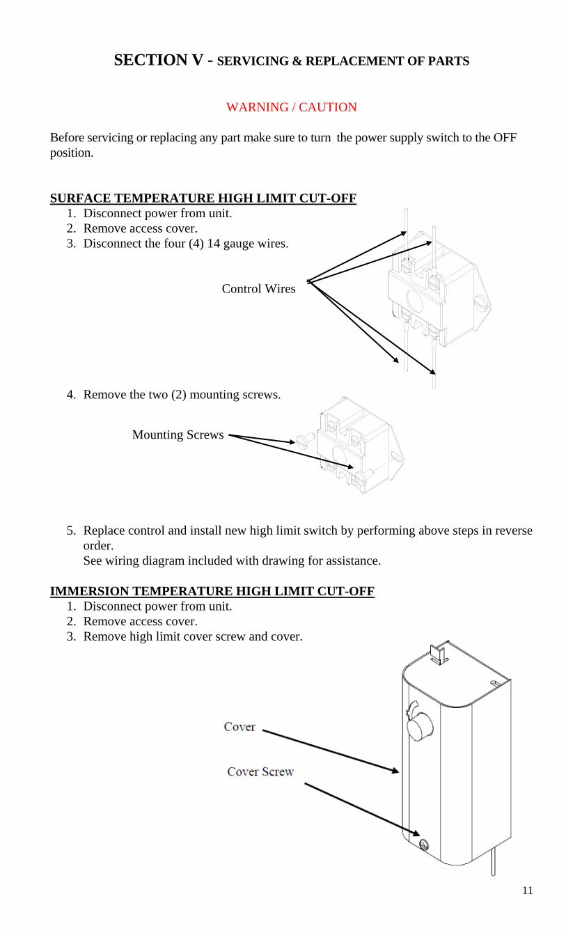
WARNING / CAUTION Before servicing or replacing any part make sure to turn the power supply switch to the OFF position. SURFACE TEMPERATURE HIGH LIMIT CUT-OFF
1. Disconnect power from unit. 2. Remove access cover. 3. Disconnect the four (4) 14 gauge wires.
Control Wires
4. Remove the two (2) mounting screws.
5. Replace control and install new high limit switch by performing above steps in reverse order. See wiring diagram included with drawing for assistance.
IMMERSION TEMPERATURE HIGH LIMIT CUT-OFF
1. Disconnect power from unit. 2. Remove access cover. 3. Remove high limit cover screw and cover.
Mounting Screws
12
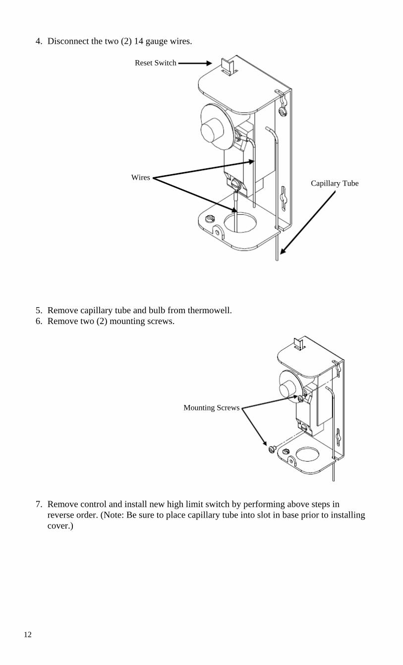
4. Disconnect the two (2) 14 gauge wires.
5. Remove capillary tube and bulb from thermowell. 6. Remove two (2) mounting screws.
7. Remove control and install new high limit switch by performing above steps in reverse order. (Note: Be sure to place capillary tube into slot in base prior to installing cover.)
Reset Switch
Wires Capillary Tube
Mounting Screws

13
SINGLE PHASE HEATING ELEMENT 1. Disconnect power from unit. 2. Shut off incoming water supply. 3. Attach hose to drain connection. 4. Lift manual release lever on relief valve to let air into system or break union on
outgoing water line. 5. Drain water from tank. 6. Disconnect the wires from the heating element terminals.
Tank Flange Wires
7. Remove the 3/8-16 nuts. 8. Withdraw element assembly and remove gasket.
9. Install new gasket and insert new heating element. 10. Rewire element according to type of unit as shown
in your drawing.
11. Fill tank and check around gasket for any leaks.
Element Assembly
Nuts
Gasket
14
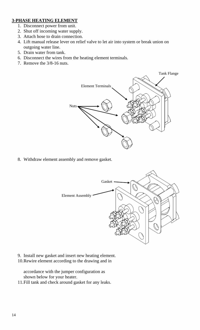
3-PHASE HEATING ELEMENT 1. Disconnect power from unit. 2. Shut off incoming water supply. 3. Attach hose to drain connection. 4. Lift manual release lever on relief valve to let air into system or break union on
outgoing water line. 5. Drain water from tank. 6. Disconnect the wires from the heating element terminals. 7. Remove the 3/8-16 nuts.
8. Withdraw element assembly and remove gasket.
9. Install new gasket and insert new heating element. 10. Rewire element according to the drawing and in
accordance with the jumper configuration as shown below for your heater.
11. Fill tank and check around gasket for any leaks.
Tank Flange
Element Terminals
Nuts
Gasket
Element Assembly

15
3-PHASE ELEMENT JUMPER CONFIGURATION
IMMERSION THERMOSTAT
1. Disconnect power from unit. 2. Remove access cover and locate
thermostat. 3. Remove high limit cover screw and
cover.
Cover
Cover Screw
16
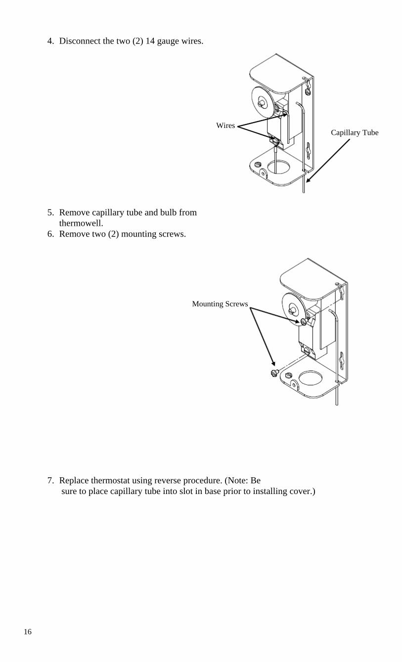
4. Disconnect the two (2) 14 gauge wires.
5. Remove capillary tube and bulb from
thermowell. 6. Remove two (2) mounting screws.
7. Replace thermostat using reverse procedure. (Note: Be sure to place capillary tube into slot in base prior to installing cover.)
Wires Capillary Tube
Mounting Screws
17
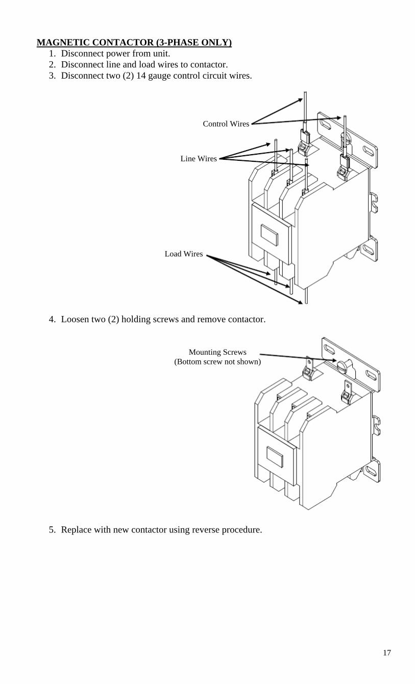
MAGNETIC CONTACTOR (3-PHASE ONLY) 1. Disconnect power from unit. 2. Disconnect line and load wires to contactor. 3. Disconnect two (2) 14 gauge control circuit wires.
4. Loosen two (2) holding screws and remove contactor.
5. Replace with new contactor using reverse procedure.
Control Wires
Line Wires
Load Wires
Mounting Screws (Bottom screw not shown)

18
RELIEF VALVE 1. Disconnect power from unit. 2. Shut off incoming water supply. 3. Lift test lever on relief valve to relieve pressure in tank. 4. Disconnect overflow piping. 5. Unscrew relief valve, remove assembly and replace with new one. 6. Connect overflow piping. 7. Turn on incoming water supply and check for leaks. 8. Turn safety switch to ON position.
19
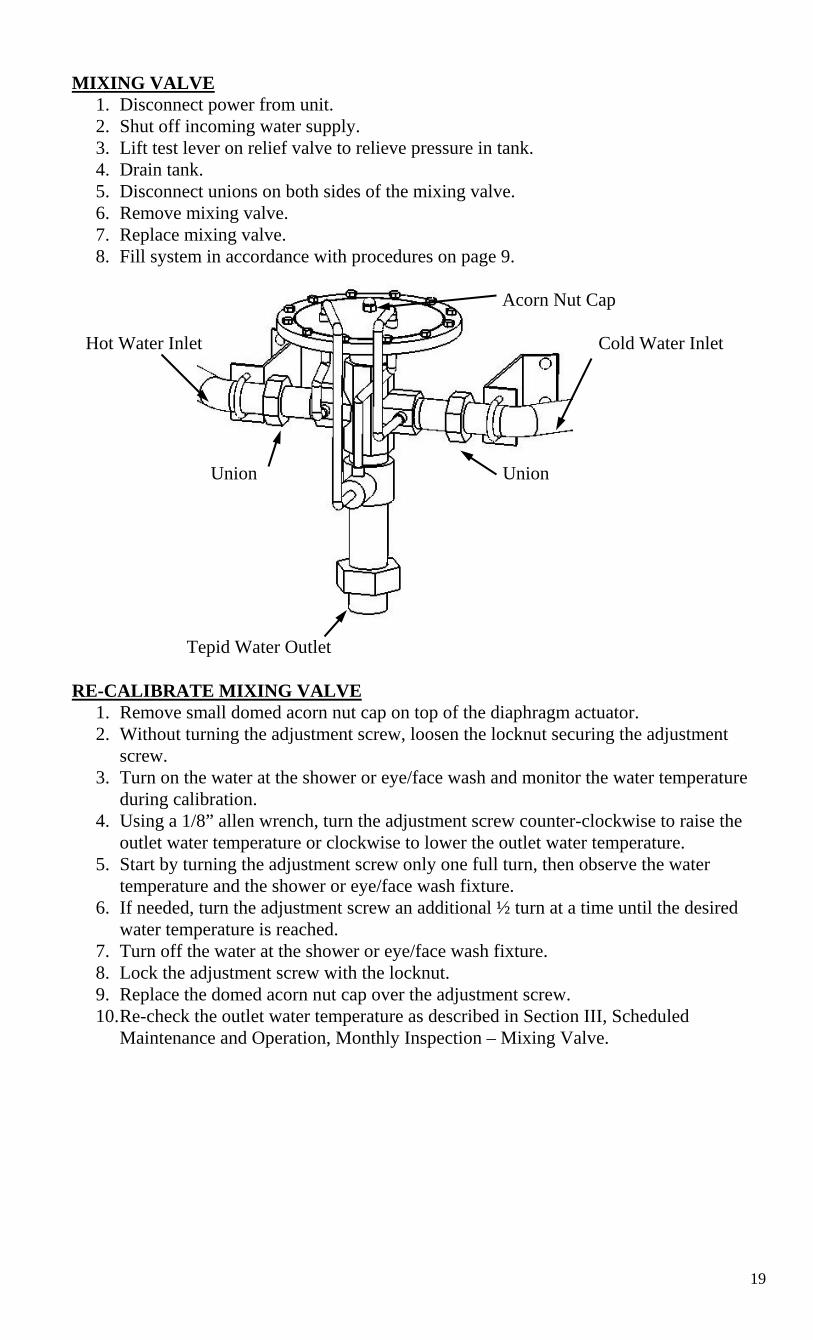
MIXING VALVE 1. Disconnect power from unit. 2. Shut off incoming water supply. 3. Lift test lever on relief valve to relieve pressure in tank. 4. Drain tank. 5. Disconnect unions on both sides of the mixing valve. 6. Remove mixing valve. 7. Replace mixing valve. 8. Fill system in accordance with procedures on page 9.
Acorn Nut Cap Hot Water Inlet Cold Water Inlet Union Union
Tepid Water Outlet
RE-CALIBRATE MIXING VALVE 1. Remove small domed acorn nut cap on top of the diaphragm actuator. 2. Without turning the adjustment screw, loosen the locknut securing the adjustment
screw. 3. Turn on the water at the shower or eye/face wash and monitor the water temperature
during calibration. 4. Using a 1/8” allen wrench, turn the adjustment screw counter-clockwise to raise the
outlet water temperature or clockwise to lower the outlet water temperature. 5. Start by turning the adjustment screw only one full turn, then observe the water
temperature and the shower or eye/face wash fixture. 6. If needed, turn the adjustment screw an additional ½ turn at a time until the desired
water temperature is reached. 7. Turn off the water at the shower or eye/face wash fixture. 8. Lock the adjustment screw with the locknut. 9. Replace the domed acorn nut cap over the adjustment screw. 10. Re-check the outlet water temperature as described in Section III, Scheduled
Maintenance and Operation, Monthly Inspection – Mixing Valve.
20
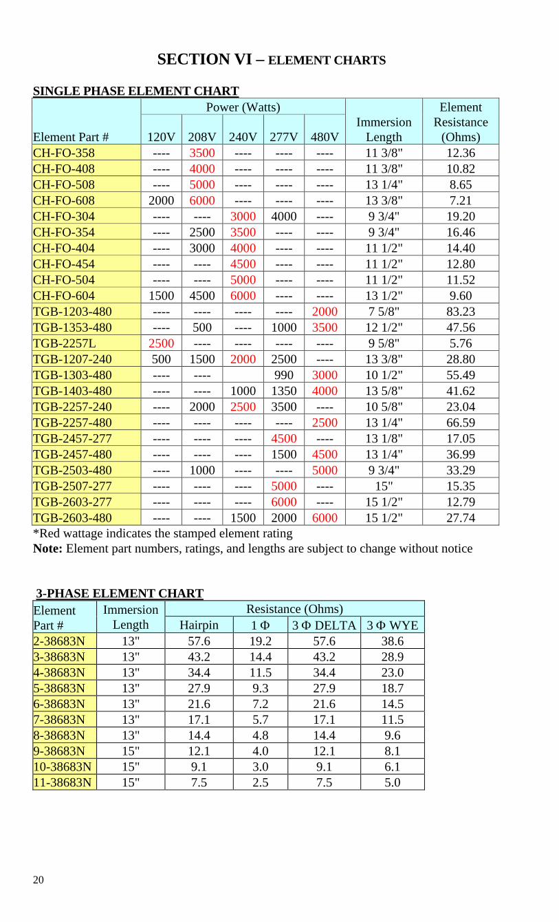
SECTION VI – ELEMENT CHARTS
SINGLE PHASE ELEMENT CHART
Element Part #
Power (Watts) Immersion
Length
Element Resistance
(Ohms) 120V 208V 240V 277V 480V CH-FO-358 ---- 3500 ---- ---- ---- 11 3/8" 12.36 CH-FO-408 ---- 4000 ---- ---- ---- 11 3/8" 10.82 CH-FO-508 ---- 5000 ---- ---- ---- 13 1/4" 8.65 CH-FO-608 2000 6000 ---- ---- ---- 13 3/8" 7.21 CH-FO-304 ---- ---- 3000 4000 ---- 9 3/4" 19.20 CH-FO-354 ---- 2500 3500 ---- ---- 9 3/4" 16.46 CH-FO-404 ---- 3000 4000 ---- ---- 11 1/2" 14.40 CH-FO-454 ---- ---- 4500 ---- ---- 11 1/2" 12.80 CH-FO-504 ---- ---- 5000 ---- ---- 11 1/2" 11.52 CH-FO-604 1500 4500 6000 ---- ---- 13 1/2" 9.60 TGB-1203-480 ---- ---- ---- ---- 2000 7 5/8" 83.23 TGB-1353-480 ---- 500 ---- 1000 3500 12 1/2" 47.56 TGB-2257L 2500 ---- ---- ---- ---- 9 5/8" 5.76 TGB-1207-240 500 1500 2000 2500 ---- 13 3/8" 28.80 TGB-1303-480 ---- ---- 990 3000 10 1/2" 55.49 TGB-1403-480 ---- ---- 1000 1350 4000 13 5/8" 41.62 TGB-2257-240 ---- 2000 2500 3500 ---- 10 5/8" 23.04 TGB-2257-480 ---- ---- ---- ---- 2500 13 1/4" 66.59 TGB-2457-277 ---- ---- ---- 4500 ---- 13 1/8" 17.05 TGB-2457-480 ---- ---- ---- 1500 4500 13 1/4" 36.99 TGB-2503-480 ---- 1000 ---- ---- 5000 9 3/4" 33.29 TGB-2507-277 ---- ---- ---- 5000 ---- 15" 15.35 TGB-2603-277 ---- ---- ---- 6000 ---- 15 1/2" 12.79 TGB-2603-480 ---- ---- 1500 2000 6000 15 1/2" 27.74 *Red wattage indicates the stamped element rating Note: Element part numbers, ratings, and lengths are subject to change without notice 3-PHASE ELEMENT CHART Element Part #
Immersion Length
Resistance (Ohms) Hairpin 1 Φ 3 Φ DELTA 3 Φ WYE
2-38683N 13" 57.6 19.2 57.6 38.6 3-38683N 13" 43.2 14.4 43.2 28.9 4-38683N 13" 34.4 11.5 34.4 23.0 5-38683N 13" 27.9 9.3 27.9 18.7 6-38683N 13" 21.6 7.2 21.6 14.5 7-38683N 13" 17.1 5.7 17.1 11.5 8-38683N 13" 14.4 4.8 14.4 9.6 9-38683N 15" 12.1 4.0 12.1 8.1 10-38683N 15" 9.1 3.0 9.1 6.1 11-38683N 15" 7.5 2.5 7.5 5.0

21

22
P.O. BOX 288 STRATFORD, CT 06615-0288
PHONE: (203) 378-2659 FAX: (203) 378-3593
INTERNET: http://www.hubbellheaters.com/