operating and maintenance manual for mp … and maintenance manual for mp oscillating piston...
TRANSCRIPT

Operating and MaintenanceManual for MP OscillatingPiston Flowmeter
M150Rev. AMP Oscillating Piston Flowmeters:
1/2″ Type MP1″ Type MP2″ Type MP3″ Type MP


TABLE OF CONTENTS
DESCRIPTION PAGE
General Information .............................................................................................. 1
Installation ............................................................................................................. 1
Calibration ............................................................................................................. 2
Register Maintenance .......................................................................................... 3
Pulsmate Electronic Register .............................................................................. 3
800 Series Register ............................................................................................. 4
1″ MP w/Double Trip Auto-Stop Valve .............................................................. 5
2″ MP w/Single Trip & Double Trip Auto-Stop Valve .................................. 6-8
3″ MP ............................................................................................................. 9-13
600 Series Register ........................................................................................... 14
Operational Checks ............................................................................................ 15
Gear Train Maintenance .................................................................................... 15
Cleaning the Flowmeter ..................................................................................... 16
General Maintenance ......................................................................................... 17
Troubleshooting .................................................................................................. 18


GENERAL INFORMATION
This manual is intended to be a guide for the proper operation and maintenanceof the 1/2″, 1″, 2″ and 3″ MP Flowmeters and accessories, as described in FormTS150.
The MP Flowmeter is a carefully designed flowmeter based on the tried andtrue oscillating piston principle and incorporates the very best materials and designfeatures available. In the MP Flowmeter, an oscillating piston is contained withina rugged main housing which also serves as the measuring chamber. This approachsimplifies the design and minimizes flowmeter maintenance.
The oscillatory motion of the piston rotates a drive arm which is part of a magneticdrive assembly contained within the cover of the flowmeter. The rotation of the magnetin this assembly causes rotation of a similar magnet in either an external gear trainor in a totalizer register.
Various readout options and accessories are available.
INSTALLATIONPlease review the following installation guidelines carefully before installing your
flowmeter. Afterwards, if you have questions or concerns, please contact your localActaris Neptune distributor for assistance.
STRAINERPlan the installation in such a way as to allow a strainer to be coupled directly
to the inlet of the flowmeter. Where this is not possible, any piping before the flowmetershould be thoroughly cleaned out. The use of at least a 40 mesh strainer is requiredto validate the warranty.
Be careful to allow room for easy removal of the strainer basket.
AIR/AIR RELEASEThe presence of air in the system can cause overspeeding and damage to
the flowmeter. Air will also cause the register to over record. The use of an airrelease will assist in preventing these problems. Also, the use of a venting valvewill aid in preventing air related problems during start-up of flow.
Air releases cannot be supplied for all liquids, but where an air release valveis used, it should be installed in a position as close as possible to the inlet of theflowmeter. This will insure the removal of the greatest amount of air from the liquidbefore metering.
VALVESThe metering system should be furnished with and controlled by a shut-off valve
on the downstream side of the flowmeter to insure that the piping and the flowmeterare filled at all times. A valve is needed to operate flow to avoid overspeeding inmost installations.
CONNECTIONS/PIPINGUse pipe compound sparingly on male threads only.
A bypass connection installed around the flowmeter should be monitored fre-quently since the valve in such a bypass may eventually leak, work open, or beleft open.
1/2″″″″″, 1″″″″″, 2″″″″″ and 3″″″″″ MP FLOWMETERS
GENERAL MAINTENANCE
INSTALLATION
Before Installing The Flowmeter
Piping
Page 1

Page 2
Secure the connecting piping firmly to prevent strain on the flowmeter casing.Use self-aligning couplings and expansion joints in long piping runs to allow forexpansion and contraction caused by temperature changes.
Provide the metering system with means for pressure relief or escape of trappedliquid caused by temperature expansion. Pressure build-up can be eliminated bythe use of valves equipped with pressure relief at selected sections of line that maybe blocked between valves. If the flowmeter is to be operated under extremes ofenvironment (dirt, dust, water, freezing, etc.) an enclosure or other protection shouldbe provided.
Thoroughly clean system and all piping, especially on the inlet side of theflowmeter. When possible, install a length of pipe (spool-piece) in place of the flowmeterand flush out the piping thoroughly before the flowmeter is installed. The majorityof service calls on new installations are eliminated if these directions are followed.
Connect the flowmeter so that its inlet and outlet are correctly located. (Theseare clearly marked.) Do not install the flowmeter backwards. Should it be necessaryto change the direction in which the register will face, turn it as described under“Register Maintenance.”
When the installation is still new, clean the strainer frequently. After the systemhas had a chance to be thoroughly flushed out, only periodic cleaning is necessary.
CALIBRATION
When checking the calibration of the flowmeter, use a calibrated test measureof sufficient size that the flowmeter will operate at a normal flow rate for at leastone (1) minute. For checking this flowmeter, use a 10 gallon volumetric test measureof approved design (for 1/2” meter) or use a 100 or 300 gallon volumetric test measureof design (a container with a conical upper portion terminating in a long narrowneck that is fitted with a sight gauge.)
Erratic registration is an indication of trouble in the system, and is usually causedby air or dirt in the measuring chamber. Do not try to correct this by recalibratingthe flowmeter, but first check for the presence of air in the line; then, if the troublehas not been found, clean the flowmeter as directed.
Over-registration is an indication of air, whereas under-registration is generallycaused by dirt or pipe scale in the measuring chamber, by the liquid bypassingthe flowmeter in some manner, or by a damaged or worn internal mechanism.
Consistent over-registration or under-registration indicates need for recalibration.See Form TSG-310 for recalibration procedures. These forms can be obtained fromyour nearest Actaris Neptune distributor, or contact Actaris Neptune, 1310 EmeraldRoad, Greenwood, SC 29646.
When Installing
Cleaning The Strainer
CALIBRATION
Erratic Registration
Consistent Over- orUnder-Registration

Page 3
REGISTER MAINTENANCE
Register parts are such that only minor field repairs are advisable. When aregister is in need of extensive service or repair other than that for which instructionis given here, it is recommended that the register be returned to the nearest ActarisNeptune distributor for repair. If a replacement register is needed, be sure to specifythe exact model of the register replaced as well as the change gears in the register.See parts lists, forms: P390 and P300.
PULSMATE ELECTRONIC REGISTER
1/2″″″″″ MP Meter:
Remove the set screw from the Pulsmate and twist the register 1/8th turn counterclockwise to release the retaining spring. The Pulsmate is now free and can bewithdrawn from the meter cover. The Pulsmate can be remounted in any one of4 positions at 90˚ intervals on the meter cover.
1″″″″″ – 3″″″″″ MP Meter:
The Pulsmate is fixed to the meter cover by 2 clamp rings secured by 4 bolts.To remove the register from the meter, loosen the screws and disengage the clamprings from the groove in the Pulsmate body. The Pulsmate can be positioned atany angle prior to clamping to the meter cover.
PULSMATE MAINTENANCEThe only scheduled maintenance for the PULSMATE register is periodic re-
placement of the battery.
Battery Replacement:The PULSMATE has a battery monitor feature that illuminates when the lithium
battery voltage approaches its end of life. A descriptor, “BAT”, illuminates when thebattery voltage falls below this predetermined value. The low battery detector operatescorrectly with all power options.
The battery should be replaced within several weeks of the first occurrenceof low battery warning, “BAT”. Left unattended, the unit may become inaccurate,cease to operate or loose setup information or malfunction.
For additional Pulsmate Electronic Register information, see form M-302. Thisform can be obtained from your nearest Actaris Neptune distributor, or by contactingActaris Neptune.
REGISTER MAINTENANCE
PULSMATE ELECTRONICREGISTER
Removing The Pulsmate From TheMeter
MAINTENANCE

800 SERIES REGISTER
Loosen the two clamp screws on lower front of the register. Lift the registeroff. On Auto-Stop models the valve linkage must first be disconnected. (Removecotter pin and washer at valve end.)
When one register is removed and another substituted, (1) Check the numberof teeth on the change gears. They must be the same as the gears on the oldregister and on the same respective spindles. The number of teeth is stampedon each gear. To remove these gears, close the split end of the spindle with apair of pliers and pull off the gear. After putting on a gear, spread the end of thespindle slightly. (2) If a gear shifter is installed, make sure that the position is thesame on the new register as on the old one. Each hole is lettered for convenience.
Register masks are made of plastic and require special treatment. Instructionsfor cleaning are given below:
If the mask becomes soiled with grease and oil, solvents for these substances,such as kerosene or naphtha, may be used to remove dirt. However, sprays thatare commonly employed in cleaning glass windshields must not be used as cleaners.
A water solution of nonabrasive soap is recommended for washing grease, oilor dirt from the mask. It is then cleaned by rubbing gently with a soft cloth, in amanner similar to cleaning window glass, rinsing the mask in clean water, and finallydrying.
Scouring cleanser and similar material must not be used in cleaning the mask,since they contain abrasives that scratch the surface.
The use of solvents, such as acetone, ethyl acetate, benzene and ethylenedichloride to brighten the surface of the mask is never recommended since thesesubstances soften the surface of the plastic.
Note: Large magnetic drive assembly accompanies 800 series register.
TO ROTATE REGISTER (1″″″″″ & 2″″″″″ MP)When the flowmeter is assembled as a Left Hand assembly and it is desired
to change it to a Right Hand assembly, or vice versa, proceed as follows:
VIEW LOOKING AT BACK OF REGISTER
Left Hand Assembly Right Hand Assembly
Page 4
800 SERIES REGISTER
To Remove Register FromFlowmeter
To Clean Register Masks
TO ROTATE THE REGISTER
Figure 1
Figure 1

1. Remove cotter pins (E) from valve linkage.
2. Unscrew the outside register link lock nut (P) and remove connecting rod(G).
3. Remove register link (N), rotate 1/2 turn and reassemble onto register asdescribed in appropriate valve adjustment instructions. (Page 6)
4. Loosen two clamp screws on lower front of register, lift register up andturn register 180°.
5. Remove four handle housing assembly hex screws (C) and remove handlehousing assembly from valve.
6. Remove valve handle set screw (B) and slide handle off bushing. Removetwo cam retaining screws (not shown). Remove shaft seal plug (D). Dis-assemble valve operating shaft and valve operating cam. Reassemble valveoperating shaft and install valve operating cam in the reverse direction.Reinstall two cam retaining screws and shaft seal plug. Reinstall housingassembly with valve operating cam acting on pilot rod. Secure with fourhex screws (C). Reassemble valve handle (A) on knurled knob in positionas shown for specific assembly.
After completing the above instructions, the valve linkage must be adjusted inaccordance with the procedure for the specific type valve as outlined on the followingpages.
1″″″″″ MP FLOWMETER WITH SINGLE TRIP ANDDOUBLE TRIP AUTO-STOP VALVE
Note: Before any adjustment of the Double Trip or Single Trip Auto-Stop Valveis made, be sure that the Auto-Stop setting wheels indicate a quantity, other thanzero, to insure that the trip mechanism of the register is in proper position.
To Adjust Double Trip Valve Linkage With Valve At Outlet of Flowmeter (SeeFigure 2)
1. Depress the emergency stop button on the register and turn the shaft (O)clockwise (as viewed from rear of register.)
2. Assemble register link (N) on knurled knob in position as shown for specificassembly. (See Figure 2). Arm should move an equal distance each sideof vertical center line (M) (Angle x=x).
3. Assemble one nut (P) on connecting rod (G) and the other end of theconnecting rod to the center hole in handle (A) using washers and cotterpins (E).
4. Open valve all the way. Turn shaft (O) counter clockwise to latch up mechanism.With valve held open, tighten nut (P) against register arm link. Then assembleand tighten second nut at (P).
5. Depress the emergency stop button and allow the valve to close. At thispoint the linkage between the valve and the register must be free. If it isnot, the above adjustments must be rechecked.
6. Set the register to deliver the minimum quantity and open the valve to runproduct through the flowmeter.
7. After the initial trip occurs the valve should close to the intermediate flowposition. This rate will vary depending on product metered. If the valve closestoo far, or all the way, adjust nuts (P) to provide additional rod length.
1″″″″″ MP FLOWMETER WITHSINGLE TRIP AND DOUBLETRIP AUTO-STOP VALVE
Adjustment of 1″″″″″ DoubleTrip Auto-Stop Valve
Page 5

Page 6
8. It is sometimes necessary to change the position of the handle. This canbe done by loosening handle screw (B) and repositioning the handle asfollows: If the register mechanism will not latch up, position the handle furthertoward the register. If the valve will not close, the handle may be positionedaway from the register. Fine adjustments may be made by changing theeffective length of connecting rod (G) utilizing nuts (P). The rod length (G)may also be varied by positioning the end of the rod in the upper or lowerholes in the valve handle.
9. The Auto-Stop trip adjusting screw should be near its mid-position. (Alsosee page 14 “To Adjust the Tripping Point.)
VIEW LOOKING AT BACK OF REGISTER
Figure 2LEFT-HAND ASSEMBLY RIGHT-HAND ASSEMBLY
2″″″″″ MP FLOWMETERS WITH SINGLE TRIPAND DOUBLE TRIP AUTO-STOP VALVES
In determining whether the metering unit is a Right Hand or Left Hand Assembly,the position of the outlet of the flowmeter as the operator faces the front of theregister, is the governing factor.
When the flowmeter is assembled as a Left Hand assembly and it is desiredto change it to a Right Hand assembly, or vice versa, proceed as follows:
1. Remove clevis pin (E) from valve link-age.
2. Unscrew the outside register link locknut (P) and remove connecting rod (G)and clevis (F) as a unit.
3. Remove register link (N), rotate 1/2 turnand reassemble onto register as de-scribed in appropriate valve adjustmentinstructions. (Pages 7 & 8.)
4. Loosen two clamp screws on lower frontof register, lift register up and turn register180°.
5. Remove operating shaft cap screw (C)on both sides.
6. Interchange connecting rod arm (H) and valve operating handle (A). The connectingrod arm must be assembled with notches (J and K) in specific relationship. (Seeitem 3 of valve adjustment instructions for details regarding position of notches.)
7. Reassemble operating shaft cap screws (C).
Figure 2
2″″″″″ MP FLOWMETERS WITHSINGLE TRIP AND DOUBLETRIP AUTO-STOP VALVES
To Rotate The Register
Figure 3
Figure 3
Left Hand Assembly

Page 7
8. Remove valve handle stop set screw (B) and screw into holes on opposite sideof valve.
After completing the above instructions, the valve linkage must be adjusted inaccordance with the procedure, for the specific type valve (i.e., Double Trip or SingleTrip) as outlined on pages 7 & 8.
Note: Before any adjustment of the Double Trip or Single Trip Auto-Stop Valveis made, be sure that the Auto-Stop setting wheels indicate a quantity, other thanzero, to insure that the trip mechanism of the register is in proper position.
1. Depress the emergency stop button on the register and turn the shaft (O)clockwise (as viewed from the rear of the register).
2. Assemble register arm (N) on knurled knob in position as shown for specificassembly. (See Figure 4). Arm should move an equal distance each sideof vertical center line (M) (Angle x=x).
3. Assemble valve arm (H) as shown for specific assembly. On the right handassembly there must be one notch between the cast mark (K) on the valvearm and the cast mark (J) on the stop plate (J and K). On the left handassembly these cast marks must be in line.
4. Assemble one nut (P) on connecting rod (G) and assemble clevis to theother end of the connecting rod a distance of 1".
5. Insert end of connecting rod through register arm link and assemble clevis(F) to valve arm (H) using upper hold. (See Figure 4). Insert clevis pin(E).
6. Open valve all the way. The opening of the valve is stopped by the setscrew (B) which should project approximately 1/8" below the lug holdingit. Turn shaft (O) counter clockwise to latch up mechanism. With valve heldopen, tighten nut (P) against register arm link. Then assemble and tightensecond nut at (P).
7. Depress the emergency stop button and allow the valve to close. At thispoint the linkage between the valve and the register must be free. If it isnot, the above adjustments must be rechecked.
8. Set the register to deliver the minimum quantity and open the valve to runproduct through the flowmeter.
9. After the initial trip occurs the valve should close to the intermediate flowposition. This rate will vary depending on product metered. If the valve closestoo far, or all the way, unscrew clevis (F) on rod (G) to hold valve openfurther. If the rate of flow is too fast during the intermediate position, turnthe clevis onto the rod to allow the valve to close further. It should notbe necessary to turn more than one turn in either direction.
10. It is sometimes necessary to change the position of set screw (B) if theclevis has been readjusted. If the register mechanism will not latch up,unscrew the set screw to allow the valve to open further. If the connectingrod (G) is under compression, when the valve is held all the way open,turn the set screw down to relieve the pressure on the register.
11. The Auto-Stop trip adjusting screw should be near its mid-position. If a smalladjustment of this screw will not permit the register to shut off “on the mark,”it is usually possible to correct this by a slight adjustment of the clevis (F).This will move the main valve nearer to or further away from its seat duringthe intermediate flow and thereby change the amount of time needed forthe valve to fully close at the last trip. (Also see page 14, “To Adjust theTripping Point.”)
Adjustment ofAuto-Stop Valve
To Adjust Double TripValve Linkage With ValveAt Outlet of Flowmeter

Page 8
VIEW LOOKING AT VIEW LOOKING ATBACK OF REGISTER BACK OF REGISTERS
Figure 4LEFT HAND ASSEMBLY RIGHT HAND ASSEMBLY
Note: If it is difficult to obtain proper rate of flow during intermediate trip positionand still have register latch up fully, check Auto-Stop valve to ensure that it is openingall the way. Check valve by removing set screw (B) and clevis (F) from valve arm;open valve as far as possible. The distance between lug on arm and lug on stopplate must be made more than 1/4″.
Note: Before any adjustment of the Double Trip or Single Trip Auto-Stop Valveis made, be sure that the Auto-Stop setting wheels indicate a quantity, other thanzero, to insure that the trip mechanism of the register is in proper position.
1. Depress the emergency stop button on the register and turn the shaft (O)clockwise.
2. Assemble register link (N) on knurled knob in position as shown for specificassembly. (See Figure 5). Arm should move an equal distance each sideof vertical center line (M) (Angle x=x).
3. Assemble valve arm (H) as shown for specific assembly. On the right handassembly there must be two notches between the cast mark (K) on thevalve arm and the cast mark (J) on the stop plate (J above K.) On theleft hand assembly there must be one notch between marks (J above K).
4. Assemble one nut (P) on connecting rod (G) and assemble clevis to theother end of the connecting rod a distance of 1".
5. Insert end of connecting rod through register arm link and assemble clevis(F) to valve arm (H) using lower hole (Y). Insert clevis pin (E).
6. Open valve all the way. The opening of the valve is stopped by the setscrew (B) which should project approximately 1/8" below the lug holdingit. Turn shaft (O) counter clockwise to latch up mechanism. With valve heldopen, tighten nut (P) against register arm link. Then assemble and tightensecond nut at (P).
7. Depress the emergency stop button and allow the valve to close. At thispoint the linkage between the valve and the register must be free. If it isnot. the above adjustments should be rechecked.
Figure 4
To Adjust Single TripValve Linkage

VIEW LOOKING AT BACK OF REGISTER
Figure 5RIGHT-HAND ASSEMBLY
TO ROTATE THE REGISTER (3″″″″″ MP)
Remove the register from the flowmeter. Two studs and two threaded holeswill be seen on the top of the gear train. To turn the register 90° transfer the studesto the empty holes. To turn the register 180°, do not change the location of thesestuds. Replace register in the desired position and tighten the screws at the frontof register.
When the flowmeter is assembled as a Right Hand Assembly (outlet and valveassembly to the right as you face the register dial) and it is desired to change toa Left Hand Assembly (outlet and valve assembly to the left as you face dial), proceedas follows:
1. Disconnect the connecting rod at “G” by removing cotter pin, washer, andclevis pin.
2. Remove the outside connecting rod nut at “F.”
3. Remove the register.
4. Remove the auto-stop valve and reposition on alternate flange connection atother side of flowmeter.
5. Replace the register to face in the desired direction.
6. Remove connecting link arm on register and reassemble it so that it is inupward position, as indicated by dotted lines on Fig. 6. Arm should be inextreme clockwise position when emergency button is depressed.
7. Remove the vale handle and connecting rod arm from valve by removingscrews at “N.”
8. Exchange the valve handle and the connecting rod arm; the connecting rodarm is to be assembled to the valve with locating marks on arm and stop platein proper relation as indicated in Figure 6.
Figure 5
TO ROTATE THE REGISTER
Non Preset Models
Preset Models
Page 9
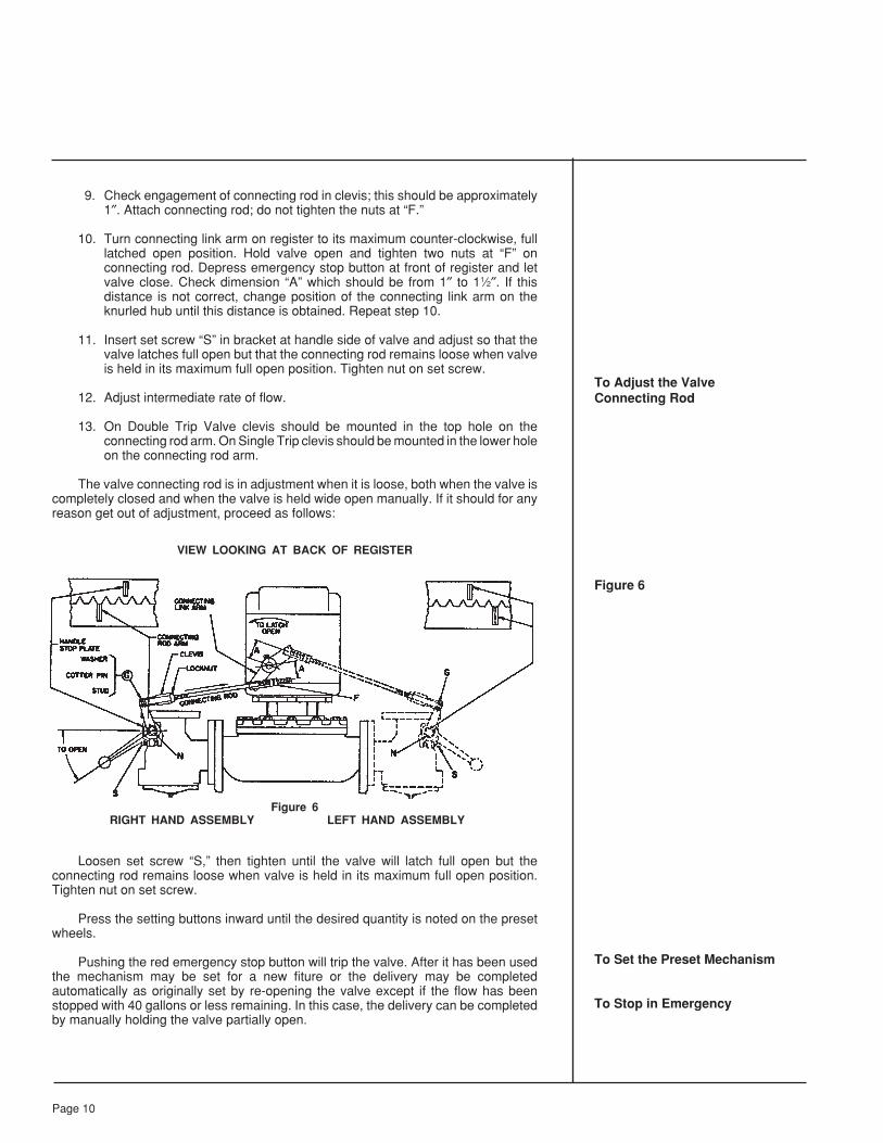
9. Check engagement of connecting rod in clevis; this should be approximately1″. Attach connecting rod; do not tighten the nuts at “F.”
10. Turn connecting link arm on register to its maximum counter-clockwise, fulllatched open position. Hold valve open and tighten two nuts at “F” onconnecting rod. Depress emergency stop button at front of register and letvalve close. Check dimension “A” which should be from 1″ to 11⁄2″. If thisdistance is not correct, change position of the connecting link arm on theknurled hub until this distance is obtained. Repeat step 10.
11. Insert set screw “S” in bracket at handle side of valve and adjust so that thevalve latches full open but that the connecting rod remains loose when valveis held in its maximum full open position. Tighten nut on set screw.
12. Adjust intermediate rate of flow.
13. On Double Trip Valve clevis should be mounted in the top hole on theconnecting rod arm. On Single Trip clevis should be mounted in the lower holeon the connecting rod arm.
The valve connecting rod is in adjustment when it is loose, both when the valve iscompletely closed and when the valve is held wide open manually. If it should for anyreason get out of adjustment, proceed as follows:
VIEW LOOKING AT BACK OF REGISTER
Figure 6RIGHT HAND ASSEMBLY LEFT HAND ASSEMBLY
Loosen set screw “S,” then tighten until the valve will latch full open but theconnecting rod remains loose when valve is held in its maximum full open position.Tighten nut on set screw.
Press the setting buttons inward until the desired quantity is noted on the presetwheels.
Pushing the red emergency stop button will trip the valve. After it has been usedthe mechanism may be set for a new fiture or the delivery may be completedautomatically as originally set by re-opening the valve except if the flow has beenstopped with 40 gallons or less remaining. In this case, the delivery can be completedby manually holding the valve partially open.
To Adjust the ValveConnecting Rod
Figure 6
To Set the Preset Mechanism
To Stop in Emergency
Page 10
Registers are shipped from the factory with the Preset mechanism adjusted to tripcorrectly at the normal rates of flow. If due to a change in the speed of closing of the valveor for any reasons the Preset does not trip off at the correct point, the trip point may beadjusted as follows:
If the valve is closing “off the mark,” either late (over-delivery) or early (under-delivery), adjust the clevis (see Fig. 6) in half-turn increments to bring the trip point tothe zero mark. For right-hand assemblies, turn the clevis to lengthen the connecting rodwhen the trip point is early, or turn to shorten if the trip point is late. For left-handassemblies turn in the opposite direction. Continue this procedure until the final trip ison or close to the zero mark. The set-screw “S” (Fig. 6) must also be readjusted asdescribed in “To Adjust the Valve Connecting Rod.” The intermediate flow rate will besatisfactory when the final trip is adjusted, as described.
Further adjustment of the trip point is possible, but is not recommended for normalapplications. The following procedure should be used only when very exact setting ofthe final trip is necessary.
Adjust the clevis, as described above,and proceed as follows:
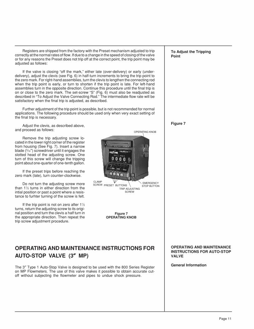
Remove the trip adjusting screw lo-cated in the lower right corner of the registerfrom housing (See Fig. 7). Insert a narrowblade (3⁄16″) screwdriver until it engages theslotted head of the adjusting screw. Oneturn of this screw will change the trippingpoint about one-quarter of one-tenth gallon.
If the preset trips before reaching thezero mark (late), turn counter-clockwise.
Do not turn the adjusting screw morethan 11⁄2 turns in either direction from theintial position or past a point where a resis-tance to furhter turning of the screw is felt.
If the trip point is not on zero after 11⁄2turns, return the adjusting screw to its origi-nal position and turn the clevis a half turn inthe appropriate direction. Then repeat thetrip screw adjustment procedure.
OPERATING AND MAINTENANCE INSTRUCTIONS FORAUTO-STOP VALVE (3″″″″″ MP)
The 3″ Type 1 Auto-Stop Valve is designed to be used with the 800 Series Registeron MP Flowmeters. The use of this valve makes it possible to obtain accurate cut-off without subjecting the flowmeter and pipes to undue shock pressure.
To Adjust the TrippingPoint
Figure 7
OPERATING AND MAINTENANCEINSTRUCTIONS FOR AUTO-STOPVALVE
General Information
Figure 7OPERATING KNOB
Page 11
CLAMPSCREW
OPERATING KNOB
PRESET BUTTONSTRIP ADJUSTING
SCREW
EMERGENCYSTOP BUTTON

OPERATIONWith the main valve and the pilot valve closed, the inlet pressure and the spring
keep the valve closed. To open the valve, the handle is lifted, lifting the pilot valveoff its seat. Inlet pressure within the cylinder is dissipated through the pilot valveto the outlet, so that a difference in pressure exists between top and bottom ofthe piston. This pressure differential will open the main valve.
To close the valve, the handle is released and the spring closes the pilot valve.Inlet pressure is admitted into the cylinder through a needle valve, and the mainvalve will move to its intermediate position, determined by the position of the pilotvalve.
In operation, the first trip will occur with 40 gallons still to be delivered. Thevalve should reach its intermeidate position with between 10 and 20 gallons stillremaining to be delivered. This will deend largely on field conditions but may beadjusted by means of the needle valve (see below “To Adjust Rate of Closing ofValve from its Full Open Position to the Intermediate Position.”) The rate of flowthrough the valve when in its intermediate position should not exceed 50 gpm. (Toadjust intermediate rate of flow see below.) This rate is controlled in the valve andwill vary, depending on such field conditions as pressure, etc. It is important thatthe needle valve be adjusted so that the valve reaches its intermediate positionbefore the final trip takes place. The final trip may be adjusted as shown on page10, Figure 6.
1. Set register setting wheels for 100 gallons and open valve. After first trip occurs(40 gallons remaining) valve closes to the intermediate position. To hold valvein its intermediate position index thousand wheel one number; this is done bypushing left hand preset button.
2. Remove cotter pin, washer, and clevis pin at “G” (figure 6, page 10) and adjustclevis by screwing off until a mere leak is passing through the valve. Turn cleviseight turns to shorten the length of the connecting rod assembly.
3. Check intermediate rate of flow. If the intermediate rate of flow exceeds 50gallons per minute, lengthen connecting rod assembly until an intermediaterate of flow of 50 gallons per minute or less is obtained.
4. Tighten clevis lock nut.5. Readjust set screw “S” as outlined on page 10, under heading “To Adjust the
Valve Connecting Rod.”
Remove seal screw (28). To make the valve close faster, turn needle valve at (N)counter-clockwise. To make the valve close slower, turn needle valve clockwise. Valveis in correct adjustment when intermediate position of vave is reached with between 10and 20 gallons still remaining to be delivered. Replace seal screw. Check final trip.
Figure 8
OPERATION
To Adjust IntermediateRate of Flow
To Adjust Rate of Closingof Valve from its Full OpenPosition to theIntermdiate Position
Figure 8
Page 12

1. To disassemble valve, remove cover (43) from end of valve. (Refer to figure9).
2. Remove cylinder retaining screw (25), seal screw (28) and needle valve (27).3. Using a 5/8″ bolt, screwed loosely into tapped hole in end of cylinder (38), pull
cylinder and piston assembly through end of valve body.4. By removing 2 screws (34), piston assembly may be removed from cylinder.
(Caution: Depress the piston to remove spring tension from screw). Pilotvalve and spring are loose and care must be taken that they are not damagedor lost.
5. Remove the four screws (39). This will release the throttling ring. Valve discmay now be replaced.
Figure 9
1. Clean all parts thoroughly.2. Replace valve disc and reassemble throttling ring to position with four screws
(39). Screws must be tightened so that metal to metal contact takes placebetween the piston and throttling ring.
3. Place pilot valve over rod and assemble spring in position over pilot valve andpost in cylinder. By locating piston ring so that the two extensions on either sideof cylinder will tend to force the piston ring into its slot, slight pressure will forcethe piston assembly into the cylinder. Two screws (34) may now be put inposition. Care must be taken that these screws enter the cast slots on eitherside of piston to prevent turning of piston within cylinder.
4. Complete piston and cylinder assembly may now be reinserted into the valvebody. Care must be taken when installing this unit so that the piston guides arenot bent, which happens if the piston is cocked in the cylinder. To prevent this,it is best to see that the piston is out all the way, resting against the two screws(34). Care must also be taken to make sure that before placing cylinderretaining screw into position, the needle valve hole in the cylinder lines up withthe proper hole in the valve body. This is shown by the word “adjust” on theoutside of casting. The retaining screw (25) may be reinstalled and needlevalve and seal screw installed.
5. Replace “O” ring cover gasket and cover.6. Connect to register and adjust linkes (Fig. 6).7. Adjust rate of closing (see page 12).
To Disassemble Valve
Figure 9
To Reassemble Valve
Page 13

1. This may be caused by worn “O” ring (19). To replace, remove screw (10),connecting rod arm, handle and stop plate (14). Then knock out drive pin (15).In doing this be sure that shaft is supported so that it will not be bent. Removefour screws and pull out shaft bearing bracket (20.1).
2. A new “O” ring (19) may now be installed. While bearing is removed, inspectshaft to be sure it is smooth and free of nicks and the “O” ring groove is clean.
3. Replace shaft bearing and assemble other parts in order removed.
Remove cover of valve and then the valve mechanism, then the piston and cylinderassembly. Inspect the valve disc for dirt or nicks. If valve disc (33) needs replacing, valvemay be disassembled and new disc installed. While valve is apart, pilot valve (32) shouldbe inspected and replaced, if necessary.
ALL MODELSThe flowmeter is shipped from the factory with Auto-Stop mechanism adjusted
to trip correctly at maximum rates of flow while the flowmeter is measuring a non-viscous liquid. Trip adjustment after final installation may be necessary due to differingflow rate and/or viscosity.
If the Auto-Stop does not trip off at the correct mark due to a change in thespeed of closing of the valve, different rates of flow, or any other reason, the adjustmentis made as follows:
Remove the screw located in the lower right corner of the front housing. Inserta medium-sized screw driver into this hole until it engages the slotted head of anadjusting screw. One turn of this screw will change the tripping point about one-quarter of one graduation of the first wheel.
If the Auto-Stop trips before reaching the zero mark, turn the adjusting screwin a clockwise direction.
If the Auto-Stop trips after the zero mark, turn the adjusting screw in a counter-clockwise direction.
In some instances on Double Trip Valves an adjustment of the valve link-age may be required in order to have the Auto-Stop at the correct point. (Seepage 7).
600 SERIES REGISTERRegister parts are such that only minor field repairs are advisable. When a
register is in need of repair or service other than that for which instruction is givenhere, it should be returned to a Actaris Neptune authorized distributor. Maintenanceof the register is limited to cleaning and to those operations which will locate thesources of possible troubles without removing the register from the flowmeter.
Remove the four register mounting screws. Rotate to the desired position andreinstall screws.
1) Remove the two cover plate screws (#1).
2) Push in reset knob and partially reset to retain shaft in reset position (#2).
If Leakage Occurs AroundValve Shaft
If Main Valve Does NotShut Off Tight
ALL MODELS
To Adjust The Tripping Point
600 SERIES REGISTER
Repair of Register
To Rotate The Register
To Remove HousingFrom Mechanism
Page 14

Page 15
3) Remove reset knob screw (#3) and four screws on bottom plate (#4).
4) Pull out on reset knob to disengage knob from shaft.
5) Loosen and slide housing to knob end and remove. Caution is advisedin removal of housing to avoid scraping visible wheels.
6) Reset shaft can be turned to normal position.
Regularly clean the housing to remove accumulations of dirt and grease, foodproducts or chemical deposits. CAUTION: Use only mild detergents and water toclean the register window. Do not use abrasives or spray type cleaners, or solventsand thinners which may soften or cloud the plastic window.
1) Remove the housing from the mechanism.
2) Blow out the dirt with compressed air. Do not use brushes.
Figure 10
Note: Large magnetic drive assembly accompanies the 600 series register.
OPERATIONAL CHECKSTwo general operational checks are performed on all Registers: calibration and
reset mechanism operation.
1) CALIBRATION CHECK – Check the calibration of the Register and recalibrate,if necessary. While pumping liquid through the flowmeter during calibration,observe that the register wheels and totalizer wheels advance properly,that registration is consistent and not erratic, and that the wheels are notdiscolored or defaced.
2) RESET MECHANISM CHECK – Check the resetting of the Register bypushing on and rotating the reset knob clockwise (as viewed from the right)to its stop, and releasing it. Note that the register wheels index to read0000.0 on the 1″ & 2″ and 00000 on the 3″, and that they align in a straightline. Note that the shutter swings freely to mask the wheels as they rotate,and drops completely when resetting is complete. (Note: Does not applyto 1/2″″″″″ MP.)
GEAR TRAIN MAINTENANCE
This gear train is constructed in such a way that the actual gear train may beremoved from the housing for general cleaning by removing the screws throughthe gear train top plate. An Actaris Neptune distributor can provide replacementgear trains if required, but proper cleaning and lubrication of the gears and shaftscan greatly extend the useful life of the gear train. We recommend removing dirtygrease or accumulation with a suitable solvent applied by a brush and relubricatingwith light grease applied to the gear shafts and bearings.
Cleaning
To Clean the Register
Figure 10
OPERATIONAL CHECKS
General
GEAR TRAINMAINTENANCE
800 Series Register
600 Series Register

Page 16
CLEANING THE FLOWMETER
To Clean Measuring Chamber Area
Figure 11
To Inspect the MagneticDrive Assembly
Replacement gear trains and related parts should be ordered from the partslist, For P150.
CLEANING THE FLOWMETER
Due to the simple desing of this flowmeter, there are very few internal partsto the flowmeter. There are no parts that would normally require maintenance orreplacement, but periodic cleaning and inspection are recommended to lengthenthe flowmeter’s useful life.
Since there is no separate measuring chamber, simply remove the eight maincase bolts and remove the cover assembly. Carefully remove the specially encap-sulated “O” ring from its groove for cleaning and re-use. With the cover removed,the piston may be easily lifted out for inspection and wiping clean. Check the controlroller to see that it fits closely but rotates easily on the chamber pin. Also checkto see that the diaphragm and seal pin fit snugly in their positions. Clean by wipingwith a soft, lint free rag all interior surfaces of the chamber area.
Figure 11
To inspect the magnetic drive assembly, remove the hex socket screws whichattach the seal plate to the cover. Then, using needlenose pliers or other suitable tool,remove the retaining ring which holds the magnetic drive assembly in position. Removethe magnetic drive assembly and inspect for excessive wear of the shaft or bearing byobserving the “wobble” of the shaft. If more than .020″ of wobble is noticed, the assemblyshould be replaced. Also notice the wear on the magnet insert curved surface. Carefullywipe all parts and make sure the assembly rotates easily before reinstalling in the cover.
Page 17
GENERAL MAINTENANCE
Sediment
Air
Water
Testing
Storage
GENERAL MAINTENANCE
To maintain the accuracy of Actaris Neptune MP Flowmeters, little is necessaryother than to see that the proper conditions of operation are observed. Once theflowmeter has been installed correctly, these conditions consist merely in guardingagainst foreign matter, such as air or sediment entering the flowmeter. However, shouldany malfunction develop, do not dismantle the flowmeter until the cause of trouble hasbeen determined. Refer to the section marked “Troubleshooting,” page 18.
The liquid passing through the MP flowmeter must be free of grit and other formsof sediment to prevent unnecessary friction and to eliminate scoring of the piston andchamber walls. Evidence of trouble from this source will be found in under-registrationof the flowmeter. Periodic cleaning and inspection of the strainer will help to insureagainst this type of trouble.
Being an instrument that measures by volume, a flowmeter will record the passageof air as well as the liquid being measured. Over-registration is the result of air in thepiping system.
Incidental water will cause no damage to the flowmeter. Possibilities of freezing,however, may be expected when water is allowed to remain in the flowmeter in exposedareas.
Water in the register will cause trouble particularly in cold weather when ice mayform and cause jamming. As in the case of most instruments, some protection for theregister should be considered when making the installation.
Instructions for testing are given in the Calibration section. Test with 10 gallon testmeasure of approved design (for 1/2” MP) or test with 100 or 300 gallon test measure ofapproved design (for larger sizes).
Before a flowmeter is put in storage it should be wiped clean and dry to preventbuildup of possibly corrosive deposits.

TroubleshootingTROUBLESHOOTING
Register Not Working When Liquid is Flowinga) Bypass around flowmeter not shut off.b) Frozen condensation inside register.c) Register in need of repair.d) Sheared key on change gear.e) Defective magnetic drive assembly.
Chronic Leakage at the Main Case “O”-Ringa) Excessive line or shock pressure.b) Damaged “O”-ring or loose bolts.
Reduction in the Flow Rate or Complete Stoppage of Dischargea) Pump bypass stuck open.b) An open valve in the piping allowing liquid to circulate around the pump.c) Worn pump.d) Blocked strainer due to sediment or frost.e) Piston in flowmeter stuck, caused by dirt. Check strainer and clean
measuring chamber.
Over-Registration – ErraticAir entering system and passing through flowmeter.
Under-Registration – Erratica) Dirt in measuring chamber.b) Badly worn control roller or diaphragm.c) Flowmeter casing distorted or damaged.d) Leakage around the flowmeter due to partly open bypass valve.
Consistent Over- or Under-RegistrationFlowmeter in need of calibration.
Page 18
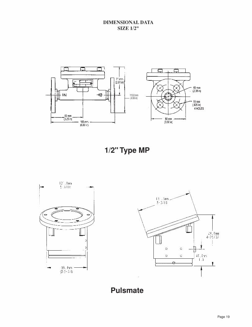
1/2" Type MP
DIMENSIONAL DATASIZE 1/2"
Pulsmate
115.8 mm(4.56 in)
Page 19

Page 20
1″″″″″ DIMENSIONS
1″″″″″ Type MP with 800 SeriesRegister and AirRelease/Strainer
1″″″″″ Type MPwith 800 Series Register
and Auto-Stop Valve
27 mm(1.06 in)
76 mm(3 in)
1" Type MP with 600 SeriesRegister and Model 45
Pulse Transmitter
7/825/841/4
63/4
65/16
11/16 DIA
5/8 DIA (4 HOLES EQUALLYSPACED ON 31/8 DIA B C )
45°
313/81/4 - 20 UNC - 28
3/4 TAPPED DEPTH2 HOLES EACH END
23/8
41/4 DIA
57/8
9/16
83/8
41/2
43/16
9/16
81/2
57/845/16
31/2
15/8
ALLOW 2 INCHCLEARANCEFOR REMOVINGREGISTER
9
19 mm(.75 in)
6.35 mm (.25 in) 20 UNC - 2B19 mm (0.75 in) TAPPED DEPTH(2 HOLES)
27 mm (1.06 in)

Page 21
2″″″″″ DIMENSIONS
2″″″″″ Type MP with 600 Series Register and Model 45 Pulse Transmitter
2″″″″″ Type MP with 800 Series Register and Air Release/Strainer
2″″″″″ Type MP with 800 Series Register and Auto-Stop Valve
168.3 mm (6.58 in)

Page 22
3″″″″″ DIMENSIONS
3″″″″″ Type MP with 800 Series Register and Auto Stop Valve
243 mm(9.56 in)
3″″″″″ Type MP with 600 Series Register
4.03 mm (15.88 in)
149.2 mm(5.78 in)
66.8 mm
(2.63 in)
248 mm(9.75 in)


U.S.A./International1310 Emerald RoadGreenwood, SC 29646-9558Tel.: Toll-Free (800) 833-3357
(864) 223-1212Fax: (864) 223-0341
© 2003 Actaris Neptune Liquid Measurement Division 1000 05/03
Specifications subject to change without prior notification.
AB
S Quality Evaluations, Inc.
Quality Assurance Certif
icatio
n
Certificate Number: 30201