operating and maintenance manual electric motor powered ... · operating and maintenance manual...
TRANSCRIPT

Operating and Maintenance Manual Electric Motor Powered & Without Power
Diaphragm Pumps
Series 55A
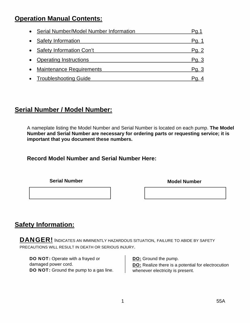
Operation Manual Contents:
• Serial Number/Model Number Information Pg.1
• Safety Information Pg. 1
• Safety Information Con’t Pg. 2
• Operating Instructions Pg. 3
• Maintenance Requirements Pg. 3 • Troubleshooting Guide Pg. 4
Serial Number / Model Number:
A nameplate listing the Model Number and Serial Number is located on each pump. The Model Number and Serial Number are necessary for ordering parts or requesting service; it is important that you document these numbers.
Record Model Number and Serial Number Here:
Serial Number Model Number Safety Information:
DANGER! INDICATES AN IMMINENTLY HAZARDOUS SITUATION, FAILURE TO ABIDE BY SAFETY
PRECAUTIONS WILL RESULT IN DEATH OR SERIOUS INJURY.
DO NOT: Operate with a frayed or damaged power cord. DO NOT: Ground the pump to a gas line.
DO: Ground the pump. DO: Realize there is a potential for electrocution whenever electricity is present.
1 55A
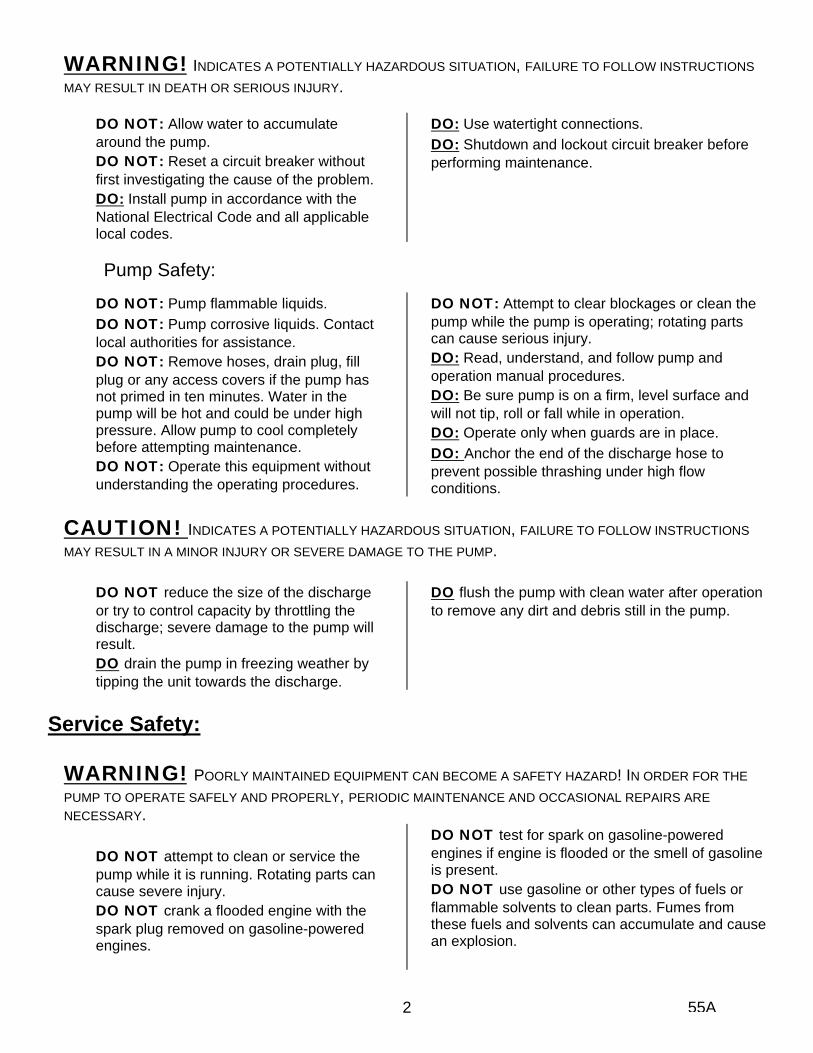
WARNING! INDICATES A POTENTIALLY HAZARDOUS SITUATION, FAILURE TO FOLLOW INSTRUCTIONS
MAY RESULT IN DEATH OR SERIOUS INJURY.
DO NOT: Allow water to accumulate around the pump. DO NOT: Reset a circuit breaker without first investigating the cause of the problem. DO: Install pump in accordance with the National Electrical Code and all applicable local codes.
DO: Use watertight connections. DO: Shutdown and lockout circuit breaker before performing maintenance.
Pump Safety:
DO NOT: Pump flammable liquids. DO NOT: Pump corrosive liquids. Contact local authorities for assistance. DO NOT: Remove hoses, drain plug, fill plug or any access covers if the pump has not primed in ten minutes. Water in the pump will be hot and could be under high pressure. Allow pump to cool completely before attempting maintenance. DO NOT: Operate this equipment without understanding the operating procedures.
DO NOT: Attempt to clear blockages or clean the pump while the pump is operating; rotating parts can cause serious injury. DO: Read, understand, and follow pump and operation manual procedures. DO: Be sure pump is on a firm, level surface and will not tip, roll or fall while in operation. DO: Operate only when guards are in place. DO: Anchor the end of the discharge hose to prevent possible thrashing under high flow conditions.
CAUTION! INDICATES A POTENTIALLY HAZARDOUS SITUATION, FAILURE TO FOLLOW INSTRUCTIONS
MAY RESULT IN A MINOR INJURY OR SEVERE DAMAGE TO THE PUMP.
DO NOT reduce the size of the discharge or try to control capacity by throttling the discharge; severe damage to the pump will result. DO drain the pump in freezing weather by tipping the unit towards the discharge.
DO flush the pump with clean water after operation to remove any dirt and debris still in the pump.
Service Safety:
WARNING! POORLY MAINTAINED EQUIPMENT CAN BECOME A SAFETY HAZARD! IN ORDER FOR THE
PUMP TO OPERATE SAFELY AND PROPERLY, PERIODIC MAINTENANCE AND OCCASIONAL REPAIRS ARE NECESSARY.
DO NOT attempt to clean or service the pump while it is running. Rotating parts can cause severe injury. DO NOT crank a flooded engine with the spark plug removed on gasoline-powered engines.
DO NOT test for spark on gasoline-powered engines if engine is flooded or the smell of gasoline is present. DO NOT use gasoline or other types of fuels or flammable solvents to clean parts. Fumes from these fuels and solvents can accumulate and cause an explosion.
2 55A
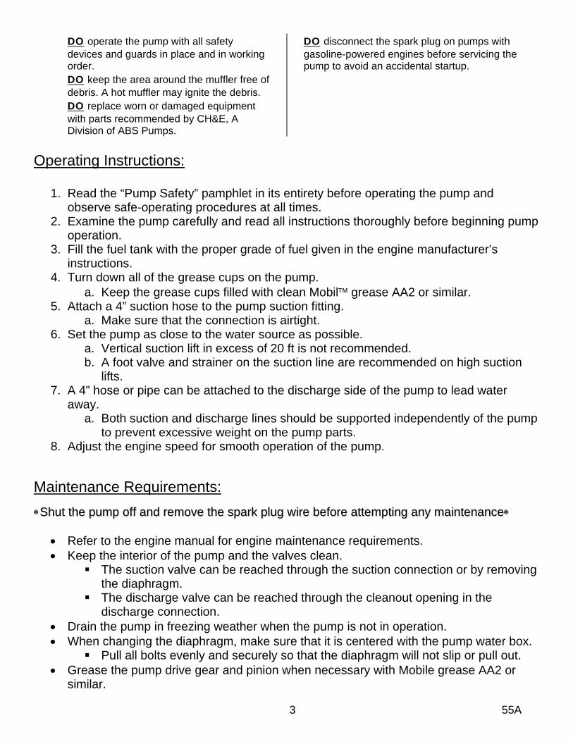
DO operate the pump with all safety devices and guards in place and in working order. DO keep the area around the muffler free of debris. A hot muffler may ignite the debris. DO replace worn or damaged equipment with parts recommended by CH&E, A Division of ABS Pumps.
DO disconnect the spark plug on pumps with gasoline-powered engines before servicing the pump to avoid an accidental startup.
Operating Instructions:
1. Read the “Pump Safety” pamphlet in its entirety before operating the pump and observe safe-operating procedures at all times.
2. Examine the pump carefully and read all instructions thoroughly before beginning pump operation.
3. Fill the fuel tank with the proper grade of fuel given in the engine manufacturer’s instructions.
4. Turn down all of the grease cups on the pump. a. Keep the grease cups filled with clean Mobil™ grease AA2 or similar.
5. Attach a 4” suction hose to the pump suction fitting. a. Make sure that the connection is airtight.
6. Set the pump as close to the water source as possible. a. Vertical suction lift in excess of 20 ft is not recommended. b. A foot valve and strainer on the suction line are recommended on high suction
lifts. 7. A 4” hose or pipe can be attached to the discharge side of the pump to lead water
away. a. Both suction and discharge lines should be supported independently of the pump
to prevent excessive weight on the pump parts. 8. Adjust the engine speed for smooth operation of the pump.
Maintenance Requirements:
∗∗SShhuutt tthhee ppuummpp ooffff aanndd rreemmoovvee tthhee ssppaarrkk pplluugg wwiirree bbeeffoorree aatttteemmppttiinngg aannyy mmaaiinntteennaannccee∗∗
• Refer to the engine manual for engine maintenance requirements. • Keep the interior of the pump and the valves clean.
The suction valve can be reached through the suction connection or by removing the diaphragm. The discharge valve can be reached through the cleanout opening in the
discharge connection. • Drain the pump in freezing weather when the pump is not in operation. • When changing the diaphragm, make sure that it is centered with the pump water box.
Pull all bolts evenly and securely so that the diaphragm will not slip or pull out. • Grease the pump drive gear and pinion when necessary with Mobile grease AA2 or
similar.
3 55A
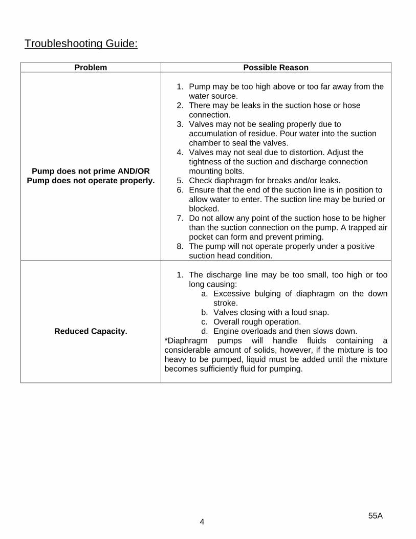
Troubleshooting Guide:
Problem Possible Reason
Pump does not prime AND/OR Pump does not operate properly.
1. Pump may be too high above or too far away from the
water source. 2. There may be leaks in the suction hose or hose
connection. 3. Valves may not be sealing properly due to
accumulation of residue. Pour water into the suction chamber to seal the valves.
4. Valves may not seal due to distortion. Adjust the tightness of the suction and discharge connection mounting bolts.
5. Check diaphragm for breaks and/or leaks. 6. Ensure that the end of the suction line is in position to
allow water to enter. The suction line may be buried or blocked.
7. Do not allow any point of the suction hose to be higher than the suction connection on the pump. A trapped air pocket can form and prevent priming.
8. The pump will not operate properly under a positive suction head condition.
Reduced Capacity.
1. The discharge line may be too small, too high or too
long causing: a. Excessive bulging of diaphragm on the down
stroke. b. Valves closing with a loud snap. c. Overall rough operation. d. Engine overloads and then slows down.
*Diaphragm pumps will handle fluids containing a considerable amount of solids, however, if the mixture is too heavy to be pumped, liquid must be added until the mixture becomes sufficiently fluid for pumping.
55A 4

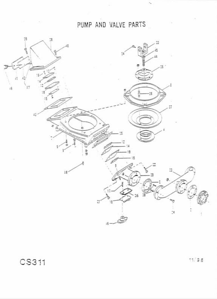
55A Parts
Ref. No.
Part No. Description Qty.
1 P0807 4” Cast Iron Flange 1 2 P1106 Flange Gasket 3 3 Hex Screws, 5/8” x 2 ¾” HN 5 4 P1157 Diaphragm Bottom 2 5 P1158 Diaphragm Clamp Ring 2 6 Hex Screws, 5/8” x 2 ½” HN 8 7 P1162 Water Box 2 8 Hex Screws, 5/8” x 3” HN, LW 8 9 ¼” Pipe Plug 2 10 P5436 Hand hole Cover 2 11 12 Flap Valve Assembly 2 13 Hex Screws, 3/8” x 1 ¼” 8 14 15 16 Carriage Bolt, 5/16” x 1 ¼” HN, LW 8 17 P5512 Stud, ½”‐13 x 1 ¾” 8 18 3/8” Pipe Plug 2 19 20 P1198 Suction Valve Connection 2 21 Hex Screws, 5/8” x 1 ¼” 4 22 Hex Screws, 5/8” x 3 ½” HN 4 23 P1200 Suction Manifold 1 24 Hex Screws, 5/8” x 2 ¼” HN 6 25 P1219 Suction Valve Connection Gasket 2 26 P5437 Hand hole Cover Gasket 2 27 28 29 30 P1236 Manifold Stud 5/8” HN 4 31 32 33 P1855 Connecting Rod Fork 2 34 Sq. Head Screw ¼”x ½” 2 35 P1874 Diaphragm Top 2 36 P3844 Stud, 5/8”‐11 x 2 ¾”, Heavy HN 4 37 P2157 Diaphragm 2 38 P5374 Discharge Spout w/ Cleanout 2 39 Hex Screws, 5/8”x 3 ¼” HN 4 40 Hex Screws, 5/8”x2” HN 4 41 P5375 Discharge Spout Cleanout Cover 2 42 P5376 Discharge Spout Cleanout Gasket 2 43 P2197 Discharge Spout Gasket 2 44 P2504 Diaphragm Top Stud 2 45 Lock Washer 1” 2 46 P3496E Clamp Handle 8

P0680E 14 Tooth Pinion (55A20‐Petter AB1; 55A30‐ Hatz E673; 55A40‐ Lombardini 6LD‐360; 55A130‐ Lister LV1)
1
P2170 18 Tooth Pinion (55AH‐B&S 233451; 55A50‐B&S 221457; 55A80‐Wis‐Robin WRD1‐270; 55A110‐B&S 190452; 55A120‐B&S 161452)
1
P2170A 18 Tooth Pinion (55A10‐Wisconsin S‐12D) 1
P2507 16 Tooth Pinion (55ATE Wisconsin TJD) 1
47
P0680X 14 Tooth Pinion (55ACE3; 55ACE5) 1 Key‐Gib Head ¼” sq. x 2” long 1 48 Key‐Gib Head 3/8” sq. x 2 ½” long 1
49 P1173 Lever Pin 3 50 P1850 Walking Beam Assembly w/ Bushings 1 51 P1851 Walking Beam Bracket 1 52 Sq. Head Setscrews 3/8” x 1 ¼” 2 53 P1852 Bearing Stand 1 54 P1853 120 Tooth Gear 1 55 Key‐Gib Head 3/8”x3/8”x2 ½” 1 56 P1854 Connecting Rod End 1 57 P1855 Connecting Rod Fork 1 58 Sq. Head Setscrew 3/8”x1” 1 59 P1856A Crank Pin Hub w/ Dowel Pin 1 60 P3698 Needle Bearing Assembly 1 61 Gib Head Key 3/8”x3/8”x2 ¼” 1 62 Sq. Head Setscrew ½”x1 ¼” (in P1856) 63 P1857 Crank Pin Washer 1 64 Hex Screw 5/8”x1 ½” LW 1 65 P1858 Bronze Bushing, 1 ¼” ID 3 66 P1859 Bronze Bushing 1 ½” ID 2 67 P1860 Side Crankshaft 1 68 P3699 Needle Bearing Assembly 2 69 P1861 Walking Beam Pivot 1 70 P1862 Connecting Rod 1 71 1” Jam Nut 2 72 P1868 Gear Guard 1 73 P1869 Gear Guard Support 2 74 Hex Screws, 3/8”x1” HN, LW 2 75 Rd. Head Stove Bolt ¼”x5/8” HN, LW 4 76 No.1 Grease Cup 6 77 90 St. Ell. 1