operating and installation instructions ventilation hood · operating and installation instructions...
TRANSCRIPT
Operating and Installation InstructionsVentilation Hood
To prevent accidents and damage to the appliance, you must readthese instructions before installing the appliance and using it for the firsttime.
en-US M.-Nr. 09 805 900

Contents
2
IMPORTANT SAFETY INSTRUCTIONS ................................................................. 4
Caring for the environment ................................................................................. 13
Description of functions ...................................................................................... 14Con@ctivity 2.0 function ........................................................................................ 15
Guide to the appliance......................................................................................... 16
Operation (Automatic mode)............................................................................... 18Cooking with Con@ctivity 2.0 (Automatic mode)................................................... 18Temporarily exiting Automatic mode ..................................................................... 20Resuming Automatic mode ................................................................................... 20
Operation (Manual mode).................................................................................... 21Cooking without Con@ctivity 2.0 (Manual mode) .................................................. 21Turning on the fan .................................................................................................. 21Selecting the power level....................................................................................... 21Selecting the delayed shut down time................................................................... 21Turning off the fan .................................................................................................. 21Turning overhead lighting on/off ............................................................................ 22Power management ............................................................................................... 22
Operation (Automatic and Manual modes)........................................................ 23Filter saturation indicator ....................................................................................... 23
Adjusting the filter saturation indicator for the grease filter .............................. 23Activating/changing the OdorFree Charcoal Filter operating hours counter .... 24Checking the filter saturation indicator ............................................................. 24
Sensor button signal tone...................................................................................... 25
Cleaning and care ................................................................................................ 26Stainless steel housing .......................................................................................... 26
Special instructions for glass surfaces ............................................................. 26Grease filters .......................................................................................................... 27OdorFree Charcoal Filter........................................................................................ 29
Resetting the operating hours counter for the OdorFree Charcoal Filter.......... 29Disposing of the OdorFree Charcoal Filter........................................................ 29
Service and warranty ........................................................................................... 30Location of the data plate ...................................................................................... 30
Installation ............................................................................................................ 31Before installation .................................................................................................. 31Removing the protective film ................................................................................. 31Installation Instructions .......................................................................................... 31
Contents
3
Disassembly........................................................................................................... 31Installation parts..................................................................................................... 32Appliance dimensions............................................................................................ 34Distance between cooktop and ventilation hood (S) ............................................. 35Installation recommendations................................................................................ 36Drilling diagram for wall mounting ......................................................................... 36Plywood backing .................................................................................................. 37To install a plywood backing ................................................................................. 37
Exhaust duct......................................................................................................... 38Condensate trap .................................................................................................... 39Reducing Collar .................................................................................................... 39
Electrical connection ........................................................................................... 40
Activating Con@ctivity 2.0 ................................................................................... 41Installation of the Con@ctivity 2.0 stick ................................................................. 41Activating the Con@ctivity 2.0 function ................................................................. 41
Activating the ventilation hood ......................................................................... 41Activating the cooktop...................................................................................... 42Activation failed ................................................................................................ 42
Deactivating Con@ctivity 2.0 ................................................................................. 42
Technical data ..................................................................................................... 43
IMPORTANT SAFETY INSTRUCTIONS
4
READ AND SAVE THESE INSTRUCTIONS
This appliance complies with current safety requirements.Improper use of the appliance can lead to personal injury andmaterial damage.
Read all instructions before installing or using the appliance forthe first time. Only use the appliance for its intended purpose.
Keep these operating instructions in a safe place and pass themon to any future user.
Use
CAUTION: For General Ventilating Use Only. Do Not Use ToExhaust Hazardous Or Explosive Materials And Vapors.
This appliance is intended for residential use only. Use only asdescribed in these operating instructions.
This ventilation hood is not intended for outdoor use.
It must only be used to extract and clean vapors produced duringcooking. Any other use occurs at the owner's own risk.
This appliance is suitable for installation above gas or electriccooking surfaces.
Persons who lack physical, sensory or mental abilities, orexperience with the appliance should not use it without supervisionor instruction by a responsible person.

IMPORTANT SAFETY INSTRUCTIONS
5
Children
As with any appliance, close supervision is necessary when usedby children.
Please supervise children in the vicinity of the hood and do not letthem play with it.
Danger of suffocation! Ensure that any plastic wrappings, bags,etc. are disposed of safely and kept out of the reach of children.
Technical safety
WARNING: TO REDUCE THE RISK OF FIRE, ELECTRIC SHOCK,OR INJURY TO PERSONS, OBSERVE THE FOLLOWING:
– Use this appliance only in the manner intended by themanufacturer. If you have questions, contact Miele.
– Before servicing or cleaning the appliance, switch power off atthe service panel and lock the service disconnecting means toprevent power from being switched on accidentally. If the servicedisconnecting means cannot be locked, securely fasten aprominent warning device, such as a tag, to the service panel.
Installation, repair and maintenance work should be performed bya Miele authorized service technician in accordance with nationaland local safety regulations and the provided installationinstructions. Contact Miele’s Technical Service Department forexamination, repair or adjustment. Repairs and other work byunauthorized persons could be dangerous and may void thewarranty.
A damaged ventilation hood oven can be dangerous. Alwayscheck for visible signs of damage. Never use a damaged ventilationhood.
IMPORTANT SAFETY INSTRUCTIONS
6
Be certain your appliance is properly installed and grounded by aqualified technician. To guarantee the electrical safety of thisappliance, continuity must exist between the appliance and aneffective grounding system. It is imperative that this basic safetyrequirement be met. If there is any doubt, have the electrical systemof the house checked by a qualified electrician.
To avoid damaging the ventilation hood, make sure that theconnection data (voltage and frequency) on the data platecorrespond to the building's power supply before connecting theappliance. When in doubt, consult a qualified electrician.
Do not use a power bar or extension cord to connect theventilation hood to electricity. These are a fire hazard and do notguarantee the required level of appliance safety.
To ensure safe operation, only use the ventilation hood after it hasbeen properly installed.
This ventilation hood may not be used in non-stationary locations(e.g. on a ship).
Only open the housing as described in the enclosed "Installationdiagram" and in the "Cleaning and care" section of this manual.Under no circumstances should any other parts of the housing beopened.Tampering with electrical connections or components andmechanical parts is highly dangerous to the user and can causeoperation faults.
IMPORTANT SAFETY INSTRUCTIONS
7
Defective components should be replaced by Miele original partsonly. Only with these parts can the manufacturer guarantee thesafety of the appliance.
If the power cord is damaged, it must only be replaced by aqualified service technician.
During installation, maintenance, and repair work, the ventilationhood must be disconnected from the electrical supply. It is onlycompletely isolated from the electricity supply if one of the followingapplies:
– The circuit breakers on the electrical service panel are tripped.
– The screw-type fuses on the electrical service panel have beenremoved.
– The power cable (if present) has been unplugged from the socket(pull the plug not the cord).
Proper use
WARNING: TO REDUCE THE RISK OF A COOKTOP GREASEFIRE:
– a) Never leave surface units unattended at high settings.Boilovers cause smoking and greasy spillovers may ignite. Heatoils slowly on low or medium settings.
– b) Always turn the hood on when cooking at a high heat.
– c) Clean the ventilation hood frequently. Grease should not beallowed to accumulate on the fan or filter.
– d) Use the proper pan size. Always use cookware appropriate forthe size of the cooking area.
Never use an open flame beneath the ventilation hood.To avoid the risk of fire, do not flambé or grill over an open flame.When turned on, the ventilation hood will draw any flames into thefilter. Fat deposits may ignite.

IMPORTANT SAFETY INSTRUCTIONS
8
WARNING: TO REDUCE THE RISK OF INJURY TO PERSONS INTHE EVENT OF A COOKTOP GREASE FIRE, OBSERVE THEFOLLOWING*:
– a) SMOTHER FLAMES with a close fitting lid, cookie sheet, ormetal tray then turn off the burner. BE CAREFUL TO PREVENTBURNS. If the flames do not go out immediately, EVACUATE ANDCALL THE FIRE DEPARTMENT.
– b) NEVER PICK UP A FLAMING PAN - You may be burned.
– c) DO NOT USE WATER, including wet dishcloths or towels - aviolent steam explosion will result.
– d) Use a fire extinguisher ONLY if:– 1) You have a class ABC extinguisher, and you know how to operate it.
– 2) The fire is small and contained in the area where it started.
– 3) The fire department is being called.
– 4) You can fight the fire with your back to an exit.
*Based on "Kitchen Firesafety Tips" published by NFPA.
The ventilation hood may become damaged if exposed toexcessive heat from a gas cooktop.
– When using the ventilation hood over a gas cooktop, ensure thatany burners in use are always covered by cookware. Turn burnersoff when removing the cookware, even if doing so for just a shorttime.
– Select cookware that is suitable for the size of the burner.
– Adjust the flame so that it never extends up the sides of thecookware.
– Avoid overheating the cookware (e.g., when cooking with a wok).
Always turn the ventilation hood on whenever a burner is in use toprevent damage from condensation.
IMPORTANT SAFETY INSTRUCTIONS
9
Overheated oils and fats can ignite and set the ventilation hoodon fire.When cooking with oils or fats, do not leave pots, pans or fryersunattended. Never leave an electric grill unattended when grilling.
Fat and debris deposits impair the proper functioning of theventilation hood.To ensure that cooking vapors are properly cleaned, never use theventilation hood without the grease filters in place.
A filter containing too much grease is a fire hazard!The filters should be cleaned or replaced at regular intervals.
Please note that the heat rising from the stovetop during cookingcan cause the ventilation hood to become very hot.Do not touch the housing or the grease filters until the ventilationhood has cooled down.
IMPORTANT SAFETY INSTRUCTIONS
10
Proper installation
WARNING: TO REDUCE THE RISK OF FIRE, ELECTRIC SHOCK,OR INJURY TO PERSONS, OBSERVE THE FOLLOWING:
– a) Installation work and electrical wiring must be done byqualified person(s) in accordance with all applicable codes andstandards, including fire-rated construction.
– b) Sufficient air is needed for combustion and exhausting ofgases through the flue (chimney of fuel burning equipment toprevent back drafting. Follow the heating equipmentmanufacturer’s guideline and safety standards such as thosepublished by the National Fire Protection Association (NFPA) andthe American Society for Heating, Refrigeration and AirConditioning Engineers (ASHRAE), and the local code authorities.
– c) When cutting or drilling into the wall or ceiling, do not damageelectrical wiring and other hidden utilities.
– d) Ducted hoods must always be vented to the outdoors.
– e) Do not use this hood with any solid-state speed control device.
To determine whether a ventilation hood may be operated aboveyour cooking appliance, please refer to the information provided bythe appliance's manufacturer.
Safety regulations prohibit the installation of a ventilation hoodabove solid fuel stoves.
Insufficient distance between the cooking appliance and theventilation hood can result in damage to the hood.The minimum safety distances between the appliance and thebottom of the ventilation hood specified in the "Installation" sectionmust be maintained, unless the appliance's manufacturer hasindicated that a greater distance is required.If more than one cooking appliance is used beneath the ventilationhood, and if different minimum safety distances apply for theseappliances, you should use the greater distance.

IMPORTANT SAFETY INSTRUCTIONS
11
Be sure to observe the information contained in the "Installation"section when mounting the ventilation hood.
When installing the exhaust duct, only use pipes or tubes made ofnon-flammable material. These can be obtained from your Mieledealer or from Miele Technical Service.
Exhaust air should not be vented into a chimney or vent fluewhich is otherwise in use and should not be channeled into ductingwhich ventilates rooms with fuel-burning installations.
If exhaust air is to be extracted into a chimney or vent flue nolonger used for other purposes, be sure to comply with all applicableregulations.
WARNING: TO REDUCE THE RISK OF FIRE USE ONLY METALDUCTWORK.
IMPORTANT SAFETY INSTRUCTIONS
12
Cleaning and care
Never use a steam cleaner to clean the ventilation hood.The steam can reach the electrical components and cause a shortcircuit.
Accessories
Use only genuine original Miele parts. If parts or accessories fromother manufacturers are used, the warranty will become void.
FCC Declaration of Conformity
These devices comply with FCC Rules Part 15. This equipmenthas been tested and found to be in compliance with the limits for aClass B digital device, pursuant to Part 15 of the FCC Rules ofOperation and is subject to the following conditions:These devices may not cause harmful interference.These devices must accept any interference received, includinginterference that may cause undesired operation.
FCC Radiation Exposure Statement
This equipment complies with FCC radiation exposure limits setforth for an uncontrolled environment. This equipment should beinstalled and operated with minimum distance 8" (20 cm) betweenthe radiator and your body.
Industry Canada Statement
This digital apparatus does not exceed the Class B limits forRadio Noise Emissions from digital apparatus set out in the RadioInterference Regulations of the Canadian Department ofCommunications.
Complies with Canadian ICES-003 Class B specifications.

Caring for the environment
13
Disposal of the packingmaterialThe cardboard box and packingmaterials protect the appliance duringshipping. They have been designed tobe biodegradable and recyclable.
Ensure that any plastic wrappings,bags, etc. are disposed of safely andkept out of the reach of children.Danger of suffocation!
Disposal of your old applianceDo not dispose of this appliance withyour household waste.
Old appliances may contain materialsthat can be recycled. Please contactyour local recycling authority about thepossibility of recycling these materials.
Before discarding an old applianceensure that it presents no danger tochildren while being stored for disposal.Unplug it from the outlet, cut off itspower cord and remove any doors toprevent hazards.
Description of functions
14
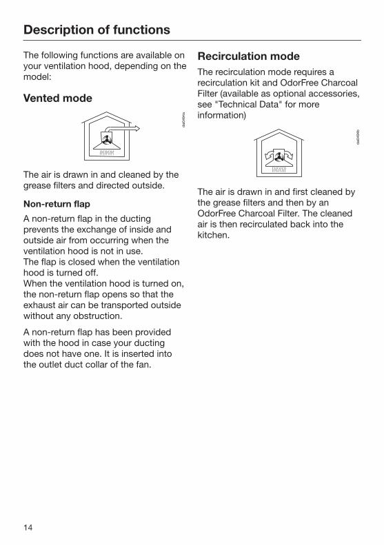
The following functions are available onyour ventilation hood, depending on themodel:
Vented mode
The air is drawn in and cleaned by thegrease filters and directed outside.
Non-return flap
A non-return flap in the ductingprevents the exchange of inside andoutside air from occurring when theventilation hood is not in use.The flap is closed when the ventilationhood is turned off.When the ventilation hood is turned on,the non-return flap opens so that theexhaust air can be transported outsidewithout any obstruction.
A non-return flap has been providedwith the hood in case your ductingdoes not have one. It is inserted intothe outlet duct collar of the fan.
Recirculation modeThe recirculation mode requires arecirculation kit and OdorFree CharcoalFilter (available as optional accessories,see "Technical Data" for moreinformation)
The air is drawn in and first cleaned bythe grease filters and then by anOdorFree Charcoal Filter. The cleanedair is then recirculated back into thekitchen.

Description of functions
15
Con@ctivity 2.0 functionAutomatic control
This hood features a communicationfunction which enables the automaticcontrol of the hood based on theoperational status of a Miele cooktop.
To enable the communication function,the cooktop must be equipped with thecorresponding Con@ctivity 2.0 stick .
Please refer to the installationinstructions for the Con@ctivity 2.0stick to determine whether connectionto your cooktop is possible.
There must be radio contact betweenthe cooktop and the hood for you to beable to use the Con@ctivity 2.0 function(see "Activating Con@ctivity 2.0").
The cooktop transmits informationabout its operational status to the hoodusing a radio signal.
– When a burner is turned on, thecooktop lighting on the hood turnson automatically. After a brief delay,the ventilation hood fan also comeson.
– During cooking, the hoodautomatically selects the fan levelbased on the number of burners inoperation and their power levels.
– Once you have turned off thecooktop, the fan and the lighting willturn off automatically after apredetermined delay.
Detailed information about this functioncan be found under "Operation."
Guide to the appliance
16

Guide to the appliance
17
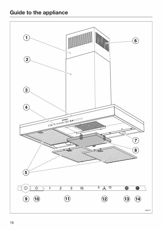
a Telescopic chimney
b Chimney
c Canopy
d Control panel
e Grease filters
f Recirculation vent(only for recirculation mode)
g LED cooktop lighting
h OdorFree Charcoal FilterOptional accessory for recirculation mode
i Sensor button for turning the fan on and off
j Cooktop light sensor button
k Sensor buttons for fan power selection
l Sensor button for delayed shut-down function
m Filter saturation indicator for the grease filters
n Filter saturation indicator for the OdorFree Charcoal Filter
Operation (Automatic mode)
18
When Con@ctivity 2.0 is active, thehood always operates in Automaticmode (see "Activating [email protected]").
See "Cooking without Con@ctivity 2.0"for information on manually operatingthe hood.
Cooking with Con@ctivity 2.0(Automatic mode) Turn on a burner to the desired power
setting.
The hood lighting will come on.
After a few seconds, the fan will comeon, briefly operating at power level 2before immediately switching to level 1.
The hood selects the fan levelautomatically during cooking.
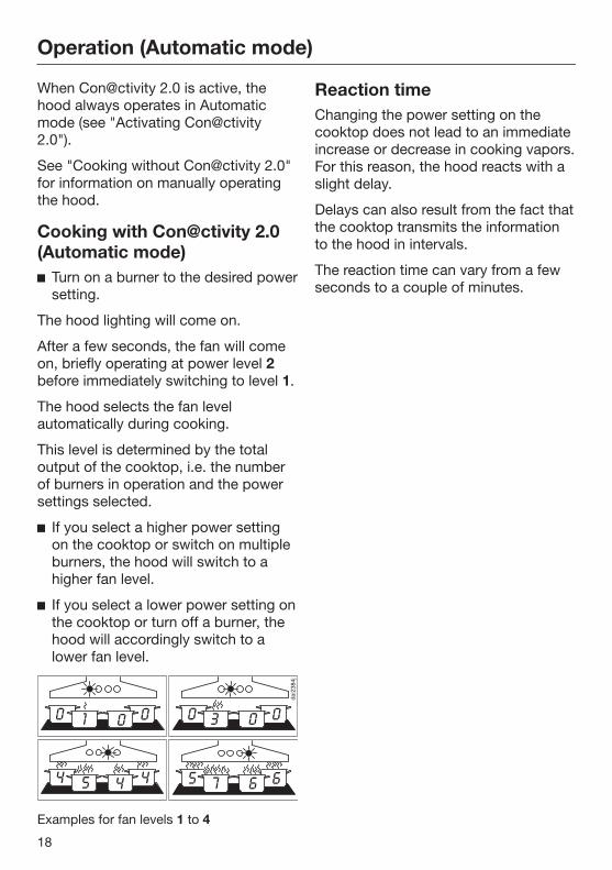
This level is determined by the totaloutput of the cooktop, i.e. the numberof burners in operation and the powersettings selected.
If you select a higher power settingon the cooktop or switch on multipleburners, the hood will switch to ahigher fan level.
If you select a lower power setting onthe cooktop or turn off a burner, thehood will accordingly switch to alower fan level.
Examples for fan levels 1 to 4
Reaction timeChanging the power setting on thecooktop does not lead to an immediateincrease or decrease in cooking vapors.For this reason, the hood reacts with aslight delay.
Delays can also result from the fact thatthe cooktop transmits the informationto the hood in intervals.
The reaction time can vary from a fewseconds to a couple of minutes.
Operation (Automatic mode)
19
Cooking process If, for example, you switch on a
burner at the highest power setting toheat cookware in preparation forsearing and then reduce the powerlevel after approx. 60 to 90 seconds*,a cooking process is recognized.
The hood turns on automatically and,after the cooktop power level has beenreduced, switches back to fan level 3,where it remains for approx. 5 minutes.
After this, the fan level is once againdetermined by the Con@ctivity function.
You can also manually select adifferent fan level before then.
Turning off Turn off all burners.
Over the next few minutes, theventilation hood fan setting willdecrease one level at a time until thehood eventually turns off.
This helps to neutralize any lingeringvapors and odors in the air.
– From the intensive setting IS, the fanimmediately switches to level 3.
– If the fan is operating at level 3, it willswitch to level 2 after approx. 1minute.
– From level 2, the fan switches to level1 after 2 minutes.
– After 2 minutes at level 1, the fanautomatically turns off.
– After another 30 seconds, the lightingturns off.
The cooking process is now finished.
Operation (Automatic mode)
20
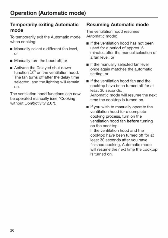
Temporarily exiting AutomaticmodeTo temporarily exit the Automatic modewhen cooking:
Manually select a different fan level,or
Manually turn the hood off, or
Activate the Delayed shut downfunction on the ventilation hood.The fan turns off after the delay timeselected, and the lighting will remainon.
The ventilation hood functions can nowbe operated manually (see "Cookingwithout Con@ctivity 2.0").
Resuming Automatic modeThe ventilation hood resumesAutomatic mode:
If the ventilation hood has not beenused for a period of approx. 5minutes after the manual selection ofa fan level, or
If the manually selected fan levelonce again matches the automaticsetting, or
If the ventilation hood fan and thecooktop have been turned off for atleast 30 seconds.Automatic mode will resume the nexttime the cooktop is turned on.
If you wish to manually operate theventilation hood for a completecooking process, turn on theventilation hood fan before turningon the cooktop.If the ventilation hood and thecooktop have been turned off for atleast 30 seconds after you havefinished cooking, Automatic modewill resume the next time the cooktopis turned on.
Operation (Manual mode)
21
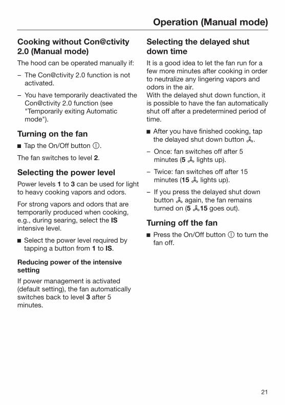
Cooking without [email protected] (Manual mode)The hood can be operated manually if:
– The Con@ctivity 2.0 function is notactivated.
– You have temporarily deactivated theCon@ctivity 2.0 function (see"Temporarily exiting Automaticmode").
Turning on the fan Tap the On/Off button .
The fan switches to level 2.
Selecting the power levelPower levels 1 to 3 can be used for lightto heavy cooking vapors and odors.
For strong vapors and odors that aretemporarily produced when cooking,e.g., during searing, select the ISintensive level.
Select the power level required bytapping a button from 1 to IS.
Reducing power of the intensivesetting
If power management is activated(default setting), the fan automaticallyswitches back to level 3 after 5minutes.
Selecting the delayed shutdown timeIt is a good idea to let the fan run for afew more minutes after cooking in orderto neutralize any lingering vapors andodors in the air.With the delayed shut down function, itis possible to have the fan automaticallyshut off after a predetermined period oftime.
After you have finished cooking, tapthe delayed shut down button .
– Once: fan switches off after 5minutes (5 lights up).
– Twice: fan switches off after 15minutes (15 lights up).
– If you press the delayed shut downbutton again, the fan remainsturned on (5 15 goes out).
Turning off the fan Press the On/Off button to turn the
fan off.

Operation (Manual mode)
22
Turning overhead lightingon/offThe overhead lighting can be turned onand off separately from the fan.
Tap the lighting button .
Power managementThe ventilation hood features a powermanagement system for switching offthe lighting and reducing the fan powersetting automatically.
– If the intensive setting is selected, thefan automatically switches to level 3after 5 minutes.
– If the fan is set to level 3, 2 or 1, itswitches to the next-highest fansetting after 2 hours and then in 30-minute intervals until the faneventually switches off.
– If the cooktop lighting is on, itautomatically turns off after 12 hours.
Turning power management on/off
Turn off the fan and the lighting.
Press the delayed shut down button for approx. 10 seconds until 1lights up in the fan power display.
Next, tap the following buttons insuccession:
– The lighting button ,
– Followed by the 1 button and then
– The lighting button again.
If power management is turned on, the1 and IS indicators will be continuouslylit.If it is switched off, 1 and IS will flash.
Tap 1 to turn off the powermanagement.
The 1 and IS indicators will flash.
Touch IS to turn it on.
The 1 and IS indicators are constantlylit.
Confirm the setting by pressing thedelayed shut down button .
All the indicator lights will go out.
If the setting is not confirmed within 4minutes, the hood automatically revertsto the old setting.

Operation (Automatic and Manual modes)
23
Filter saturation indicatorThe number of hours the hood hasbeen in operation is stored in appliancememory.
The filter saturation indicators showwhen the filters need to be cleaned orchanged by lighting up the grease filtersymbol or OdorFree Charcoal Filtersymbol . Additional information oncleaning and changing the filters andresetting the filter saturation counterscan be found under "Cleaning andcare."
Adjusting the filter saturationindicator for the grease filter
You can set the filter saturationindicator to suit your cooking habits.
The factory default setting is a cleaninginterval of 30 hours.
– Select a shorter time (20 hours) if youoften fry foods.
– We also recommend a shortercleaning interval if you only cookoccasionally. This will prevent greasebuildup from hardening and makingcleaning more difficult.
– Select a longer cleaning interval of 40or 50 hours if you use very little fatwhen cooking.
Press the On/Off button to turn offthe fan.
Tap the delayed shut down button and the grease filter button at thesame time.
The grease filter symbol and one ofthe fan power level indicators will flash.
The indicators 1 to IS show the currenttime setting:
Indicator 1 ............................... 20 hours
Indicator 2................................ 30 hours
Indicator 3................................ 40 hours
Indicator IS .............................. 50 hours
Tap the relevant button to select thetime required.
Confirm your choice by touching thegrease filter button .
All the indicator lights will go out.
If the setting is not confirmed within 4minutes, the hood automatically revertsto the old setting.
Operation (Automatic and Manual modes)
24
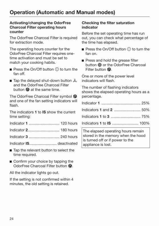
Activating/changing the OdorFreeCharcoal Filter operating hourscounter
The OdorFree Charcoal Filter is requiredfor extraction mode.
The operating hours counter for theOdorFree Charcoal Filter requires one-time activation and must be set tomatch your cooking habits.
Press the On/Off button to turn thefan off.
Tap the delayed shut-down button and the OdorFree Charcoal Filterbutton at the same time.
The OdorFree Charcoal Filter symbol and one of the fan setting indicators willflash.
The indicators 1 to IS show the currenttime setting:
Indicator 1 ............................. 120 hours
Indicator 2.............................. 180 hours
Indicator 3 ............................. 240 hours
Indicator IS.......................... deactivated
Tap the relevant button to select thetime required.
Confirm your choice by tapping theOdorFree Charcoal Filter button .
All the indicator lights go out.
If the setting is not confirmed within 4minutes, the old setting is retained.
Checking the filter saturationindicator
Before the set operating time has runout, you can check what percentage ofthe time has elapsed.
Press the On/Off button to turn thefan on.
Press and hold the grease filterbutton or the OdorFree CharcoalFilter button .
One or more of the power levelindicators will flash.
The number of flashing indicatorsshows the elapsed operating hours as apercentage.
Indicator 1 ..................................... 25%
Indicators 1 and 2 ......................... 50%
Indicators 1 to 3 ............................ 75%
Indicators 1 to IS ......................... 100%
The elapsed operating hours remainstored in the memory when the hoodis turned off or if power to theappliance is lost.
Operation (Automatic and Manual modes)
25
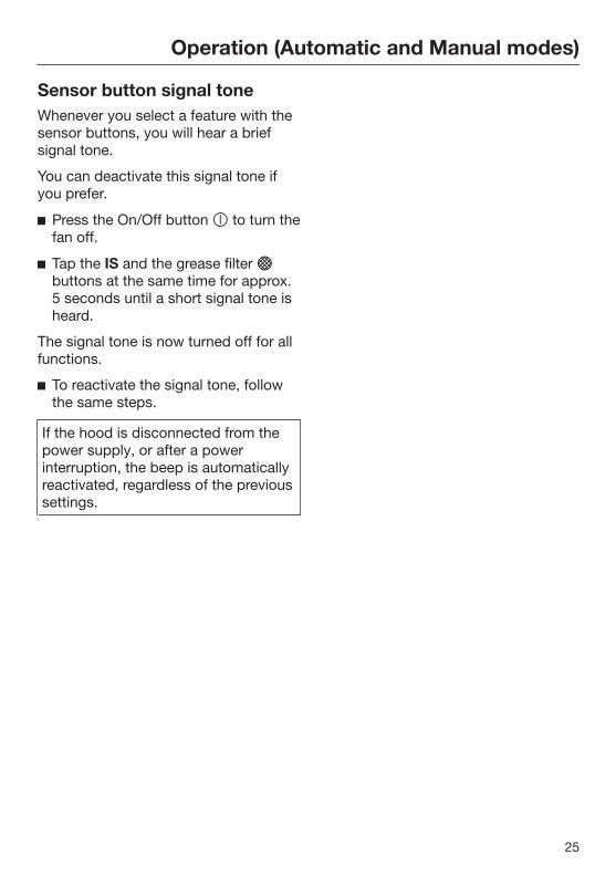
Sensor button signal toneWhenever you select a feature with thesensor buttons, you will hear a briefsignal tone.
You can deactivate this signal tone ifyou prefer.
Press the On/Off button to turn thefan off.
Tap the IS and the grease filter buttons at the same time for approx.5 seconds until a short signal tone isheard.
The signal tone is now turned off for allfunctions.
To reactivate the signal tone, followthe same steps.
If the hood is disconnected from thepower supply, or after a powerinterruption, the beep is automaticallyreactivated, regardless of the previoussettings.
Cleaning and care
26
WARNING: TO REDUCE THE RISKOF FIRE, ELECTRIC SHOCK, ORINJURY TO PERSONS, OBSERVETHE FOLLOWING:
Before cleaning or servicing thehood, disconnect it from the powersupply, see "IMPORTANT SAFETYINSTRUCTIONS".
Stainless steel housing
General information
The surfaces and control buttons aresusceptible to scratching andchipping.Observe the following cleaninginstructions.
Clean all surfaces and controlbuttons using warm water and liquiddish soap. Apply with a sponge cloth.
After cleaning, dry the surfaces with asoft cloth.
Avoid the following:
– Cleaners containing soda, acid orchloride, or cleaners containingsolvents
– Abrasive cleaners such as scouringpowder, scouring liquid, abrasivesponges such as pot scourers, orused sponges that still containresidues from abrasive cleaners
Special instructions for stainlesssteel surfaces
Stainless steel surfaces can also becleaned using a non-abrasivestainless steel cleaner.
To prevent the surfaces from quicklybecoming dirty again, werecommend treating them with astainless steel care conditioner.Apply sparingly over the entire areausing a soft cloth.
Special instructions for RAL colorfinish housing
(special order)
Observe the general cleaninginstructions contained in this chapter.
Minor scratches on the surface areinevitable when cleaning the housing.Depending on the lighting in thekitchen, this may negatively affect theappliance's appearance.
Special instructions for glasssurfaces
Glass surfaces can be cleaned usinga commercial glass cleaner.
Cleaning and care
27
Grease filtersThe reusable metal grease filters in theappliance remove the solid particlescontained in kitchen vapors (fat, dust,etc.), thereby preventing the ventilationhood from becoming dirty.
A dirty filter is a fire hazard!
Cleaning intervals
Over longer periods of time, fat buildupon the grease filter hardens and makescleaning more difficult. Therefore, werecommend cleaning the grease filtersonce every 3-4 weeks.
By illuminating the grease filter symbol,the filter saturation counter remindsyou to regularly clean the grease filters.
You can adjust the interval of the filtersaturation counter to match yourcooking habits (see "Operation").
Removing the grease filters
When handling a grease filter, becareful not to drop it.This can result in damage to the filterand to the cooktop.Make sure you hold the filtersecurely at all times when handlingit.
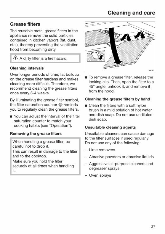
To remove a grease filter, release thelocking clip. Then, open the filter to a45° angle, unhook it, and remove itfrom the hood.
Cleaning the grease filters by hand
Clean the filters with a soft nylonbrush in a mild solution of hot waterand dish soap. Do not use undiluteddish soap.
Unsuitable cleaning agents
Unsuitable cleaners can cause damageto the filter surfaces if used regularly.Do not use any of the following:
– Lime removers
– Abrasive powders or abrasive liquids
– Aggressive all-purpose cleaners anddegreaser sprays
– Oven sprays

Cleaning and care
28
Cleaning the grease filters in thedishwasher
Place the filters as upright or inclinedas possible in the lower basket.Ensure that the spray arm is notobstructed.
Use a common householddishwasher detergent.
Select a program with a washtemperature between 122°F (50°C)and 149°F (65°C). In a Mieledishwasher use the "Normal"program.
Depending on the detergent used,cleaning the filters in a dishwashermay cause the inside filter surfaces tobecome discolored. However, this willnot affect the functioning of the filtersin any way.
After cleaning
After cleaning, leave the filters on anabsorbent surface to dry.
When removing the filters forcleaning, also clean off anyaccessible oil or fat buildup from thehousing. Doing so will prevent a firehazard.
Reinstall the grease filters. Wheninserting the filters, make sure thatthe locking clip is facing down.
If the filters have been installedincorrectly, you can insert a smallscrewdriver into the slit to disengagethe locking clip.
Resetting the filter saturationindicator for the grease filter
Once cleaning is complete, the filtersaturation indicator must be reset.
While the fan is turned on, press thegrease filter button for approx. 3seconds, until only the 1 is flashing.
The grease filter symbol goes out.
When cleaning the grease filters beforethe full operating time has elapsed:
Press the grease filter button forapprox. 6 seconds, until only the 1 isflashing.
Cleaning and care
29
OdorFree Charcoal FilterIf the hood is equipped for recirculation,an OdorFree Charcoal Filter must beinstalled in addition to the grease filters.This filter is designed to absorb odor-causing agents and is mounted in thecanopy above the grease filters.
OdorFree Charcoal Filters are availablefrom your Miele dealer or from Miele.See "Technical data" for the type andreference number.
Installing/replacing the OdorFreeCharcoal Filter
To install or replace the OdorFreeCharcoal Filter, the grease filters mustfirst be removed as described above.
Remove the charcoal filter from itspackaging.
Slide the OdorFree Charcoal Filterinto the back of the intake frame,then push the front of the filter up intothe frame.
Reinstall the grease filters.
When installing the filter for the firsttime, activate the filter saturationcounter (see "Operation").
When to change the OdorFreeCharcoal Filter
Always replace the OdorFreeCharcoal Filter whenever it no longerabsorbs kitchen odors effectively.Replace the filter at least once every6 months.
The OdorFree Charcoal Filter saturationcounter will light up to remind you tochange the charcoal filter regularly.
The OdorFree Charcoal Filtersaturation counter requires one-timeactivation before use (see the"Operation" chapter).
Resetting the operating hourscounter for the OdorFree CharcoalFilter
If the operating hours counter isactivated, it must be reset each timethe filter is changed.
Press the OdorFree Charcoal Filterbutton for approx. 3 seconds withthe ventilation hood switched on untilonly the indicator light for level 1 isflashing.
The OdorFree Charcoal Filter symbol will go out.
If you replace the OdorFree CharcoalFilter before the full operating timeelapses:
Press the OdorFree Charcoal Filterbutton for approx. 6 seconds untilonly the indicator light for level 1 isflashing.
Disposing of the OdorFree CharcoalFilter
Used OdorFree Charcoal Filters canbe disposed of with normalhousehold waste.

Service and warranty
30
For faults that you cannot resolve onyour own, please contact your Mieledealer or Miele Technical Service.
The telephone number for the TechnicalService Department is listed at the backof these instructions.
When contacting Miele, please statethe model and serial number of yourventilation hood.These can be found on the data plate.
Location of the data plateThe data plate is visible once you haveremoved the grease filters.
WarrantyFor further information, please refer toyour warranty booklet.
Installation
31
Before installation
Before installing the appliance,read all of the information containedin this chapter and also in the"IMPORTANT SAFETYINSTRUCTIONS" section.
Removing the protective filmThe housing components are coveredby a protective film to prevent themfrom becoming damaged duringtransport.
Please remove this film beforeinstalling the housing components. Itcan be peeled off easily without anyadditional tools.
Installation InstructionsPlease refer to the accompanyinginstallation sheet for instructions onhow to install the appliance.
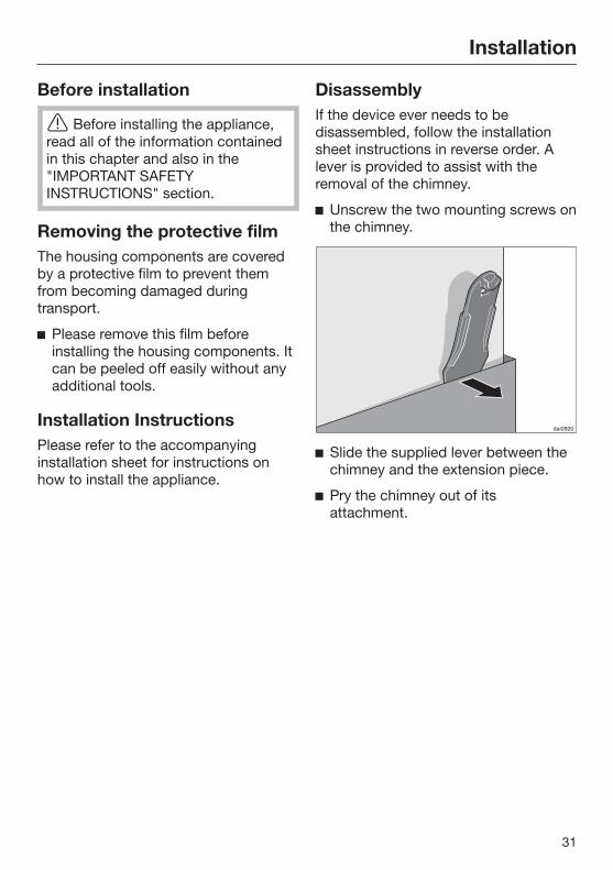
DisassemblyIf the device ever needs to bedisassembled, follow the installationsheet instructions in reverse order. Alever is provided to assist with theremoval of the chimney.
Unscrew the two mounting screws onthe chimney.
Slide the supplied lever between thechimney and the extension piece.
Pry the chimney out of itsattachment.
Installation
32
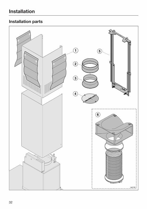
Installation parts

Installation
33
a 3 protective installation sheetsfor use when installing the chimney
b 1 exhaust connectorfor an exhaust duct 6" (150 mm).
c 1 reducerfor an exhaust duct 5" (125 mm).
d 1 non-return flapfor installation in the outlet ductcollar of the motor unit (not forrecirculation mode). Depending onthe device version, the non-returnflap is already mounted.
e Telescopic wall bracketfor securing the hood on the wall.
f Recirculation kit for recirculationmodecontains diverter, aluminum hoseand hose clamps (not contained inscope of delivery, available asoptional accessory – see "TechnicalData").
6 screws 1/2" x 2 3/8" (5 x 60 mm)and6 plugs 5/16" x 2" (8 x 50 mm)for attaching to the wall. Plugs not foruse in USA / CDN.
The screws and plugs are designedfor use in solid walls only.Use different fasteners for other wallconstruction types.Make sure that the wall can supportthe load.
2 x M 6 lock nutsfor mounting the appliance unit.
2 screws 1/8" x 5/16" (3.9 x 7.5 mm)for attaching the chimney.
1 leverfor disassembling the chimney.
Montage
Installation
Montaje
M
ontaggio
Montering
Montagem
A
sennus
Installation sheet

Installation
34
Appliance dimensions
The drawing is not to scale.
a Extraction
b Recirculation
Installation
35
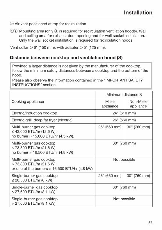
c Air vent positioned at top for recirculation
de Mounting area (only d is required for recirculation ventilation hoods). Walland ceiling area for exhaust duct opening and for wall socket installation.Only the wall socket installation is required for recirculation hoods.
Vent collar 6" (150 mm), with adapter 5" (125 mm).
Distance between cooktop and ventilation hood (S)
Provided a larger distance is not given by the manufacturer of the cooktop,follow the minimum safety distances between a cooktop and the bottom of thehood.Please also observe the information contained in the "IMPORTANT SAFETYINSTRUCTIONS" section.
Minimum distance S
Cooking appliance Mieleappliance
Non-Mieleappliance
Electric/Induction cooktop 24" (610 mm)
Electric grill, deep fat fryer (electric) 26" (660 mm)
Multi-burner gas cooktop ≤ 43,000 BTU/hr (12.6 W), no burner > 15,000 BTU/hr (4.5 kW).
26" (660 mm) 30" (760 mm)
Multi-burner gas cooktop ≤ 73,800 BTU/hr (21.6 W), no burner > 16,500 BTU/hr (4.8 kW)
30" (760 mm)
Multi-burner gas cooktop > 73,800 BTU/hr (21.6 W), or one of the burners > 16,500 BTU/hr (4.8 kW)
Not possible
Single-burner gas cooktop ≤ 20,500 BTU/hr (6 kW)
26" (660 mm) 30" (760 mm)
Single-burner gas cooktop ≤ 27,600 BTU/hr (8.1 kW)
30" (760 mm)
Single-burner gas cooktop > 27,600 BTU/hr (8.1 kW)
Not possible

Installation
36
Installation recommendations– We also recommend a distance of at
least 25 1/2" (650 mm) above electriccooktops to provide more workspaceand easier cooking under the hood.
– When selecting an installation height,always take the user height intoconsideration. Users should haveample space to work comfortably onthe cooktop and reach the ventilationhood controls with ease.
– Please note that the greater thedistance from the cooktop, the lesseffective the hood is at drawing in thecooking vapors.
– To achieve optimal vapor extraction,make sure that the hood covers thecooktop. The hood should bepositioned centrally over thecooktop, not to the side or rear.
– The cooktop should be no wider thanthe hood. Preferably, it should benarrower.
– The mounting area must be easilyaccessible. The ventilation hoodshould be easy to reach anddisassemble in case a service call isnecessary. This should be taken intoconsideration when planning theposition of cupboards, shelves,ceilings or decorative elements in thevicinity of the ventilation hood.
Drilling diagram for wallmounting When drilling, please follow the
directions contained on theaccompanying installation sheet.
dai3124us
When installing a custom back wallwith pre-drilled holes, please refer tothe drilling distances in the drawingabove (screws 3/16" (5 mm)).
Installation
37
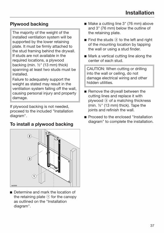
Plywood backing
The majority of the weight of theinstalled ventilation system will besupported by the lower retainingplate. It must be firmly attached tothe stud framing behind the drywall.If studs are not available in therequired locations, a plywoodbacking (min. ½" (13 mm) thick)spanning at least two studs must beinstalled.Failure to adequately support theweight as stated may result in theventilation system falling off the wall,causing personal injury and propertydamage.
If plywood backing is not needed,proceed to the included "Installationdiagram".
To install a plywood backing
Determine and mark the location ofthe retaining plate for the canopyas outlined on the "Installationdiagram".
Make a cutting line 3" (76 mm) aboveand 3" (76 mm) below the outline ofthe retaining plate.
Find the studs to the left and rightof the mounting location by tappingthe wall or using a stud finder.
Mark a vertical cutting line along thecenter of each stud.
CAUTION: When cutting or drillinginto the wall or ceiling, do notdamage electrical wiring and otherhidden utilities.
Remove the drywall between thecutting lines and replace it withplywood of a matching thickness(min. ½" (13 mm) thick). Tape thejoints and refinish the wall.
Proceed to the enclosed "Installationdiagram" to complete the installation.

Exhaust duct
38
WARNING: Danger of toxic fumes.Gas cooking appliances releasecarbon monoxide that can beharmful or fatal if inhaled.To reduce the risk of fire and toproperly exhaust air, the exhaustgases extracted by the hood shouldbe vented outside of the buildingonly.Do not vent exhaust air into spaceswithin walls or ceilings or in attics,crawl spaces or garages.To reduce the risk of fire, only usemetal ductwork.Please read and follow the"IMPORTANT SAFETYINSTRUCTIONS" to reduce the riskof personal injury. Follow all localbuilding codes when installing thehood.
Only use smooth pipes or flexibleduct hoses made from non-flammable materials for exhaustductwork.
To achieve the greatest possible airextraction with the lowest noiselevels, please note the following:
– The diameter of the exhaust ductshould not be less than 6" (150 mm).
– If flat exhaust ducts are used, thecross section should not be smallerthan that of the exhaust connector.
– The exhaust duct should be as shortand straight as possible.
– If elbows are needed, make sure theyhave a large radius.
– The exhaust duct itself must not bekinked or compressed.
– Make sure that all connections aresecure and airtight.
Remember that any constriction ofthe airflow will reduce extractionperformance and increase operatingnoise.
If the exhaust duct is to be routedthrough an outside wall, werecommend installing a telescopicwall vent or a rooftop vent (availableas an optional accessory).
If the exhaust air is to be conductedinto a vent flue, the intake piece mustbe aligned with the flow direction ofthe flue.
When installing the exhaust ducthorizontally, you must slope it awayfrom the source by at least 1 cm permeter (3/8" per 3 1/4'). This ensuresthat condensate cannot drain backinto the ventilation hood.
If the exhaust duct is to be routedthrough rooms, ceiling space etc., thetemperatures in these different areasmay differ greatly, which means thatthe problem of condensation willneed to be addressed. The exhaustduct will need to be insulated.

Exhaust duct
39
Condensate trap
In addition to insulating the exhaustduct, we recommend installing acondensate trap to collect andevaporate any condensate which mightaccumulate.Condensate traps are available forexhaust ducts with a diameter of 5"(125 mm) or 6" (150 mm).
When installing a condensate trap,make sure that it is positionedvertically and, if possible, directlyabove the hood outlet duct collar.The arrow on the housing indicatesthe direction of airflow.
Reducing Collar(optional accessory)
If you would like to reduce theenvironmental impact of your ventilationsystem by limiting the CFM output theReducing Collar can be installed. Itreduces the air flow to less than 400CFM. Check local building codes formax. CFM requirements.
Push the Reducing Collar on theexhaust port of the fan.
Push the exhaust hose over it.
Fix both with a hose clamp.

Electrical connection
40
WARNING: TO REDUCE THE RISKOF FIRE, ELECTRIC SHOCK, ORINJURY TO PERSONS, OBSERVETHE FOLLOWING:All electrical work should beperformed by a qualified electricianin strict accordance with nationalregulations (for USA: ANSI-NFPA 70)and local safety regulations.Installation, repairs and other workby unqualified persons could bedangerous.Ensure that power to the appliance isOFF while installation or repair workis performed.Verify that the voltage, load andcircuit rating information found onthe data plate (located behind thebaffle filters), match the householdelectrical supply before installing thehood.Use only with ventilation hood cord-connection kits that have beeninvestigated and found acceptablefor use with this model hood.If there is any question concerningthe electrical connection of thisappliance to your power supply,please consult a licensed electricianor call Miele’s Technical ServiceDepartment.
WARNING: THIS APPLIANCE MUSTBE GROUNDED
The hood comes equipped with apower cord with a NEMA 5-15 moldedplug for connection to a 120 VAC,60 Hz, 15 A power outlet.
Grounding Instructions
WARNING - Improper grounding canresult in a risk of electric shock.
This appliance must be grounded. Inthe event of an electrical short circuit,grounding reduces the risk of electricshock by providing a path of leastresistance. This appliance is equippedwith a cord having a grounding wirewith a grounding plug.
If there is any doubt, have the electricalsystem of the house checked by aqualified electrician.
Do not use an extension cord. If thepower supply cord is too short, have aqualified electrician install an outletnear the appliance.
The plug must be plugged into anoutlet that is properly installed andgrounded.
WARNING - Grounding instructions(Canada)The grounding-type attachment plugshall be connected to a grounding-type receptacle installed inaccordance with CSA C22.1-12,Canadian Electrical Code, Part I.

Activating Con@ctivity 2.0
41
Installation of the [email protected] stickIn order for you to be able to use theCon@ctivity 2.0 function, the cooktopmust be equipped with a [email protected] stick.
See the relevant installationinstructions of the Con@ctivity 2.0stick.
Activating the Con@ctivity 2.0functionTo use the Con@ctivity 2.0 function, theradio link between the cooktop and theventilation hood must be activated.
Both appliances must be installed andoperational.
Wireless connection must be activatedon the ventilation hood and the cooktopat the same time. Activation on theventilation hood is described below. Activation on the cooktop is describedin the relevant operating and installationinstructions. Please refer to theoperating instructions before starting.Activate the ventilation hood first, thenthe cooktop.
Activating the ventilation hood
The cooktop and hood must beturned off.
Press the delayed shut down button for approx. 10 seconds until 1lights up in the fan setting display.
Next, tap the following buttons insuccession:
– The 1 button,
– Then the IS button,
– And then the lighting button .
The hood is in log on / log off mode.
If the wireless connection is alreadyactivated, 2 and 3 will light up at thesame time. If there is no wireless connection, 2 and3 will flash constantly (Con@ctivity 2.0is already activated or a remote controlis logged on).
To activate Con@ctivity 2.0, tap theIS button.
The search for a wireless connectionwill start.
As this is happening, begin activationon the cooktop.

Activating Con@ctivity 2.0
42
Activating the cooktop
While the ventilation hood issearching for a wireless connection,start activation on the cooktop.More information can be found in theoperating instructions for thecooktop.
When the cooktop registers thatconnection has been established,confirm activation on the ventilationhood with the delayed shut-downbutton 515. All indicators will goout.
Confirm activation on the cooktop.
The Con@ctivity 2.0 function is nowready for use.
If you do not confirm within 4 minutes,activation will be canceled.
You only need to carry out theactivation procedure once. If theappliances are disconnected from theelectricity supply, for example duringa loss of power, they will still remainactivated.
Activation failed
If a wireless connection cannot beestablished despite activation of theCon@ctivity function on theventilation hood and cooktop, thefunction must first be deactivatedand then reactivated on bothappliances.
Deactivating Con@ctivity 2.0 Deactivation on the ventilation hood
is similar to the activation procedure.Select the IS instead of the 1 button.
To deactivate the cooktop, pleaserefer to the corresponding operatinginstructions.
Please keep in mind that disabling theconnection will also disable anyremote control function being used.The remote control must then bereactivated.

Technical data
43
Fan motor 350 W
LED cooktop lighting 3 x 3 W
Total connected load 359 W
Voltage, Frequency 120 V AC, 60 Hz
Fuse rating 15 A
Power cord length 2.5 ft. (0.75 m)
Weight 57.2 lbs (26 kg)
Optional accessories for recirculation mode:Recirculation kit DUW 20 and OdorFree Charcoal Filter DKF 12
ContainsFCC ID: 2ACUWEI8800IC: 5669C-EI8800
This device complies with Part 15 of the FCC Rules and with Industry Canadalicence-exempt RSS standard(s). Operation is subject to the following twoconditions: (1) this device may not cause harmful interference, and (2) this devicemust accept any interference received, including interference that may causeundesired operation.


9 Independence Way
Princeton, NJ 08540
Phone:
Fax:
www.mieleusa.com
U.S.A.Miele, Inc.
National Headquarters
Please have the model and serial numberof your appliance available beforecontacting Technical Service.
CanadaImporterMiele Limited
Headquarters and Miele Centre
800-843-7231
609-419-9898
609-419-4298
Technical Service & SupportNationwidePhone:
Fax:
161 Four Valley Drive
Vaughan, ON L4K 4V8
www.miele.ca
800-999-1360
888-586-8056
Customer Care CentrePhone:
800-565-6435
905-532-2272
GermanyManufacturerMiele & Cie. KG
Carl-Miele-Straße 29
33332 Gütersloh
44

M.-Nr. 09 805 900 / 00en-US
DA 6690 W