operating and assembly instructions doorline slim dect
TRANSCRIPT

Operating and Assembly Instructions
Door Intercom System
DoorLine Slim DECT

1 Preface
2 / 60 DoorLine Slim DECT
1 PrefaceCongratulations for purchasing the DoorLine Slim DECT from Telegärtner.Read through these Operating Instructions carefully and attentively. They con-tain important information for your safety and valuable tips and additional ap-plication options of the device. The information on usage and care shouldguarantee that you have many years of satisfaction with our product. Pleaseretain all documents, also for subsequent owners.The content of these Operating Instructions has been prepared with greatcare. In spite of all checks, however, there is still a possibility that technical in-accuracies and typographical errors have been overlooked. All errors thatcome to our notice shall be eliminated in new editions. We highly appreciateyour feedback at any time if you find a mistake that we overlooked.These Operating Instructions also use the term "device" to refer to the DoorLineSlim DECT.The private branch exchange system is also referred to as "PBX System". Theprivate branch exchange system is possibly a function of your router (Fritz!Box,Speedport, etc.) or your base station.
1.1 CopyrightCopyright 2021 Telegärtner Elektronik GmbH
Hofäckerstraße 1874564 Crailsheim
We reserve all rights to this documentation, particularly in the case of patent orutility model applications. The documentation, or parts thereof, must not bealtered manually, or in any other manner, without the express written authorisa-tion from us, nor translated into any other language or computer language ofany form and by any means. This applies to electronic, mechanical, optical,chemical and all other media. Product designations and company namesused in this documentation are subject to the rights of the companies in ques-tion.

Table of contents
DoorLine Slim DECT 3 / 60
Table of contents1 Preface................................................................................................................... 2
1.1 Copyright ................................................................................................... 2
2 Safety instructions ................................................................................................. 6
3 Product information and description .................................................................. 73.1 Model variants........................................................................................... 83.2 Nameplate................................................................................................. 83.3 Specified use ............................................................................................. 93.3.1 Notes on the use of an electronic door opener .................................... 93.4 Technical prerequisites........................................................................... 103.5 Technical data......................................................................................... 103.6 Accessories.............................................................................................. 11
4 Assembly and connection................................................................................. 124.1 For your safety ......................................................................................... 124.2 Scope of supply....................................................................................... 124.3 Prior to assembly ..................................................................................... 134.4 Place of installation................................................................................. 134.5 Installing device ...................................................................................... 134.5.1 Installing mounting plate on the wall .................................................... 144.5.2 Installing device on mounting plate...................................................... 154.6 Connecting device................................................................................. 164.6.1 Important notes........................................................................................ 164.6.2 Wiring......................................................................................................... 174.6.3 Terminal assignment ................................................................................ 184.6.4 Wiring diagram......................................................................................... 194.6.5 Connection example for a door opener and a door bell .................. 204.6.6 DoorLine registration................................................................................ 214.6.7 Checking connection ............................................................................. 224.6.8 Check of DECT signal strength ............................................................... 224.7 Labelling bell pushbuttons ..................................................................... 23
5 Configuration....................................................................................................... 255.1 Factory settings........................................................................................ 255.2 Restoring factory settings ....................................................................... 255.3 Acknowledgement tones....................................................................... 265.4 Saving and ending configuration.......................................................... 265.5 Entry to configuration mode .................................................................. 265.6 Defining microphone sensitivity and volume....................................... 27
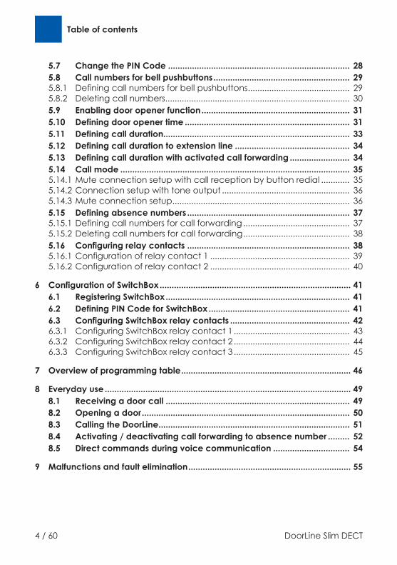
Table of contents
4 / 60 DoorLine Slim DECT
5.7 Change the PIN Code ............................................................................ 285.8 Call numbers for bell pushbuttons......................................................... 295.8.1 Defining call numbers for bell pushbuttons........................................... 295.8.2 Deleting call numbers.............................................................................. 305.9 Enabling door opener function.............................................................. 315.10 Defining door opener time ..................................................................... 315.11 Defining call duration.............................................................................. 335.12 Defining call duration to extension line ................................................ 345.13 Defining call duration with activated call forwarding ......................... 345.14 Call mode ................................................................................................ 355.14.1 Mute connection setup with call reception by button redial ............ 355.14.2 Connection setup with tone output ...................................................... 365.14.3 Mute connection setup........................................................................... 365.15 Defining absence numbers .................................................................... 375.15.1 Defining call numbers for call forwarding............................................. 375.15.2 Deleting call numbers for call forwarding............................................. 385.16 Configuring relay contacts .................................................................... 385.16.1 Configuration of relay contact 1 ........................................................... 395.16.2 Configuration of relay contact 2 ........................................................... 40
6 Configuration of SwitchBox................................................................................ 416.1 Registering SwitchBox............................................................................. 416.2 Defining PIN Code for SwitchBox ........................................................... 416.3 Configuring SwitchBox relay contacts .................................................. 426.3.1 Configuring SwitchBox relay contact 1 ................................................. 436.3.2 Configuring SwitchBox relay contact 2 ................................................. 446.3.3 Configuring SwitchBox relay contact 3 ................................................. 45
7 Overview of programming table....................................................................... 46
8 Everyday use ....................................................................................................... 498.1 Receiving a door call ............................................................................. 498.2 Opening a door....................................................................................... 508.3 Calling the DoorLine................................................................................ 518.4 Activating / deactivating call forwarding to absence number ......... 528.5 Direct commands during voice communication ................................ 54
9 Malfunctions and fault elimination.................................................................... 55

Table of contents
DoorLine Slim DECT 5 / 60
10 Maintenance, care and disposal...................................................................... 5610.1 Cleaning................................................................................................... 5610.2 Storage ..................................................................................................... 5610.3 Disassembly ............................................................................................. 5610.4 Disposal .................................................................................................... 5610.4.1 Disposing of packaging material ........................................................... 5610.4.2 Disposing of old device........................................................................... 56

2 Safety instructions
6 / 60 DoorLine Slim DECT
2 Safety instructionsBefore installing or using the product, it is essential to observe the instructions inthis manual.If you fail to follow these instructions, the manufacturer Telegärtner ElektronikGmbH will not accept any liability for any damage resulting from negligent ordeliberate disregard of the instructions in this operating manual!▪ Keep small parts and packaging well away from children. There is a danger
of suffocation.▪ Connect the product only to equipment that supplies SELV (Safety Extra
Low Voltage).▪ Only connect CE-certified end devices to the telephone system.▪ Do not connect devices that have equipotential bonding including earth-
ing on the lines.▪ Do not use damaged devices. Have a damaged device repaired immedi-
ately.▪ The lines must not be installed or connected during storms. Nor is it permit-
ted to insert or unplug the connection plug during storms.▪ The housing must not be opened under any circumstances. Unauthorised
opening, incorrect repairs or modification can result in dangers to the user.Warranty claims shall also be rendered void.
▪ Protect the product against dust, aggressive liquids and vapours.▪ Do not use the product in damp rooms or in potentially explosive areas.▪ Do not install your product near heat sources or other electrical devices.▪ Do not permit liquid to penetrate the interior of the product. This may result
in electric shock or short-circuits.▪ Route connecting lines and cables such that there is no risk of accidents!▪ The DoorLine Slim DECT contains a radio module based on the DECT stand-
ard. The operation of medical devices may be impaired. Note the tech-nical conditions of the respective environment, e.g. medical practice.

Product information and description 3
DoorLine Slim DECT 7 / 60
3 Product information and description
Fig. 1:
Item Description1 Bell pushbutton 1 (capacitance)
2 Bell pushbutton 2 (capacitance)
3 Brightness sensor
4 Microphone
5 Labelling panel
6 Loudspeaker (not visible)

3 Product information and description
8 / 60 DoorLine Slim DECT
3.1 Model variants
DoorLine Slim DECT
Surface Glass
Colour/Article number white 150720
black 150730
3.2 Nameplate
The nameplate contains the serial number, product coding and information onthe device type.
Product information and description 3
DoorLine Slim DECT 9 / 60
3.3 Specified useThe DoorLine is designed for connection to DECT-compatible PBX systems.It can be used▪ as an intercom▪ for remote-controlled opening of doors or gates▪ for relaying door conversations to telephones▪ for connection to other control systemsDoorLine has been developed for private as well as commercial use.
3.3.1 Notes on the use of an electronic door openerThere is an increased risk of burglary if you connect a door opener if the relaycontacts are accessible following disassembly of the DoorLine.It is safer to configure a door opener via a SwitchBox (accessories) because thisis located inside the house, which means that the relay contacts cannot bemanipulated from the outside.An electric door opener does not substitute door closure by a locking bar, it isan intelligent, additional safety feature.It is primarily intended for daytime operation, whereas at night time or in caseof absence the relevant door is locked by the locking bar.As far as insurance is concerned, a door that is held closed only by the use ofthe door opener is not regarded as locked!

3 Product information and description
10 / 60 DoorLine Slim DECT
3.4 Technical prerequisites▪ The DoorLine is designed for connection to DECT-compatible PBX systems.▪ Both relay switching outputs of the device connect potential-free. This
means that when a door opener or a similar device is activated, it may benecessary to provide an additional bell transformer (see chapter Connect-ing device [} 16]).
▪ Your PBX system and end devices (telephones) must support touch-tone di-alling (DTMF).
▪ The DoorLine is not suitable for complete surface mounting. We recom-mend assembly on a standard in-wall socket.
3.5 Technical dataConnection tothe base
Radio standard frequency rangeRange inside the buildingRange outdoors
DECT / GAP-compatible 1881 - 1897 MHzup to 40 m
up to 300 m
Bell pushbuttons Number 2
Call numbers Number per button 2 call numbers withmax. 20 positions
Relay switchingoutputs
Relay switching output 1Relay switching output 2
potential-free, 24 V AC / DC 1 Apotential-free, 24 V AC / DC 1 A
General data Power supplyCable length for powersupplyCurrent consumption
Degree of protectionOperating temperatureWeight
12 V / 12 W, controlled
max. 10 mStandby 1 WCall state max. 3.5 WIP54 (in installed state)-20 °C to +60 °C500 g
Dimensions Mounting plateDevice
176x79 mm220x85x21 mm
Product information and description 3
DoorLine Slim DECT 11 / 60
3.6 Accessories▪ Wall power supply SNG DL article number 105248
(For use as bell transformer, door opener current supply, etc. Cannot beused for power supply to the DoorLine Slim DECT!)
▪ Power unit for carrier rail assembly (DIN rail) HDR-15-12,article number 116715 (for voltage supply to the DoorLine Slim Dect).
▪ SwitchBox SB-442 article number 151003Surface mounting or assembly on carrier rail (DIN rail)– 4 PBX system connectable
(only in conjunction with DoorLine Slim and DoorLine Pro Exclusive)– Extends the DoorLine Slim DECT by three further relay contacts
4 Assembly and connection
12 / 60 DoorLine Slim DECT
4 Assembly and connection
4.1 For your safetyAssembly must only be carried out by specialists with corresponding skills andexperience. These persons must be able to detect dangers and to avoid pos-sible risks.The statutory specifications at the place of installation must be observed.Take care not to jam the connecting cables during installation.Also observe the safety instructions at the start of the Operating Instructions.
Caution: The front panel of the device is made of glass. It can be damagedand cause injury. Protect the glass surfaces against damage.
4.2 Scope of supplyThe scope of supply of the device includes:▪ the device▪ Assembly and Operating Instructions▪ mounting plate▪ sealing flange▪ bag with fastening material and Allen key▪ wall power supply

Assembly and connection 4
DoorLine Slim DECT 13 / 60
4.3 Prior to assemblyCheck all parts for completeness and transport damage prior to assembly.We recommend that you initially register the DoorLine in the direct vicinity ofyour PBX system, try it out and make the basic configuration.In this manner, you can install the wiring and configure the bell pushbuttonquickly and easily.After the DoorLine functions perfectly in this test setup with your TC system andtelephones, you can install the DoorLine in its final place of usage.
4.4 Place of installation▪ The device is intended for installation outdoors in an area protected from
splash water (moisture protection as per IP 54).▪ A minimum distance from the microphone to the nearest corner wall sur-
face of at least 10 cm must be observed.▪ The ambient temperature must be between -20 °C and +60 °C.▪ In the area of the installation location, no supply lines or similar must be in-
stalled.
4.5 Installing deviceThe device is installed on a standard in-wall socket or a corresponding cavitybe means of the enclosed mounting plate and fastening material.The device can be sealed at the top and the side with sealants such as siliconeor acryl.
Caution: Incorrect sealing can result in the formation of moisture. This cancause damage to the device. Do not seal the device at the bottom.

4 Assembly and connection
14 / 60 DoorLine Slim DECT
4.5.1 Installing mounting plate on the wall
Fig. 2:
1. Position the mounting plate (1) on a standard in-wall socket (2) or a suitablecavity in the masonry. The recess in the mounting plate must be fitted ac-curately on the in-wall socket.
2. Ensure that no supply lines, cables or similar are installed in the area of thedrilling holes (3).
3. Fasten the mounting plate via the two boreholes (3) onto the wall withscrews and dowels.
4. Press the sealing flange (4) into the recess on the mounting plate (1).

Assembly and connection 4
DoorLine Slim DECT 15 / 60
4.5.2 Installing device on mounting plate
Fig. 3:
1. Connect the terminals (1) (see chapter Connecting device [} 16]).
2. Insert the terminals (1) back into the device.3. Place the device diagonally from above onto the mounting plate until the
four metal lugs (2) engage in the four fastening holes of the device.
4. Secure the device with the hexagon socket-grub screw (3) on the mountingplate.Caution: Only tighten the screw lightly because otherwise the thread canbe damaged.

4 Assembly and connection
16 / 60 DoorLine Slim DECT
4.6 Connecting device
4.6.1 Important notes▪ Before connecting the device to the PBX system, switch off all required
components and those connected to the DoorLine (bell transformer, powerunit).
▪ When installing the wiring, ensure that the polarity (12 V DC voltage) of thetwo wires in the terminals is correct.
▪ Do not insert the wall power supply into the socket until all wires are firmlyconnected and there is no risk of a short circuit of wire pairs.
▪ A bell transformer (e.g. 12 V alternating voltage) must not be used as apower supply for the device. This can result in destruction of the device!
▪ Both integrated relay contacts connect potential-free, i.e an additional belltransformer is required to activate a door opener. Then connect the belltransformer voltage via the respective relay switching output to the dooropener (see chapter Connection example for a door opener and a doorbell [} 20]).
▪ Both switching relays can be loaded to a max. of 24 V AC / DC 1 A. Prior toinitial operation of the device, ensure that these values are not exceededby your door opener, door bell or other devices to be connected. Observethe Operating Instructions of the respective products.

Assembly and connection 4
DoorLine Slim DECT 17 / 60
4.6.2 WiringFor the installation wiring of the relay contacts, SwitchBox and power supply ofthe device, use commercially available telecommunication cables.Please note that in order to meet general safety provision and to avoid interfer-ence influences, the low-current lines must be routed separately from powerlines.Observe a minimum distance of 10 cm between both types of lines. If one ofthe connected lines is routed out-of-doors, you will have to provide sufficientlightning protection.
Lines types that can be used▪ Telecommunication indoor cable
– J-Y(ST)-Y 2 x 2 x 0.6– J-Y(ST)-Y 2 x 2 x 0.8– J-Y(ST)-Y 4 x 2 x 0.6– J-Y(ST)-Y 4 x 2 x 0.8
▪ Bell sheathed cable– YR 4 x 0.8
▪ Telecommunications cable– A-2Y(L)2Y 4 x 2 x 0.8
Maximum cable lengths for connection to door opener
Wire diameter 0.8 mm 0.6 mmRanges for door opener operation from an ex-ternal bell transformer to door opener (max-imum current consumption 1A alternatingvoltage)
12 V16 V20 V24 V
38 m76 m
115 m177 m
17 m34 m51 m78 m

4 Assembly and connection
18 / 60 DoorLine Slim DECT
4.6.3 Terminal assignmentThe rear side of the device has two screw-in/terminal plug-in connectors. Theycan be unplugged for convenient connection of the lines.Labelling is on the rear side of the housing.
View from the rear View of terminals
1 Supply voltage +12 V 7 SwitchBox data
2 Supply voltage GND 8 SwitchBox -
3 Relay contact 2potential-free
9 SwitchBox +
4 Relay contact 2 potential-free
10 not assigned
5 Relay contact 1 potential-free
11 not assigned
6 Relay contact 1 potential-free

Assembly and connection 4
DoorLine Slim DECT 19 / 60
4.6.4 Wiring diagram
Fig. 4:
Item DescriptionA DoorLine (rear side)
B Wall power supply
C DECT-compatible PBX system
D SwitchBox
E Relay contact 2
F Relay contact 1

4 Assembly and connection
20 / 60 DoorLine Slim DECT
4.6.5 Connection example for a door opener and a door bell
Item DescriptionA DoorLine (rear side)
B Wall power supply
G Door bell to relay contact 1
H Door opener to relay contact 2
I Bell transformer

Assembly and connection 4
DoorLine Slim DECT 21 / 60
4.6.6 DoorLine registrationNote: The DoorLine permits registration to a PBX system only during the first15 minutes after application of the power supply. Readiness for registration canbe activated again for 15 minutes at any time by briefly interrupting thevoltage supply.The DECT-PIN of the DoorLine cannot be changed and is permanently set to0000. If a different DECT PIN is configured on your PBX system, it must bechanged prior to registration to 0000.
Important: The DECT-PIN is not the PIN code for configuration of the DoorLineSlim DECT.Further information on changing the DECT-PIN is available in the Operating In-structions of your PBX system.
The DoorLine remains for up to 2 minutes in registration mode. If youhave to cover a long distance to reach your PBX system, first changethe DoorLine to registration mode. The time required can vary accord-ing to the PBX system.
1. Apply the voltage supply.ð The DoorLine starts up. If the surrounding area is dark, the DoorLine light-
ing switches on.2. Switch your PBX system to registration mode.3. Actuate both bell pushbuttons for 5 seconds.
ð Press both buttons at the same time because otherwise normal ringing ofthe bell will be detected.
ð When the button is pressed, a double acknowledgement tone soundsimmediately.
ð After 5 seconds, a single acknowledgement tone sounds. The buttonscan now be released. The DoorLine registers at the base which is nowready for registration.
4. After successful registration, a double acknowledgement tone sounds.ð Your PBX system assigns a new internal call number for the DoorLine. The
DoorLine can now be reached and can call under this call number.ð If registration is unsuccessful, a negative acknowledgement tone sounds
(eight short beeps in succession). Registration could not be carried outsuccessfully and has to be restarted.

4 Assembly and connection
22 / 60 DoorLine Slim DECT
ð In the case of a restart of the DoorLine, it checks into the previously re-gistered PBX system automatically. After every successful check-in, adouble acknowledgement tone sounds.
4.6.7 Checking connectionNote: Due to the registration via DECT, the DoorLine is treated by your PBX sys-tem like a conventional wireless telephone.If you receive a call from outside, all telephones that were assigned to this ex-ternal number ring. Depending on the PBX system, after initial registration theDoorLine will probably be assigned automatically to an external number, i.e. allcalls are also forwarded to the DoorLine. After the first bell signal, the DoorLineautomatically receives all calls. The caller would thus be connected to theDoorLine.A remedy in such a case can be provided by reconfiguring your PBX system. Ithas to be set such that the DoorLine does not react to external calls1. Call the DoorLine from a telephone that is connected to your PBX system
(see chapter Calling the DoorLine [} 51])ð A double tone sounds in the telephone. The voice communication
between telephone and DoorLine is then built up.ð If the device does not react, disconnect it immediately from the power-
supply system. Now check the connection of terminals 1 and 2 to thewall power supply for a wiring fault (e.g. reverse polarity of line).
2. After registration of the DoorLine, check the configuration of your PBX sys-tem. The PBX system is treated like a conventional wireless telephone. It hasto be set such that the DoorLine does not react to external calls.
4.6.8 Check of DECT signal strengthAfter the voltage supply is applied, the background lighting flashes for the first60 seconds to indicating the DECT signal strength.

Assembly and connection 4
DoorLine Slim DECT 23 / 60
Meaning of the flashing signals:
3-fold flashing Strong signal
2-fold flashing Medium signal
1-fold flashing Weak signal
Continuous flashing No connection to the PBX system or not registered
No flashing Signal present but too weak for reliable operation
Continuous flashing is always displayed in addition if the DoorLine has not con-nection to the PBX system.
4.7 Labelling bell pushbuttons

4 Assembly and connection
24 / 60 DoorLine Slim DECT
1. Pull down the drawer (1) with the help of the enclosed Allen key (2) to re-move it.
2. Remove the paper.3. Label the paper as desired.4. Place the paper in the drawer.5. Push the drawer to close it.
Insertion label blankPaper size: 50x69.5 mm
Fig. 5:
You can find our Label Assistant on our home page under the Productdescription of the device. It helps you with simple and professional la-belling of the insertion label.

Configuration 5
DoorLine Slim DECT 25 / 60
5 Configuration
5.1 Factory settingsThe following parameters are preset ex works:
PIN Code 0000
Door opener function Blocked
Door opener time 3 seconds
Call duration 1 minute
Door call duration 30 seconds
Call number, bell pushbutton 1 **91
Call number, bell pushbutton 2 **92
Call reception Mute connection setup
Configuration of relay contact 1 External gong for all bell pushbuttons
Configuration of relay contact 2 Door opener
SwitchBox None
5.2 Restoring factory settings1. Enter the configuration mode (see chapter Entry to config-
uration mode [} 26])
2. Actuate the hashtag button and star button on the tele-phone
3. Enter configuration command "99" at the telephone
A melody rings out. After approx. 3 seconds you hear thepositive acknowledgement tone.The device is now in delivery status.
Note: When restoring the factory settings of the DoorLine, the registered PBXsystem is not deleted!

5 Configuration
26 / 60 DoorLine Slim DECT
5.3 Acknowledgement tonesDuring programming, you will be informed about the positive and negative ac-knowledgement tones via the programming status.Each note symbol corresponds to a beep:
neutral Key input is expected ♪
positive The programming has been accepted ♪♪
negative The programming has not been accepted ♪♪♪♪♪♪♪♪
5.4 Saving and ending configurationTo end the configuration, it is sufficient to hang up the telephone receiver. Thedevice then detects the end of the call automatically and saves the changedconfiguration.
5.5 Entry to configuration modeFor configuration, you have to call your DoorLine with a touch-tone diallingtelephone. The way you can call the DoorLine depends on the configuration ofyour PBX system.When the connection to the device has been established, you can start withthe configuration.
Notes▪ Write down the corresponding codes for your own reference before you
start the configuration.▪ In programming mode, the call duration is unlimited.▪ If the programming is rejected by the device (negative acknowledgement
tone), you will have to repeat the incorrect programming step.▪ If you entered the wrong PIN three times in succession, the connection is dis-
connected.

Configuration 5
DoorLine Slim DECT 27 / 60
1 Pick up the receiver
2 Call the device
You will hear the positive acknowledgement tone
3 Actuate the hashtag button twice on the telephone
You will hear the neutral acknowledgement tone
4 Enter the PIN
You will hear the positive acknowledgement and are nowin programming mode
If you hear the positive acknowledgement tone, you can start with the pro-gramming. Otherwise the procedure must be repeated.If you are in programming mode, you can carry out all configuration optionsone after the other.
5.6 Defining microphone sensitivity and volumeThe microphone sensitivity and volume of the loudspeaker can be set in 10stages. When the maximum or minimum possible value is reached, you willhear a positive acknowledgement tone. Each correct key input is confirmedby a neutral acknowledgement tone.
The following code numbers are possible:
Code number 2 reduces the microphone sensitivity
Code number 3 increases the microphone sensitivity
Code number 5 reduces the loudspeaker sensitivity
Code number 6 increases the loudspeaker sensitivity

5 Configuration
28 / 60 DoorLine Slim DECT
5.7 Change the PIN CodeIn delivery status, the PIN Code for the configuration is "0000". To prevent thesettings of your DoorLine from being changed by unauthorised persons, youshould change the PIN Code as follows:
1. Enter the configuration mode (see chapter Entry to config-uration mode [} 26])
2. Actuate the hashtag button and star button on the tele-phone
3. Enter configuration command "88" at the telephone
You will hear the neutral acknowledgement tone
4. Enter new 4-digit PIN Code
You will hear the neutral acknowledgement tone
5. Repeat new PIN Code
You will hear the positive acknowledgement tone
If changing of the PIN Code is not completed with the positive ac-knowledgement tone, check whether the correct PIN Code was inputwhen you entered the configuration mode. This is not checked by theDoorLine until the end of the complete procedure.
Changes to the configuration are only possible with knowledge of yourPIN Code. For security reasons, enter your new PIN Code in the config-uration table (see Overview of configuration commands [} 46]).
Configuration 5
DoorLine Slim DECT 29 / 60
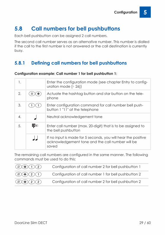
5.8 Call numbers for bell pushbuttonsEach bell pushbutton can be assigned 2 call numbers.The second call number serves as an alternative number. This number is dialledif the call to the first number is not answered or the call destination is currentlybusy.
5.8.1 Defining call numbers for bell pushbuttons
Configuration example: Call number 1 for bell pushbutton 1:
1. Enter the configuration mode (see chapter Entry to config-uration mode [} 26])
2. Actuate the hashtag button and star button on the tele-phone
3. Enter configuration command for call number bell push-button 1 "11" at the telephone
4. Neutral acknowledgement tone
5. Enter call number (max. 20-digit) that is to be assigned tothe bell pushbutton
If no input is made for 5 seconds, you will hear the positiveacknowledgement tone and the call number will besaved
The remaining call numbers are configured in the same manner. The followingcommands must be used to do this:
Configuration of call number 2 for bell pushbutton 1
Configuration of call number 1 for bell pushbutton 2
Configuration of call number 2 for bell pushbutton 2

5 Configuration
30 / 60 DoorLine Slim DECT
5.8.2 Deleting call numbersYou can delete a call number that is saved on a button.
Configuration example: Deleting call number 1 for bell pushbutton 1:
1. Enter the configuration mode (see chapter Entry to config-uration mode [} 26])
2. Actuate the hashtag button and star button on the tele-phone
3. Enter configuration command for call number bell push-button 1 "11" at the telephone
4. Neutral acknowledgement tone
5. If no input is made for 5 seconds, you will hear the positiveacknowledgement tone and the call number will be de-leted
The remaining call numbers are deleted in the same manner. The followingcommands must be used to do this:
Deletion of call number 2 for bell pushbutton 1
Deletion of call number 1 for bell pushbutton 2
Deletion of call number 2 for bell pushbutton 2

Configuration 5
DoorLine Slim DECT 31 / 60
5.9 Enabling door opener functionFor security reasons to prevent unauthorised opening, the door cannot beopened if the connection was set up from the telephone to the door intercom.This function can be deactivated if desired.
1. Enter the configuration mode (see chapter Entry to config-uration mode [} 26])
2. Actuate the hashtag button and star button on the tele-phone
3. Enter configuration command "04" at the telephone
As confirmation, you will hear a neutral acknowledgementtone
4. Enter digit 1 to enable the door opener function or
digit 0 to block the door opener function
Finally, you will hear the positive acknowledgement tone
5.10 Defining door opener timeActuation time of the door opener.Possible values: 1 to 9 seconds or deactivate with 0Delivery status: 3 seconds
With door opening with redial #9If relay contact 2 was defined as door openerorif a contact of a SwitchBox was defined as door opener with redial #9.

5 Configuration
32 / 60 DoorLine Slim DECT
1. Enter the configuration mode (see Entry to configurationmode [} 26])
2. Actuate the hashtag button and star button on the tele-phone
3. Enter configuration command "05" at the telephone
As confirmation, you will hear a neutral acknowledgementtone
4. Define the switching time of the door opener by enteringthe digits 1 to 9 (digit corresponds to the duration inseconds, 0=deactivated)
Finally, you will hear the positive acknowledgement tone
With door opening with redial #8If relay contact 1 was defined as door openerorif a contact of a SwitchBox was defined as door opener with redial #8.
1. Enter the configuration mode (see Entry to configurationmode [} 26])
2. Actuate the hashtag button and star button on the tele-phone
3. Enter configuration command "03" at the telephone
As confirmation, you will hear a neutral acknowledgementtone
4. Define the switching time of the door opener by enteringthe digits 1 to 9 (digit corresponds to the duration inseconds, 0=deactivated)
Finally, you will hear the positive acknowledgement tone

Configuration 5
DoorLine Slim DECT 33 / 60
5.11 Defining call durationDefinition of the call duration for the DoorLine. When this time has elapsed, the door conversation is disconnected automatic-ally.Delivery status: one minutePossible values: 1 to 9 minutes in steps of 1 minute or 0 for "without limitation".
1. Enter the configuration mode (see Entry to configurationmode [} 26])
2. Actuate the hashtag button and star button on the tele-phone
3. Enter configuration command "07" at the telephone
As confirmation, you will hear a neutral acknowledgementtone
4. Define the call duration by entering the digits 1 to 9 (digitcorresponds to the duration in minutes, 0=without limita-tion)
Finally, you will hear the positive acknowledgement tone

5 Configuration
34 / 60 DoorLine Slim DECT
5.12 Defining call duration to extension lineDefinition of the duration of the door call to the extension line of your PBX sys-tem.Delivery status: 30 secondsPossible values: 1 to 99 seconds.
1. Enter the configuration mode (see Entry to configurationmode [} 26])
2. Actuate the hashtag button and star button on the tele-phone
3. Enter configuration command "08" at the telephone
As confirmation, you will hear a neutral acknowledgementtone
4. Enter call duration with digits 01, ... 99 (in steps of onesecond). The input must have two digits
Finally, you will hear the positive acknowledgement tone
5.13 Defining call duration with activated callforwarding
This command can be used to define the call duration when call forwarding isactivated (see Activating / deactivating call forwarding to absence number[} 52]).If the door call is forwarded to an external destination (e.g., a mobile tele-phone), the call duration may have to be extended accordingly due to thelonger call setup.Delivery status: 30 secondsPossible values: 1 to 99 seconds.
1. Enter the configuration mode (see Entry to configurationmode [} 26])
2. Actuate the hashtag button and star button on the tele-phone

Configuration 5
DoorLine Slim DECT 35 / 60
3. Enter configuration command "09" at the telephone
As confirmation, you will hear a neutral acknowledgementtone
4. Enter call duration with digits 01, ... 99 (in steps of onesecond). The input must have two digits
Finally, you will hear the positive acknowledgement tone
5.14 Call modeCall mode determines the way the DoorLine Slim DECT sets up a call to the re-mote station.
5.14.1 Mute connection setup with call reception bybutton redial
The loudspeaker of the DoorLine is switched to mute during the complete callsetup. The voice connection between DoorLine and telephone is not estab-lished until the receiver of the called telephone is picked up and a random di-git key has been pressed on the telephone.
5 Configuration
36 / 60 DoorLine Slim DECT
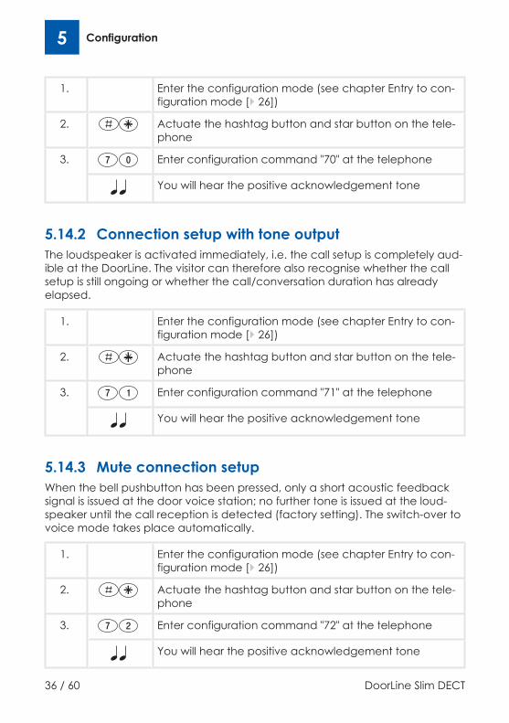
1. Enter the configuration mode (see chapter Entry to con-figuration mode [} 26])
2. Actuate the hashtag button and star button on the tele-phone
3. Enter configuration command "70" at the telephone
You will hear the positive acknowledgement tone
5.14.2 Connection setup with tone outputThe loudspeaker is activated immediately, i.e. the call setup is completely aud-ible at the DoorLine. The visitor can therefore also recognise whether the callsetup is still ongoing or whether the call/conversation duration has alreadyelapsed.
1. Enter the configuration mode (see chapter Entry to con-figuration mode [} 26])
2. Actuate the hashtag button and star button on the tele-phone
3. Enter configuration command "71" at the telephone
You will hear the positive acknowledgement tone
5.14.3 Mute connection setupWhen the bell pushbutton has been pressed, only a short acoustic feedbacksignal is issued at the door voice station; no further tone is issued at the loud-speaker until the call reception is detected (factory setting). The switch-over tovoice mode takes place automatically.
1. Enter the configuration mode (see chapter Entry to con-figuration mode [} 26])
2. Actuate the hashtag button and star button on the tele-phone
3. Enter configuration command "72" at the telephone
You will hear the positive acknowledgement tone
Configuration 5
DoorLine Slim DECT 37 / 60
5.15 Defining absence numbersTwo call numbers can be saved to which door calls can be redirected as re-quired.The second call number is an alternative number which is dialled if the call tothe first number is not answered or the call destination is currently busy.Call forwarding to these call numbers can be activated/deactivated for eachbell pushbutton as required (see chapter Activating / deactivating call for-warding to absence number [} 52]).
Precondition for call forwarding to an external destinationThe extension line on which the DoorLine is registered must have an authorisa-tion for receiving external telephone calls.In most telephone systems this function is referred to as "direct outward dial-ling".
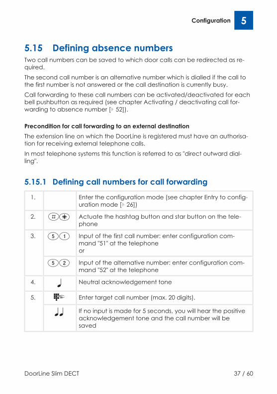
5.15.1 Defining call numbers for call forwarding
1. Enter the configuration mode (see chapter Entry to config-uration mode [} 26])
2. Actuate the hashtag button and star button on the tele-phone
3. Input of the first call number: enter configuration com-mand "51" at the telephoneor
Input of the alternative number: enter configuration com-mand "52" at the telephone
4. Neutral acknowledgement tone
5. Enter target call number (max. 20 digits).
If no input is made for 5 seconds, you will hear the positiveacknowledgement tone and the call number will besaved
5 Configuration
38 / 60 DoorLine Slim DECT
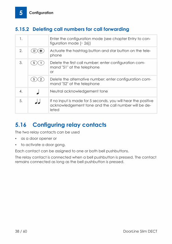
5.15.2 Deleting call numbers for call forwarding
1. Enter the configuration mode (see chapter Entry to con-figuration mode [} 26])
2. Actuate the hashtag button and star button on the tele-phone
3. Delete the first call number: enter configuration com-mand "51" at the telephoneor
Delete the alternative number: enter configuration com-mand "52" at the telephone
4. Neutral acknowledgement tone
5. If no input is made for 5 seconds, you will hear the positiveacknowledgement tone and the call number will be de-leted
5.16 Configuring relay contactsThe two relay contacts can be used▪ as a door opener or▪ to activate a door gong.Each contact can be assigned to one or both bell pushbuttons.The relay contact is connected when a bell pushbutton is pressed. The contactremains connected as long as the bell pushbutton is pressed.

Configuration 5
DoorLine Slim DECT 39 / 60
5.16.1 Configuration of relay contact 1
1. Enter the configuration mode (see chapter Entry to con-figuration mode [} 26])
2. Actuate the hashtag button and star button on the tele-phone
3. Enter configuration command "61" at the telephone
Neutral acknowledgement tone
4. Enter switching command in accordance with the follow-ing table
You will hear the positive acknowledgement tone as con-firmation
Switchingcommand
Bell push-button
Bell push-button
Redial Comments
1 2 #80 - - Relay contact 1 connects with
redial of #8 during voice com-munication.
1 - -
2 - -
3 - Factory setting.
Example: You wish to assign relay contact 1 to bell pushbutton 2 to actuate adoor gong. After entry to the configuration mode, enter the following in theconfiguration for this purpose:#à61 ⇒ wait for neutral tone ⇒ 2 ⇒ positive acknowledgement tone sounds.

5 Configuration
40 / 60 DoorLine Slim DECT
5.16.2 Configuration of relay contact 2
Configuration of relay contact 2
1. Enter the configuration mode (see chapter Entry to con-figuration mode [} 26])
2. Actuate the hashtag button and star button on the tele-phone
3. Enter configuration command "62" at the telephone
Neutral acknowledgement tone
4. Enter switching command in accordance with the follow-ing table
You will hear the positive acknowledgement tone as con-firmation
Switchingcommand
Bell push-button
Bell push-button
Redial Comments
1 2 #90 - - Relay contact 2 connects with
redial of #9 during voice com-munication. Factory setting.
1 - -
2 - -
3 -
Configuration of SwitchBox 6
DoorLine Slim DECT 41 / 60
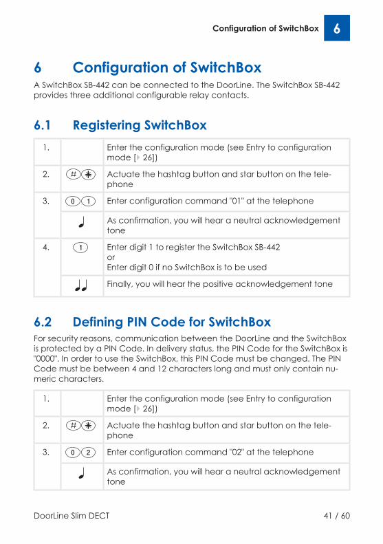
6 Configuration of SwitchBoxA SwitchBox SB-442 can be connected to the DoorLine. The SwitchBox SB-442provides three additional configurable relay contacts.
6.1 Registering SwitchBox1. Enter the configuration mode (see Entry to configuration
mode [} 26])
2. Actuate the hashtag button and star button on the tele-phone
3. Enter configuration command "01" at the telephone
As confirmation, you will hear a neutral acknowledgementtone
4. Enter digit 1 to register the SwitchBox SB-442orEnter digit 0 if no SwitchBox is to be used
Finally, you will hear the positive acknowledgement tone
6.2 Defining PIN Code for SwitchBoxFor security reasons, communication between the DoorLine and the SwitchBoxis protected by a PIN Code. In delivery status, the PIN Code for the SwitchBox is"0000". In order to use the SwitchBox, this PIN Code must be changed. The PINCode must be between 4 and 12 characters long and must only contain nu-meric characters.
1. Enter the configuration mode (see Entry to configurationmode [} 26])
2. Actuate the hashtag button and star button on the tele-phone
3. Enter configuration command "02" at the telephone
As confirmation, you will hear a neutral acknowledgementtone
6 Configuration of SwitchBox
42 / 60 DoorLine Slim DECT
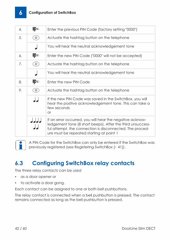
4. Enter the previous PIN Code (factory setting "0000")
5. Actuate the hashtag button on the telephone
You will hear the neutral acknowledgement tone
6. Enter the new PIN Code ("0000" will not be accepted)
7. Actuate the hashtag button on the telephone
You will hear the neutral acknowledgement tone
8. Enter the new PIN Code
9. Actuate the hashtag button on the telephone
If the new PIN Code was saved in the SwitchBox, you willhear the positive acknowledgement tone. This can take afew secondsor
If an error occurred, you will hear the negative acknow-ledgement tone (8 short beeps). After the third unsuccess-ful attempt, the connection is disconnected. The proced-ure must be repeated starting at point 1
A PIN Code for the SwitchBox can only be entered if the SwitchBox waspreviously registered (see Registering SwitchBox [} 41]).
6.3 Configuring SwitchBox relay contactsThe three relay contacts can be used▪ as a door opener or▪ to activate a door gong.Each contact can be assigned to one or both bell pushbuttons.The relay contact is connected when a bell pushbutton is pressed. The contactremains connected as long as the bell pushbutton is pressed.
Configuration of SwitchBox 6
DoorLine Slim DECT 43 / 60
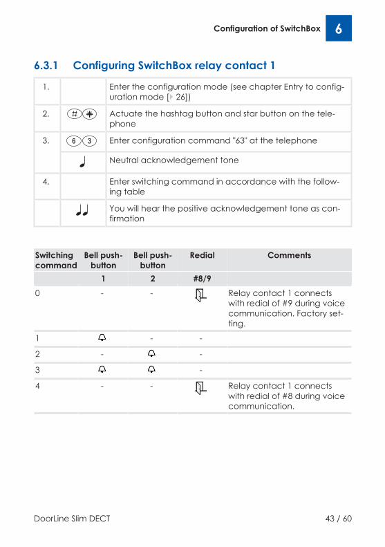
6.3.1 Configuring SwitchBox relay contact 1
1. Enter the configuration mode (see chapter Entry to config-uration mode [} 26])
2. Actuate the hashtag button and star button on the tele-phone
3. Enter configuration command "63" at the telephone
Neutral acknowledgement tone
4. Enter switching command in accordance with the follow-ing table
You will hear the positive acknowledgement tone as con-firmation
Switchingcommand
Bell push-button
Bell push-button
Redial Comments
1 2 #8/90 - - Relay contact 1 connects
with redial of #9 during voicecommunication. Factory set-ting.
1 - -
2 - -
3 -
4 - - Relay contact 1 connectswith redial of #8 during voicecommunication.

6 Configuration of SwitchBox
44 / 60 DoorLine Slim DECT
6.3.2 Configuring SwitchBox relay contact 2
1. Enter the configuration mode (see chapter Entry to config-uration mode [} 26])
2. Actuate the hashtag button and star button on the tele-phone
3. Enter configuration command "64" at the telephone
Neutral acknowledgement tone
4. Enter switching command in accordance with the follow-ing table
You will hear the positive acknowledgement tone as con-firmation
Switchingcommand
Bell push-button
Bell push-button
Redial Comments
1 2 #8/90 - - Relay contact 2 connects with
redial of #9 during voice com-munication.
1 - - Factory setting.
2 - -
3 -
4 - - Relay contact 2 connects withredial of #8 during voice com-munication.

Configuration of SwitchBox 6
DoorLine Slim DECT 45 / 60
6.3.3 Configuring SwitchBox relay contact 3
1. Enter the configuration mode (see chapter Entry to config-uration mode [} 26])
2. Actuate the hashtag button and star button on the tele-phone
3. Enter configuration command "65" at the telephone
Neutral acknowledgement tone
4. Enter switching command in accordance with the follow-ing table
You will hear the positive acknowledgement tone as con-firmation
Switchingcommand
Bell push-button
Bell push-button
Redial Comments
1 2 #8/90 - - Relay contact 3 connects with
redial of #9 during voice com-munication.
1 - -
2 - - Factory setting.
3 -
4 - - Relay contact 3 connects withredial of #8 during voice com-munication.
7 Overview of programming table
46 / 60 DoorLine Slim DECT
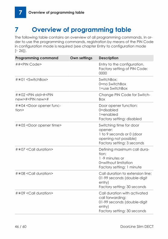
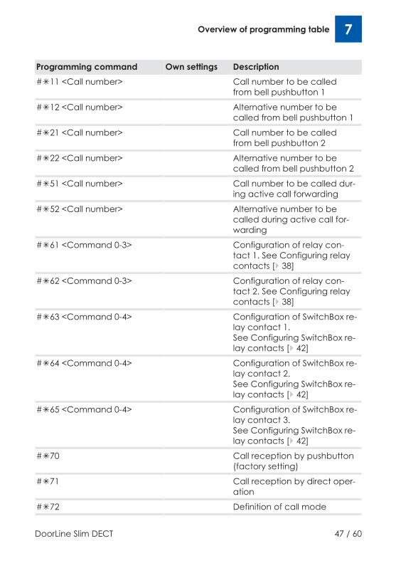
7 Overview of programming tableThe following table contains an overview of all programming commands. In or-der to use the programming commands, registration by means of the PIN Codein configuration mode is required (see chapter Entry to configuration mode[} 26]).
Programming command Own settings Description##<PIN Code> Entry to the configuration.
Factory setting of PIN Code:0000
#à01 <SwitchBox> SwitchBox:0=no SwitchBox1=use SwitchBox
#à02 <PIN old>#<PINnew>#<PIN new>#
Change PIN Code for Switch-Box
#à04 <Door opener func-tion>
Door opener function:0=disabled1=enabledFactory setting: disabled
#à05 <Door opener time> Switching time for dooropener:1 to 9 seconds or 0 (dooropening not possible)Factory setting: 3 seconds
#à07 <Call duration> Defining maximum call dura-tion:1 -9 minutes or0=without limitationFactory setting: 1 minute
#à08 <Call duration> Call duration to extension line:01-99 seconds (double-digitentry)Factory setting: 30 seconds
#à09 <Call duration> Call duration with activatedcall forwarding:01-99 seconds (double-digitentry)Factory setting: 30 seconds
Overview of programming table 7
DoorLine Slim DECT 47 / 60
Programming command Own settings Description#à11 <Call number> Call number to be called
from bell pushbutton 1
#à12 <Call number> Alternative number to becalled from bell pushbutton 1
#à21 <Call number> Call number to be calledfrom bell pushbutton 2
#à22 <Call number> Alternative number to becalled from bell pushbutton 2
#à51 <Call number> Call number to be called dur-ing active call forwarding
#à52 <Call number> Alternative number to becalled during active call for-warding
#à61 <Command 0-3> Configuration of relay con-tact 1. See Configuring relaycontacts [} 38]
#à62 <Command 0-3> Configuration of relay con-tact 2. See Configuring relaycontacts [} 38]
#à63 <Command 0-4> Configuration of SwitchBox re-lay contact 1. See Configuring SwitchBox re-lay contacts [} 42]
#à64 <Command 0-4> Configuration of SwitchBox re-lay contact 2. See Configuring SwitchBox re-lay contacts [} 42]
#à65 <Command 0-4> Configuration of SwitchBox re-lay contact 3. See Configuring SwitchBox re-lay contacts [} 42]
#à70 Call reception by pushbutton(factory setting)
#à71 Call reception by direct oper-ation
#à72 Definition of call mode
7 Overview of programming table
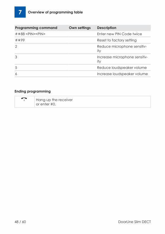
48 / 60 DoorLine Slim DECT
Programming command Own settings Description#à88 <PIN><PIN> Enter new PIN Code twice
#à99 Reset to factory setting
2 Reduce microphone sensitiv-ity
3 Increase microphone sensitiv-ity
5 Reduce loudspeaker volume
6 Increase loudspeaker volume
Ending programming
Hang up the receiveror enter #0.
Everyday use 8
DoorLine Slim DECT 49 / 60
8 Everyday use
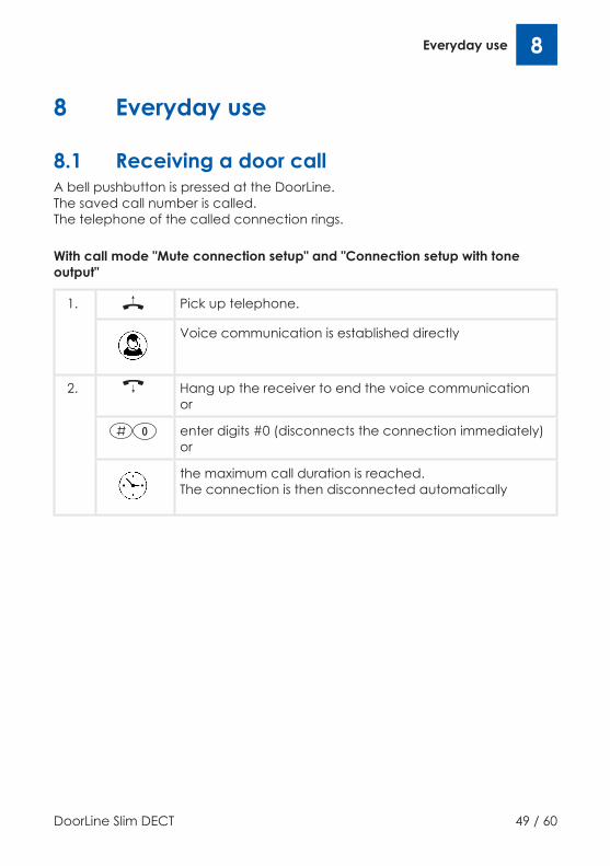
8.1 Receiving a door callA bell pushbutton is pressed at the DoorLine. The saved call number is called. The telephone of the called connection rings.
With call mode "Mute connection setup" and "Connection setup with toneoutput"
1. Pick up telephone.
Voice communication is established directly
2. Hang up the receiver to end the voice communicationor
enter digits #0 (disconnects the connection immediately)or
the maximum call duration is reached. The connection is then disconnected automatically

8 Everyday use
50 / 60 DoorLine Slim DECT
With call mode "Mute connection setup with call reception by button redial"
1. Pick up telephone. An attention tone (beep) indicates acall from the DoorLine
Actuate a random numeric key
Voice communication is established directly
2. Simply hang up the receiver to end the voice communic-ationor
enter digits #0 (disconnects the connection immediately)or
the maximum call duration is reached. The connection is then disconnected automatically
8.2 Opening a door1. A door call takes place
2. enter button command #8 (if relay contact 1 is set as dooropener)or
Enter button command #9 (if relay contact 2 is set as dooropener)
The door opener is activated
Everyday use 8
DoorLine Slim DECT 51 / 60
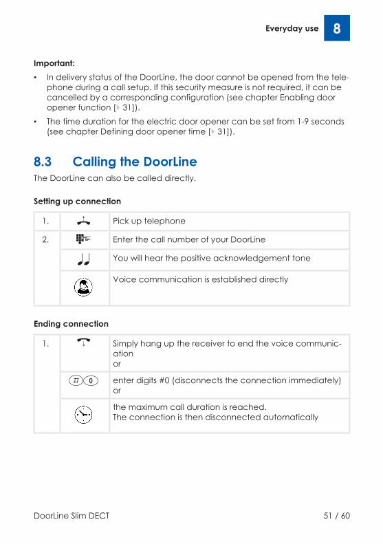
Important:▪ In delivery status of the DoorLine, the door cannot be opened from the tele-
phone during a call setup. If this security measure is not required, it can becancelled by a corresponding configuration (see chapter Enabling dooropener function [} 31]).
▪ The time duration for the electric door opener can be set from 1-9 seconds(see chapter Defining door opener time [} 31]).
8.3 Calling the DoorLineThe DoorLine can also be called directly.
Setting up connection
1. Pick up telephone
2. Enter the call number of your DoorLine
You will hear the positive acknowledgement tone
Voice communication is established directly
Ending connection
1. Simply hang up the receiver to end the voice communic-ationor
enter digits #0 (disconnects the connection immediately)or
the maximum call duration is reached. The connection is then disconnected automatically

8 Everyday use
52 / 60 DoorLine Slim DECT
8.4 Activating / deactivating call forwarding toabsence number
Example:You leave the house and are expecting a parcel service or important visitor.When you leave your house, you can now simply forward the door call to yourmobile telephone or another telephone.
Prerequisites:The call numbers for call forwarding must be defined in advance (see chapterDefining absence numbers [} 37]).
Activating call forwarding
1. Pick up telephone
2. Call the DoorLine
You will hear the positive acknowledgement tone
3. Press the hashtag button
4. Enter digit (1-2) for the relevant bell pushbutton
5. Enter digit 1 for activation
You will hear the positive acknowledgement tone. Forward-ing is active
6. Hang up the receiver

Everyday use 8
DoorLine Slim DECT 53 / 60
Deactivating call forwarding
1. Pick up telephone
2. Call the DoorLine
You will hear the positive acknowledgement tone
3. Press the hashtag button
4. Enter digit (1-2) for the relevant bell pushbutton
5. Enter digit 0 for deactivation
You will hear the positive acknowledgement tone. Forward-ing is deactivated
6. Hang up the receiver

8 Everyday use
54 / 60 DoorLine Slim DECT
8.5 Direct commands during voicecommunication
During a door call, you have the following additional input options on your tele-phone:
Disconnects the connection immediately. DoorLine movesto standby
Deactivates call forwarding to absence numbers button 1
Activates call forwarding to absence numbers button 1
Deactivates call forwarding to absence numbers button 2
Activates call forwarding to absence numbers button 2
orActivates the door openerFunction is only available if▪ a relay contact is configured as door opener and
– the door call was set up by the DoorLine or
– the door opener function was enabled in the config-uration of the DoorLine
Important: The contacts can only be switched via these direct commands if they havebeen assigned the function "Redial" in the configuration.

Malfunctions and fault elimination 9
DoorLine Slim DECT 55 / 60
9 Malfunctions and fault eliminationThe following table contains the most frequently occurring malfunctions andtheir correction. In case of other malfunctions, please contact specialist dealeror our technical Hotline (see rear side of device).
Malfunction Reason Solution
No function No operating voltage Check installation.Check Connections atthe terminals for correctconnection order.
Rapid continuous flash-ing of the button lamp
DoorLine is not re-gistered in the tele-phone system. RegisterDoorLine in accordancewith chapter DoorLineregistration [} 21] in thetelephone system.
Rapid continuous flash-ing of the button lamp
DoorLine has no DECTreception.
Incorrect bell signallingNo dialling
Incorrect programmingof the call numbers forthe bell pushbuttons
Check programming ofbuttons, repeat if ne-cessary
Poor, intermittent or in-terrupted voice com-munication
The DECT reception atthe position of the Door-Line is inadequate.
Provide a better DECTreception in the area ofthe DoorLine. If neces-sary, use repeaters fromthe respective manu-facturer to extend thetransmission range ofthe PBX system.

10 Maintenance, care and disposal
56 / 60 DoorLine Slim DECT
10 Maintenance, care and disposal
10.1 CleaningCaution: Unsuitable cleaning agents can damage the surface of the device.Clean the device with a soft, slightly damp cloth. Never use hard objects orscouring or aggressive cleaning agents.
10.2 StorageIf the device is not installed, store it in a condensate-free area at an ambienttemperature of -20 °C to +60 °C.
10.3 DisassemblyPrior to disassembly of the device, de-energise all components used.Proceed in reverse sequence to assembly (see Installing device on mountingplate [} 15]).
10.4 Disposal
10.4.1 Disposing of packaging materialAll packaging materials are environmentally compatible and recyclable. Thepackaging material can be returned to the sales outlet or the local collectioncentres for used paper and plastic materials.
10.4.2 Disposing of old deviceThe product belongs to the category electrical and electronicequipment. In accordance with the EC Directive 2012/96/EC, it mustnot be disposed of together with household waste but must be de-livered to the local return system for electrical and electronic equip-ment.

DoorLine Slim DECT 57 / 60

58 / 60 DoorLine Slim DECT

DoorLine Slim DECT 59 / 60

Technical HotlineIf you have questions on the operation or configuration of your DoorLine thatcannot be answered in these Operating Instructions, please contact your spe-cialist dealer.If your specialist dealer cannot help, our Hotline is at your disposal.Usage of the Hotline incurs the normal connection costs.
Telegärtner Elektronik HotlineTel.:Monday-Thursday:Friday:[email protected]
+49 7951 488 9200 7:00 - 16:30 hours7:00 - 13:00 hours
Issued by / Manufacturer:Telegärtner Elektronik GmbHHofäckerstraße 18D-74564 Crailsheim+49 7951 4880www.telegaertner-elektronik.de [email protected]
Version:4.1 / 2021/11/12EN-Translation of the Original Operatingand Assembly InstructionsItem No.: 116332