operated by union carbide nuclear ornl *; '3 sie p …
TRANSCRIPT

UNCLASSIFIEDX-822
OAK RIDGE NATIONAL LABORATORY External Transmittal-*iSONAL* Operated By Authorized/9.Agililikage, UNION CARBIDE NUCLEAR COMPANY
ORNL
'3 SIECr ft. POST OFFICE BOX P CENTRAL FILES NUMBER1/*1
1.1
*; -m OAK RIDGE, TENNESSEE
14<Imiwilimrs.te.CH _57 -1 -_ _ / .2 7 E891.-/
1 DATE: January 29, 1957 COPY NO. I 6l
SUBJECT: THE CHEMICAL PROCESSING OF TWO-REGIONAQUEOUS HOMOGENEOUS REACTORS
TO: Distribution.
FROM: D. E. Ferguson
Distribution
1-100. D. E: Ferguson101-115. TISE, AEC116-117. Lab. Records
118. ORNL-RC
7
NOTICE
This document contains information of a preliminary 399 001nature and was prepared primarily for internal useat the Oak Ridge National Laboratory. It is subjectto revision or correction and therefore does notrepresent a final report.
--- --
UNCLASSIFIED

DISCLAIMER
This report was prepared as an account of work sponsored by anagency of the United States Government. Neither the United StatesGovernment nor any agency Thereof, nor any of their employees,makes any warranty, express or implied, or assumes any legalliability or responsibility for the accuracy, completeness, orusefulness of any information, apparatus, product, or processdisclosed, or represents that its use would not infringe privatelyowned rights. Reference herein to any specific commercial product,process, or service by trade name, trademark, manufacturer, orotherwise does not necessarily constitute or imply its endorsement,recommendation, or favoring by the United States Government or anyagency thereof. The views and opinions of authors expressed hereindo not necessarily state or reflect those of the United StatesGovernment or any agency thereof.

DISCLAIMER
Portions of this document may be illegible inelectronic image products. Images are producedfrom the best available original document.

i
1
LEGAL NOTICC
This report was prepared as an account of Government sponsored work. Neither the United States,nor the Commission, nor any person acting on behalf of the Commission:A. Makes any warranty or representation, express or implied, with respect to the accuracy,
completeness, or usefulness .of the information contained in this report, or that the use of
any information, apparaius, method, or process disclosed in this report may not infringeprivately owned rights; or
B. Assumes any liabilities with respect to the use of, or for damages resulting from the use ofony information, apparatus, method, or process disclosed in this report.
As used in the above, "person acting on behalf of the Commission" includes any employee orcontractor of the Commission to the extent that such employee or controclor prepares, handles
or distributes, or provides access to, any information pursuant to his employment or contractwith the Commission.
A
'.
/3I .' 73.. "" I ' 1
... I .. ..
.9., >·3.. e '; f. .: 1 +43*'.3.".., '... t. ·- '.:. . .s,k. %:11
...... I' ..\
... ..... 5-»
i.-I.':'• •G
0, i

1 -., *-'*
Ul/DI AOQI'r,rnUNUL#tediriCU 12.Ez.IZLL_r I'- 0
THE CHEMICAL PROCESSING OF TWO-REGION AQUEOUS HOMOGENEOUS REACTORS
by
D. E. FergusonChemical Technology Division - 'Oak Ridge National Laboratory
..,
»
Presented atThe First Winter Meeting-American Nuclear, Society
Washington, Do C. - December 10-12, 1956
399 002
UNCLASSIFIEB

la #
UNCLASSIFIEDABSTRACT-
THE CHEMICAL PROCESSING OF TWO-REGION AQUEOUS HOMOGENEOUS REACTORS
by
D. E. FergusonOak Ridge National Laboratory
A promising scheme for the chemical processing of a thorium breeder
reactor of the two-region aqueous homogeneous type consists of the following
operations: concentration of insoluble fission and corrosion products from
the core system into a small volume of fuel solution, combining this slurry
with irradiated thorium oxide slurry taken from the blanket, recovery of
D20 by evaporation, dissolution of the thorium and uranium in HNO3' and
after a suitable cooling period recovery of the uranium and thorium by
solvent extraction for return to the reactor. The use of a hydroclone
and underflow container arrangement for concentrating insoluble fission
and corrosion products under simulated reactor conditions has been success-
fully demonstrated on dynamic loops. Solids concentration factors of greater
than 103 were demonstrated, and equilibrium solids soncentration in the
circulating solution of less than 1 ppm were attained in these tests. A
problem yet to be resolved is the tendency of the solids to deposit in the
reactor system. However, present data indicate that proper design and
operation will minimize solids deposition in the reactor and that the
insoluble impurities can be effectively removed by the hydroclone.
An alternate method of procdssing the slurry removed from the core
42 : system by the hydroclone consists of removing the room temperature
insolubles by centrifugation, recovering the uranium from the supernatantt. ,
by peroxide precipitation, thermal decomposition of the uranyl peroxide
in dilute deuterated sulfuric acid to produce reactor fuel. This method...
has been successfully tested on a laboratory scale using a simulated
hydroclone underflow slurry. The results of laboratory and loop studies«
of iodine chemistry indicated that iodine is sufficiently volatile under
reactor conditions to be removed by gas stripping. The effect of radiation,
temperature and other fission products on iodine valence have been studied.
UNCLASSIFIEB 399 003

liNCL SSIFIED-2-
THE CHEMICAL PROCESSING OF TWO-REGION AQUEOUS HOMOGENEOUS REACTORS
by
D. E. FergusonOak Ridge National Laboratory
.
Based on work by members of the Chemical Technology and ReactorExperimental Engineering Divisions of Oak Ridge National Laboratoryand Vitro Laboratories.
A two-region thorium breeder reactor of the aqueous homogeneous
type is being developed at Oak Ridge National Laboratory as a promising1
source of economic power. Such reactors have a central core containing
the fuel surrounded by a blanket of thorium. The fuel is a heavy water
solution of U23302SO4, and the blanket may be composed of Th02 suspended
in heavy water. This configuration permits design of a small, high
specific power reactor with good neutron economy. Such a reactor, 10 ft
in diameter, can be operated at 450 MW and produce 21% net more U-233 in
the blanket than is consumed in the core, provided the fuel solution is
kept free of neutron poisons. A neutron poison level of 6% appears
consistent with present chemical processing technology, and the reactor1!, can be expected to produce about 15% excess U-2330
One outstanding advantage of aqueous homogeneous reactors is the
inherent simplicity of chemical processing and fuel reconstitution.
This is of particular importance for breeder reactors, since they depend
so heavily on processing for removal of neutron poisons. In the case of
this thorium breeder reactor various methods of processing have been
evaluated in laboratory scouting work and an attractive scheme, which
' combines removal of insoluble impurities from the fuel by hydroclones
with solvent extraction for simultaneous blanket processing and recoveryof uranium from the hydroclone underflow has been outlined.2,3 This scheme
of processing is illustrated in Fig. 1. Approximately one reactor volume,
10,000 liters, of fuel solution per day is passed through a hydroclone
separator. The insoluble fission and corrosion products are concentrated
399 004
UNCLASSIFIEO

9 I
URANIUMTHORIUM
UNCLASSIFIEDORNL-LR-DWG 17281
407 F-HN03 REACTORBLANKET
SLURRY FROM REACTOR U,Th,Pa FISSIONBLANKET (410 kg Th/DAY) AND CORROS ION PRODUCTS
D20 RECOVERY
CONVERT TO Th02DECAY STORAGE
Th
OVERFLOW RETURNED 1TO REACTOR CORE ySOLVENT EXTRACTION --7
00 FISSIONCO PRODUCTSCD U
10,000 1/DAY FUELo SOLUTION FROM CORE HYDROCLONE0Cil CONVERT TO U02504 IND20
,-
UNDERFLOW, 400 1/DAYCONTAINING INSOLUBLEFISSION a CORROSIONPRODUCTS.
REACTOR CORE I
Fig. 1. SCHEMATIC FLOWSHEET FOR THORIUM BREEDER REACTOR PROCESSING
I .
UNCL4SFRED
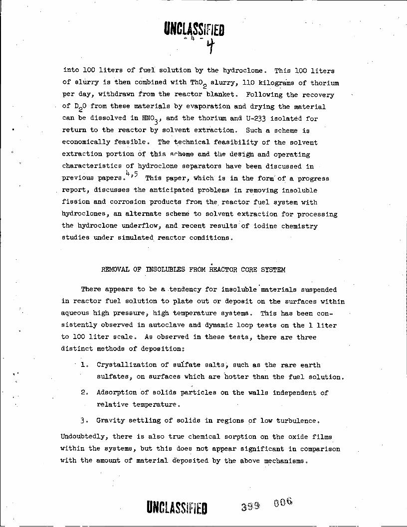
into 100 liters of fuel solution by the hydroclone. This 100 liters
of slurry is then combined with Th02 slurry, 110 kilograms of thorium
per day, withdrawn from the reactor blanket. Following the recovery
of D20 from these materials by evaporation and drying the material
can be dissolved in HNO3' and the thorium and U-233 isolated for· return to the reactor by solvent extraction. Such a scheme is
economically feasible. The technical feasibility of the solvent
extraction portion 6f this Rrheme and the design and operating
characteristics of hydroclone separators have been discussed in
previous papers.4,5 This paper, which is in the form'of a progress
report, discusses the anticipated problems in removing insoluble
fission and corrosion products from the, reactor fuel system with
hydroclones, an alternate scheme to solvent extraction for processing
the hydroclone underflow, and. recent results of iodine chemistry
studies under simulated reactor conditions.
.
REMOVAL OF INSOLUBLES FROM REACTOR CORE SYSTEM
There appears to be a .tendency for insoluble materials suspended
in reactor fuel solution to plate out or deposit on the surfaces within
aqueous high pressure, high temperature systems. This has been con-
sistently observed in autoclave and dynamic loop tests on the 1 liter
to 100 liter scale. As observed in these tests, there are three
distinct methods of deposition:
1. Crystallization of sulfate salts, such as the rare earth,.
sulfates, on surfaces which are hotter than the fuel solution.
2. Adsorption of solids particles on the walls independent of
relative temperature.
3. Gravity settling of solids in regions of low turbulence.
Undoubtedly, there is also true chemical sorption on the oxide films
within the systems, but this does not appear significant in comparison
with the amount of material deposited by the above mechanisms.
UNCLASSIFIEB 359 006

UNCLASSIFIEB-5 -
In autoclave tests, the rare earth sulfate precipitates did
not deposit on surfaces at the same temperature or slightly cooler
than the solution. Well formed crystals of rare earth sulfates grew
on metal surfaces hotter than the solution containing the rare earths.
In these same tests iron and chromium oxides were observed to collect*
on the surfaces with an even distribution independent of relative
temperature.
In small loops, about 5 liters in size, equipped with a hydroclone
and underflow pot and which contained no large stagnant regions, about
15% of precipitated rare earth sulfates were recovered in the hydroclone
underflow and essentially all the remaining insoluble rare earths were
deposited on externally heated surfaces within the loop. In these tests
the equilibrium amount of rare earths in solution in the loop corresponded
roughly to the solubility at the temperature of the heated wall. In these
same tests, 50 to 85% of Zr02' a typical insoluble corrosion product oxide,
formed by hydrolysis of Zr(S04)2 inside the loop was recovered in the
hydroclone underflow with the remaining Zr02 rather evenly distributed
about the loop.
Further tests were carried out in two larger loops. One, the HRT
mock-up, was constructed of full scale Homogeneous Reactor Test (5 MW
prototype of a two-region homogeneous reactor) components except for a
much smaller heat exchanger and no reactor vessel (see Fig. 2). This
loop had a capacity of 80 liters, the solution was circulated at 400 gpm,
and the flow through the hydroclone was 2 liters per minute. The other
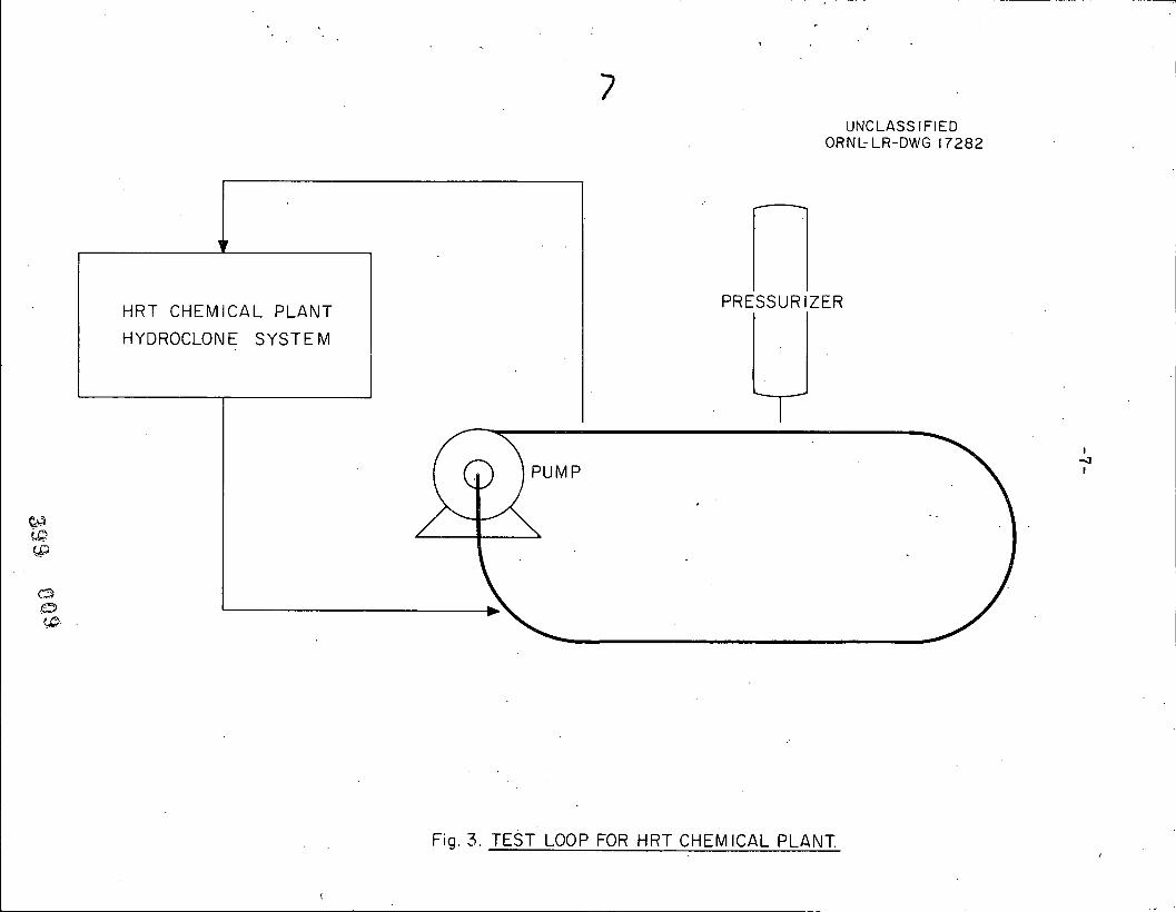
loop had the same circulation rate and contained 30 liters of solution,
' but was a simple loop of pipe with no horizontal stagnant regions (seeFig. 3)· The hydroclone circuit for this loop was the actual HRT Chemical
Plant (see next section). The flow through the hydroclone in this case
was 3 liters per minute. The tests were conducted by injecting into
these loops under simulated reactor conditions a mixture of Fe203'
Cr203 and Zr02 expected to be formed by corrosion in the core system of
a thorium breeder reactor. The experiments were carried out with and
without the hydroclone operating.
UNCLASSIFIE9399
007

1
'.
F
UNCLASSIFIEDORNb LR-DWG (4813-A
PRESSURIZERr-1 CLONE.V • II GAS SEPARATOR
0 1
HEAT
5EXCHANGER X
(40
0004. 0
DUMP TANK
Fig.2. HRT MOCK-UP SCHEMATIC
1
7UNCLASSIFIED
ORNLLR-DWG 17282
--.
V
PRESSURIZERHRT CHEMICAL PLANTHYDROCLONE SYSTEM
PUMP -3
eCeop
00 D.(P.
Fig. 3. TEST LOOP FOR HRT CHEMICAL PLANT

Concentration factor, as used here means the concentration of solids in
(INGUiSIFIED
When the hydroclone was not operated, the simulated fission and
corrosion products disappeared from the circulating stream of the HRT
mock-up with a half-period of 2.5 hr (see Fig. 4). When the hydroclone
was in operation, the half-period was 1.2 hr. From these results it
was concluded that the half-period for solids removal by the hydroclone
alone was 2.3 hr and that the hydroclone efficiency was about 20%. In
the simpler loop, without the hydroclone operating the half-period for
the disappearance of simulated fission and corrooion products was 11 hr,
and with the chemical plant hydroclone operating, 1 hr. The chemical
plant efficiency for solids removal as calculated from these results
was 25%. This is in close agreement with the mock-up results.
In the above tests using a 0.4 in. hydroclone at 250 to 300'C with
pressure drops of 15 psi or greater across the hydroclone, concentrat ionfactors*,of from 70 to greater than 1000 were obtained for the simulated
corrosion products. For the removal of solids from the core system of a
two-region reactor a concentration factor of 30 is adequate. Based on
these data, the performance of the hydroclone as a solids concentrator
appears entirely satisfactory for this application.
The difference in solids behavior in the two loops is partially
due to collection of solids in the non-turbulent horizontal pressurizer
header of the mock-up. A large deposit of solids was found, apparently
settled out by gravity, in this horizontal run of pipe after the runs
were completed. No stagnant regions were present in the simple loop.
However, this loop had a smaller surface area in contact with the
solution than the mock-up and further experiments will be required to·
· differentiate between adsorption of solids and gravity settling.
A concentrated solution of mixed rare earth sulfates traced with
Ndl47 was also injected into the HRT mock-up. Of the rare earths that
precipitated in the loop, as determined by the tracer method, about 75%
were removed by the hydroclone. The hydroclone concentration factor
observed for the rare earth sulfates was greater than 100 in this test.
In this case the heat exchanger represented a hot spot in the loop since
the underflow receiver compared to the solids concentration in thehydroclone feed.
UNCLASSIFIEO 399 010

-9--
UNCLASSIFIEDORNL-LR-DWG 17283
® WITHOUT HYDROCLONE OPERATING.-.
400 (T,/2=2.5 HOURS)
TE<[w ® HYDROCLONE OPERATING
(T,2,4-2 HOURS)
CDZ
M f
Cr
0LUIO» 40Z
Z9 A
.HZE»ZLUO BZ
8
E-1000 1.0 1 ' 1 1 ' 1 1 1
0 4 8 12 16 20
TIME AFTER SOLIDS INJECTION (HOURS)
Fig. 4. BEHAVIOR OF SOLIDS IN THE HRT MOCKUP
399 011

UNCLASSIFIED- 10 -
'....
the loop was heated by high pressure steam on the water side of the
exchanger. The missing. precipitated rare earths were not located, but
from experience with the smaller systems they.collected on the heated
surface. In the reactor, the only surface expected to be hotter than
the fuel solution is the core tank which will be exposed to intense
gamma and neutron heating. However; in in-pile loops there is no
tendency for insolubles. to depos it on materials exposed to intense
radiation, and for this reason no appreciable deposition of rare earths
or corrosion products is expected in the high flux region of the reactor.
In none of the mock=up tests was any evidence found that the solids
accumulated in the low pressure system. There were indications that
lowering the system temperature to room temperature and then returning
to operating conditions resuspended a large fraction of the material
deposited in the high pressure system.
From these experiments, it was concluded that future aqueous homo-
geneous reactors must be designed to eliminate regions of low flow rate
in horizontal runs of pipe which can trap solids by sedimentation. Even
in properly designed reactors there will be a significant accumulation
of solids in the system by solids adsorbing on the materials of con-
struction, but this may be expected to reach an equilibrium where the
solids will flake off as rapidly as they deposit. Further experiments
are required to establish whether this accumulation of solids will be
sufficient to .interfere with heat transfer and fluid flow in the reactor
system. These studies are planned for the dynamic loop and in the HRT
Chemical Plant which is described in the next section.
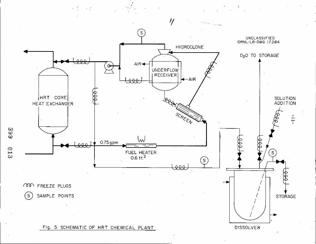
HRT CHEMICAL PLANT
6The HRT is a 5 MW prototype of a two-region homogeneous reactor.
The core system will contain about 500 liters of fuel solution. The
HRT Chemical Plant has been installed as a by-pass around the reactor
heat exchanger (see Fig. 5). The major components of the chemical
plant are a heater to compensate for heat losses, a screen to protect
UNCLASSIFIED„099 012
1
.1
Iq
UNCLASSIFIED
4 1 HYDROCLON
ORNL-LR-DWG 17284
D20 TO STORAGEC M IL' A» 'IR. 1
UNDERFLOW
RECEIVERILQ.Q.QJ 1
<B-AIR
HRT CORE SOLUTIONHEAT EXCHANGER ADDITION
\3 4SCREEN +.5 «/ l»,1(0 1
4 'An-Al v 0.75gpm FUEL HEATER 9 1 02 0.6 ft.2 A 4 / 1 -
I liL' 1 V // , F '4, 1<7-91 FREEZE PLUGS V SAMPLE POINTS / STORAGE
1
1
1 -+
Fig. 5. SCHEMATIC OF HRT CHEMICAL PLANT DISSOLVER

UNCLASSIFIEB- 12 -
the hydroclone from plugging, the hydroclone with a 2.5 gal underflow
receiver, and a canned rotor pump to supply the pressure drop across
the hydroclone. This system is designed to operate at 300'C under
2000 psi lolal prewBure. The flow througn the hydroclone will be
3 liters per minute, so that one reactor volume will pass through/
the hydroclone every 3 hr. Once a week the chemical plant will be
valved off from the reactor, the contents cooled, and dropped to a
tantalum lined vessel. From this vessel the D20 will be recovered
by evaporation and the residue sampled after dissolution in 10.8 M H2SO4·.4
This will permit accurate determination of the fission and corrosion
products removed from the reactor by the hydroclone.
The process equipment is contained in a concrete cell 21 ft deep,
12 ft wide and 24 ft long (see Fig. 6A). This cell is separated from
the reactor by 5 ft of heavy concrete and from the operating ar'eas by4 ft of heavy concrete, The cell is lined with 3/4 in. steel plate,
and is designed to withstand an internal pressure of 50 psig with
essentially no leakage to the atmosphere. This is sufficient to
contain the reactor contents in case of a rupture of the high pressure
equipment. The top closure is made by a welded membrane in between
the two sets of roof plugs that form the top shield.
The plant is designed so that the pump, heater, screen, and
hydroclone can be easily replaced by underwater maintenance procedures.
The hydroclone is contained in a flange mounted on the 2-1/2 gal
underflow receiver. The heater and pump are also flanged into the
system. The hydroclone is 0.4 in. internal diameter, 1.5 in. long
and lined with titanium to resist abrasion (see Fig. 6), A similar
hydroclone was operated on a 300'C loop for 4000 hr with no significant
erosion taking place. The pump is a Westinghouse canned rotor pumpdesign for 300'C, 2000 psi operation, and will deliver 1 gpm at 100 ft
of head with a 60 cycle power supply. A variable frequency power
supply for this pump is used to control the flow rate through the
hydroclone circuit.
The equipment is connected in such a manner that when valved off
UNCLASSIFIED399 014

-13-
-*d . il,1 „: 'f
1, , H
a I
.. 2.-1%
: , - 1--48:.,
I
L · : 7 / ,.&--1 '...:y/
.. 4. lf,. , t= 4
. 7:/*-- -.- :f/...1-, -' 4 3
.
": #rb.... **t
/9931.... i. .5 ./ 4. I ' .,, 1./6
9/ .4 /. 1 11/ ...
'1 ...I:....9 '4-
A_fl / ./ I7 -I. . . . , - 0'9
'... · "•'.·' ·" , 3:. '..,',· · '. 7 '·
1,/0 '.:. ,= 'I -
31,.
4. 1 4 ':.,= *..."f','.·'. - * 1*11-1-
./.I. i
I.-,1115* "N
-'
,
,». - -k I ar::
*,
1 /'.....1,;,1
i» . . .2't....
, I f / :I'l -,l. 4 .. .. .
1-/ I ...10 , - ..1.-1-- / 6 ..t. /1.4= 11, ti+ 1 F/ . i .*.4
, . '
I..fi 11
,/..11 1. 3..4 /21 -i- .-2, ,
- '141 - 4. 4 . ./ ..i'.t·'f ,;.-/ ,...
... :1'.3,w* 1,-' '6· . i.. ....'.7( . 1 1 , ..,2..'-i; /. ....14, . 4 ., .2 . " 4
I ..,r. ' .11'Id 1' ' 1E. 3
& $ 1
- 1 ./. ... . .a .i r.,4..pra f :...'lin
.'E '151 -Al
91 I - ../4
,
, *' .L» -
*. .£2 2 -€
1,% » 20 - / « . /
399 015Fig. 6A HR'l' Chemical Plant High Pressure Cell

-14-
UNCLASSIFIEDORNL-LR-DWG 17287
01 04
/: j
.
iI.* <.- HEAD
' 11\ 7
1
\ 1 i\
CONTAINER
/1 --- FLANGE
,
6 - LEAK DETECTOR\
UPPER CLONE GASKET
LOWER CLONE GASKETVORTEX FINDER
CLONE BODY
CLONE RETAINER
399 016
FIG. 6. CROSS SECTION OF INTEGRALLY FLANGED HYDROCLONE.

UNCLASSIFIED- 15 -
from the. reactor the pump can be used to circulate the underflow
receiver contents over the screen to flush off any large particles
and through the heater to dissolve any rare earth sulfates that may
have accumulated on the heated surface. A sampler is provided. to
sample the underflow receiver contents and the hydroclone overflow.
The core solution fed to the hydroclone is sampled in the reactor
circuit.
The underflow receiver temperature is controlled by a circulating
stream of heated air. The mechanical valves used in the plant are
pneumatically operated, bellow sealed and are backed up with freeze
plugs to eliminate leakage. The freeze plugs are made by coiling
stainless steel tubing, through which a refrigerant can be passed
around the pipe. In many lines freeze plugs alone are used. This is
possible where the line can be frozen with no liquid flowing through
it. It was not found possible to freeze lines through which more than
5 ml/min of solution was flowing.
The plant is designed to demonstrate the proposed core process
only up through heavy water recovery. The dissolution of insolubles in
H2SO4 is intended only as an analytical method. In actual processing
of a reactor, the uranium and soluble fission products need only be
leached from the insolubles with HNO since laboratory tests indicate
only 0.1% of the uranium in the underflow receiver contents was HNO3
insoluble.
The program planned for this plant is aimed at establishing the
feasibility of removing insolubles from the reactor fuel system with
hydroclones and obtaining data on the chemistry of fission and corrosion
products under actual reactor conditions.
URANIUM RECOVERY BY PEROXIDE PRECIPITATION
For an isolated reactor or small reactor station, a considerable
savings could be effected by a simple, cheap clean=up of the uranium
from the hydroclone underflow. In such a situation the irradiated Th 2
UNCLASSIFIEO399 017

UNCLASSIFIED- 16 -
from the blanket would be packaged in shielded containers and shipped
to a central solvent extraction plant for processing. Peroxide
precipitation is one attractive method for recovering the uranium
from the hydroclone underflow sufficiently decontaminated for return
to the reactor.
This method consists of removing, by centrifugation and washing0
at room temperature, the insoluble fission and corrosion products
such as the oxides of Zr, Fe, Cr and Nb; selective precipitation of
uranium aS U04 from the supernatant, thermal decomposition of the U04
in a dilute solution of D2SO4 to provide a suitable fuel solution for
return to the reactor core (see Fig. 7).
The precipitation of U04 under simulated process conditions was
tested on a laboratory scale (see Fig. 8). In these tests it was shown
that 99·9% of the uranium could be recovered with a separation factor
of greater than 10 from nickel, rare earths, and alkali metals. The
U04 precipitate was easily converted to a UO2SO4 solution by thermal
decomposition in the presence of stoichiometric H2SO4 in the form of
dilute H2S04"
CHEMISTRY OF IODINE
Studies of the chemistry of iodine under simulated reactor
conditions have been carried out in autoclaves and a dynamic loop.7
At 300'C with an oxygen atmosphere it was found that at equilibrium
about 85% of the iodine in 0.02 E UO2SO4 solution was present as the
elemental form, and that the distribution coefficient for elemental
iodine between the vapor and liquid phase was 7 on a mole fraction
basis. The remaining 15% of the iodine was in the iodate form.
Experiments carried out under Co60 gamma irradiation at 250'C
indicated that radiation tends to shift the equilibrium in favor
of the elemental form. Addition of simulated reactor corrosion and
fission products, other than ruthenium, had no detectable effect on
the iodine valence distribution or volatility. At a concentration
UNCLASSIFIED399 018

17UNCLASSIFIED
ORNL-LR-DWG 17285
PEROXIDE DILUTE D2504
V VHYDROCLONE U02504 IN020,Ni,Cs, i l.104UNDERFLOW D CENTRIFUGE M U04 PRECIPITATION
CENTRIFUGE DISSOLUTION
RARE EARTHS\
&-
U02504 IN 020% tr FSLURRY OF 111 4
04 INSOLUBLESD2093
u T
REACTORCORE
0».6 I EVAPORATOR 1(0
VSOLIDS
Fig. 7. UNDERFLOW PROCESSING BY U04 PRECIPITATION.

-18-UNCLASSIFIED
ORNL-LR-DWG 1728610.0
STARTING SOLUTION:40 g/1 U02S04-0.IM H2S04- 0.35M Ni S04(0.03 g/1 corresponds to. a U loss of 0.1%.)
1.0.-.L
• 01)-
\01 PRECIPITATION WITH.-I PRECIPITATION WITH Na202» H202 (0.5M excess)
ai<IZa..
0.4Z
MEDZ<OLD
0.04
Of)CH ' ' ' ' 'l l'l l0.5 0.7 0.9 4.1 4.3 1.5 1.7 1.9 2.1 2.3 2.5 2.7 2.9 3.1
PH
Fig. 8. SOLUBILITY OF U04 vs pH399 020

NCLA SSIFiE1- 19 -.---
five times that expected in the reactor, ruthenium fixed essentially
all the iodine in the liquid phase. However, this was partially
off-set by the presence of hydrogen gas and gamma radiation. From
these data it was concluded that iodine will be sufficiently volatile
to be removed from the reactor by gas stripping at elevated temperature.
4 This was confirmed in the absence of radiation by dynamic loop tests in*
which iodine, injected into the system as either iodide or iodate, was
effectively removed by gas (02 and water vapor) stripping at 250'C.
In an actual reactor this stripping may be accomplished in two
ways. If sufficient copper sulfate catalyst is added to recombine all
the radiolytic gas as it is formed, the iodine can be stripped in a
high pressure system using oxygen as the stripping gas.3 If, however,
some radiolytic gas is allowed to form in the reactor, this gas will
serve to strip I, Xe and Kr from the reactor fuel solution.
One proposed method of removing I, Xe and Kr from such a radiolytic
gas stream is to let the gas down to atmospheric pressure, separate out
entrained fuel solution, and recombine the D2 and 02 catalytically. Xe
and Kr would emerge as noncondensables along with excess 02 when the
water. vapor from the recombiner is condensed at 65'C. -However, experi-
mental data indicate that iodine would be in the condensate since the
vapor-liquid distribution coefficient for iodine under these conditions(
is only 0.01 on a mole fraction basis.''
Some of the iodine will also follow the entrained fuel solution
to the dump tank from the entrainment separator. Under the conditions
of the entrainment separator and dump tank (these contain fuel solution
at 100'C and one atmosphere of pressure), elemental iodine has a mole
9. fraction distribution coefficient of 0.2. Under these conditions the
effect of radiation is to reduce iodine to the iodide which is non-
volatile. Therefore, the bulk of iodine may show up in either the
reactor dump tank or the condensate from the recombiner condenser,
depending on how rapidly valence state reduction and mass transfer
takes place as the temperature of the letdown stream is lowered.
Present data indicate that the condensate would contain the bulk of
UNCLASSIFIEB 399 021

UNCLASSIFIEB=20 -·1-
the iodine. Isolation of iodine from such a water stream by distil-
lation should be practicable. Separation from the reactor fuel in
the dump tank probably would require fixation on silver„ The actual
distribution of iodine between these two portions of the HRT system
will be studied before a means of final isolation of the iodine is
developed.
REFERENCES
1. Briggs, R. B. and Swartout, Jo A., "Aqueous Homogeneous Power' Reactors," Proceedings of the International Conference on the
Peaceful Uses of Atomic Energy, Geneva, 1955, Vol. III, Session ·12A, United Nations, New York (1956).
2. Ferguson, D. E., "The Processing of Aqueous Homogeneous ReactorFuel," Process Chemistry, Vol. I, p 249, Pergamon Press Ltd. (1956) .
3. Bruce,F.R., "Chemical Processing of Two Region Thermal BreederReactors," Chemical Engineering Process, Vol. 52, P 347 (Sept., 1956) .
4. Gresky, A. T., "Separation of U233 and Thorium from Fission Productsby Solvent Extraction," Process Chemistry, Vol. I, p 212, PergamonPress Ltd. (1956).
5. Nurmi, E. 0. , et al., "Hydraulic Cyclone Study for Liquid-SolidSeparation,",meeting, American Nuclear Society, Chicago, Illinois(June, 1956).
6. Beall, S. E..and Swartout, J. A., "The Homogeneous Reactor Test,"4 Proceedings of the International Conference on the Peaceful Uses.of
Atomic Energy, Geneva, 1955, Vol. III, Session 13A, United Nations,New York (1956).
7. McNees,R.A., "Chemical Behavior of Some Fission and CorrosionProducts in Aqueous Uranyl Sulfate at High Temperatures," meeting,American Nuclear Society, Chicago, Illinois (June, 1956).
P
UNCLASSIFIE 399e22

0-7-0
1*
\
A
A.6.
S.
. 4
, :9