opera radar site selection and protection
TRANSCRIPT

OPERA III
Work package 1.5a Part B
“Weather radar site selection and protection”
Final Report
OPERA deliverable OPERA_2010_04
Ferenc Dombai Meteorological Service of Hungary
April, 2010

I INTRODUCTION 3 Work package 1,5a – part B 3 Problem area 5 II COMPREHENSIVE SUMMARY 7
A.) Operator / Institute 7 B.) Site selection methods 8 C.) Site protection - without RLAN 10 D.) Mitigation the degradation of data quality 11
III OVERVIEW OF THE ANSWERS 13
A.) Operator / Institute 13 B.) Site selection methods 15 C.) Site protection - without RLAN 25 D.) Mitigation the degradation of data quality 32 E .) Radar sites sheets 39
IV BEST PRACTICES 48 V OUTLOOK 51 VI RELATED PUBLICATIONS 54
2

I INTRODUCTION
Work package 1.5a - part B
The goal of the work of WP1.5a is to deliver an Inventory of weather radar noise sources
and methods for treating them throughout all OPERA countries in Europe. This inventory contains the collection of European expertise on the impacts of various disturbances such as wind turbines, jamming transmitters, buildings and other structures, and how such disturbances can be minimized, either through pre-emptive administrative management – site selection and policy, or through signal/data analysis.
For optimal use of OPERA resources the task of the WP1.5 was divided in two main parts. The DeBuilt OPERA meeting decided that all tasks concerning the jamming transmitters will be carried out, completed and documented by the IMGW team as WP1.5a – Part A . This team has a task to maintain closer contact and cooperation with EUMETFREQ for reaching more effective protection of weather radar bands and share the information on the OPERA community. Other tasks of the problem area and the preparation and completion of the inventory was to be carried out by the HMS team. Thus the site selection problem, reflections from new structures of urban development, beam blockage, occultation corrections are the problem areas of Inventory WP1.5a – Part B, presented in this document. In the Dublin Opera meeting the content of Inventory was further fixed as follows: active noise sources eg. jamming transmitters, RLAN and frequency protection are included (belong to part A), but the natural noise sources are not the targets of this inventory. The meeting also decided that the wind turbine problem must be referred only in the Inventory because this problem area was managed by OPERA2
In the preparation phase of WP1.5a – Part B (Inventory on the European sources of expertise on radar site selection and site protection problems) an enormous amount of documents was searched using keywords – radar site, sitting of radar, beam blocking, occultation, clutter map, clutter rejection, etc - working documents, deliverables, papers and presentations from COST 72, COST 73, COST 75, COST 717, GORN , OPERA 1, OPERA 2, BALTEX, ERAD 2000, 2002, 2004, 2006, 2008. In the following paragraphs we summarize the findings.
We found only a very small number of scientific documents dealing with radar site selection and site protection problems, and no legislative rules were found on the protection of weather radar site supporting long term reliable measurement. Only weather radars operated by armies or by air traffic control organizations have site protection but these are mostly realized in indirect ways. It means that general rules are valid for safeguarding military estates, air navigation equipment sites and airports but there are no specific issues for weather radars.
In reaching the clear sky above and around weather radars efforts are focused on the site selection preparation works. Using high resolution digital terrain and urban area models with combination of beam propagation models in GIS programs or specific programs (EUROCONTROL SACC, Radio Mobile or own developments Planner) make it possible to find optimum places for our radars. The good quality clutter rejection methods – Doppler or polarization or combination methods – dynamic occultation corrections and vertical profile corrections are the typical procedures for treating the passive artificial noise source impacts.
3

Task 1 - Definition of content of inventory The content of PART B was defined at the Dublin meeting and it was refined at other OPERA meetings afterwards. Due to the lack of legislative rules on weather radar site protection, the site selection practice was included in this inventory as a “proactive site protection method”. The present content was compiled to correspond to these. Task 2 - Questionnaire The survey of European efforts on PART B topics were done via searching the available publications and documents of different European programs, campaigns, conferences, and workshops. For a more reliable survey on legislative rules and practices of weather radar site protection a questionnaire was compiled and distributed among OPERA members. Due to the low response rate, a second turn was organized in 2010. This inventory contains these answers as the main body of the document. Task 3 - Outlook for the world The survey done on the course of PART B work examined several papers dealing with the same problem area outside of Europe. Some interesting works are referred to in this document. Task 4 - Best practices To compensate the lack of information on the weather site protection practices many European papers dealing with site selection problems were taken into account on the course of PART B work. This inventory provides a short survey of some excellent works describing procedures to reach better quality radar data. Task 5 - Compiling the Inventory The first version of this Inventory was compiled by October 2009. The Inventory was recompiled after the second turn including new answers on the questionnaire and taking into account the remarks made by WG1 group at OPERA Toulouse meeting. This draft document was finalized in April 2010. Others Although the HMS was not addressed to make special works for the Part A subpackage some activities were done. The output of the Hungarian study on DFS effectiveness and the developed RLAN filtering methods are proposed to be included in the final document of WP1.5a – Part A.
4

Problem area
The objective of OPERA is to harmonize and improve the operational exchange of weather radar information between National Meteorological Services. In order to fulfill this objective a consistent set of data of agreed quality has to be exchanged. Current radar systems vary in their standards of operation and, therefore, information on the quality of the exchanged radar data is of crucial importance.
The location where a radar station is placed is selected upon many different criteria such as logistic aspects, observation quality for a specified target of users and local political considerations also. A site can be selected in a way to maximize the coverage of a given territory where a network of radar stations exists or to best observe a predefined region for the identification of hydrometeorological risks. Finding a suitable location for weather radar in mountainous or urban areas is rather painstaking. (from WD 05 /02 )
Siting a radar is a task in which many different points need to be taken into account which have effect on the decision. Usually several issues have to be considered simultaneously. The radar horizon should be unobscured up to the extent possible determined by the local orography. If the surrounding country is flat it is necessary to find a location so that no (or very tiny) blocked sectors exist and so that the location is not too far from the optimal location based on the network planning. In mountainous regions such locations have to be found on mountain tops. The unobscured horizon is only one of the things that determine the radar location. The location also affects the building cost of the radar, if the site is not accessible in easy way. A remote location also increases the cost of electricity lines and the computer connections. It will also increase the cost of maintenance trips and will lengthen the delay of starting the maintenance
The first measure of the quality of a radar site is a so called occultation map showing the limiting range or lowest usable elevation as a function of range. The height of the antenna feed (above the surface) is an important parameter as well: It determines both the coverage of the radar and the quality of the precipitation estimates. At low elevations, radar beams can be blocked, partially or totally, by orography or human-made obstacles. The blocking, if not accounted for, introduces errors in the radar reflectivity estimates. A half beam blocking results in an underestimation of 3 dBZ. Occultation can be avoided by using sufficiently high elevation angles, or corrected via a predefined polar map of occultation factors. The presence of permanent clutter and the probability of anomalous propagation clutter are also important factors.
Several permissions are needed for the building and operation of the radar. Most notable are the building permission from the local authority, transmitting license from the frequency authority and the permission from the authority responsible for the radiation safety. The local communities also have a say in the acceptance because the radar tower may be a disturbing feature as part of the scenery or the radar is not wanted in the surroundings because of radiation safety issues. The future building around the radar site has to be discussed with the local authority and explain that obscuring buildings, masts etc. decrease the value of the radar
The quality of single-site radar products can be enhanced in several ways. Data cells with bad quality tags can be assigned with interpolated values from adjacent good quality data, domain
5

regions without radar measurements can be filled out by extrapolation, data fields can be smoothed to eliminate various artifacts, and data values can be adjusted using radar-independent measurements.
Vertical extrapolation - Due to the Earth curvature or orography and in region shadowed by building structures it is not always possible to measure precipitation close to the ground. In these cases the surface rainfall can only be estimated from the measurements aloft. Significant under or over estimations can be produced if the precipitation is assumed to be constant with height. Low-level precipitation can be extrapolated from the upper-level measurement by taking into account the vertical reflectivity profile. Real-time measured profiles close to the radar, climatological profiles, or simplified synthetic profiles can be used. The use of reflectivity profiles is far from the best method to improve the quality of surface rainfall estimates under non-optimal conditions.
Spatial interpolation or blockage correction - Some data cells in a radar polar data field or in a Cartesian product can be tagged as containing data of a bad quality. These quality tags, produced by preceding quality control procedures, reflect problems related to operational malfunctioning, occultation, attenuation, aliasing, and clutter. The tagged data cells can be assigned with new values interpolated from the adjacent good-quality cells. The interpolation in polar data fields is performed radially or tangentially, and in Cartesian products horizontally or vertically.
Others, smoothing - After the spatial interpolation, radar data fields can still exhibit various artifacts: non-recognized clutter speckles, radial sectors of heavy attenuation behind strong convective cells, radial irradiations from other radars, circular rings in echo top or precipitation accumulation products due to discrete scanning angles, etc. These artifacts introduce sharp gradients in otherwise smooth weather fields and can be eliminated, to some extent, by a suitable texture smoothing. However, the smoothing process effects weather data as well, resulting in a loss of fine-scale details.
Clutter signal can be suppressed to a large extent from the reflectivity and radial wind
data by reducing the echo power around zero radial velocity using discrete filtering techniques in the time or frequency domains. All operational Doppler radars apply some kind of filtering before the radial velocity is determined.. High-pass filter on linear signals: In signal processors utilizing PPP, high pass filtering is applied on I and Q time series to filter out low frequencies attributed to clutter. Difference between the total and filtered echo power, both estimated from the linear channel data, is used to correct the logarithmic channel reflectivity. Zero-velocity channel blocking: In signal processors utilizing FFT, echo power from the zero-velocity channel is blocked and interpolated from adjacent channels. Clutter contamination is thus effectively removed without weakening the weather echo
6

II COMPREHENSIVE SUMMARY
The main part of the task of WP 1.5a-B part was making a survey on site selection and
protection practices among the EUMETNET/OPERA countries using. This content was agreed at OPERA meetings and it was compiled and circulated in the first half of 2009 via the FTP site of OPERA. This questionnaire was accessible in online form managed by IMGW in this period also. The B part questionnaire was only answered by 7 countries from the 29 OPERA member countries before deadline. Because of this low ratio - about 25 % - a second turn was organized continuing this survey in the first quarter of 2010. In this period another 9 countries sent in their replies. Altogether 16 countries, more then half of the OPERA member countries sent answers for our questioner in this survey.
In this working document the answers are presented in two ways in order to make it easier to derive findings or comparisons on different practices. At first we provide a comprehensive summary and after we provide the answers in edited forms grouping together the same topics answered by different countries.
In the answers there was no mention of any rules or laws considering the protection of existing radar sites except UK where weather radar sites are registered by MoD’s Defence Estates and UK Met Office has right to object to planning applications via MoD DE. This “missing rules” situation can be generalized for all countries where weather radars are operated with civilian meteorological and/or hydrological institutions and it is understandable if we are looking on the very different supervising organizations schemas of the meteorological services in different countries.
A: Operator / Institute
The questionnaire was answered by 16 countries (17 institutions) of OPERA. All answering institutions are radar network operators. Among these there are 11 institutes that are active only in the field of meteorology (Royal Meteorological Institute of Belgium, Cyprus Meteorological Service, National Meteorological Service- Italy Finnish Meteorological Institute, Meteorological Service of France, Hungarian Meteorological Service, KNMI – Netherland, Norwegian Meteorological Institut, National Meteorological Administration-Romania, Federal Office of Meteorology and Climatology - Swtzerland, MetOffice - UK), 4 institutes are also active in the field of hydrology (Czech Hydrometeorological Institute, Meteorological and Hydrological Service- Croatia, Instituto de Meteorologia - Portugal, Hydrometeorological Service of Serbia ). The only country where weather radars are operated by an aeronautical organization is AustroControl - Austria. Considering the supervising organizations it can be stated that in almost all countries a kind of supervising system exist - ministries of environment, transport and communication, research and education, science and technology , environment and water, home affairs, agriculture and natural resources.
7

Most of the answering institutions are civilian organizations but in two countries –weather radar operators are supervised by the ministry of Defense – Italy and United Kingdom. Considering the site protection issues this heterogeneous situation makes for difficulties in organizing harmonized actions in the EC to achieve common rules for the long time protection of weather radar sites because of the different distances from the legislators in different countries.
B: Site selection methods B1. Procedures
All countries provided sufficiently informative answers moreover 9 answers were well detailed covering different steps of site selection. The UK answer was so detailed that it was necessary to summarize much more than the others. The original UK answer and other answers are available on the OPERA FTP site: An important statement can be derived from the answers: there are no commonly used methods in OPERA countries and no OPERA WD is referred to in this respect. The goal of the site selection procedures is to find the optimum site fulfilling many different requirements. The typical scheme of the site selection procedure is as follows:
- select a region where new a radar site is needed for better coverage of territory - preselect some candidate sites in that region using topographic and/or local maps - study the beam propagation and the lowest achievable altitude map using a digital terrain
model and/or calculation of radio horizon using digital model of relief and standard radio refraction.
- evaluate the local infrastructure (property, access road, electricity, communication lines,..) and possible conflicts (environment, radio compatibility, obstacles,..)
- visit the site and evaluate of local obstacles by visual observations/theodolite (trees, building,..) and facilities
- consult with the local authority, clarify the property rights, specific rules of permissions, etc.
- consult with national frequency authorities for EMI and for permission of band use - calculate the safety distances using maximum allowable exposures of radiation - compile the decision making material with options for 2 or 3 sites containing the results of
above mentioned actions
As the main preselection step many countries use digital topography maps (GTOPO30 / SRTM30) for calculating the radar coverage maps. There was no mention of specific GIS tools or applications helping the site selection procedures to find the optimum site but some answers indicated their use in an implicit way.
The important criterion of safety distances using maximum exposures accordingly to the Directive 2004/40/EC was mentioned only by 6 countries but its application can be assumed for all countries.
8

B2. Listing laws and rules considering radar site
In the answers general and local authority building regulations, rules for getting “permission for use of new structures”, and the environmental protection rules with listing specific environmentally protected areas were mentioned typically as rules or laws, that must be considered in the site selection procedure. Additionally, there is a need to have a permission from the national frequency administration in all countries for operating weather radars at any specific site. The European Directive 2004/40/EC on allowable radiation exposures was mentioned in some answers only.
No specific EC or national regulations dealing with weather radar implementation were
mentioned. The internationally harmonized rules for using frequency bands were not directly referred to but national frequency authorities were mentioned in some answers. It means that generally we do not deal with such questions frequently. B3. Methods for calculating partial beam blockage or occultation map:
Only 6 countries are using a method for calculating partial beam blockage or occultation map. Belgium is using “Simulation of the effective coverage” by Wessels. In the CzechRepublic an occultation map is calculated and in Romania the native NEXRAD Precipitation Processing System is used with embedded beam blockage correction. The UK is using dynamically created Probability of Detection (PoD) files at the beginning of each month for creating occultation maps. Other two countries Netherlands and Norway are using theodolites to get information on the radio horizon and later they compile tables for occultations. B4 GIS, digital terrain models and software for site selection
Digital terrain model or digital maps were mentioned in almost every answers. Only 4 countries Cyprus, Finland, France and Netherlands missed this topic. More frequently were mentioned the GTOPO30, SRTM30 USGS digital elevation maps. Some countries referred national digital maps as used in this procedure. There was no mention of GIS applications helping the site selection procedure directly but for managing or handling digital maps it is necessary. Only Norway and Italy SRD referred to specific software for this purpose: AREPS – Advanced Refractive Effects Prediction System. ( Space and Naval Warfare Systems Center, San Diego) and Metranet (Lassen). B5. References
Only 4 countries mentioned written references considering site protection – Belgium (Estimation of the areal coverage of radars and radar networks from radar site horizon data) Czech (Radiohorizon and Clutter Areas for Czech Weather Radar Network), Serbia (Radar Coverage Analysis in Virtual GIS Environment), Romania(The WSR-88D Rainfall Algorithm).
9

C: Site protection - without RLAN C1. Existing opportunities Most of the answers referred to consulting with the local authority as a site protection opportunity. The answer from Belgium is appropriate for the typical situation “We have to trust on the goodwill of local authorities” as a possible information source and support radar site protection. Only in three countries, in Czech Republic (30 km), in France (2 km and 10/30 km for windmills) and in U.K. there are protected areas around weather radar sites in which area it is not allowed to erect any buildings higher then radar antenna height. Some countries misunderstood this question as they referred to the physical protection of radar sites with fences, locked steel doors or by the police. C2. Rules and laws for site protection
Besides the rules dealing with general frequency allocation tables valid in every country only three countries mentioned rules, ministerial decrees, and laws dealing with radar site protection. In France after setting up a radar a ministerial decree will be issued. In Serbia the meteorological service has a right to issue its opinion about all construction plans whether it endangers its system or not . In U.K. the Met Office is a part of the Ministry of Deffence(MoD) and from this situation it comes that Met Office can object to planning applications via the MoD.
Taking into account these exceptions we can state the typical answers for this topic can be
summarized as “There is not legislative protection of weather radar sites”. It is valid for almost all answering countries. C3. Monitoring the changes in surroundings
Some countries are in a good situation. The Czech Hydrometeorological Institute is involved among the participants of building permit processes. The situation is almost the same in U.K., in Serbia, and in Norway as in these countries the meteorological services are on the list of institutions that have to be informed of new buildings. This well informed situation gives the possibility to follow the changes around radar sites. In other countries only regular visits to the radar sites gives a chance for doing that. But it is not a preventive opportunity.
Some countries, Hungary and Portugal mentioned the analysis of time series of radar data for discovering the changes in the surroundings of radar sites as they can be seen from the quality degradation of radar data. The Cyprus and Switzerland are in good position as the radar sites are in national forests or on high peeks which do not lend themselves to easy modification of the radar surroundings.
10

C4. GIS, digital terrain models and software for monitoring surroundings and used for calculation their impacts
Only two countries answered positively for this topics Switzerland and U.K. but the typical answer is “not relevant”. It means that typically there are no methods for monitoring and calculating the impact of new building structures in the surroundings of radars in almost any OPERA countries. C5. References No references were made to methods for preserving the existing radar sites. It is possible that such references are missing in all OPERA countries.
D: Mitigation the degradation of data quality D1. Methods for mitigation (new structures)
With the exception of Switzerland no methods are mentioned for mitigating the degradation of data quality caused by new objects in the surroundings of radar sites. It might be that the situation is the same in all OPERA countries. In Switzerland the employed dynamic clutter map resolves this problem. In Austria the “shortening of the trees” methods was mentioned but its is supposed to be the general methods in OPERA countries. D2. Clutter filtering
Many countries failed to cover this topic but it is supposed that they are using clutter filtering if they are using Doppler radars. Other 11 countries answered positively and some of them gave some details about clutter filtering. The typically used clutter filtering method is Doppler FFT filtering. In Portugal this methods is combined with several data quality thresholds. In U.K. The clutter indicator fields are used for this purpose. D3. Beam blockage
Generally speaking there are not any methods used for mitigation the degradation of data quality caused by beam blockage of new objects in surroundings of radar sites in most of the answering countries. Only Czech Republic, Romania, Switzerland and U.K. are using beam blockage correction methods. D4. Vertical profile correction
Generally speaking there are not any methods used for mitigating the degradation of data quality using vertical profile correction in most of the answering countries. Only Czech Republic, Netherlands, Switzerland and U.K. use vertical profile correction.
11

D5. Others correcting methods
Typical answer is no answer but Netherlands and Portugal stated that they are using some other mitigation method. Only Portugal describes a point clutter filtering method for filtering the speckles. D6. In compositing
About half the answering countries skipped this topic. Two countries definitely stated that they are not making national composites Croatia and Serbia. In the compositing processes the maximum values are used in Austria, Czech Republic, Hungary, Romania and the average values in Italy. In Netherlands the range weighted mosaicing scheme and in UK the Probability of Detection files are using for compositing weather radar data. D7. References:
There was not mentioned any references describing methods for mitigation the degradation of data quality caused by beam blockage of new objects in surroundings of radar sites except Switzerland. In Switzerland there is an online documentation describing the procedures used for this purpose. The title is Operational Use of Radar for Precipitation Measurements in Switzerland.
http://www.meteosvizzera.admin.ch/web/de/wetter/aktuelles_wetter/radarbild/radar-
informationen.Related.0001.DownloadFile.tmp/onlinedocumentation.pdf
12

III OVERVIEW OF THE ANSWERS
A: Operator / Institute AUSTRIA Austrocontrol / Aviation / Rudolf Kaltenböck Date: 17 February 2010 / Rudolf Kaltenböck Supervising org: Federal Minister for Transport, Innovation and Technology BELGIUM Royal Meteorological Institute of Belgium / civil meteorology / Laurent Delobbe Date: 10 April 2009 / Laurent Delobbe and Geert De Sadelaer Supervising org: no answered CZECH REPUBLIC Czech Hydrometeorological Institute / civil meteorology and hydrology / Petr Novák Date: 14 May 2009 / Petr Havránek, Jan Kráčmar, Petr Novák Supervising org: Ministry of Environment CROATIA Meteorological and Hydrological Service/ civil meteorology and hydrology / Bojan Lipovscak Date 27 January 2010 Supervising org: CYPRUS Cyprus Meteorological Service / civil meteorology / P. Georgiou, D. Charalambous Date: 20 February, 2010 / Demetris Charalambous Supervising org: Ministry of Agriculture, Natural Resources and Environment FINLAND Finnish Meteorological Institute / civil meteorology / Asko Huuskonen Date: 14 April 2009 / Asko Huuskonen Supervising org : Ministry of Transport And Communications FRANCE National Met Service of France / civil meteorology /Jean Luc Cheze Date: 11 February 2010 / Jean Luc Cheze Supervising org : Ministry of Education Energy and Development HUNGARY Hungarian Meteorological Service / civil meteorology / Ferenc Dombai Date: 26 March. 2009 / Ferenc Dombai Supervising org : Ministry For Environment and Water
13

ITALY National Meteorological Service / military / Antonio Vocino Date: 27 May 2009 / Antonio Vocino Supervising org: Ministry Of Defence ITALY - SRD Agenzia Regionale Per La Protezione Dell’ambiente Della Sardegna – ARPAS / civil meteorology and hydrology / Roberto Pinna Nossai Date: 20 May 2009 / Giacomo Cavalli Supervising Org: Assessorato Difesa Ambiente Regione Autonoma Sardegna NETHERLANDS KNMI / civil meteorology / Hans Beekhuis Date 13 February 2010 / Hans Beekhuis Supervising org : Ministry of Traffic V&W NORWAY Norwegian Meteorological Institute / civil meteorology / Morten Salomonsen Date: 04. January 2009 / Trygve Aas Supervising org: Ministry of Education and Research PORTUGAL Instituto de Meteorologia, I.P./ civil meteorology and hydrology / Sérgio Barbosa Date:30 July 2009 / Paulo Pinto and Sérgio Barbosa Supervising org: Ministry of Science, Technology and Higher Education ROMANIA National Meteorological Administration / civil meteorology / Sorin Burcea Date: 8. May 2009 / Sorin Burcea Supervising org : Ministry For Environment SERBIA Hydrometeorological Service of Serbia / civil meteorology and hydrology / Julijana Nadj Date: . .2010 / Julijana Nadj Supervising org : Government SWITZERLAND Federal Office of Meteorology and Climatology MeteoSwiss / civil meteorology and hydrology / Marco Boscacci Date: 22. March,.2010 / Marco Boscacci Supervising org: Federal Department of Home Affairs, FDHA UNITED KINGDOM U K Meteorological Office,/ military / Elizabeth Kyte Date 14th May 2009 / Rebecca Miles / Gordon Hutchinson/ Roger Carter / Selena Georgiou Supervising org: Ministry of Defence, MoD
14

Site selection methods B1. Describe shortly the site selection procedures AUSTRIA
- Select region where new radar site is needed for better coverage of territory (check lowest elevation coverage of existing radar site
- Change of existing radar site (increase of antenna height, moving of site location) - Select several locations highest in their neighborhood - Calculate the “floor” - lowest achievable altitude map using digital elevation map - Preselect more than 1 location for site survey close to infrastructure (electricity power
line, roads…) - Visit the preselected sites and make reports containing – site surveys, clearing the
property rights, drafting budgeting, consultancy with local authority, etc. - Calculate the safety distances using maximum exposures accordingly to the European
Directive (EC, EN) and ÖNORM BELGIUM
Important criteria concerning the site selection and height of the tower construction are: - the local topography of the surrounding landscape - nearby buildings with special attention to high and massive constructions - local vegetation, trees - high voltage lines - windmills and windmill farms - nearby transmitters - sea clutter possibility
CZECH REPUBLIC
- Candidate positions preselected by topographic map (areas of local elevation maxima) - Use of digital model of relief: remapping of elevation data from GTOPO30/SRTM30 (by
USGS) into polar coordinates centered at candidate radar site - target resolution of 1 km x 0.5 deg., up to the range of about 250 km
- Completion of the polar model using dense datasets (SRTM3 and/or local model) for close areas – resolution 0.25 km x 0.5 deg. in polar coords, up to the range of 50-60 km from candidate radar site – depending on local topography
- Calculation of radio horizon using digital model of relief and standard radio refraction – for each 0.5 deg. azimuth ray, maximum elevation angle [0.05 deg.] and range of the most important obstacle [km] is found (similar to COST-73 procedure)
- Evaluation of local obstacles by visual observations/theodolite (trees, buildings etc.) – refinement of radio horizon (azimuth x elevation data)
- Calculation of radar coverage (for 1500m above terrain, 3km above MSL = COST-73 and NEXRAD criteria)
- Evaluation of local infrastructure (property, access road, electricity, communication lines, possible conflicts [environment, radio compatibility, obstacles, ..]
15

CROATIA
Select region where new radar site is needed for better coverage of territory. Select several locations highest in their neighborhood with about 50-60 km
- Preselect 3-5 locations for site survey close to electricity power line and roads with solid surface using analog or digital maps with high res. 1:10 000 or 1:25 000 (military maps)
- Visit the preselected sites and making reports containing – site surveys, clearing the property rights, drafting budgeting, consultancy with local authority, etc.
- Calculate the safety distances using maximum exposures accordingly to the Directive 2004/40/EC
- Radar coverage of the area, distance between radars cca. 150 km. - Existence of the infrastructure – roads, electricity, IT connections - Ownership of the land particle - Compiling a decision making material – with options for 2- or 3 sites
CYPRUS
Isolated location to avoid incommensurate reaction from local residents Communication and electricity facilities Location owned by Government is preferable (to reduce cost)
FINLAND
A number of suitable candidate locations are selected for closer study by studying maps. In the study the horizon is considered, as well as the ease of getting the road, electricity and telecommunications at the spot. Field excursion is made to the sites and negotiations with the land owner started for the best candidate(s)
FRANCE No answer ITALY
- Select region where new radar site is planned to improve the coverage of territory. - Select areas where a military site is located (preferably air-force, but also other military
sites are eligible). - For each potential site, study the beam propagation and the lowest achievable altitude
map using digital terrain model. - For pre-selected sites, perform a feasibility study involving the authorities for EM
compatibility, energy supply and legal aspects. - NOTE: Because of the exclusive property (State property) of the sites, there are
advantages, in general, as regards the management of the sites. - Visit the pre-selected sites and produce a final report (with 3 or 4 options) for the
decision making process. ITALY - SRD
- Select region where new radar site is needed for better coverage of territory. - Preselect 2-3 locations for site survey close to electricity power line and roads with
solid surface.
16

- Visit the preselected sites and making reports containing – site surveys, clearing the property rights, drafting budgeting, consultancy with local authority, etc.
FRANCE No answer HUNGARY
- Select region where new radar site is needed for better coverage of territory. - Select several locations highest in their neighborhood with about 50-60 km - Calculate the “floor” - lowest achievable altitude map using digital elevation map
(using GTOPO30 or SRTM3 and own program) for the selected locations - Preselect 3-5 locations for site survey close to electricity power line and roads with
solid surface using analog or digital maps with high res. 1:10 000 or 1:25 000 (military maps)
- Visit the preselected sites and making reports containing – site surveys, clearing the property rights, drafting budgeting, consultancy with local authority, etc.
- Calculate the safety distances using maximum exposures accordingly to the Directive 2004/40/EC
- Compile a decision making material – with options for 2 or 3 sites NETHERLANDS
There are no general rules here, we look for the most advantageous site, keeping in mind that in area’s that are indicated as national park or areas that are highly habituated are difficult to get admission to allow a radar, due to general regulations, and the allowed level of HF transmission)
NORWAY
Norway is a mountainous country with lot of areas without any infrastructure. To stay within a limited budget we have to be very careful. 1. As a starting point we look at the existing radar network (March 2009: 7 operational radars). We accept a distance of 220 – 280 km between the radars. With the known distance, we look for sites with as little blockage as possible towards the sea and with existing infrastructure (roads, electricity e g).
PORTUGAL
Location regarding major built up areas and major airports; coverage of drainage basins; maximization of radar horizon and site surveys.
ROMANIA
- Select region where new radar site is needed for better coverage of territory. - Select several locations highest in their neighborhood with about 50-60 km (taking into
account the possible expansion of the city, growing trees in young forests) - Calculate the “floor” - lowest achievable altitude map using digital elevation map
(using GTOPO30 or SRTM3 and own program) for the selected locations (using presetted scan strategy, elevations, VCP)
- Preselect 3-5 locations for site survey close to electricity power line and roads with solid surface using analog or digital maps with high res. 1:10 000 or 1:25 000 (military maps)
17

- Visit the preselected sites and making reports containing – site surveys, clearing the property rights, drafting budgeting, consultancy with local authority, etc.
- Calculate the safety distances using maximum exposures accordingly to the Directive 2004/40/EC
- Compile a decision making material – with options for 2 or 3 sites
SERBIA Adding a new weather radar site is subject to the following steps:
- Select a region where new radar site is needed according to the existing radar coverage of Republic of Serbia territory for the non Doppler, Doppler and Doppler radar with dual polarization, separately.
- Analyze the military maps to find few peak elevation candidates for suitable radar sites taking into considerations roads to the sites, power lines, neighborhoods, environments, etc.
- Generate the radar coverage diagrams for all relevant heights from the lowest achievable altitude to the highest in the 1000 m steps using digital 3D geographical information system (GIS) and our own software package for generating the radar coverage diagrams.
- Calculate radar coverage effectiveness of the proposed radar sites alone and its effectiveness in the whole network
- After detailed analysis of radar coverage diagrams and their matching with existing radar network diagrams, the expert team visits the preselected sites and, after that, makes final decision about site location and report including: site surveys, safety distances according to the Directive 2004/40/EC, clearing the property rights, drafting budgeting, consultancy with local authority, getting building permissions, etc.
SWITZERLAND
- Select region where new radar site is needed for better coverage of territory. - Select a few locations, typically on mountain tops, satisfying minimum conditions:
-Relatively free from other civil or military installations. -computed radar visibility from a digital terrain model sufficient in the most important
sectors (limited mountain shielding) -availability of power line and telecommunication -site accessible at least by cable car
- Visit the preselected sites and making reports containing – site surveys, clearing the property rights, consultancy with local authority, etc.
- Compiling a decision making material – with options for 1 or 2 sites
UNITED KINGDOM Where a new site is required, possible locations are investigated. Possible sites are then assessed for the risks likely to be encountered due to Planning issues. Out of these selected locations an assessment is made for suitability of the site. Site assessment is done via a GIS based review process (desktop) followed by site inspection. In assessing the suitability of a site, considerations will include: visible horizon, proximity of any obstructions (buildings, windfarms, trees etc.). A site will be selected if sufficient suitable coverage can be obtained. Note that the position of obstructions relative to the
18

radar site are key – it is more acceptable to accept degraded quality due to obstructions that lie between the radar and an area of little or no population than it is to accept degraded quality in the direction of a major conurbation or ‘quick catchment’
B2. Listing the laws, ministerial decrees, local authority orders or other rules etc. to be considered in the site selection AUSTRIA
-General rules and acts for building a new structures and getting permissions for use -Rules of local government for building a new structures and getting permissions for use
environmental protection rules -Directive EN, EC and ÖNORM for allowable radiation exposures
BELGIUM
No specific laws or regulations are applicable. General building regulations have to been taken into account, also aviations regulations in case of nearby airports or buildings higher than 44m.
CZECH REPUBLIC CROATIA
- General rules and acts for building a new structures and getting permissions for use - Rules of local government for building a new structures and getting permissions for use - Environmental protection rules
CYPRUS
Construction License from local authorities Bandwidth ownership and emission license from the national telecommunications authority
FINLAND
Difficult to list the laws, decrees etc, but the following permissions are needed: - building permission from the local community - permission from the national frequency administration, radiation safety administration and aviation administration.
FRANCE No answer HUNGARY
- General rules and acts for building a new structures and getting permissions for use - Rules of local government for building a new structures and getting permissions for use - Environmental protection rules and (protected areas – NATURA 2000) - Directive 2004/40/EC for allowable radiation exposures
ITALY
- Directive 2004/40/EC for allowable radiation exposures (as adopted by national law – DLGS n. 257/07 – on November 2007, in force since 30/04/2008).
19

- Specific regional and local environmental protection rules.
ITALY - SRD - General rules and acts for building a new structures and getting permissions for use - Rules of local government for building a new structures and getting permissions for use - Environmental protection rules
NETHERLANDS
Sorry there are a lot of regulations but I’m not familiar with them NORWAY
We need building permission from local authorities. If the area in any way is protected we need governmental permission. We also ask NRA for permission to use the special frequency and we notify the Norwegian Radiation Protection Authority.
PRTUGAL
Environmental protection rules. ROMANIA
- General rules and acts for building a new structures and getting permissions for use - Rules of local government for building a new structures and getting permissions for use - Environmental protection rules and (protected areas – NATURA 2000) - Directive 2004/40/EC for allowable radiation exposures
SERBIA
- General rules and acts for building a new structures and getting permissions for use - Rules of local government for building new structures and getting permissions for use - Environmental protection rules and - Directive 2004/40/EC for allowable radiation exposures
SWITZERLAND
- General rules and acts for building new structures and getting permissions for use - Rules of local government for building new structures and getting permissions for use - Clearance from federal office of telecommunication - Environmental protection rules - Directive 2004/40/EC for allowable radiation exposures
UNITED KINGDOM
All sites will be subject to standard planning applications under The Town and Country planning (Environment Impact Assessment)(amendment)(England) regulations 2008 (No2093 and associated Scottish and Welsh Laws. All sites must work within the planning law as defined by the County and Local authorities. Radiation surveys are often required as a condition of planning approval. Applications to transmit on the relevant frequencies have to be submitted to the Office of Communications (OFCOM) via a MOD Radio Site Clearance Application.
20

B3. Describe shortly methods for calculating partial beam blockage or occultation map, etc AUSTRIA BELGIUM
Simulation of the effective coverage using the method proposed by Wessels (1990). CZECH REPUBLIC
Occultation map is calculated from digital model of relief (in polar coords. 1 / resp.0.25 km x 0.5 deg steps, as a side product of radio horizon calculation (see item 2 above)
CROATIA HMS are not using beam blockage correction CYPRUS Not applicable FINLAND
Not needed, because a site with no beam blockage is sought for and is possible to find in Finland. We have used a lifting device at a prospective place and measured the horizon at the level of the radar antenna. Before that a thorough study using maps is made.
FRANCE No answer HUNGARY HMS are not using beam blockage correction ITALY Beam blockage correction is not operational. ITALY - SRD There is not used beam blockage correction. NETHERLANDS
Every 5 years or so we scan the horizon with a theodolite. The results of this visual scan are transferred to a table of occultations. In cases of low stratiform rain we can recognize the occultations too, so this serves as a feedback on the table.
NORWAY
In the chosen area we have two – three sites we want to check out. At the sites we use a theodolite to measure the horizon to find the blockage
PORTUGAL Not applied ROMANIA Beam blockage correction used by the Precipitation Processing System SERBIA Beam blockage correction is not used in HMSS weather radar network
21

SWITZERLAND - Compute rough the visibility for 0, 1 and 2 degree elevation with commercial software - Beam blockage correction is not used
UNITED KINGDOM
Probability of Detection (PoD) images are dynamically created at the beginning of each month using the available Frequency of Detection (FoD) files. These show permanent and semipermanent beam blockages at each site, and are used to dynamically detect small regions of occultation. The larger green regions of beam blockage are derived using an occultation algorithm. This makes use of available horizon data derived from an engineering survey, in addition to the FoD files.
(See more in the attached “UK Answer for WP1.5“) B4. Listing the used digital terrain model, map and GIS or other specific software in site selection procedure AUSTRIA
GTOPO30 and SRTM3 digital elevation maps used by ZAMG BELGIUM
Digital terrain model provided by the National Geographic Institute of Belgium CZECH REPUBLIC
- USGS data sources: GTOPO30, SRTM30, SRTM3 - Software: in-house
CROATIA
In house developed application CYPRUS No answer FINLAND - None FRANCE No answer HUNGARY GTOPO30 and SRTM3 digital elevation maps ITALY
A local version of a digital terrain model is used to evaluate a-priori the beam propagation for site selection
ITALY - SRD There is not used any digital terrain model and GIS software. Metranet, by Eldes Lassen International, is the specific software used for radar management.
22
NETHERLANDS We do not apply a digital terrain map. NORWAY
1 We use an old MSDOS software which includes an unknown map database. 2. AREPS – Advanced Refractive Effects Prediction System. ( Space and Naval Warfare Systems Center, San Diego). This software use DTED level 1 or 2. (Digital Terrain Elevation Data
PORTUGAL
military charts and other geodetical documents (future system site was selected using a digital elevation map).
ROMANIA GTOPO30 and SRTM3 digital elevation maps SERBIA
IORP software package developed for radar sites selecting and 3D digital maps with very high resolution
SWITZERLAND
- Swiss DHM25 digital elevation model UNITED KINGDOM GIS based software/ tools have previously been utilized in the site selection procedure, including:
NI_ORDNANCE_SURVEY.RASTER_50km_NI GB_ORDNANCE_SURVEY.RASTER_50k WORLD_MISC.UK_CGIAR_ALTITUDE_DTM_90m
B5. References BELGIUM
Wessels, H.R.A., 1990. Estimation of the areal coverage of radars and radar networks from radar site horizon data, in Weather Radar Networking seminar on COST Project 73, Edited by C.G. Collier and M. Chapuis, pp. 204-211, Kluwer Academic Publishers, Dordrecht.
CZECH REPUBLIC - Kráčmar, J. : Radiohorizon and Cluuter Areas for Czech Weather Radar Network (in
Czech). Meteorological Bulletin (Meteorologické zprávy), 1994, vol. 47, 163-171. CYPRUS No answer FRANCE No answer FINLAND None
23
HUNGARY There is not any written reference ITALY There is not any written reference. ITALY- SRD There is not any written reference. NETHERLANDS Not referenced NORWAY No answer PORTUGAL There is not any written reference ROMANIA Fulton et al., 1998, The WSR-88D Rainfall Algorithm. Wea. Forecasting, 13, 377-395 SERBIA
Kostić A., Rančić D.: Radar Coverage Analysis in Virtual GIS Environment, 6th International Conference on Telecommunications in Modern Satellite, Cable and Broadcasting Services-TELSIKS 2003, Nis.
SWITZERLAND None UNITED KINGDOM None
24

B: Site protection - without RLAN C1. Describe shortly the existing site protection opportunities AUSTRIA
Consultancy with local government BELGIUM
The main concern is the erection of new windmills near the radar site location. The RMI is not contacted for any building permission of high constructions. We have to trust on the goodwill of local authorities to send us information about these kinds of projects. We are also in contact with a regional working group who advises concerning windmill farms. Aviation authorities have to give advice and will contact us, this is only in case of buildings near airports or other aviation related constructions (beacons).
CZECH REPUBLIC
Protected area (up to about 30 km, for areas with elevation higher than radar antenna), with construction restrictions, is maintained by local Office for construction (stavební úřad)
CROATIA No answer CYPRUS Fence and locks. Occasional inspection from maintenance crew and police FINLAND No answer FRANCE
Around each radar, a protection area of 2 km radius is set-up to avoid any obstacle to be build-up (no building or other obstacle can be authorized within this 2 km radius above a certain height (typically set well below the radar emission) without the specific visa of Meteo France. For the specific case of Wind-farms, protection areas (exclusion distance up to 10 km and coordination distance up to 30 km) consistent with the OPERA Recommendation are applied, although not fixed by law and as such, not always followed by local authorities.
HUNGARY Consultancy with local government or with investors of new building structures ITALY
In case of detection of disturbances, investigations by local authorities of Ministry for Economic Development can be required, in order to identify the source of disturbances and evaluate the possible solutions
25

ITALY – SRD Consultancy with local government, corporations, societies, or with investors/companies of new building structures or radio installations.
NETHERLANDS No answer NORWAY
All our radars are concrete towers with locked steel doors. A local person inspect the site regularly There is remote infrastructure monitoring of: 1.Temperature 2.Voltage 3.Communication 4.Door alarm 5.Fire alarm
PORTUGAL
There is not any protection of civilian weather radar sites ROMANIA Consultancy with local government or with investors of new building structures SERBIA Consultancy with local government or with investors of new building structures SWITZERLAND None UNITED KINGDOM
Met Office is part of the Ministry of Defence(MoD) and therefore comes under the MoD’s Defence Estates when it comes to safeguarding. These are detailed on the MoD sites database. In this database each site is defined on a map showing the area of interest and requiring the relevant authority to inform MoD DE (so Met Office) of proposed developments. If there is due cause, Met Office can object to planning applications via MoD DE. In addition to the above, Met Office is informed of most windfarm developments within the UK as voluntary site assessment exists for Windfarm developers running jointly between MoD DE, the Civil Aviation Authority (CAA) and the wind farm developers association (British Wind Energy Association (BWEA))
(See more in the attached “UK Answer for WP1.5“) C2. Listing the laws, ministerial decrees, local authority orders or other rules etc. providing protection for existing radar sites AUSTRIA
Weather radars in Austria are aeronautical instruments BELGIUM
No specific laws are applicable
26

CZECH REPUBLIC - Czech Republic Law No. 127/2005 on Electronic Communications. CROATIA
Regulations about frequency usage. CYPRUS No answer FINLAND
The legislation does not provide much protection. The board of the local community has a key role here. They give building permissions, and can protect our measuring sites, if they see it important. We have not had any problems until now. Most of our radars are at places where building hardly will be a problem
FRANCE
The protection area of 2 km radius is specified by the Law on a general basis and is, for each radar, set-up by a ministerial decree (after Public consultation). For the specific case of Wind-farms, the protection areas are set-up by a inter-ministerial circular, asking to local authorities to follow the Meteo France requirements, except in very exceptional cases. This circular is unfortunately not binding the local authorities and, in addition, having no regulatory status, can lead to Court actions from Wind-farms operators.
HUNGARY There is not any legal protection of civilian weather radar sites. ITALY
There is not any legal protection of military weather radar sites, because the frequency range does not lie in the range of exclusive frequencies reserved for military use
ITALY – SRD
There is not any legal protection of civilian weather radar sites. NETHERLANDS
KNMI tired to make appointments with local authorities on alarming us in case of building plans, but this never worked out fine. Of course building plans get published but we don’t actively scan these publications
NORWAY
There are no legal regulations PORTUGAL No answer ROMANIA There is not any legal protection of civilian weather radar sites
27

SERBIA According to the Law on construction planning (”Official Gazette” of the Republic of Serbia 72/09) for each construction RHMS issues its opinion whether it endangers the functioning of the Service (meteorological and hydrological measuring, radar observation)
SWITZERLAND
None, only recommendation when planning new wind farms UNITED KINGDOM
The only formal legal process is the planning permission, which is subject to standard planning applications under the Town and Country Planning (Environment Impact Assessment) (amendment) (England) Regulations 2008 (No.2093) and associated Scottish and Welsh Laws.
(See more in the attached “UK Answer for WP1.5“) C3. Describe shortly methods for monitoring the changes in surroundings arising from urban and rural developments and causing degradation of data quality at existing radar sites AUSTRIA
- feedback of forecasters and maintenance staff - monthly/yearly radar data analysis
BELGIUM No specific monitoring. CZECH REPUBLIC
the Czech Hydrometeorological Institute is involved among the participants of building permit process on all prepared projects of objects with abnormal height in distance up to 30 km from the both Czech radars. It is not too difficult due to terrain configuration in the vicinity of radar sites.
CROATIA Not answered CYPRUS
Radar site is surrounded by the national forest where no development is allowed. The site remains the same since the installation of the RADAR in 1996
FINLAND
Regular visits to site. News in media giving insight into future developments FRANCE No answer HUNGARY There is not any method. Occasionally discovered in long term radar data analysis ITALY There is not any method. Only discovered by analysis of the time series of radar data.
28

ITALY – SRD There is not any method. NETHERLANDS
Every 5 years or so we scan the horizon with a theodolite. The results of this visual scan are transferred to a table of occultations. In cases of low stratiform rain we can recognize the occultations too, so this serves as a feedback on the table.
NORWAY
All our radars are built far out in the wilderness where the only change in the surroundings might be windmills. Before a contractor can start building windmills, he has to write a report on the consequences. In this report military radars and meteorological radars must be included. Meteorological Institute is on the mailing list when the report is sent out for comments and we refer to the OPERA II WP1.8 Impact of “Wind Turbines on Weather Radars” if we expect trouble. The local inspector will report any changes or plan for changes around the site. The contract with the landowner state that we should be notified for any changes around the site
PORTUGAL
the changes in surroundings causing degradation of data quality at existing sites are found in long term radar data evaluation
ROMANIA There is not any method. SERBIA
There is not any method SWITZERLAND
All sites are on mountain tops, so generally no changes in the surroundings arise. The only potential problem is caused by the building of windmills on other mountain tops.
UNITED KINGDOM
There is a requirement for the database of applications to be kept up to date, with those that have failed or been withdrawn are removed; this is an ambition for MoD DE but is still yet to be fully developed
(See more in the attached “UK Answer for WP1.5“) C4. Listing the used digital terrain model, map and GIS or other specific software used by monitoring radar site surroundings and used for calculation their impacts on radar measurements AUSTRIA Not relevant BELGIUM No answer
29
CZECH REPUBLIC No answer CROATIA No answer CYPRUS No answer FRANCE No answer FINLAND None HUNGARY Not relevant ITALY None ITALY – SRD Not relevant. NETHERLANDS We do not apply a digital terrain map, as this is not a necessity in the
Netherlands. NORWAY None PORTUGAL No answer ROMANIA Not relevant SERBIA Not relevant. SWITZERLAND RITAF digital elevation model UNITED KINGDOM
AA Autoroute is used as a basic system to determine the distance of developments from the radar locations. A more detailed analysis is made on ARCGIS using the following layer fields:
NI_ORDNANCE_SURVEY.RASTER_50km_NI GB_ORDNANCE_SURVEY.RASTER_50k WORLD_MISC.UK_CGIAR_ALTITUDE_DTM_90m
(See more in the attached “UK Answer for WP1.5“) C5. References BELGIUM No answer CZECH REPUBLIC It is not any to be mentioned CYPRUS No answer FINLAND No answer FRANCE No answer HUNGARY There is not any written reference
30

ITALY There is not any written reference ITALY – SRD There is not any written reference NETHERLANDS None NORWAY No answer PORTUGAL There is not any written reference ROMANIA There is not any written reference SERBIA There is not any written reference SWITZERLAND None UNITED KINGDOM No answer
31

C: Mitigation the degradation of data quality D1. Describe shortly methods for mitigation the degradation of data quality caused by new objects in surroundings of radar sites AUSTRIA Shorten of trees in the surrounding BELGIUM No answer CZECH REPUBLIC No answer CROATIA No answer CYPRUS No answer FINLAND No answer FRANCE No answer HUNGARY There is not any specific procedure for such purposes ITALY There is not any specific procedure for such purposes ITALY - SRD There is not any specific procedure for such purposes NETHERLANDS No answer NORWAY No answer PORTUGAL No answer ROMANIA There is not any specific procedure for such purposes SERBIA There is not any specific procedure for such purposes SWITZERLAND The dynamic map in the Swiss algorithm clutter suppression resolves almost all the problems. UNITED KINGDOM D2. Clutter filtering AUSTRIA - EEC Doppler pulse pair or FFT
32

- use of additional multiparameter / multitemporal clutter filter BELGIUM No answer CZECH REPUBLIC Doppler filters (time of frequency domain CROATIA Doppler facilities CYPRUS No answer FINLAND No answer FRANCE No answer HUNGARY EEC Doppler pulse pair or FFT up to 40 dB ITALY Doppler filter (for Doppler radar systems). Local implementation of a statistical algorithm for dynamic clutter removal ITALY – SRD Velocity clutter filter. NETHERLANDS Applied NORWAY Clutter correction PORTUGAL
Based on dynamical Doppler filtering (FFT) and enhanced by the combined use of several data quality threshold parameters (LOG, CSR, SQI and SIG meaning Log threshold, clutter to signal ratio, signal quality index and weather signal power).
ROMANIA SERBIA
Sixteen 3-pole Doppler filters with 30dB, 40dB and 50dB stopband attenuation and filter ripple 0.85dB
SWITZERLAND UNITED KINGDOM
The radar software includes clutter indicator fields. These are used for in the processing in order to remove returns that are not thought to be due to meteorology
D2. Beam blockage correction AUSTRIA Not relevant
33
BELGIUM No answer CZECH REPUBLIC Applied to some product CROATIA No answer CYPRUS No answer FRANCE No answer FINLAND No answer HUNGARY Not used ITALY Not used ITALY – SRD Not used NETHERLANDS NORWAY No answer PORTUGAL No answer ROMANIA Used in Precipitation Processing SERBIA Not used SWITZERLAND The visibility map is set to 0 where persistent clutter or interference are frequent. UNITED KINGDOM
Probability of Detection (PoD) images are dynamically created at the beginning of each month using the available frequency of detection (FoD) files. These show permanent and semipermanent beam blockages at each site. This information is used to generate occultation corrections and to determine where beams need to interpolated or infilled with data from higher elevations or possibly, with data from adjacent radars.
(See more in the attachment – UK) D3. Vertical profile correction AUSTRIA Not relevant BELGIUM No answer CZECH REPUBLIC applied to some product
34

CROATIA No answer CYPRUS No answer FRANCE No answer FINLAND No answer HUNGARY Not used. ITALY Not used ITAL – SRD Not used NETHERLANDS Applied for several higher buildings and windmills. NORWAY No answer PORTUGAL No answer ROMANIA Not used. SERBIA Not used SWITZERLAND None UNITED KINGDOM
The vertical profile of reflectivity (VPR) correction is applied to the data after the corrections for clutter, speckle and anomalous propagation have been applied. The lowest usable scan is used when applying the VPR correction, and if a cell has been identified as being of non-meteorological origin then the next elevation scan will be used for that cell.
D4. Other AUSTRIA Not relevant BELGIUM No answer CZECH REPUBLIC No answer CROATIA No answer CYPRUS No answer FINLAND No answer
35

FRANCE No answer HUNGARY Not used ITALY Not used ITALY- SRD Not used NETHERLANDS Applied NORWAY No answer PORTUGAL
Point Clutter filtering: applied using the autocorrelation data after the Doppler filtering. Z and V Speckle filters: applied separately for the LOG channel parameters and the linear channel parameters.
ROMANIA No answer SERBIA Not used SWITZERLAND No answer UNITED KINGDOM No answer D5. In compositing (multiple coverage) AUSTRIA Using the maximum reflectivity values in composite BELGIUM No answer CZECH REPUBLIC Using the maximum reflectivity values in composite CROATIA There is no composite in Croatia CYPRUS No answer FINLAND No answer FRANCE No answer HUNGARY Using the maximum reflectivity values in composite ITALY Using the average of reflectivity values in composite. ITALY – SRD Not used
36

NETHERLANDS We use a range weighted mosaic-ing scheme which is very effective in
reducing: - nearby clutter - beam blockage - brightband showup
NORWAY No answer ROMANIA Using the maximum reflectivity values in composite product. SERBIA We have not radar network composite SWITZERLAND None UNITED KINGDOM
In areas where there is significant beam blockage or data loss, data from an adjacent radar is used within the composite. The Probability of Detection (PoD) files render the degraded sector as ‘unavailable’
(See more in the attached “UK Answer for WP1.5“) D6. References BELGIUM No answer CZECH REPUBLIC No answer CROATIA No answer CYPRUS No answer FINLAND No answer FRANCE No answer HUNGARY There is no written reference ITALY There is no written reference ITALY - SRD There is no written reference NETHERLANDS None NORWAY No answer PORTUGAL There is no written reference
37
ROMANIA There is no written reference SERBIA No answer SWITZERLAND Swiss online radar documentation: http://www.meteosvizzera.admin.ch/web/de/wetter/aktuelles_wetter/radarbild/radar-informationen.Related.0001.DownloadFile.tmp/onlinedocumentation.pdf UNITED KINGDOM No answer
38

D: Radar site sheets CZECH REPUBLIC
Radar Location : 11718, 49,5011N, 16,7885E, 730 m Manufacturer Gematronik GmbH Type M-360 AC Installation date 1995 (UPG 2006) Type doppl. Frequency GHz 5,6525
Power 250 kW Magnetron coaxial
Pulse/PRF 0,8 us 576, 768, 1180 Hz
Antenna size 4,2 m
Beam width 0,8 grad
Gain 44 dB
Side lobes -28 dB
Center above GL 37 m
Receiver digital-GDRX
Receiver Sens. -109 dBm
Max clutter rej 40 dB
Acquisition hardware and software: Radar control processor : GDRX / RCP Product processor (Level 1): Own developed Product processor (Level 2): Own developed Compositing processor: Own developed Clutter rejection: Doppler filter. Beam blockage correction: some products, optional Vertical profile correction some products, optional Others: RLAN filter Source of disturbances with examples (RLAN, Wind Turb., Tower, Struct., others) R-LAN, trees Screening by some very high trees in forest, mostly eastern to radar site (the origin of this screening is faulty height of radar tower design). Influencing mainly precipitation estimates.
Method of mitigations for this site: Tree felling accepted by forest management.
39
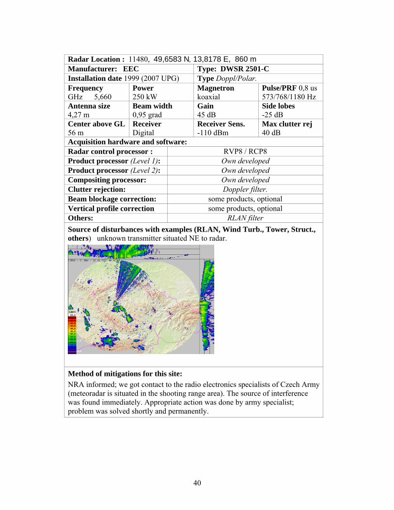
Radar Location : 11480, 49,6583 N, 13,8178 E, 860 m Manufacturer: EEC Type: DWSR 2501-C Installation date 1999 (2007 UPG) Type Doppl/Polar. Frequency GHz 5,660
Power 250 kW
Magnetron koaxial
Pulse/PRF 0,8 us 573/768/1180 Hz
Antenna size 4,27 m
Beam width 0,95 grad
Gain 45 dB
Side lobes -25 dB
Center above GL 56 m
Receiver Digital
Receiver Sens. -110 dBm
Max clutter rej 40 dB
Acquisition hardware and software: Radar control processor : RVP8 / RCP8 Product processor (Level 1): Own developed Product processor (Level 2): Own developed Compositing processor: Own developed Clutter rejection: Doppler filter. Beam blockage correction: some products, optional Vertical profile correction some products, optional Others: RLAN filter Source of disturbances with examples (RLAN, Wind Turb., Tower, Struct., others) unknown transmitter situated NE to radar.
Method of mitigations for this site: NRA informed; we got contact to the radio electronics specialists of Czech Army (meteoradar is situated in the shooting range area). The source of interference was found immediately. Appropriate action was done by army specialist; problem was solved shortly and permanently.
40

CYPRUS
Radar Location : No answer
Manufacturer EEC Type C-BAND
Installation date 1996 Type Doppl/Polar.DOPPLER
Frequency 5.60-5.68GHz
Power 250kW min
Magnetron /Klystron Magnetron
Pulse/PRF 2us/250pps
Antenna size 14ft diam
Beam width 1.0 deg
Gain 44 dB
Side lobes 25 dB
Center above GL m
Receiver Analog
Receiver Sens. -109dBm min @ 0.75MHz BW -108dBm min @ 2.0MHz BW
Max clutter rej 40dB
Acquisition hardware and software:
Radar control processor : Z80 microprocessor-based 6MHz
Product processor (Level 1): No answer
Product processor (Level 2): No answer
Compositing processor: No answer
Clutter rejection: 11-point FIR-type
Beam blockage correction: No answer
Vertical profile correction No answer
Others: No answer
Source of disturbances with examples The main existing beam blockage between 120deg and 150 deg results from a nearby peak, at almost the same altitude. Due to the altitude of the RADAR site, low clouds cannot be identified.
Method of mitigations for this site: No answer
Attached images for demonstrating: No answer
41

HUNGARY RLAN interferences at Budapest radar site
Radar Location : HU42 – 12843; ID, N47-25-46.6; E19-10-54.5; 161 m Manufacturer: EEC Type: DWSR 2500C Installation date: 1999 Doppler and dual Polar. Frequency 5.625 GHz
Power 250 kW
Magnetron coaxial
Pulse/PRF 0.8/600 us/Hz
Antenna size 4.2 m
Beam width 1 grad
Gain 45 dB
Side lobes 25 dB
Center above GL 22 m
Receiver Analog
Receiver Sens. 112 dBm
Max clutter rej 40 dB
Acquisition hardware and software Radar control processor : ESP 7 Product processor (Level 1): EDGE 5 Product processor (Level 2): EDGE 5 Compositing processor: own developed Clutter rejection: Doppler pulse pair. Beam blockage correction: No Vertical profile correction No Others: RLAN correction Source of disturbances with examples (Wind Turb., Tower, Struct., others) Continuous RLAN interferences from 12-13 sources. Typically 3-5 degree wide radial sectors with 18 - 25 dBZ reflectivity values. Method of mitigations for this site: Own developed RLAN filtering method using reflectivity and polarimetric signatures Filtering procedure a.). filter in sectors dBZ data in rays with predetermined azimuth are exchanged with interpolated dBZ data from sector borders b.). filtering random radial rays one or two bin wide dBZ rays are removed c.) filtering with ZDR remove data where – no ZDR value – ZDR value is very high > 5dB – ZDR value is very low < -6 dB In some cases the filtering near the radar equipment is too strong! The method is good to filter ground targets too!
42
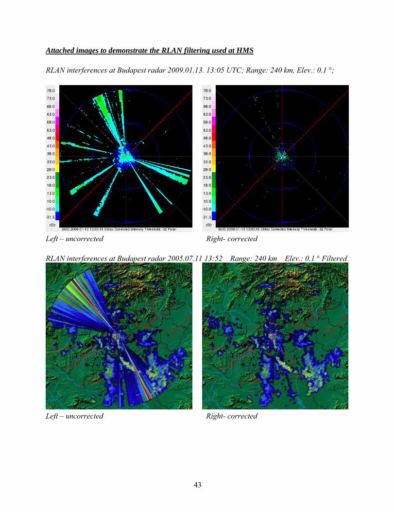
Attached images to demonstrate the RLAN filtering used at HMS RLAN interferences at Budapest radar 2009.01.13. 13:05 UTC; Range: 240 km, Elev.: 0.1 °;
Left – uncorrected Right- corrected RLAN interferences at Budapest radar 2005.07.11 13:52 Range: 240 km Elev.: 0.1 ° Filtered
Left – uncorrected Right- corrected
43

E .) Radar sites sheet NETHERLANDS
Radar Location : - NL51 WMO code - 6234 Fi = 52.954 Lambda = 4.791 heigth =50 meter
Manufacturer SELEX Type Meteor 360AC
Installation date 1996 Type Doppr.
Frequency GHz
Power 300kW peak
Magnetron Pulse/PRF 0.8 & 2 us / 250..1200 Hz
Antenna size 3.6 m
Beam width 1.0 Grad
Gain 43 dB
Side lobes -23 dB
Center above GL 50 m
Receiver digital
Receiver Sens. -115 dBm
Acquisition hardware and software: SELEX GDRX
Radar control processor : RCP
Product processor (Level 1): Abacus
Product processor (Level 2): Rainbow 5
Compositing processor: Rainbow 5
Clutter rejection: method, param.
Beam blockage correction: Rainbow 5
Vertical profile correction Radial correction
Others: ?
Source of disturbances with examples (Wind Turb., Tower, Struct., others) Wind turbine at 500m mitigated by beam blockage correction
Method of mitigations for this site: Max clutter rejection depends on the elevation. For the lowest elevation we cut out contaminated areas, for the other elevations we apply classical non-dft filtering, reaching typical values for a Doppler radar.
Attached images for demonstrating: None
44

Radar Location : NL50 WMO code - 6260 lat = 52.103 Lon = 5.179 50 heigth ==50 meter
Manufacturer SELEX Type Meteor 360AC
Installation date 1997 Type Doppr.
Frequency GHz
Power 300kW peak
Magnetron Pulse/PRF 0.8 & 2 us / 250..1200 Hz
Antenna size 3.6 m
Beam width 1.0 Grad
Gain 43 dB
Side lobes -23 dB
Center above GL 50 m
Receiver digital
Receiver Sens. -115 dBm
Acquisition hardware and software: SELEX GDRX
Radar control processor : RCP
Product processor (Level 1): Abacus
Product processor (Level 2): Rainbow 5
Compositing processor: Rainbow 5
Clutter rejection: method, param.
Beam blockage correction: Rainbow 5
Vertical profile correction Radial correction
Others: ?
Source of disturbances with examples (Wind Turb., Tower, Struct., others) Several high buildings blocking elevation 0.3 and 1.1 degrees mitigated by beam blockage correction
Method of mitigations for this site: Max clutter rejection depends on the elevation. For the lowest elevation we cut out contaminated areas, for the other elevations we apply classical non-dft filtering, reaching typical values for a Doppler radar.
Attached images for demonstrating: None
45

PORTUGAL
Radar Location :LOULLE / 08553, 37.30534N, 7.95174E, 587m Manufacturer Gematronik GMBH Type Meteor 360AC Installation date: 2003 Type Single Pol Doppler system Frequency 5.63 GHz
Power 300 kW
Magnetron coaxial
Pulse/PRF 0.8-2.0us/450-1200Hz
Antenna size 4.20 m
Beam width 1.05 grad
Gain 45.6 dB
Side lobes -28 dB
Center above GL 29 m
Receiver digital
Receiver Sens. -110 dBm
Max clutter rej 35 dB
Acquisition hardware and software: Radar control processor : RCP/VME (Gematronik) Product processor (Level 1): RVP8 Signal processor Product processor (Level 2): Software application (IRIS) Compositing processor: IRIS Clutter rejection: Doppler filtering and Data quality thresholding. Beam blockage correction: none Vertical profile correction Constant profile Others: Software filtering Source of disturbances with examples (Wind Turb., Tower, Struct., others) Several wind turbines located more than 50Km away; usual anomaly south of Faro; sometimes, it appears a radial pattern anomaly Northeast of the radar (possible RLAN) Method of mitigations for this site: Doppler filtering and data quality thresholding Attached images for demonstrate: LoopMaxzPORT.gif (both anomalies) and LoopSP.gif (RLAN?)
References
46

CROATIA
Radar Location : Fruska Gora
Manufacturer GEMATRONIK Type Meteor 500 S
Installation date 2001 Type Doppler with dual polarization.
Frequency 2.8 GHz
Power >=600 kW
Magnetron tipe Pulse/PRF 2us/250-550Hz 0.83us/250-1200Hz
Antenna size 6.1 m
Beam width 1.25 grad
Gain Min 42.3dB
Side lobes First -26dB
Center above GL 25 m
Receiver digital
Receiver Sens. 110 dBm
Max clutter rej 50 dB
Acquisition hardware and software:
Radar control processor : digital
Product processor (Level 1): ASPEN® DRX
Product processor (Level 2):
Compositing processor:
Clutter rejection: 3 pole elliptical Doppler filters
Beam blockage correction: Not used
Vertical profile correction Not used
Others:
Source of disturbances with examples (Wind Turb., Tower, Struct., others)
Method of mitigations for this site:
Attached images for demonstrating:
47

IV BEST PRACTICES IN EUROPE
ON THE CONCEPT OF THE RADAR CROSS SECTION RCS OF DISTORTING OBJECTS LIKE WIND TURBINES FOR THE WEATHER RADAR Gerhard Greving 1, Martin Malkomes 2 1 NAVCOM Consult, Ziegelstr. 43, D-71672 Marbach/Germany Z Gamic GmbH, Roermonderstr. 151, D-52072 Aachen/Germany
The performance of the weather radar (WR) can be distorted by objects located at too close distances. This is also the case for wind turbines (WT). The WR measures the amplitudes and phases of the pulse response. A widely used parameter for the evaluation of radar is the monostatic RCS. This German paper evaluates the applicability of the RCS for a single WT in this situation and proposes alternatives for the evaluation. Since the effective distortions of a WR depend also on the radar signal processing, this subject is also discussed in this work. A DECISION SUPPORT SYSTEM FOR THE OPTIMAL PLANNING OF A WEATHER RADAR NETWORK: A CASE STUDY R. Minciardi, R. Sacile, and F. Siccard CIMA, Interuniversity Research Center for Environmental Monitoring, University of Genova, Via Cadorna 7, 17100 Savona, Italy
In this work, the definition of a methodology to support the decisions entailed in the optimal WR siting in the planning of a WRN over a defined territory is presented. A methodology that allows the define the optimal planning of a weather radar network (WRN) is presented.
The decision making process needs to manage the following tasks , 1) verify the feasibility of certain configurations; 2) produce several optimal solutions; 3) modify the specifications of the parameters that characterize the formulation of the problem; and 4) analyze the sensitivity of such solutions with respect to the choice of these parameters
Several aspects affecting the planning decision, including terrain blockage, the need to measure with two Doppler weather radars in some regions, and the environmental impact of their installation are taken into account using a proper mathematical formulation. The decisional problem takes on a form that closely resembles a well-known combinatorial optimization problem, i.e., the weighted set-covering problem For each site, the covering layers have been computed taking into account the terrain blockages shown by the digital elevation model (DEM) that are met by the beam trajectories at different elevation angles of a WR positioned in that site. GIS-BASED WEATHER RADAR SITING PROCEDURE IN MOUNTAINOUS TERRAIN Christos Domenikiotis (1), Nicolaos R. Dalezios (1), and Ioannis Faraslis (2) (1) Laboratory of Agrometeorology, Faculty of Agricultural Sciences, University of Thessaly.
48

(2) Department of Planning and Regional Development, University of Thessaly.
The site selection for the enroute radars must meet different operational requirements and a complex procedure is used to determine optimum location of weather radars. The methodological approach using GIS technology was developed for selection the optimum site for weather radars to be used for hail suppression project in the mountainous region of Epirus, Northwestern Greece. The model implemented in the ERDAS Imagine software and could be run for different parameters. In this way, alternative sites could be identified. The methodology could be applied to other regions in Greece, in order to identify the appropriate sites for a national weather radar network.
In this GIS methodology two types of siting criteria are employed; mainly strategic or
regional criteria, and local or logistical criteria. Firstly the strategic criteria are applied in order to determine the region which is most suitable for locating weather radar. Having focused on the area of interest the base and land cover maps are prepared for examining the tactical criteria. The use of the tactical criteria implemented one by one result in binary maps which are overlaid to produce the final zones in GIS environment. The digitized contour data are used to build the Digital Terrain Model (DTM, raster image) and produce the three- dimensional visualization of the evaluated area. The potential sites for the weather radar installation are identified on this three-dimensional DTM. CONSIDERATIONS FOR THE OPTIMUM LOCATION OF A C-BAND WEATHER RADAR IN THE ATHENS AREA E. A. BALTAS AND M. A. MIMIKOU Department of Water Resources Hydraulic & Maritime Engineering, National Technical University of Athens, 5, IroonPolytechniou 157 80 Athens, Greece Proceedings of ERAD (2002): 348–351
For the optimum placing of weather radars in the area of Attika the software ArcView of ESRI was used. ArcView gives you the ability to visualize, explore, query, and analyze data geographically. With this software one can work with data, understand geographic relationships, gain insights, solve problems and achieve results for a variety of projects. For the needs of this work, two different scripts were developed. The first script named “radar cone” gives the cone of radar beam. The second script named “radar coverage” gives the radar beam coverage in the project area. The programming language Avenue supported by the ArcView software, was used to develop these scripts (GIS by ESRI, 1996). THE PROTECTION OF WEATHER RADAR NETWORKS.-THE UK EXPERIENCE Gordon Hutchinson and Rebecca Miles Met Ofiice UK, FitzRoy Road, Exeter, EX1 3PB. Proceedings of ERAD 2008 In this presentation the threats to the operational UK Weather Radar Network have been reviewed, as has the process used to manage these threats. Met Office actively protects its radar sites from physical blockages by following the MOD safeguarding procedures and with respect to electromagnetic interference, by working with OFCOM. The impact of windfarm developments
49

is examined in more detail, with possible mitigation actions listed. A recent example of the Whitelees Windfarm is provided, where Met Office worked with the windfarm developers in Scottish Power Renewables in order to relocate the Corse Hill radar so that the windfarm could go ahead whilst maintaining radar coverage over the central belt of Scotland. The recent and planned changes to the UK weather radar network are detailed with a clear emphasis on working with other organizations in order to improve upon the coverage of the network. EUROCONTROL: SASS-C SURVEILLANCE ANALYSIS SUPPORT SYSTEM FOR ATC-CENTRE
SASS-C (Surveillance Analysis Support System for ATC Centre) is a software toolbox developed by EUROCONTROL to provide standardized methods and tools for assessing the performance of Surveillance infrastructures. Now widely distributed to civil and military Air Navigation Service Providers, R&D organizations and industrial partners in most of the states of the European Civil Aviation Conference (ECAC), SASS-C is typically used for
- Monitoring the compliance of operational radar and trackers to nominal performance, and in particular those defined in the EUROCONTROL Surveillance Standard for En-Route and Major TMA.
- Supporting the periodical (daily/weekly/monthly) monitoring of the ATC Centre surveillance systems efficiency.
- Supporting air incident investigation. - Supporting the development of radar and tracking systems.
The current version is SASS-C V6.6. was released in 2009. The SASS-C is organised into
a number of complementary Modules. The Radar Coverage Module is used to draw MultiRadar coverage maps at various flight levels. This computes and draws shared radar visibilities diagrams at various flight levels. For this purpose, the theoretical line of sight of each radar is calculated, taking into account digitized terrain and elevation data (DTED). This is done by the SALADT program (Screening angle and line of sight analysis from digital terrain data). This tool computes the theoretical visibility volume of a site based only on terrain obstruction. The radio wave propagation model is the expanded earth model. SALADT uses terrain data that are regular in latitude an longitude, and currently handles two such formats: DTED and DCW DEM derived files. These data are coming from the US Geological Survey (USGS) Global 30 Arc Second Elevation Data Set (GTOPO30).
SASS-C has been developed and is owned by EUROCONTROL. Making available the SASS-C software forms the subject of a licensing arrangement, whereby EUROCONTROL grants a non-exclusive and personal, non-transferable license to the licensee to use the tool in object-code version. Licenses are granted free of charge to Civil and Military ATS organizations and to Industries providing service to these organizations of ECAC Member States.
50

V OUTLOOK
NEXRAD - METEOROLOGICAL CONSIDERATIONS USED IN PLANNING THE NETWORK D. A. Leone, R. M. EndIich, J. Petriceks, R. T. H. Collis and J. R. Porter+ SRI International, Menlo Park, CA 94025, NOAA Joint System Project Office, silver Spring, MD 20910 The NEXRAD system is providing information to the National Weather Service (NWS) of the Department of Commerce, the Federal Aviation Administration (FAA) of the Department of Transportation, and the Air Weather Service (AWS) and the Naval Oceanographic Command (NOC) of the Department of Defense (DOD). Planning the NEXRAD network has required a variety of technical skills. The SRI (called Stanford Research Institute) or played a key support role for the NEXRAD Program throughout the 1980s and 1990s, particularly in the areas of radar network design, optimal siting of individual radars, programmatic and individual National Environmental Policy Act (NEPA) compliance, project management, and site and permit acquisition support, and community outreach. A systematic and objective approach was used to optimize the siting of the individual radars forming the Next Generation Weather Radar (NEXRAD) network. Prime consideration was given to meteorological factors in conjunction with the user agencies needs and the population distribution. Other siting criteria taken into account included consideration of terrain features and local obstructions, locations of airways and civilian and military airports, electromagnetic interference, and integration of NEXRAD data into the national weather system. The methodology for selecting the network sites is described. NEXRAD / RADAR VISUALIZATION AND OCCULTATION IN 4-DIMENSIONS USING GOOGLE EARTH S. T. Shipley*, A. Peterlin and S. Cantrell, WxAnalyst LTD 25/th Conference on HPS, AMS AM, 2009. 12.1 Virtual Globes such as Google Earth and ESRI‘s ArcGIobe support dramatic user access to weather radar information in four dimensions. Radar occultation maps provide detailed spatial information in three dimensions for regions where signal returns are expected to fade due to radar beam blocking by terrain. Today‘s virtual Globes will also support animation. Advances in data services by the National Weather Service are providing radar data in formats compatible with Virtual Globes, enabling true 4-dimensional access to radar and correlative information. Virtual Globe geometry straightens out the radar beam propagation path as compared to traditional approaches which map radar beam propagation over a "flat Earth". In addition, distortions related to 2 dimensional map projections are mostly avoided when radar data are depicted in the spheroidal environment. The Virtual Globe approach utilizes radar data in its natural polar coordinate system without any additional reprocessing. However, various Virtual Globes may handle COLLADA models differently at this time, so we must proceed cautiously and test extensively. WxAnaIyst has provided free access to NEXRAD occultation patterns as a public service at http://wxazygycom/.
51

FAA - FEDERAL AVIATION ADMINISTRATION Primary/Secondary Terminal Radar Siting Handbook This documentation includes the following: Ground-based primary and secondary surveillance radars for civilian airports. Fixed, transportable and mobile primary and secondary air surveillance radars, for
defense. Radars for airport surface movement guidance and control; airport surface detection
equipment (ASDE). Ground-fixed or ground-mobile or naval interrogators for Identification Friend or Foe
(IFF). Long-range coastal radar for detection of sea surface targets or for detection of both sea
and air targets. Surveillance radars for the perimeter protection of sensitive installations or borders. FAA Airspace Issues in Wind Turbine Siting
Wind turbine projects need to clear many hurdles before they can proceed to construction. One of the most important milestones in any wind project is securing a determination from the Federal Aviation Administration (FAA) that the project does not adversely affect air traffic or radar systems. This can be a complicated and uncertain process, and many projects have run into unexpected delays. The primer below explains how anticipate and avoid some of these conflicts, and how the FAA review process works. Several case examples are presented. The FAA’s Role and Procedures The FAA has oversight of any object that could have an impact on the navigable airspace or communications/navigation technology of aviation (commercial or military) or Department of Defense (DOD) operations. The FAA requires that a Notice of Proposed Construction (Form 7460-1) be filed for any object that would extend more than 200 feet above ground level (or less in certain circumstances, for example if the object is closer than 20,000 feet to a public-use airport with a runway more than 3,200 feet long).
52

CANADA HANDBOOK FOR AIR NAVIGATION PLANNING AND OPERATIONAL REQUIREMENTS Transport Canada - responsible for transportation policies and programs. It ensures that air, marine, road and rail transportation are safe, secure, efficient and environmentally responsible. Transport Canada reports to Parliament and Canadians through the minister of Transportation, Infrastructure and Communities From the Handbook 2.2.2 Weather Radar
No structures exceeding the height of the radar antenna should be built within a radius of 300 m of weather radars. The Regional Director, Technical Services will co-ordinate the necessary approvals with Environment Canada, which is responsible for siting weather radars. Author There was not found any written reference on radar siting and site protection on WEB pages of Meteorological Service of Canada or Environment Canada. 2.2.3 General Radar Siting Criteria
a. Terrain Terrain within 1000 m of the antenna is of prime importance to the performance of the
radar system. The terrain should have either a rough surface (variations of 1 m or more) or be well covered with trees and shrubs, preferably of a coniferous variety. Terrain of this type will reduce the amount of ground reflection. Beyond 1000 m, rough or vegetated terrain, as described above, or low, small buildings (e.g., residential housing) are preferred.
b. Coverage
The Primary and Secondary Surveillance Radar Systems should be located more than 500 m from the edges of areas where large, wide-bodied aircraft are known to remain for sustained periods of time. Structures or natural growth should not block the line-of-sight from the radar to the airspace on approach to runways or to other critical airspace as identified for a particular airport by the Regional Director, Air Traffic Services.
c. Consultation
If large structures (e.g., warehouses, power lines, hangars, etc.) are to be constructed within 10 000 m of a radar, it is essential that the Technical Services Branch of the Department be consulted regarding the location, building material and orientation of the structures prior to authorization of the construction.
53

VI RELATED PUBLICATIONS
Radar Site Europe COMMON SOFTWARE LIBRARY Jacqueline Sugier Met Office OPERA Project 1e2 CONSIDERATIONS FOR THE OPTIMUM LOCATION OF A C-BAND WEATHER RADAR IN THE ATHENS AREA E. A. Baltas and M. A. Mimikou, Department of Water Resources Hydraulic & Maritime Engineering, National Technical University of Athens, DETECTION AND REMOVAL OF CLUTTER AND ANAPROP IN RADAR DATA USING A STATISTICAL SCHEME BASED ON ECHO FLUCTUATION J. Sugier1, J. Parent du Chˆatelet2, P. Roquain2, and A. Smith1 1 Radar technology centre, Met Office, 2 Direction des Syst`emes d’Observation, Meteo France Proceedings of ERAD 2006 GROUND CLUTTER CHARACTERIZATION AND ELIMINATION IN MOUNTAINOUS TERRAIN M. Gabella and R. Notarpietro Politecnico di Torino, Electronics Department GIS-BASED WEATHER RADAR SITING PROCEDURE IN MOUNTAINOUS TERRAIN Christos Domenikiotis (1), Nicolaos R. Dalezios (1), and Ioannis Faraslis (2) (1) Laboratory of Agrometeorology, Faculty of Agricultural Sciences, University of Thessaly. (2) Department of Planning and Regional Development, University of Thessaly. IMPROVING THE RADAR DATA MOSAICKING PROCEDURE BY MEANS OF A QUALITY DESCRIPTOR Anna Fornasiero, Pier Paolo Alberoni, Roberta Amorati, Chiara Marsigli. Servizio IdroMeteorologico – ARPA Emilia Romagna, Bologna (Italy).Proceedings of ERAD (2002): 305–311 c KNMI Radar Methods H.R.A. Wessels KNMI Technical Report, TR-293, OPTIMAL WEATHER RADAR SITTING IN A MOUNTAINOUS REGION USING G.I.S. N R. Dalezios (1, 2), A. Loukas(3), I. Faraslis (4) (1) Department of Agriculture, (2) Department of Management of Rural Environment and Natural Resources (3) Department of Civil Engineering, (4) Laboratory of Rural Area AnalysisEurope
54

RADAR DATA QUALITY ISSUES IN NORTHERN EUROPE E. Saltikoff1, U. Gjertsen2, D. Michelson3, I. Holleman4, J. Seltmann5, K. Odakivi6, A. Huuskonen1, H. Hohti1, J.Koistinen1, H. Pohjola1, and G. Haase3 1 Finnish Meteorological Institute, 2 Met.Norway, 3 Swedish Meteorological and Hydrological Institute, 4 Royal Netherlands Meteorological Institute, 5 German Weather Service, Meteorological Observatory, Hohenpeissenberg, 6 Estonian Meteorological and Hydrological Institute Proceedings ERAD 2004 RADAR DATA QUALITY CONTROL - THE VOLTAIRE SOFTWARE LIBRARY Thomas Einfalt1, Claudia Golz1,2 1 einfalt&hydrotec GbR, Breite Str. 6-8, D-23552 Lübeck (Germany) 2 now: Claudia Fennig Proceedings of Proceedings of 2006 RADAR DATA QUALITY – THE CHALLENGE OF BEAM BLOCKAGES AND PROPAGATION CHANGES Uta Gjertsen1 Norwegian Meteorological Institute, Oslo, Norway Günther Haase, Swedish Meteorological and Hydrological Institute, Norrköping, Sweden RAIN ESTIMATION FROM PARTIALLY FILLED SCATTERING VOLUMES Gerhard Peters, Bernd Fischer, University of Hamburg, Hamburg (Germany). Proceedings of ERAD 2006 RAINFALL MAPPING IN COMPLEX OROGRAPHY FROM C-BAND RADAR AT MT. MIDIA IN CENTRAL ITALY: DATA SYNERGY AND ADAPTIVE ALGORITHMS Errico Picciotti2,6, Mario Montopoli1, Benedetto Gallese1, Alessandro Cimoroni1, Giancarlo Ferrauto1, Lorenzo Ronzitti3, Guido Mancini3, Andrea Volpi4, Fabrizio Sabbatini5, Livio Bernardini6 and Frank S. Marzano1,7 1 CETEMPS, Univ. of L’Aquila, L’Aquila, (Italy). 2 Civil Protection, Region Abruzzo, L’Aquila, (Italy). 3 Telespazio S.p.A., Rome, (Italy). 4 Eldes S.r.l., Florence, (Italy). 5 Icarus S.c.a.r.l., Rome, (Italy). 6 Himet S.r.l., L’Aquila, (Italy). 7 DIE, University of Rome “La Sapienza”, Rome, (Italy). Proceedings of ERAD 2006 RECONSTRUCTION OF RAINRATE FIELDS IN COMPLEX OROGRAPHY FROM C-BAND RADAR VOLUME DATA F. S. Marzano1, E. Picciotti2, and G. Vulpiani1 1Centro di Eccellenza CETEMPS Dipartimento di Ingegneria Elettrica e Dipartimento di Fisica, Universit`a dell’Aquila 2Parco Scientifico e Tecnologico d’Abruzzo Aquila Proceedings of ERAD 2002: 227–232.
55

SURVEILLANCE ANALYSIS SUPPORT SYSTEM-CENTRE (SASS-C http://www.eurocontrol.int/sass/public/subsite_homepage/homepage.html RECOMMENDATION ITU-R M.1849* THE SENSITIVITY OF SINGLE POLARIZATION WEATHER RADAR BEAM BLOCKAGE CORRECTION TO VARIABILITY IN THE VERTICAL REFRACTIVITY GRADIENT Joan Bech, Catalan Meteorological Service, Barcelona, Spain Bernat Codina And Jeroni Lorente, Department of Astronomy and Meteorology, University of Barcelona, Barcelona, Spain David Bebbington, Wave Propagation and Remote Sensing Laboratory, University of Essex, Wivenhoe Park, Colchester, United KingdomJ THE MINIMUM HEALTH AND SAFETY REQUIREMENTS REGARDING THE EXPOSURE OF WORKERS TO THE RISKS ARISING FROM PHYSICAL AGENTS (ELECTROMAGNETIC FIELDS) Directive 2004/40/EC of The European Parliament and of The Council TOWARDS THE ASSIMILATION OF RADAR REFLECTIVITIES: IMPACT OF BEAM BLOCKAGE INFORMATION ON ESTIMATING OBSERVATION ERROR CORRELATIONS Günther Haase (SMHI) and Bogumil Jakubiak (ICM) COST-STSM-731-03321 scientific report VERTICAL REFLECTIVITY PROFILE CLASSIFICATION AND CORRECTION IN RADAR COMPOSITES IN FINLAND Jarmo Koistinen� , Heikki Pohjola and Harri Hohti, Finnish Meteorological Institute 31 st International Conference on Radar meteorology 2003, 7B.5 WEATHER RADAR DATA QUALITY IN NORTHERN EUROPE: BEAM PROPAGATION ISSUES Günther Haase1, Uta Gjertsen2 and Joan Bech3 1 Swedish Meteorological and Hydrological Institute, Norrköping, Sweden 2 Norwegian Meteorological Institute, Oslo, Norway 3 Catalan Meteorological Service, Barcelona, Spain Proceedings ERAD 2004, 8.7 QUALITY INFORMATION FOR RADARS AND RADAR DATA I. Holleman, D. Michelson, G. Galli, U. Germann, and M. Peura OPERA workpackage 1.2, 2005 -19
56

World
COMPARISON OF VIRTUAL GLOBE TECHNOLOGIES FOR DEPICTION OF RADAR BEAM PROPAGATION EFFECTS AND IMPACTS
Scott T. Shipley* George Mason University, Fairfax, Virginia Randy M. Steadham and Daniel S. Berkowitz, NOAA/NEXRAD Radar Operations Center, Norman, Oklahoma 24th Conference on IIPS, AMS, AM New Orleans, LA, 24 January 2008,9.B12 DATA DRIVEN ADAPTIVE IDENTIFICATION AND SUPPRESSION OF GROUND CLUTTER FOR WEATHER RADAR Svetlana M. Bachmann*, and Mark Tracy Lockheed Martin MS2 Syracuse 25h Conference on IIPS, AMS,AM, Phoenix, AZ, 15 January 2009, 11.B3 GIS TOOLS FOR RADAR SITING AND ANALYSIS Scott T. Shipley1, Ira A. Graffman2, Robert E. Saffle3, and Joseph Facundo4 Environmental Resource Technologies, National Weather Service, Mitretek Systems, and George Mason University, Silver Spring, Maryland NOAAA- ENVIRONMENTAL REVIEW PROCEDURES NAO 216-6 Issued 06/03/99; Effective 05/20/99 RADAR VISUALIZATION AND OCCULTATION IN 4-DIMENSIONSUSING GOOGLE EARTH S. T. Shipley*, A. Peterlin and S. Cantrell, WxAnalyst LTD 25h Conference on IIPS, AMS, AM, Phoenix, AZ, 15 January 2009, 12.1 WEATHER RADAR TERRAIN OCCULTATION MODELING USING GIS Scott T. Shipley1, Ira A. Graffman2, and Robert E. Saffle3 Raytheon, National Weather Service, Mitretek Systems, and George Mason University Silver Spring, Maryland, 21 Conference on IIPS and 19 On Hydrology, 12 January 2005, J9.5 WEATHER RADAR COVERAGE OVER THE CONTIGUOUS UNITED STATES Robert A. Maddox,* Jian Zhang,1 Jonathan J. Gourley,1 And Kenneth W. Howard NOAA/Environmental Research Laboratories and National Severe Storms Laboratory, Norman, Oklahoma Journal of AMS ,2002, pp. 927–934
57

Wind Turbine Europe FEASIBILITY OF MITIGATING THE EFFECTS OF WINDFARMS ON PRIMARY RADAR M.M. Butler, D.A. Johnson, Alenia Marconi Systems Limited ETSU W/14/00623/REP, DTI PUB URN No. 03/976 IMPACT OF WIND TURBINES ON WEATHER RADARS OPERA II WP 1.8 OPERA WD_2006_18 OPTIONS FOR MITIGATING THE IMPACT OF WIND TURBINES ON NERL PRIMARY RADAR INFRASTRUCTURE NATS Safeguarding Office, Corporate & Technical Centre, 2006 STATEMENT OF THE OPERA GROUP ON THE COHABITATION BETWEEN WEATHER RADARS AND WIND TURBINES OPERA WD_2006_13 WIND ENERGY AND AVIATION INTERESTS – Interim Guidelines Wind Energy, Defence & Civil Aviation Interests Working Group ETSU W/14/00626/REP, 2002 World AIRSPACE ISSUES IN WIND TURBINE SITING FAA’s Role and Procedures AIRSPACE OBSTRUCTION AND ELECTROMAGNETIC INTERFERENCE CONSIDERATIONS FOR WIND POWER PROJECTS, Aviation Systems, Inc., Torrance, California, January 2007 AN UPDATE ON POLICY CONSIDERATIONS OF WIND FARM IMPACTS ON WSR-88D OPERATIONS Richard. J. Vogt* and Tim Crum, WSR-88D Radar Operations Center, Norman, Oklahoma John T. Snow, Robert Palmer, and Brad Isom, University of Oklahoma, Norman, Oklahoma Donald W. Burgess, University of Oklahoma/Cooperative Institute for Mesoscale Meteorological Studies, Norman, Oklahoma Mark S. Paese, NOAA’s National Weather Service Headquarters, Silver Spring, Maryland Presented at AM/AMS/ 2008/6B.4 CHARACTERIZATION AND MITIGATION OF WIND TURBINE CLUTTER FOR THE WSR-88D RADAR NETWORK Brad Iom, Thesis 2007, University of Oklahoma
58

CHARACTERIZATION AND MITIGATION OF WIND TURBINE CLUTTER ON THE WSR-88D NETWORK B. M. Isom1, R. D. Palmer2 , G. S. Secrest3 , R. D. Rhoton3 , D. Saxion3 , J. L. Winslow4 , J. Reed4 , T. Crum4 , and R. Vogt4 1 School of Electrical and Computer Engineering, University of Oklahoma, 2 School of Meteorology, University of Oklahoma 3 RS Information Systems Inc. 4 NWS NEXRAD Radar Operations Center, Norman, Oklahoma, USA. Presented at AM/AMS/ 2008/8B.8.1 IMPACTS OF WIND FARMS ON WSR-88D AND FORECAST OPERATIONS Interim Report to the TAC Don Burgess, CIMMS/NSSL/ROC, 2007 REPORT TO THE CONGRESSIONAL DEFENSE COMMITTEES The Effect of Windmill Farms On Military Readiness Office of the Director of Defense Research and Engineering, 2006 UPDATE ON POLICY CONSIDERATIONS OF WIND FARM IMPACTS ON WSR-88D OPERATIONS Richard. J. Vogt* and Tim Crum, WSR-88D Radar Operations Center, Norman, Oklahoma John T. Snow, Robert Palmer, and Brad Isom, University of Oklahoma, Norman, Oklahoma Donald W. Burgess, University of Oklahoma/Cooperative Institute for Mesoscale Meteorological Studies, Norman, Oklahoma Mark S. Paese, NOAA’s National Weather Service Headquarters, Silver Spring, Maryland Presented at AM/AMS/ 2008/6B.4. UPDATE OF WIND TURBINE CLUTTER STUDY Bob Palmer and Brad Isom, ARRC –Athmospheric Radar Research Center, Oklahoma University Presented at NEXRAD Technical Advisory Committee, 2007 WEATHER RADARS AND WIND FARMS – WORKING TOGETHER FOR MUTUAL BENEFIT Richard. J. Vogt*, Timothy D. Crum, J. Rex Reed, Charles A. Ray, and Joe N. Chrisman NEXRAD Radar Operations Center Robert D. Palmer, Brad Isom, and John T. Snow, University of Oklahoma Donald W. Burgess, University of Oklahoma/Cooperative Institute for Mesoscale Meteorological Studies Mark S. Paese, NOAA’s National Weather Service Headquarters, Silver Spring, Maryland Presented At the American Wind Energy Association WINDPOWER 2007, Los Angeles WIND POWER & RADAR INTERACTION ISSUES (PPT) Gary Seifert PE EE IDAHO National Laboratory, 2006 WIND ENERGY 20 % BY 2030 Report for Government
59

U.S. Department of Energy, 2008 WIND FARMS AND WEATHER SURVEILLANCE RADARS Richard Vogt, Director, Radar Operations Center Presented for NEXRAD Technical Advisory Committee, 2006 WIND ENERGY SITING HANDBOOK Copyright 2008 by American Wind Energy Association, WIND FARMS, NEXRAD Now 2008 - autumn08 WIND TURBINES AND RADAR An informal resource fro information American Wind Energy Association, 2007
60