opengl color - idc · opengl 28 color rgba vs. color−index mode color−data is stored for each...
TRANSCRIPT
OpenGL 2 8
COLOR
RGBA VS. Color−index mode
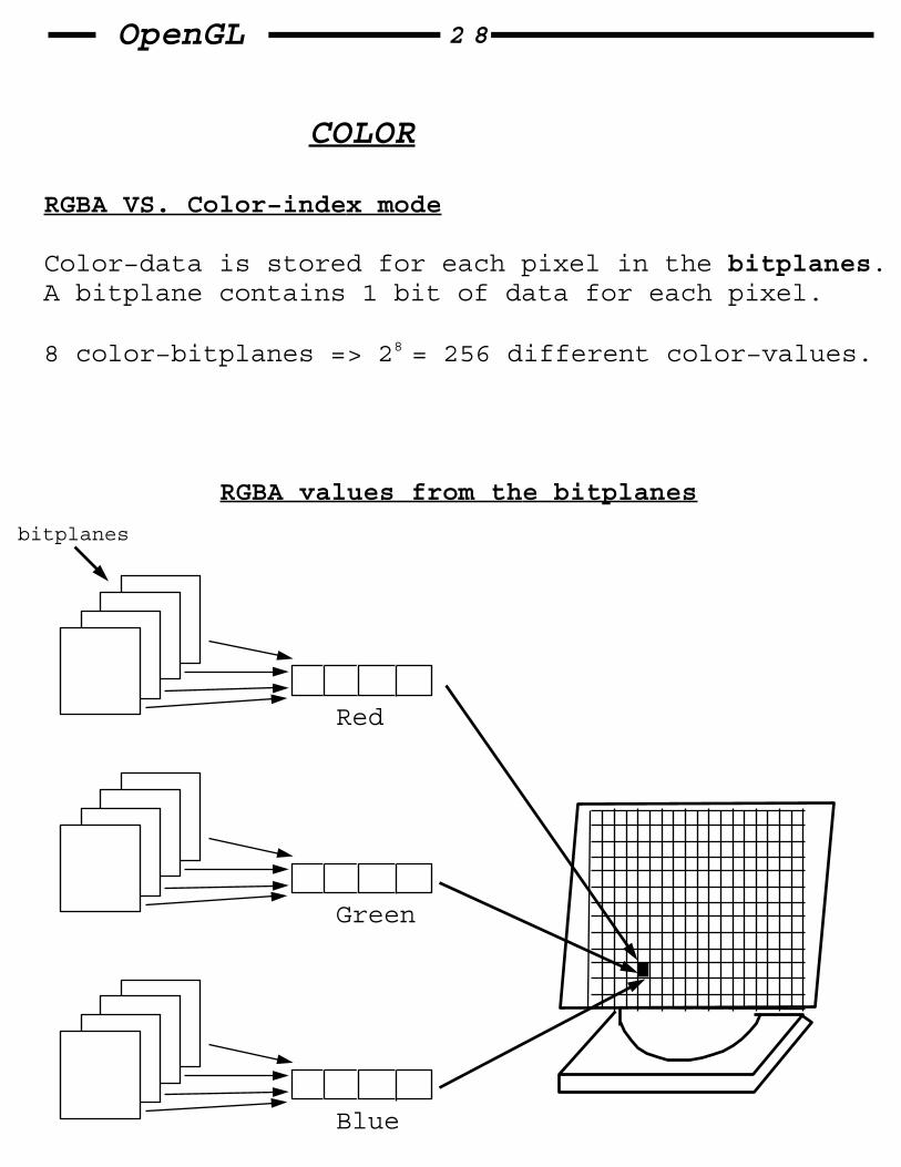
Color−data is stored for each pixel in the bitplanes. A bitplane contains 1 bit of data for each pixel.
8 color−bitplanes => 28 = 256 different color−values.
Red
Green
Blue
RGBA values from the bitplanes
bitplanes

OpenGL 2 9
A color−map
Red Green Blue
0
1
32
296
In OpenGL: glutInitDisplayMode(GLUT_RGB); // for RGB−mode glutInitDisplayMode(GLUT_INDEX); // for color−map
Usually we use RGB mode. It has more colors, andperforms better with several effects (fog, lighting)

OpenGL 3 0
Some more drawing stuff..
void glLineStipple(GLint factor, GLushort pattern); // sets the // current stippling pattern for lines. // factor − how much streching .. // pattern − a 16 bit series of "0" and // "1".
PATTERN FACTOR
0x00ff 1 0x00ff 2 0x0c0f 1 0x0c0f 3 0xAAAA 1 0xAAAA 2
void glPolygonStipple(const GLubyte *mask); // Defines the current stipple−pattern // for filled polygons. // mask − a pointer to 32x32 bitmap.
There are constants to enable/disable these modes.
glEnable/glDisable(GL_LINE_STIPPLE);glEnable/glDisable(GL_POLYGON_STIPPLE);

OpenGL 3 1
Viewing in 3D
void gluLookAt(GLdouble ex, GLdouble ey, GLdouble ez, GLdouble cx, GLdouble cy, GLdouble cz, GLdouble ux, GLdouble uy, GLdouble uz); // Defines a viewing−matrix, and multiplies // it to the right of the current−matrix.
application: 3D interactive−viewing. Trackball, pan, dolly, etc..
x
Y
x
Y
z
z
@@@@
upvector
@@
upvector

OpenGL 3 2
Projection transformation
− Specifyong the projection transformation is like choosing a lens for a camera. It determons the field−of−view or viewing−volume, and therefor what objects are inside it, and (to some extent) how they look.
− In addition, the projection transformation determins how objects are projected onto the screen.
2 projection types:
− perspective (specified by glFrustum) − orthographic (specified by glOrtho)
void glFrustum(GLdouble left, GLdouble right, GLdouble bottom, GLdouble top, GLdouble znear, GLdouble zfar);
frustum
left
bottom right
top
near
far
@@@@@@@@@@@@@@@

OpenGL 3 3
glFrustum isn’t intuitive to use, so we might try the GLU routine:
void gluPerspective(GLdouble fovy, GLdouble aspect, GLdouble near, GLdouble far);
@@@@@@@@@@@@@@@
w
aspect = w/h
near
far
fovy
The default frustum − viewpoint at the origin, and the line−of−sight points down the negative Z−axis.
It’s possible to apply rotations & translations tochange it.

OpenGL 3 4
Orthographic Projection
− Here, the viewing−volume is a box.
toward theviewpoint
bottom
near far
left
top
right
viewing volume
void glOrtho(GLdouble left, GLdouble right, GLdouble bottom, GLdouble top, GLdouble near, GLdouble far); // creates a matrix for an orthographic // parralel viewing volume, and multiplies // the current−matrix by it.

OpenGL 3 5
Aspect ratio & glViewport
− The aspect ratio of a viewport should generally equal the aspect ratio of the viewing−volume. If the two ratios are different, the projected image will be distorted.
@@
@@@@
@@
undistorted distorted
@@@

OpenGL 3 6
Troubleshooting transformations
What should we check when we get the "black screen effect" ?
1) Check the obvious possebilities. Check you’r drawing your objects with a color that’s different from the background color.
2) Remember that "near" & "far" coordinates measure DISTANCE from the viewpoint, and that (by default) you’r looking down the negative Z−axis, thus, if near = 1.0, far = 3.0, objects must have Z coordinates between [−1, −3] to be visible !!
3) Determine where the viewpoint is, in which direction you are looking, and where your objects are (it might help to create a real 3D space..)
4) Make sure you know where you’r rotating about..

OpenGL 3 7
FOV tuning
Even after camera is aimed and the objects are seen, they might appear too small. If gluPerspective is used, a change in the FOV parameter can fix the problem.
− A reasonable fovy can be claculated by trigonometry.
− Typically, you don’t know the exact size/distance of/from an object. To obtain a fairly good approximate value, find the bounding−box for the scene by determining min/max x,y,z coordinates, and calculate the radius of a bounding−sphere for the box. now − use the center of the sphere for the distance, and the radius to determine the size.
@@@@@@@@@@@@@@@
fovy
fovy/2
@@@@@@
distance
size
OpenGL 3 8
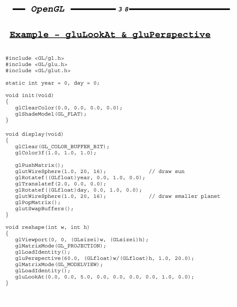
Example − gluLookAt & gluPerspective
#include <GL/gl.h>#include <GL/glu.h>#include <GL/glut.h>
static int year = 0, day = 0;
void init(void){ glClearColor(0.0, 0.0, 0.0, 0.0); glShadeModel(GL_FLAT);}
void display(void){ glClear(GL_COLOR_BUFFER_BIT); glColor3f(1.0, 1.0, 1.0);
glPushMatrix(); glutWireSphere(1.0, 20, 16); // draw sun glRotatef((GLfloat)year, 0.0, 1.0, 0.0); glTranslatef(2.0, 0.0, 0.0); glRotatef((GLfloat)day, 0.0, 1.0, 0.0); glutWireSphere(1.0, 20, 16); // draw smaller planet glPopMatrix(); glutSwapBuffers();}
void reshape(int w, int h){ glViewport(0, 0, (GLsizei)w, (GLsizei)h); glMatrixMode(GL_PROJECTION); glLoadIdentity(); gluPerspective(60.0, (GLfloat)w/(GLfloat)h, 1.0, 20.0); glMatrixMode(GL_MODELVIEW); glLoadIdentity(); gluLookAt(0.0, 0.0, 5.0, 0.0, 0.0, 0.0, 0.0, 1.0, 0.0);}

OpenGL 3 9
void keyboard(unsigned char key, int x, int y){ switch (key) { case ’d’: day = (day + 10) % 360; glutPostRedisplay(); break; case ’D’: day = (day − 10) % 360; glutPostRedisplay(); break; case ’y’: year = (year + 5) % 360; glutPostRedisplay(); break; case ’Y’: year = (year − 5) % 360; glutPostRedisplay(); break; default: break; }}
int main(int argc, char **argv){ glutInit(&argc, argv); glutInitDisplayMode(GLUT_DOUBLE | GLUT_RGB); glutInitWindowSize(500, 500); glutInitWindowPosition(100, 100); glutCreateWindow(argv[0]); init(); glutDisplayFunc(display); glutReshapeFunc(reshape); glutKeyboardFunc(keyboard); glutMainLoop();
return 0;}

OpenGL 4 0
Additional clipping planes
− In addition to the 6 clipping−planes of the viewing−volume (left, right, bottom, top, near,far), you can define up to 6 additional clipping planes.
@@@@@@@@@@@@@@@
void glClipPlane(GLenum plane, const GLdouble *equation // Defines a clipping−plane. "equation" points // to 4 coefficients of the plane−equation // Ax + By + Cz + D = 0. // All points with eye coords (xe, ye, ze, we)
// that satisfy (A B C D)M−1 (xe, ye, ze, we)T >= 0 // lie in the half−space defined by the plane, // where M is the current mdelview−matrix. // "plane" is GL_CLIP_PLANEi .
Note: We need to glEnable(GL_CLIP_PLANEi);
OpenGL 4 1
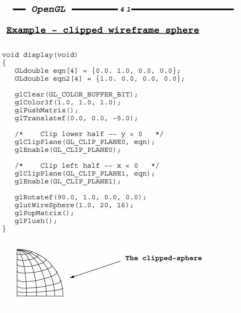
Example − clipped wireframe sphere
void display(void){ GLdouble eqn[4] = {0.0. 1.0, 0.0, 0.0}; GLdouble eqn2[4] = {1.0. 0.0, 0.0, 0.0};
glClear(GL_COLOR_BUFFER_BIT); glColor3f(1.0, 1.0, 1.0); glPushMatrix(); glTranslatef(0.0, 0.0, −5.0);
/* Clip lower half −− y < 0 */ glClipPlane(GL_CLIP_PLANE0, eqn); glEnable(GL_CLIP_PLANE0);
/* Clip left half −− x < 0 */ glClipPlane(GL_CLIP_PLANE1, eqn); glEnable(GL_CLIP_PLANE1);
glRotatef(90.0, 1.0, 0.0, 0.0); glutWireSphere(1.0, 20, 16); glPopMatrix(); glFlush();}
The clipped−sphere

OpenGL 4 2
Reversing transformations
int gluUnProject(GLdouble wx, GLdouble wy, GLdouble wz, const GLdouble modelMatrix[16], const GLdouble projMatrix[16], const GLint viewport[4], GLdouble *x, GLdouble *y, GLdouble *z); // Map the specified window coordinates (wx,wy,wz) // into object coordinates, using transformations // defined by a modelview & projection matrices // and the viewport.
Example:
void mouse(int button, int state, int x, int y){ GLint viewport[4]; GLdouble mvmatrix[16], projmatrix[16]; GLint realy; /* OpenGL y coordinate position */ GLdouble x, y, z; /* returned world x,y,z coordinates */
switch (button) { case GLUT_LEFT_BUTTON: if (state == GLUT_DOWN) { glGetIntegerv(GL_VIEWPORT, viewport); glGetDoublev(GL_MODELVIEW_MATRIX, mvmatrix); glGetDoublev(GL_PROJECTION_MATRIX, projmatrix); realy = viewport[3] − (GLint)y − 1; printf("Coordinates at cursor are (%4d, %4d)\n", x, realy); gluUnProject((GLdouble)x, (GLdouble)realy, 1.0, mvmatrix, projmatrix, viewport, &x, &y, &z); printf("World coords at z=1.0 are (%f, %f, %f)\n", x, y, z); } break;
default: break; }}

OpenGL 4 3
Hidden surface removal
The easiest way (and the way OpenGL is doing it) is to use the depth−buffer (sometimes called Z−buffer).
A depth−buffer works by associating a depth, or distance, from the view−plane to each pixel in the window. Initially, the depth−values for all pixels are set to the largest−possible distance using the glClear command with GL_DEPTH_BUFFER_BIT. Then, the objects in the scene are drawn in any order.
Before each pixel is drawn, a comparasion is done with the depth−value already stored at the pixel. If (new_pixel_closer_than(prev_pixel_Z)) { draw_new_pixel(); store_new_z(pixel_Z); } else { // don’t do anything... }
Example:
glutInitDisplayMode(GLUT_DEPTH | ...); glEnable(GL_DEPTH_TEST); ...
while (1) { glClear(GL_COLOR_BUFFER_BIT | GL_DEPTH_BUFFER_BIT); get_viewing_point_from_mouse_position(); draw_3d_object_A(); draw_3d_object_B();
}
OpenGL 4 4
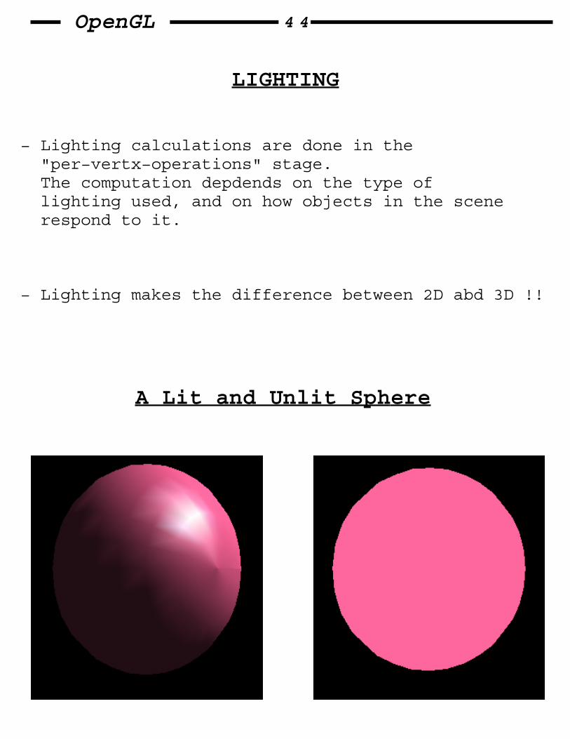
LIGHTING
− Lighting calculations are done in the "per−vertx−operations" stage. The computation depdends on the type of lighting used, and on how objects in the scene respond to it.
− Lighting makes the difference between 2D abd 3D !!
A Lit and Unlit Sphere
OpenGL 4 5
− In OpenGl, light is approximated by RGB components, and the material is characterized by the percentage of the incoming RGB components that is reflected in various directions.
− OpenGL lighting is an approximation !! A more accurate calculations are much more expensive.
− Some light comes from a direction, and some light is generally scattered about the scene.
− Light sources have an effect only when there are surfaces that absorb and reflect light. Each surface is composed of a material.
− OpenGL lighting−model considers the lighting to be divided to 4 independent components:
1) emmisive 2) diffuse 3) ambient 4) specular
All components are computed independently, and then added together.

OpenGL 4 6
NATURE OF THE DIFFERENT COMPONENTS
Ambient illumination: Light that’s been scattered so much by the environment that it’s direction is impossible to determine.
Diffuse component: The light that comes from one direction, so it’s brighter if it comes squarely down on a surface than if it barely glances off the surface. Once it hits the surface, however, it’s scattered equally in all directions.
Specular light: comes from a particular direction, and it tends to bounce of the surface in a preffered direction.
Although a light source delivers a single distribution of prequencies, the ambient, diffuse, and specular components might be different. For example, if you have a white light in a room with red walls, the scattered light tends to be red, although light directly striking objects is white.

OpenGL 4 7
Material Colors
− In OpenGL lighting model, a material’s color depends on the percentage of the incoming RGB light it reflects.
whitelight
GB R
R
RR
R
A RED sphere !!
− Like lights, materials have different ambient, diffuse and specular colors, which determine the ambient, diffuse, and specular reflectances.
− Materials also have an emmisive color, which simulates light originating from an object. In the OpenGL lighting−model, the emmisive color of a surface adds intensity to the object, but is unaffected by any light sources.

OpenGL 4 8
RGB values for lights and materials
Meaning of RGB components in lights: the percentage of full intensity of each color. If the RGB values are (1.0, 1.0, 1.0), light is the brightest possible white. (0.5, 0.5, 0.5) is still color white, but at half intensity, so it appears gray.
Meaning of RGB components in materials: The numbers correspond to the reflected proportions of those colors. So, if RGB=(1, 0.5, 0), that material reflects all the incoming red light, half the incoming green, and none of the incoming blue light.
So − If an OpenGL light has components (LR, LG, LB), and a material has components (MR, MG, MB), then ignoring all other reflectivity effects:
light_to_eye = (LR*MR, LG*MG, LB*MB)
And − If you have 2 lights that send (R1, G1, B1) and (R2, G2, B2) to the eye:
light_to_eye = (R1+R2, G1+G2, B1+B2)
OpenGL 4 9
The steps required to add lighting
1) Define normal vectors for each vertex of all the objects.
2) Create, select, and position one or more light sources.
3) Create and select a lighting−model, which defines the level of global ambient−light and the effective location of the viewpoint (for the purposes of lighting calculations).
4) Define material properties for the objects in the scene.

OpenGL 5 0
Define normal−vectors for each vertex
− A normal−vector is a vector that points perpendicular to a surface. For a curved−surface, the normal direction is different at each point.
void glNormal3{bsidf}(TYPE nx, TYPE ny, TYPE nz); void glNormal3{bsidf}(const TYPE *v); // Sets the current normal vector.
− In OpenGl you can specify a normal for each polygon or for each vertex:
glBegin(GL_POLYGON); glNormal3fv(n0); glVertex3fv(v0); . . glNormal3fv(nn); glVertex3fv(vn); glEnd();
Note: normals indicate direction only. their length is irrelevant, but it has to be "1" before lighting calculations are done.
So − you should supply unit−length normals, and if non−unitar transforms are done, we should normalize again, or do a glEnable(GL_NORMALIZE); in the begining of the program.

OpenGL 5 1
Create and position Light sources
− Your can include at least 8 light sources in your scene (The particular implementation of OpenGL you’r using might allow more than 8).
Note: each light source adds significantly to the rendering caclulations !!
− For each light, you can control it’s color, position, and beam−width (wide or narrow).
− After the definition of light "i", we need to do:
glEnable(GL_LIGHTi);
Also, we need to enable the lighting−feature by:
glEnable(GL_LIGHTING);

OpenGL 5 2
Light−sources in OpenGL
void glLight{if}(GLenum light, GLenum pname, TYPE param); void glLight{if}v(GLenum light, GLenum pname, TYPE *param); // Sets parameters of the light specified by // "light" (GL_LIGHT0, GL_LIGHT1, ...). // "pname" − the parameter name that is set. // param − the value of the parameters.
Default values for the "pname" parameter
Parameter name default−val meaning
GL_AMBIENT (0.0, 0.0, 0.0) ambient RGBA intensity of light
GL_DIFFUSE (1.0,1.0,1.0,1.0) diffuse RGBA intensity of light
GL_SPECULAR (1.0,1.0,1.0,1.0) specular RGBA intensity of light
GL_POSITION (0.0,0.0,1.0,00) (x,y,z,w) light position
GL_SPOT_DIRECTION (0.0, 0.0, −1.0) (x, y, z) spotlight direction
GL_SPOT_CUTOFF 180.0 spotlight spread−angle
GL_{...}_ATTENUATION attenuation−factors..

OpenGL 5 3
Position
− A light source can be located infinitely far away, or one that’s nearer the scene.
directional−light: positioned in infinity. positional−light: positioned near the scene.
GLfloat light_pos1[] = {1.0, 1.0, 1.0, 0.0}; // directional. // light comes from // (1, 1, 1). GLfloat light_pos2[] = {1.0, 1.0, 1.0, 1.0); // positional.
glLightfv(GL_LIGHT0, GL_POSITION, light_pos1); // light "0" is // directional.
glLightfv(GL_LIGHT1, GL_POSITION, light_pos2); // light "1" is // positional.
− The location of a positional−light is transformed by the modelview matrix.
Also, by default, a postional−light radiates in ALL directions, but it’s possible to restrict it to produce a cone of illumination by defining the light as a spotlight.

OpenGL 5 4
Attenuation
− For real lights, the intensity decreases as distance increases. OpenGL attenuates a light source by multiplying the contribution of that source by an attenuation−factor:
attenuation_factor = 1 / (Kc + Kld + Kqd2)
d = distance from light−position to the vertex. Kc = GL_CONSTANT_ATTENUATION Kl = GL_LINEAR_ATTENUATION Kq = GL_QUADRATIC_ATTENUATION
Note: Ambient, diffuse, and specular contributions are all attenuated. Only the emmision and global ambient values aren’t attenuated.
Note: Attenuation requires an additional division for each caclulated−color, so using attenuated lights may slow down application performance.

OpenGL 5 5
Spotlights
− If we specify a GL_SPOT_CUTTOFF value to a postional−light, we get a spotlight.
− By default, the spotlight feature is disabled, because GL_SPOT_CUTTOFF = 180.0
− definition in OpenGL code: glLightf(GL_LIGHT0, GL_SPOT_CUTOFF, 45.0) // cutoff = 45deg GLfloat spot_direction[] = {−1.0, −1.0, 0.0}; glLightfv(GL_LIGHT0, GL_SPOT_POSITION, spot_direction); glLightf(GL_LIGHT0, GL_SPOT_EXPONENT, 2.0);
GL_SPOT_EXPONENT − controls how concentrated the light is. The light’s intensity is highest in the center of the cone. A higher spot−exponent result in a more focused light source.
GL_SPOT_CUTTOFF

OpenGL 5 6
Selecting a lighting model
− The lighting model deals with parameters which are common to all lights−sources (at least of a specific type).
− The OpenGL lighting−model has 3 components:
1) Global ambient light intensity. This is an ambient−light that’s not from any particular source.
2) Local or infinite viewpoint. The intensity of the highlight at a particular "v" depends on the normal at "v", the direction from "v" to the light−source, and the direction from "v" tp the viewpoint.
With an infinite viewpoint, the direction between it and any vertex in the scene remains constant.
3) 2−sided lighting. Whether lighting caclulations should be performed differently for both the front and back faces of objects.

OpenGL 5 7
Light−model in OpenGL
glLightModel{if}( GLenum pname, GLfloat param); glLightModel{if}( GLenum pname, GLfloat *param // sets the properties // of a lighting model. The characteristic of // the lighting model being set is defined by // "pname". "param" indicates values to which // "pname" is set.
Default values for the "pname" parameter
Parameter name default−val meaning
GL_LIGHT_MODEL_AMBIENT (0.2,0.2,0.2) ambient RGBA intensity of the entire scene
GL_LIGHT_MODEL_LOCAL_VIEWER 0.0 or GL_FALSE how specular reflection angles are computed
GL_LIGHT_MODEL_TWO_SIDE 0.0 or GL_FALSE choose between 1−sided or 2−sided lighting

OpenGL 5 8
Example − Rendering a Lit Sphere
void init(void){ GLfloat mat_specular[] = {1.0, 1.0, 1.0, 1.0}; GLfloat mat_shininess[] = {50.0}; GLfloat light_position[] = {1.0, 1.0, 1.0, 0.0}; glClearColor(0.0, 0.0, 0.0, 0.0); glShadeModel(GL_SMOOTH);
glMaterialfv(GL_FRONT, GL_SPECULAR, mat_specular); glMaterialfv(GL_FRONT, GL_SHININESS, mat_shininess); glLightfv(GL_LIGHT0, GL_POSITION, light_position);
glEnable(GL_LIGHTING); glEnable(GL_LIGHT0); glEnable(GL_DEPTH_TEST);}
void display(void){ glClear(GL_COLOR_BUFFER_BIT | GL_DEPTH_BUFFER_BIT); glutSolidSphere(1.0, 20, 16); glFlush();}

OpenGL 5 9
Materials in OpenGL
− Most of the material properties are conceptually similar to the ones we used to create light−sources
glMaterialf( GLenum face, // GL_FRONT, GL_BACK, // or GL_FRONT_AND_BACK GLenum pname, // parameter name GLfloat param);// parameter value
Default values for the "pname" parameter
Parameter name default−val meaning
GL_AMBIENT (0.2,0.2,0.2,1.0) ambient color of a material
GL_DIFFUSE (0.8,0.8,0.8,1.0) diffuse color of a material
GL_AMBIENT_AND_DIFFUSE
GL_SPECULAR (0.0,0.0,0.0,1.0)
GL_SHININESS 0.0 (range: [0−128]) specular exponent
GL_EMISSION (0.0,0.0,0.0,1.0)
GL_COLOR_INDEXES (0, 1, 1)

OpenGL 6 0
Diffuse and ambient Reflection
− The GL_DIFFUSE and GL_AMBIENT parameters affect the color of the diffuse & ambient light reflected by an object.
− Diffuse reflectance plays the most important role in determining what you percieve the color of an object to be.
− For real−world objects, diffuse and ambient reflectance are normally the same color, so OpenGL provides a convinient way of assigning the same value to both simultaneouuuuusly, using GL_AMBIENT_AND_DIFFUSE
SPECULAR Reflection
− The amount of specular reflection seen by a viewer DOES depend on the location of the viewpoint − it’s brightest along the direct angle of reflection.
− The size & brightness of the highlight is controlled by GL_SHININESS. the higher the value is, the smaller and brighter the highlight.
OpenGL 6 1
Changing Material properties
GLfloat no_mat[] = {0.0, 0.0, 0.0, 1.0};GLfloat mat_ambient[] = {0.7, 0.7, 0.7, 1.0};GLfloat mat_ambient_color[] = {0.8, 0.8, 0.2, 1.0};GLfloat mat_diffuse[] = {0.1, 0.5, 0.8, 1.0};GLfloat mat_specular[] = {1.0, 1.0, 1.0, 1.0};GLfloat no_shininess[] = {0.0};GLfloat low_shininess[] = {5.0};GLfloat high_shininess[] = {100.0};GLfloat mat_emission[] = {0.3, 0.2, 0.2, 0.0};
glClear(GL_COLOR_BUFFER_BIT | GL_DEPTH_BUFFER_BIT);
/* draw sphere in first row, first column, * diffuse reflection no ambient or specular. */ glPushMatrix();glTranslatef(−3.75, 3.0, 0.0);glMaterialfv(GL_FRONT, GL_AMBIENT, no_mat);glMaterialfv(GL_FRONT, GL_DIFFUSE, mat_diffuse);glMaterialfv(GL_FRONT, GL_SPECULAR, no_mat);glMaterialfv(GL_FRONT, GL_SHININESS, no_shininess);glMaterialfv(GL_FRONT, GL_EMISSION, no_mat);glutSolidSphere(1.0, 16, 16);glPopMatrix();
/* draw sphere in first row, second column, * diffuse and specular reflection. low shininess. no ambient */ glPushMatrix();glTranslatef(−3.75, 3.0, 0.0);glMaterialfv(GL_FRONT, GL_AMBIENT, no_mat);glMaterialfv(GL_FRONT, GL_DIFFUSE, mat_diffuse);glMaterialfv(GL_FRONT, GL_SPECULAR, no_mat);glMaterialfv(GL_FRONT, GL_SHININESS, no_shininess);glMaterialfv(GL_FRONT, GL_EMISSION, no_mat);glutSolidSphere(1.0, 16, 16);glPopMatrix();

OpenGL 6 2
void glColorMaterial(GLenum face, GLenum mode); // Causes the material property specified // by "mode" of the specified material face // specified by "face" to track the value // of the current color at all times. // A change to the current color (using glColor) // immediateky updates the specified material // properties
− Note: after calling glColorMaterial(), you need to call glEnable(GL_COLOR_MATERIAL)
− Example:
glEnable(GL_COLOR_MATERIAL); glColorMaterial(GL_FRONT, GL_DIFFUSE); /* now glColor* changes diffuse reflection */ glColor3f(0.2, 0.5, 0.8); /* draw some objects here */ glColorMaterial(GL_FRONT, GL_SPECULAR); /* glColor* no longer changes diffuse reflection */ /* now glColor* changes specular reflection */ glColor3f(0.9, 0.0, 0.2); /* draw other objects here */ glDisable(GL_COLOR_MATERIAL);
OpenGL 6 3
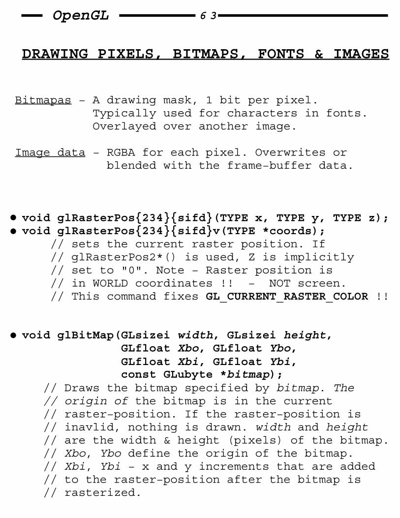
DRAWING PIXELS, BITMAPS, FONTS & IMAGES
Bitmapas − A drawing mask, 1 bit per pixel. Typically used for characters in fonts. Overlayed over another image.
Image data − RGBA for each pixel. Overwrites or blended with the frame−buffer data.
void glRasterPos{234}{sifd}(TYPE x, TYPE y, TYPE z); void glRasterPos{234}{sifd}v(TYPE *coords); // sets the current raster position. If // glRasterPos2*() is used, Z is implicitly // set to "0". Note − Raster position is // in WORLD coordinates !! − NOT screen. // This command fixes GL_CURRENT_RASTER_COLOR !!
void glBitMap(GLsizei width, GLsizei height, GLfloat Xbo, GLfloat Ybo, GLfloat Xbi, GLfloat Ybi, const GLubyte *bitmap); // Draws the bitmap specified by bitmap. The // origin of the bitmap is in the current // raster−position. If the raster−position is // inavlid, nothing is drawn. width and height // are the width & height (pixels) of the bitmap. // Xbo, Ybo define the origin of the bitmap. // Xbi, Ybi − x and y increments that are added // to the raster−position after the bitmap is // rasterized.

OpenGL 6 4
− GLfloat params[4]; glGetFloatv(GL_CURRENT_RASTER_POSITION, ¶ms); // obtain the current raster position.
− GLboolean param; glGetFloatv(GL_CURRENT_RASTER_POSITION_VALID, ¶m); // obtain validity of the current raster // position.
Bitmapped F and it’s data
0xff, 0xc0
0xff, 0xc00xc0, 0x000xc0, 0x00
0xff, 0x00
0xff, 0x00
0xc0, 0x000xc0, 0x00
0xc0, 0x00
0xc0, 0x00
0xc0, 0x000xc0, 0x00

OpenGL 6 5
Example: drawing a bitmapped character
GLubyte rasters[24]= {0xc0, 0x00, 0xc0, 0x00, 0xc0, 0x00, 0xc0, 0x00, 0xc0, 0x00, 0xff, 0x00, 0xff, 0x00, 0xc0, 0x00, 0xc0, 0x00, 0xc0, 0x00, 0xff, 0xc0, 0xff, 0xc0};
void init(void){ glPixelStorei(GL_UNPACK_ALIGNMENT, 1); glClearColor(0.0, 0.0, 0.0, 0.0);}
void display(void){ glClear(GL_COLOR_BUFFER_BIT); glColor3f(1.0, 1.0, 1.0); glRasterPos2i(20, 20); glBitmap(10, 12, 0.0, 0.0, 11.0, 0.0, rasters); glBitmap(10, 12, 0.0, 0.0, 11.0, 0.0, rasters); glBitmap(10, 12, 0.0, 0.0, 11.0, 0.0, rasters); glFlush();}
Bitmappe and it’s Associated Parameters
(Xbo,Ybo)=(0,0)(Xbi,Ybi)=(11,0)
h=12
w=10

OpenGL 6 6
Choosing a color for the bitmap
− glColor*() and glIndex*() are also used to set the GL_CURRENT_RASTER_COLOR and GL_CURRENT_RASTER_INDEX.
The raster−color state variables are set when glRasterPos*() is called, and this can lead to a trap:
glColor3f(1.0, 1.0, 1.0); /* white */ glRasterPos3v(position); glColor3f(1.0, 0.0, 0.0 /* red */ glBitmap(....)
− To get the current raster color or index, we can use
glGetFloatv(GL_CURRENT_RASTER_COLOR, ¶ms); glGetIntegerv(GL_CURRENT_RASTER_INDEX, ¶m);

OpenGL 6 7
Images
Images can come from several sources, such as:
− A photograph that’s digitized with a scanner
− An image that was first generated on the screen by a graphics program, and then read back.
− A program that generated the image in memory
Reading, writing, and copying pixel−data
3 basic commands to manipulate image−data:
glReadPixels(GLint x, GLint y, GLsizei w, GLsizei h, GLenum format, GLenum type, GLvoid *pixels); // Reads pixel data // from the framebuffer rectangle whose lower− // left corner is at (x, y), dimensions are // width and height, and stores it in the array // pointed to by pixels. format indicates the // kind of pixel data elements that are read. // type indicates the data type of each element // (see tables in next page)
Note: You need to clarify which buffer you are trying to access (fornt, back, etc..).
you do that with the glReadBuffer() command.

OpenGL 6 8
format constant Pixel format
GL_COLOR_INDEX A single color index
GL_RGB A red color component, followed by a green color component, followed by blue color component
GL_RGBA like GL_RGB, anf then followed by an alpha color component
GL_RED A single red color component
GL_GREEN A single green color component
GL_BLUE A single blue color component
GL_ALPHA A single red color component
Type constant Data type
GL_UNSIGNED_BYTE unsigned 8−bit integer
GL_BYTE signed 8−bit integer
GL_BITMAP single bits in unsigned 8−bit integers glBitmap’s format.
GL_UNSIGNED_SHORT unsigned 16−bit integer
GL_SHORT signed 16−bit integer
GL_INT signed 32−bit integer
GL_FLOAT single−precision floating point
OpenGL 6 9
glDrawPixels(GLsizei w, GLsizei h, GLenum format, GLenum type, const GLvoid *pixels); // Draws a // rectangle of pixel data with dimensions w, h. // The lower left corner at the current raster // position. format and type have the same // meaning as in glReadPixels(). // pixels is the pixel−data.
glCopyPixels(GLint x, GLint y, GLsizei w, GLsizei h, GLenum buffer); // Copies pixel data // from the framebuffer rectangle whose lower // left corner is (x, y), dimensions are (w, h). // The data is copied to a new position whose // lower left corner is the raster position. // buffer is either GL_COLOR, GL_STENCIL, or // GL_DEPTH, specifying the framebuffer that is // used.
Note: there’s no need for a format or type parameter since the data is never copied into processor memory. The read source and destination buffer are specified by glReadBuffer() and glDrawBuffer() respectively.

OpenGL 7 0
Imaging Pipeline
Processormemory
PixelStorageModes
Pixel−TransferOperations(and Pixel map)
unpack
pack
Rasterization (including Pixel zoom)
Per−FragmentOperations
FrameBuffer
TextureMemory
Pixel Packing and unpacking
Refers to the way data is written to and from the processor memory.
Controlling Pixel−Storage modes
Image data is typically stored in processor memory in rectangular 2D or 3D arrays. Often we want to:
1) store/display a sub−image.
2) adjust to a different byte−ordering conventions.
3) control byte−alignment (2−byte/4−byte/8−byte boundaries in processor memory) since some machines have a hardware that is far more efficient for a specific alignment.

OpenGL 7 1
glPixelStore{if}(GLenum pname TYPE param); // sets the pixel−storage modes. Typically, // several successive calls are made with this // command to set several parameter values. // the GL_UNPACK* parameters control how data is // unpacked from meory by glDrawPixels(), // glBitmap(), glPolygonStipple(), glTexImage1D() // glTexImage2D() etc.. // The GL_PACK* parameters control how data is // packed into memory by glReadPixels() // and glGetTexImage()
Parameter name Type Initial value Valid range
GL_UNPACK_SWAP_BYTES GLboolean FALSE TRUE/FALSEGL_PACK_SWAP_BYTES
GL_UNPACK_LSB_FIRST GLboolean FALSE TRUE/FALSEGL_PACK_LSB_FIRST
GL_UNPACK_ROW_LENGTH GLint 0 anyGL_PACK_ROW_LENGTH nonnegative integer
GL_UNPACK_SKIP_ROWS GLint 0 anyGL_PACK_SKIP_ROWS nonnegative integer
GL_UNPACK_SKIP_PIXELS GLint 0 anyGL_PACK_SKIP_PIXELS nonnegative integer
GL_UNPACK_ALIGNMENT GLint 4 1,2,4,8

OpenGL 7 2
Parameter meaning
SWAP_BYTES: if FALSE, the ordering of the bytes in memory is whatever is native for the OpenGL client.
LSB_FIRST: applies when drawing or reading 1−bit images or bitmaps. If LSB_FIRST is FALSE, the bits are taken from the MSB and on, otherwise − they’re taken in the opposite order. For example, Byte = 0x31 {00110001} // LSB_FIRST == FALSE {10001100} // LSB_FIRST == TRUE
image
SKIP_PIXELS
SKIP_ROWS
ROW_LENGTH
subimage

OpenGL 7 3
Parameter meaning(continued)
ALIGNMENT: Often a particular machine’s hardware is optimized for moving pixel data to and from memory , if the data is saved in memory in a particular byte alignment.
Example: a 32−bit hardware can retrieve data much faster if it’s initially aligned on a 32−bit boundary, which typically has an address that is a multiple of 4.
If ALIGNMENT is set to 1, the next available byte is used. If it’s 2, a byte is skipped if necessary at the end of each row, so that the first byte of the next row has an address that’s a multiple of 2.
QUESTION: If our hardware supports a 4−byte boundary, and we have to show an image which is 5 pixels wide and each pixel has RGB info.
what will be the alignment, and is there a waste in it ?

OpenGL 7 4
Pixel−Transfer Operations
As image data is transferred from memory into the framebuffer, or from the framebuffer into memory, OpenGL can perform operations on it. Examples:
− Ranges of components can be altered.
− Perform arbitrary conversion of color indices or color components.
glPixelTrandfer{if}(GLenum pname, TYPE param); // Sets pixel transfer modes that affect the // operation of glDrawPixels(), glReadPixels() // glTex*()..
Parameter name Type Initial value Valid range
GL_MAP_COLOR GLboolean FALSE TRUE/FALSEGL_MAP_STENCIL GLboolean FALSE TRUE/FALSEGL_INDEX_SHIFT GLint 0 (−inf, inf)GL_INDEX_OFFSET GLint 0 (−inf, inf)GL_RED_SCALE GLfloat 1.0 (−inf, inf)GL_GREEN_SCALE GLfloat 1.0 (−inf, inf)GL_BLUE_SCALE GLfloat 1.0 (−inf, inf)GL_ALPHA_SCALE GLfloat 1.0 (−inf, inf)GL_DEPTH_SCALE GLfloat 1.0 (−inf, inf)GL_RED_BIAS GLfloat 0 (−inf, inf)GL_GREEN_BIAS GLfloat 0 (−inf, inf)GL_BLUE_BIAS GLfloat 0 (−inf, inf)GL_ALPHA_BIAS GLfloat 0 (−inf, inf)GL_DEPTH_BIAS GLfloat 0 (−inf, inf)

OpenGL 7 5
Parameter meaning
MAP_COLOR: if TRUE, then mapping is enabled.
Each of the 4 color−components is multiplied by a scale−factor, and then added to a bias factor.
*SCALE: sets the scale−factors. *BIAS: sets the bias−factors.
Application example: Luminance is compute as the sum of RGB components. If you want to convert RGB to luminance according to the NTSC standard, you set GL_RED_SCALE = 0.3, GL_GREEN_SCALE = 0.59, GL_BLUE_SCALE = 0.11.
INDEX_SHIFT/OFFSET: Indices (color and stencil) can also be transformed, and in this case SHIFT and OFFSET are applied.
Each color index is shifted left by GL_INDEX_SHIFT bits, filling with zeros any bits beyond the number of fraction bits carried by the fixed−point index. If GL_INDEX_SHIFT is negative, the shift is to the right. Then − GL_INDEX_OFFSET is added to the index.

OpenGL 7 6
Pixel−Mapping
All the color components & indices can be modified by means of a table−lookup before they are placed in screen memory.
glPixelMap{ui us f}(GLenum map, GLint mapsize, const TYPE *values); // Loads the pixel map indicated by map with // mapsize entries, whose values are pointed to // by values.
Map name Address value
GL_PIXEL_MAP_I_TO_I color index color index
GL_PIXEL_MAP_S_TO_S stencil index stencil index
GL_PIXEL_MAP_I_TO_R color index R
GL_PIXEL_MAP_I_TO_G color index G
GL_PIXEL_MAP_I_TO_B color index B
GL_PIXEL_MAP_I_TO_A color index A
GL_PIXEL_MAP_R_TO_R R R
GL_PIXEL_MAP_R_TO_R R R
GL_PIXEL_MAP_R_TO_R R R
GL_PIXEL_MAP_R_TO_R R R

OpenGL 7 7
Magnifying/Reducing/Flipping an image
After the pixel storage modes and pixel−transfer operations are applied, images and bitmaps are rasterized. Normally, each pixel in an image is written to a single pixel on the screen. However, you can magnify/reduce/flip an image.
glPixelZoom(GLfloat zoomx, GLfloat zoomy); // Sets the magnification or reduction factors // for pixel−write opertations (glDrawPixels() // or glCopyPixels(). By Default zoomx and zoomy // are 1.0. If they are both 2.0, each image // pixel is drawn to 4 screen pixels. Note that // fractional factors are allowed, as are // negative factors. Negative zoom factors // reflect the resulting image about the current // raster position.
During rasterization, each image pixel is treated as zoomx x zoomy rectangle, and fragments are generated for all the pixels whose centers are lie within the rectangle.

OpenGL 7 8
image−data
currentrasterposition
1 111
zoom = 2
pixels
16 5
2 34987
2 222
Let (Xrp, Yrp) be the current raster−position. If a particular group of elements (index or components is in the n’th row & m’th column, look at the rectangle (in window coordinates) (Xrp+zoomx*n, Yrp+zoomy*m), (Xrp+zoomx*(n+1), Yrp+zoomy*(m+1)
Any framents whose centers lie inside this rectangle (or on its bottom or left boundaries) are produced in correspondence with this group of elements.
A negative zoom can be useful for flipping an image.
How do we correct a video−frame that describes an image "top to bottom" ?

OpenGL 7 9
Example: Drawing, copying, and zooming pixel data.
A checkboard is initially drawn in the lower−left corner. Pressing a mouse and moving it uses glCopyPixels() to copy the lower left corner to the current cursor location. The copied image is zoomed (initially by 1.0). The ’z’ and ’Z’ keys increase/decrease the zoom. pressing ’r’ resets the image and the zoom factors.
#define checkImageWidth 64#define checkImageHeight 64
GLubyte checkImage[checkImageHeight][checkImageWidth][3];
static GLdouble zoomFactor = 1.0;static GLint height;
void MakeCheckImage(void){ int i, j, c;
for (i = 0; i < checkImageHeight; i++) { for (j = 0; j < checkImageWidth; j++) { c = ((((i&0x8)==0)^((j&0x8))==0))*255; checkImage[i][j][0] = (GLubyte)c; checkImage[i][j][0] = (GLubyte)c; checkImage[i][j][0] = (GLubyte)c; } }}
void init(void){ glClearColor(0.0, 0.0, 0.0, 0.0); glShadeModel(GL_FLAT); makeCheckImage(); glPixelStorei(GL_UNPACK_ALIGNMENT), 1);}
OpenGL 8 0
void display(void){ glClear(GL_COLOR_BUFFER_BIT); glRaterPos2i(0, 0); glDrawPixels(checkImageWidth, checkImageHeight, GL_RGB, GL_UNSIGNED_BYTE, checkImage); glFlush();}
void motion(int x, int y){ static GLint screeny;
screeny = height − (GLint)y; glRasterPos2i(x, screeny); glPixelZoom(zoomFactor, zoomFactor); glCopyPixels(0, 0, checkImageWidth, checkImageHeight, GL_COLOR); glPixelZoom(1.0, 1.0); glFlush();}
void keyboard(unsigned char key, int x, int y){ switch (key) { case ’r’: case ’R’: zoomFactor = 1.0; glutPostRedisplay(); break; case ’z’: zoomFactor += 0.5; if (zoomFactor >= 3.0) zoomFactor = 3.0; break; case ’Z’: zoomFactor −= 0.5; if (zoomFactor <= 0.5) zoomFactor = 0.5; break; default: break; }}

OpenGL 8 1
(details of) drawing pixels with glDrawPixels()
byte short in float Data stream(index or component)
unpack
convertto [0,1]
convertL−>RGBA
scalebias
RGBA−>RGBA lookup
ndx−>RGBA lookup
shiftoffset
ndx−>ndx lookup
mask to[0, 2n−1]
clampto [0,1]
PixelStorageModes
PixelTransferModes
RGBA Z
index(stencil, color index)
Pixel Data Out

OpenGL 8 2
(details of) reading pixels with glReadPixels()
pack
Pixels from the Framebuffer
mapto[0,1]
scalebias
RGBA−>RGBA lookup
clampto [0,1]
convertto L
mask to[0, 2n−1]
ndx−>RGBA lookup
ndx−>ndx lookup
shiftoffset
PixelTransferModes
PixelStorageModes
index(stencil, color index)
RGBA Z
byte short int float Data stream(index or component) to memory
OpenGL 8 3
Tips for improving pixel drawing rates
For best performance, set all pixel−transfer parameters to their default values, and set pixel zoom to (1.0, 1.0).
While performing pixel operations, disable other costly states, such as texturing and lighting.
For some implementations, unsigned image formats are faster to use than signed image formats.
It is usually faster to draw a large pixel rectangle than to draw several small ones.
If possible, reduce the amount of data that needs to be copied by using small data−types.
Pixel−transfer operations, including pixel−mapping and values for scale, bias, offset, and shift other than the defaults, may decrease performance.

OpenGL 8 4
TEXTURE−MAPPING
− Texture mapping allows you to glue am image of a brick wall to a polygon and to draw the entire wall as a single polygon. Texture mapping ensures that all the right things happen as the polygon is transformed and rendered.
− Textures are simply rectangular arrays of data (color, luminance, color & alpha). Individual values in a texture are texels.
A texture−mapping example

OpenGL 8 5
Choices when using texture−mapping
− You can repeat a texture in one or both directions to cover a surface.
− A texture can be applied to a surface in different ways:
1) It can be painted on directly (like a decal).
2) used to modulate the color the surface would have been painted otherwise.
3) used to blend a texture−color with the surface color.

OpenGL 8 6
An Overview and an example
Steps in Texture Mapping
1) Specify the texture.
2) Indicate how the texture is to be.
3) Enable texture mapping.
4) Draw the scene, supplying both texture and geometric coordinates.
Specify the texture:
− A texture is USUALLY 2 dimensional. The data describing it can consist of 1, 2, 3, 4 elements per texel, representing anything from a modulation constant to an (R,G,B,A) quadruple.
− For better performance & visual effect, it’s better to use mipmapping. This prevents:
expensive texture−mappingfrom full−scale image tothe small polygon

OpenGL 8 7
Indicate How the texture isto be applied to each pixel:
− There are 3 options:
1) DECAL − texture is painted on top of the fragment.
2) MODULATE − combine texture with the fragment color. This technique is useful for combining the effects of lighting with texturing.
3) BLEND − a constant color is blended with that of the fragment, based on the texture value.
Enable Texture Mapping
− by glEnable or glDisable(GL_TEXTURE_2D/GL_TEXTURE_1D)
Draw the scene, Supplying both texture and geometric coords
− You need to specify BOTH texture & geometric coordinates as you specify the object in your scene.
(1,0)(0,0)
(1,1)(0,1)

OpenGL 8 8
Textures example
full texturetexture−mapped polygon

OpenGL 8 9
Texture−mapping in OpenGL
glTexImage2D(GLenum target, GLint level, GLint components, GLsizei width, GLsizei height, GLint border, GLenum format, GLenum type, const GLvoid *pixels); // Defines a 2D texture. // target: GL_TEXTURE_2D, // GL_DETAIL_TEXTURE_2D_SGIS // level: Specifies the level−of−detail number. // "0" is the base image. "n" is the // n’th mipmap reduction image. // components: an integer, 1 to 4, indicating // which of the RGBA components are // selected for use in modulating and // blending. // width, height: the dimensions of the texture // format, type: the same meaning as they do // for glDrawPixels() // pixels: contains the texture image data.
glTexParameter{if}(GLenum target, GLenum pname, GLfloat param); // Set texture parameters. // target: GL_TEXTURE_2D, // GL_DETAIL_TEXTURE_2D_SGIS // pname: parameter symbolyc−constant. // param: the value of pname.

OpenGL 9 0
glTexCoord2f(GLfloat s, GLfloat t); glTexCoord2fv(const GLfloat *v); // Set the current texture coordinates.
glTexEnvf(GLenum target, GLenum pname, GLfloat param); // set // texture environment parameters. target must be // GL_TEXTURE_ENV. If pname is GL_TEXTURE_ENV_MODE // param can be GL_DECAL, GL_REPLACE, GL_MODULATE, // or GL_BLEND, to specify how texture values are // combined with the fragment color. If pname is // GL_TEXTURE_ENV_COLOR, param is an array of 4 // float values, RGBA, used ONLY with GL_BLEND.
Parameter Values
GL_TEXTURE_WRAP_S GL_CLAMP, GL_REPEAT
GL_TEXTURE_WRAP_T GL_CLAMP, GL_REPEAT
GL_TEXTURE_MAG_FILTER GL_NEAREST, GL_LINEAR
GL_TEXTURE_MIN_FILTER GL_NEAREST, GL_LINEAR, GL_NEAREST_MIPMAP_NEAREST GL_NEAREST_MIPMAP_LINEAR GL_LINEAR_MIPMAP_NEAREST GL_LINEAR_MIPMAP_LINEAR
GL_TEXTURE_BORDER_COLOR any 4 values in [0.0, 1.0]
GL_TEXTURE_PRIORITY [0.0, 1.0] for the current texture object
Params & values for glTexParameterf

OpenGL 9 1
Base internal format Replace tex func Modulate tex func
GL_ALPHA C = Cf, C = Cf, A = At A = AfAt
GL_LUMINANCE C = Lt, C = CfLt, A = Af A = Af
GL_LUMINANCE_ALPHA C = Lt, C = CfLt, A = At A = AfAt GL_INTENSITY C = It, C = CfIt, A = It A = AfIt
GL_RGB C = Ct, C = CfCt A = Af A = Af
GL_RGBA C = Ct, C = CfCt A = At A = AfAt
Base internal format Decal tex func Blend tex func
GL_ALPHA undefined C = Cf, A = AfAt
GL_LUMINANCE undefined C = Cf(1−Lt) + CcLt, A = Af
GL_LUMINANCE_ALPHA undefined C = Cf(1−Lt) + CcLt, A = AfAt GL_INTENSITY undefined C = Cf(1−It) + CcIt A = Af(1−It) + AcIt
GL_RGB C = Ct, C = Cf(1−Ct) + CcCt, A = Af A = Af
GL_RGBA C = Cf(1−At) + CtAt C = Cf(1−Ct) + CcCt, A = Af A = AfAt
These 2 tables show how texturing−function & base internalformat determine the texturibg application formula

OpenGL 9 2
A Sample program
static GLuint texName;
void myinit(void){ glClearColor(0.0, 0.0, 0.0, 0.0); glEnable(GL_DEPTH_TEST); glDepthFunc(GL_LEQUAL);
makeCheckImage(); glPixelStorei(GL_UNPACK_ALIGNMENT, 1); glGenTextures(1, &texName); glTexImage2D(GL_TEXTURE_2D, 0, 3, checkImageWidth, checkImageHeight, 0, GL_RGB, GL_UNSIGNED_BYTE, &checkImage[0][0][0]); glTexParameterf(GL_TEXTURE_2D, GL_TEXTURE_WRAP_S, GL_CLAMP); glTexParameterf(GL_TEXTURE_2D, GL_TEXTURE_WRAP_T, GL_CLAMP); glTexParameterf(GL_TEXTURE_2D, GL_TEXTURE_MAG_FILTER, GL_NEAREST); glTexParameterf(GL_TEXTURE_2D, GL_TEXTURE_MIN_FILTER, GL_NEAREST); glTexEnvf(GL_TEXTURE_ENV, GL_TEXTURE_ENV_MODE, GL_DECAL); glEnable(GL_TEXTURE_2D); glShadeModel(GL_FLAT);}
void display(void){ glClear(GL_COLOR_BUFFER_BIT | GL_DEPTH_BUFFER_BIT); glEnable(GL_TEXTURE_2D); glTexEnvf(GL_TEXTURE_ENV, GL_TEXTURE_ENV_MODE, GL_DECAL); glBindTexture(GL_TEXTURE_2D, texName); glBegin(GL_QUADS); glTexCoord2f(0.0, 0.0); glVertex3f(−2.0, −1.0, 0.0); glTexCoord2f(0.0, 1.0); glVertex3f(−2.0, 1.0, 0.0); glTexCoord2f(1.0, 1.0); glVertex3f(0.0, 1.0, 0.0); glTexCoord2f(1.0, 0.0); glVertex3f(0.0, −1.0, 0.0);
glTexCoord2f(0.0, 0.0); glVertex3f(1.0, −1.0, 0.0); glTexCoord2f(0.0, 1.0); glVertex3f(1.0, 1.0, 0.0); glTexCoord2f(1.0, 1.0); glVertex3f(2.41421, 1.0, −1.41421); glTexCoord2f(1.0, 0.0); glVertex3f(2.41421, −1.0, −1.41421); glEnd(); glFlush();}
Texture mapped squares

OpenGL 9 3
Note − The internal format of a texture image may affect the performance & memory−consumption of the texture operations.
The number of texels for both width & height of atexture image, not including the optional border,MUST be a power of 2. If your original image does nothave such dimensions, you can use the OpenGL utilitylibrary gluScaleImage().
int gluScaleImage(GLenum format, GLint widthin, GLint heightin, GLenum typein, const void *datain, GLint widthout, GLint heightout, GLenum typeout, void *dataout); // Scales an image // using the appropriate pixel storage modes to // unpack the data from datain. The format, // typein, typeout parameters can refer to any // of the formats or data types supported by // glDrawPixels(). The image is scaled using // linear interpolation, and the resulting // image is written to dataout, using the // pixel GL_PACK* storage modes. The caller // of this function must allocate sufficient // space for the output buffer. A value "0" is // returned on success, and a GLU error code is // returned on failure.

OpenGL 9 4
The framebuffer itself can also be used as a sourcefor texture data.
void glCopyTexImage2D(GLenum target, GLint level, GLint internalFormat, GLint x, GLint y, GLsizei width, GLsizei height, GLint border); // Creats a 2D // texture, using framebuffer data to define // the texels. The pixels are read from the // current GL_READ_BUFFER and are processed // exactly as if glCopyPixels() had been called // out but stopped before final conversion. The // settings of glPixelTransfer*() are applied. // target − GL_TEXTURE_2D. level,intern−format, // border, have the same effects like in // glTexImage2D(). The texture array is taken // from a screen−aligned pixel rectangle with // the lower left−corner at (x, y). width & // height are the size of the rectangle.
When using textures, size IS important,because textureresources are typically limited, and vary among OpenGLimplementations.
glGetIntegerv(GL_MAX_TEXTURE_SIZE, ..) // tells you // the largest dimension of a texture image.

OpenGL 9 5
Texture Proxy
A special place holder, or proxy, for a texture image allows the program to query more accurately whether OpenGL can accomodate a texture of a desired internal format. To use the proxy, call glTexImage2D() with target GL_PROXY_TEXTURE_2D and the given level, internalFormat, width, height, border, format & type.
To find out whether there are enough resources available for your texture, after the texture proxy has been created, use the function:
void glGetTexLevelParameter{if}v(GLenum target, GLint level, GLenum pname, TYPE *params); // Returns in params texture parameter values for // a specific level of detail, specified as level. // target defines the target texture. // pname is the paramter we are querying about.
Example: finding out if there are enough resources to create a 64x64 texel texture with RGBA components with 8 bits of resolution. If this succeeds, then the internal format is stored in format.
GLint format;
glTexImage2D(GL_PROXY_TEXTURE_2D, 0, GL_RGBA8, 64, 64, 0, GL_RGBA, GL_UNSIGNED_BYTE, NULL); glGetTexLevelParameteriv(GL_PROXY_TEXTURE_2D, 0, GL_TEXTURE_INTERNAL_FORMAT, &format);

OpenGL 9 6
Replacing all or part of a texture image
− Creating a texture may be more expensive than modifying an existing one. So, there are routines to replace all or part of a texture image with new information.
void glTexSubImage2D(GLenum target, GLint level, GLint xoffset, GLint yoffset, GLsizei width, GLsizei height, GLenum format GLenum type, const GLvoid *pixels); // Defines a 2D texture image that replaces all // or part of a contiguous subregion (rectangle..) // of the current, existing 2D texture image. // target parameter must be set to GL_TEXTURE_2D. // level, format, type parameters are like in // glTextImage2D(). The subimage is affected by // modes of glPixelStore*() & glPixelTransfer*(). // pixels contains the texture−data. width, height // are the dimensions of the replacing subregion. // xoffset and yoffset specify the texel offset in // x, y (0, 0) at the lower left corner of // the texture) and specify where to put the // subimage within the existing texture array. // this region may not include texels outside the // range of the originally defined texure array.
void glCopyTexSubImage2D(GLenum target, GLint level, GLint xoffset, GLint yoffset, GLint x, GLint y, GLsizei width, GLsizei height); // Use image−data from the framebuffer to replace // all/part of a sub−rectangle of the curr texture

OpenGL 9 7
A Sample program
#define checkImageWidth 64#define checkImageHeight 64#define subImageWidth 16#define subImageHeight 16
static GLubyte checkImage[checkImageWidth][checkImageHeight][4];static GLubyte subImage[subImageWidth][subImageHeight][4];
void makeCheckImages(void){ ... ... // fill the checkImage & subImage arrays with image−data.}
void keyboard(unsigned char key, int x, int y){ switch (key) { case ’s’: case ’S’: glBindTexture(GL_TEXTURE_2D, texName); glTexSubImage2D(GL_TEXTURE_2D, 0, 12, 44, subImageWidth, subImageHeight, GL_RGBA, GL_UNSIGNED_BYTE, subImage); glutPostRedisplay(); break;
case ’r’: case ’R’: glBindTexture(GL_TEXTURE_2D, texName); glTexImage2D(GL_TEXTURE_2D, 0, GL_RGBA, checkImageWidth, checkImageHeight, 0, GL_RGBA, GL_UNSIGNED_BYTE, checkImage); glutPostRedisplay(); break;
default: break;}
Texture with subimage added

OpenGL 9 8
One−Dimensional Textures
− Sometimes a 1D texture is sufficient. A 1D texture behaves like a 2D texture with height = 1, and without borders. All the 2D texture & sub−texture routines have a corresponding 1D routines.
Multiple Levels of Detail
Textured objects can (like any other object) be viewed at different distances from the viewpoint. As a textured object moves farther from the viewpoint, the texture map must decrease in size. To do that, OpenGl has to filter the texture−map down. With the plain filtering − we get disturbing visual artifacts.
To avoid such artifacts, OpenGL use MIPMAPS, a series of prefiltered texture maps of decreasing resolutions
When using mipmapping, OpenGL automatically determines which texture map to use based on the size (in pixels) of the object being mapped.

OpenGL 9 9
Original Texture
Pre−Filtered Images
1/4
1/16
1/641 pixel
....
Mipmaps
To use mipmapping, you must provide all sizes of your texture in powers of 2 between the largest size and a 1x1 map.
To specify these textures, call glTexImage2D() once for each resolution of the texture map, with different values for the level, width, height, and image parameters.
An (easyer) alternative:
int gluBuild2DMipMaps(GLenum target, GLint comps, GLint width, GLint height, GLenum format, GLenum type, void *data); // constructs // a series of mipmaps and calls glTexImage*D() // to load the images. The target, components, // width, height, format, type and data are // exactly the same as those of glTexImage*D().

OpenGL 100
Filtering
− Usually, texel −−> pixel matching is NOT one−to−one. In order to apply the texels on the pixels, we need to do some kind of FILTERING.
− If many texles correspond to 1, pixel minification filters are used, and if 1 texel corresponds to many pixels − magnification fileter is used.
− It’s unclear exactly which texlel values should be used and how should they be averaged/interpolated. Consequently, OpenGL allows you to specify any of several filtering options to determin these calculations. The options orovide different trade−offs between speed and image−quality.
Also − you can specify independently the filtering methods for magnification and minification.
Texture TexturePolygon Polygon
Magnification Minification
texel
pixel
potion ofa texel

OpenGL 101
MAG/MIN Filtering Methods
GL_NEAREST − The texel with coordinates nearest the center of the pixel is used. This might result in aliasing artifacts.
GL_LINEAR − A weighted linear average of the 2x2 array of texels that lie nearest to the center of the pixel is used.
GL_NEAREST_MIPMAP_NEAREST − In the nearest mipmap, choose the nearest texel value.
GL_LINEAR_MIPMAP_NEAREST − In the nearest mipmap, interpolate linearly between the 2 nearest texels.
GL_LINEAR_MIPMAP_LINEAR − Interpolate between the nearest values in the 2 best choices from the mipmaps.

OpenGL 102
Texture Objects
A texture object stores texture−data and makes it readily available. Using texture objects is usually the fastest way to apply textures, because it is faster to bind (reuse) an existing texture object than it is to reload a texture image using glTexImage*D().
working set − some OpenGL implementations support a limited working set of high−performance textures.
To use texture objects, the steps are:
1) Generate texture names.
2) initialy bind (create) texture objects to texture data, including the image arrays and texture properties.
3) check if you can use working−set. If there isn’t enough space, you may wish to establish priorities for each texture.
4) Bind and rebind texture objects, making their data currently available for rendering textured models.

OpenGL 103
int glGenTextures(GLsizei n, GLuint *textureNames); // Returns n currently unused names for texture // objects in the array textureNames.
GLboolean glIsTexture(GLuint textureName); // Return GL_TRUE if textureName is the name of // a texture that has been bound and has not been // subsequently deleted. Returns GL_FALSE if // textureName is zero or textureName is a // nonzero value that is not the name of an // existing texture.
void glBindTexture(GLenum target, GLuint textureName); // does 3 things. When using non−zero textureName // for the first−time, a new texture object is // created and assigned that name. When binding // to a previously created zero textureName, // OpenGL stops using texture objects, and // returns to the unnsmed default texture. // // When a texture object is initially bound, it // assumes the dimensinality of target. // Immediately on this initial binding, the // initial state properties (mag/min filters, // wrapping nodes, border color, texture priority // are set.
void glDeleteTextures(GLsizei n, const GLuint *textureNames); // Deletes n texture objects, named by elements in // the array textureNames.

OpenGL 104
Computing Appropriate Texture Coordinates
(0,1) (1,1)
(0,0) (1,0)
No problem(similar shape)
(0,0) (1,0)
(0,0.66) (1,0.66)
need tochange thetex−coords,to preventdistortion
How will we generate texture−coordinates for acomplex 3D object ??
There must be a distortion of the image, but weusually try to make it minimal.
OpenGL 105
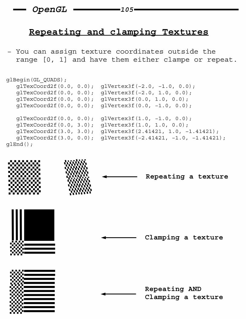
Repeating and clamping Textures
− You can assign texture coordinates outside the range [0, 1] and have them either clampe or repeat.
glBegin(GL_QUADS); glTexCoord2f(0.0, 0.0); glVertex3f(−2.0, −1.0, 0.0); glTexCoord2f(0.0, 0.0); glVertex3f(−2.0, 1.0, 0.0); glTexCoord2f(0.0, 0.0); glVertex3f(0.0, 1.0, 0.0); glTexCoord2f(0.0, 0.0); glVertex3f(0.0, −1.0, 0.0);
glTexCoord2f(0.0, 0.0); glVertex3f(1.0, −1.0, 0.0); glTexCoord2f(0.0, 3.0); glVertex3f(1.0, 1.0, 0.0); glTexCoord2f(3.0, 3.0); glVertex3f(2.41421, 1.0, −1.41421); glTexCoord2f(3.0, 0.0); glVertex3f(−2.41421, −1.0, −1.41421); glEnd();
Repeating a texture
Clamping a texture
Repeating ANDClamping a texture

OpenGL 106
Automatic Texture−Coordinate Generation
− You can use texture mapping to make contours on your models or to simulate the reflections from an arbitrary environment on a shiny model.
To achieve these effects, let OpenGL automatically generate the texture coordinates for you.
void glTexGenf{ifd}v(GLenum coord, GLenum pname, TYPE *param); // Specifies the functions for automatically // generating texture coordinates. // coord − GL_S, GL_T, GL_R, or GL_Q. // pname − GL_TEXTURE_GEN_MODE, GL_OBJECT_PLANE // or GL_EYE_PLANE // param − a pointer to an array of texture // generation params. if pname is // GL_TEXTURE_GEN_MODE, then the array // must contain one of GL_OBJECT_LINEAR, // GL_EYE_LINEAR or GL_SPHERE_MAP. // Otherwise params has the coefficients // for the texture−generation function.
Using GL_OBJECT_LINEAR is best when a texture image remains fixed to a moving object, like putting a wood grain on a table top. GL_EYE_LINEAR is best for producing dynamic contour lines on moving objects.
The texture−generation formulas:
g = P1Xo + P2Yo + P3Zo + P4Wo (GL_OBJECT_LINEAR) g = P’1Xe + P’2Ye + P’3Ze + P’4We (GL_EYE_LINEAR)

OpenGL 107
Creating Contours
When GL_TEXTURE_GEN_MODE and GL_OBJECT_LINEAR are specified, and P2 = P3 = P3 = 0 and P1 = 1, then the texgen function gives the distance between the vertex and the plane X=0.
If our texture is a stripe: , then the mapping will create a contour (lines on equal−distance places).
Since only 1 property is shown, we use 1D texture.
static GLuint texName; static GLfloat xequalzero[] = {1.0, 0.0, 0.0, 0.0}; static GLfloat slanted[] = {1.0, 1.0, 1.0, 0.0}; static GLfloat *currentCoeff; static GLenum currentPlane; static GLint currentGenMode;
void init(void) { glClearColor(0.0, 0.0, 0.0, 0.0); glEnable(GL_DEPTH_TEST); glShadeModel(GL_SMOOTH);
makeStripeImage(); glPixelStorei(GL_UNPACK_ALIGNMENT, 1);
glGenTextures(1, &texName); glBindTextures(GL_TEXTURE1D, texName); glTexParameteri(GL_TEXTURE_1D, GL_TEXTURE_WRAP_S, GL_REPEAT); glTexParameteri(GL_TEXTURE_1D, GL_MAG_FILTER, GL_LINEAR); glTexParameteri(GL_TEXTURE_1D, GL_MIN_FILTER, GL_LINEAR); glTexImage1D(GL_TEXTURE_1D, 0, GL_RGBA, stripeImageWidth, 0, GL_RGBA, GL_UNSIGNED_BYTE, stripeImage); glTexEnvf(GL_TEXTURE_ENV, GL_TEXTURE_ENV_MODE, GL_MODULATE); currentCoeff = xequalzero; currentPlane = GL_OBJECT_PLANE; glTexGeni(GL_S, GL_TEXTURE_GEN_MODE, currentGenMode); glTexGenfv(GL_S, currentPlane, currentCoeff);

OpenGL 108
glEnable(GL_TEXTUREGEN_S); glEnable(GL_TEXTURE_1D); glEnable(GL_CULL_FACE); glEnable(GL_LIGHTING); glEnable(GL_LIGHT0); glEnable(GL_AUTO_NORMAL); glEnable(GL_NORMALIZE); glFrontFace(GL_CW); glCullFace(GL_BACK) glMaterial(GL_FRONT, GL_SHININESS, 64.0); }
void display(void) { glClear(GL_COLOR_BUFFER_BIT | GL_DEPTH_BUFFER_BIT);
glPushMatrix(); glRotatef(45.0, 0.0, 0.0, 1.0); glBindTexture(GL_TEXTURE_1D, texName); glutSolidTeapot(2.0); glPopMatrix(); glFlush(); }
void keyboard(unsigned char key, int x, int y) { switch (key) { case ’e’: currentGenMode = GL_EYE_LINEAR; currentPlane = GL_EYE_PLANE; glTexGeni(GL_S, GL_TEXTURE_GEN_MODE, currentGenMode); glTexGenfv(GL_S, currentPlane, currentCoeff); glutPostRedisplay(); break; case ’o’: currentGenMode = GL_OBJECT_LINEAR; currentPlane = GL_OBJECT_PLANE; glTexGeni(GL_S,GL_TEXTURE_GEN_MODE, currentGenMode); glTexGenfv(GL_S, currentPlane, currentCoeff); glutPostRedisplay(); break; case ’s’: currentCoeff = slanted; glTexEnvfv(GL_S, currentPlane, currentCoeff); glutPostRedisplay(); break; case ’x’: currentCoeff = xequaltozero; glTexEnvfv(GL_S, currentPlane, currentCoeff); glutPostRedisplay(); break; } }

OpenGL 109
Environment Mapping
The goal is to render an object as if it were perfectly reflective.
The objects whose reflections you see depend on the position of your eye and on the position and surface angles of the reflective object.
To find the color of a point on the surface, take a ray from the eye to the surface, and reflect the ray off the surface. The direction of the reflected ray completely determins the color to be painted there.
To make a good environment texture map, you need to obtain a large silvered sphere, take a photo of it in some environment with a far−away camera.
Once you’v created the texture, you activate OpenGL’s algorithm that finds the point on the surface of the sphere with the same tangent−surface as the obj point:
glTexGeni(GL_S, GL_TEXTURE_GEN_MODE, GL_SPHERE_MAP); glTexGeni(GL_T, GL_TEXTURE_GEN_MODE, GL_SPHERE_MAP); glEnable(GL_TEXTURE_GEN_S); glEnable(GL_TEXTURE_GEN_T);
obj
each directionhas a color
eye

OpenGL 110
Blending
− Alpha blending is used to combine the color−value of the fragment being processed with that of the pixel already stored in the framebuffer. Blending occures after your scene has been rasterized and converted to fragments, but just before the final pixels are drawn in the framebuffer.
− Blending is used to create transparency, digital composing & more.
− Blending operations aren’t performed in color−index mode.
− The most natural way to think of blending operations is to think of the alpha component as representing opacity.
blending
Pixel inframebuffer
Fragmentcolor
NewPixel color

OpenGL 111
− Blending combines the incoming fragment (source) with the currently−stored pixel (destination).
Let the blending factors be: (Sr, Sg, Sb, Sa) (Dr, Dg, Db, Da)
and the RGBA values be: (Rs, Gs, Bs, As) (Rd, Gd, Bd, Ad)
then the final, blended RGBA values are given by:
(RsSr+RdDr, GsSg+GdDg, BsSb+BdDb, AsSa+AdDa)
void glBlendFunc(GLenum sfactor, GLenum dfactor); // Controls how color values in the fragment // being processed (the source) are combined with // those already stored in the framebuffer // (the destination). sfactor indicates how to // compute a source blending factor. dfactor // indicates how to compute a destination blending // factor. The blend factors are assumed to lie in // the range [0, 1]. after the color values are // combined, they are clamped to [0, 1].
Note: To have blending take effect, you need to enable it:
glEnable(GL_BLEND);
use glDisbale(GL_BLEND) to disbale blending.

OpenGL 112
The parameters of glBlendFunc
Constant Relevant factor Computed blend fact
GL_ZERO sourse or (0,0,0,0) destination
GL_ONE source or (1,1,1,1) destination GL_DST_COLOR source (Rd,Gd,Bd,Ad)
GL_SRC_COLOR destination (Rs,Gs,Bs,As)
GL_ONE_MINUS_DST_COLOR source (1,1,1,1)−(Rd,Gd,Bd,Ad)
GL_ONE_MINUS_SRC_COLOR destination (1,1,1,1)−(Rs,Gs,Bs,As)
GL_SRC_ALPHA source or (As,As,As,As) destination
GL_ONE_MINUS_SRC_ALPHA source or (1,1,1,1)−(As,As,As,As) destination
GL_DST_ALPHA source or (Ad,Ad,Ad,Ad) destination
GL_ONE_MINUS_DST_ALPHA source or (1,1,1,1)−(Ad,Ad,Ad,Ad) destination
GL_SRC_ALPHA_SATURATE source (f,f,f,1;f=min(As,1−Ad)

OpenGL 113
Sample Uses of Blending
− glBlendFunc(GL_ONE, GL_ZERO); draw_1st_image(); glBlendFunc(GL_SRC_ALPHA, GL_ONE_MINUS_SRC_ALPHA); draw_2nd_image(); // make alpha = 0.5 !!
effect: A picture composed of half one one image and half of another.
− glBlendFunc(GL_SRC_ALPHA, GL_ONE); alpha = 0.3333; draw_3_images();
effect: A picture that blends 3 images equally.
− Suppose you are writing a paint program, and you want to have a brush that gradually adds color so that each brush stroke blends in a little more color with whatever is currently in the image (say 10% more color with 90% image on each pass). To do this, draw the image of the brush with alpha 0.1 and use
glBlendFunc(GL_SRC_ALPHA, GL_ONE_MINUS_SRC_ALPHA);
Note that you can vary the alphas across the brush to make the brush add more of it’s color in the middle and less on the edges.

OpenGL 114
A Blending example (drawing overlappingstatic int leftFirst = GL_TRUE; triangles)/*Initialize alpha blending function */static void init(void){ glEnable(GL_BLEND); glBlendFunc(GL_SRC_ALPHA, GL_ONE_MINUS_SRC_ALPHA); glShadeModel(GL_FLAT); glClearColor(0.0, 0.0, 0.0, 0.0);}
static void drawLeftTriangle(void){/* draw yellow triangle on LHS of screen */ glBegin(GL_TRIANGLES); glColor4f(1.0, 1.0, 0.0, 0.75); glVertex3f(0.1, 0.9, 0.0); glVertex3f(0.1, 0.1, 0.0); glVertex3f(0.7, 0.5, 0.0); glEnd();}
static void drawRightTriangle(void){/* draw cyan triangle on RHS of screen */ glBegin(GL_TRIANGLES); glColor4f(0.0, 1.0, 1.0, 0.75); glVertex3f(0.9, 0.9, 0.0); glVertex3f(0.3, 0.5, 0.0); glVertex3f(0.9, 0.1, 0.0); glEnd();}
void display(void){ glClear(GL_COLOR_BUFFER_BIT);
if (leftFirst) { drawLeftTriangle(); drawRightTriangle(); } else { drawRightTriangle(); drawLeftTriangle(); }}
OpenGL 115
3D Blending with the depth buffer
The order in which polygons are drawn greatly affects the blended result. When drawing 3D transparent objects, you get different appearances depending on the drawing−order (back−to−front or front−to−back).
When depth−buffer is used, obscured portions of surfaces aren’t necessarily drawn and therefore aren’t used for blending.
If you render both opaque and transparent objects in the same scene, you want the depth−buffer to perform hidden−surface removal for any objects that lie behind opaque objects. BUT − for a transparent objects, (which are closer) you want to blend them with the hidden−objects.
for a static scene, it’s possible to find a drawing order that will draw correctly, but the problem can quickly become too hard if either the viewpoint or the object is moving.
The solution is to enable depth−buffering but make the depth−buffer read−only while drawing the transparent objects. First you draw all the opaque objects, with the depth−buffer in normal operation. Then you preserve these depth−values by making the depth−buffer read−only. When the transparent objects are drawn, their depth−values are still compared to the opaque objects, so they aren’t drawn if they are behind the opaque ones. If they are close however, they don’t eliminate the opaque objects − they blend with them. to control depth−buffer write−mode, use glDepthMask();

OpenGL 116
A 3D Blending (and depth buffer) example
#define MAXZ 8.0#define MINZ −8.0#define ZINC 0.4
static float solidZ = MAXZ; static float transparentZ = MINZ;static GLuint sphereList, cubeList;
/*Initialize alpha blending function */static void init(void){ GLfloat mat_specular[] = {1.0, 1.0, 1.0, 0.15}; GLfloat mat_shininess[] = {100.0}; GLfloat position[] = {0.5, 0.5, 1.0, 0.0};
glMaterialfv(GL_FRONT, GL_SPECULAR, mat_specular); glMaterialfv(GL_FRONT, GL_SHININESS, mat_shininess); glLightfv(GL_LIGHT0, GL_POSITION, position); glEnable(GL_LIGHTING); glEnable(GL_LIGHT0); glEnable(GL_DEPTH_TEST);
sphereList = glGenList(1); glNewList(cubeList, GL_COMPILE); glutSolidCube(0.6); glEndList();} void display(void){ GLfloat mat_solid[] = {0.75, 0.75, 0.0, 1.0}; GLfloat mat_zero[] = {0.0, 0.0, 0.0, 1.0}; GLfloat mat_transparent[] = {0.0, 0.8, 0.8, 0.6}; GLfloat mat_emmision[] = {0.0, 0.3, 0.3, 0.6};
glClear(GL_COLOR_BUFFER_BIT | GL_DEPTH_BUFFER_BIT);
glPushMatrix(); glTranslatef(−0.15, −0.15, solidZ); glMaterialfv(GL_FRONT, GL_EMMISION, mat_zero); glMaterialfv(GL_FRONT, GL_DIFFUSE, mat_solid); glCallList(sphereList); glPopMatrix();

OpenGL 117
glPushMatrix(); glTranslatef(0.15, 0.15, transparentZ); glRotatef(15.0, 1.0, 1.0, 0.0); glRotatef(30.0, 0.0, 1.0, 0.0); glMaterialfv(GL_FRONT, GL_EMMISION, mat_emmision); glMaterialfv(GL_FRONT, GL_DIFFUSE, mat_transparent); glEnable(GL_BLEND); glDepthMask(GL_FALSE); glBlendFunc(GL_SRC_ALPHA, GL_ONE); glCallList(cubeList); glDepthMask(GL_TRUE); glDisable(GL_BLEND); glPopMatrix();
glutSwapBuffers();}
void animate(void){ if (solidZ <= MINZ || transparentZ >= MAXZ) glutIdleFunc(NULL); else { solidZ −= ZINC; transparentZ += ZINC; glutPostRedisplay(); }}
void keyboard(unsigned char key, int x, int y){ switch (key) { case ’a’: case ’A’: solidZ = MAXZ; transparentZ = MINZ; glutIdleFunc(animate); break;
case ’r’: case ’R’: solidZ = MAXZ; transparentZ = MINZ; glutPostRedisplay(); break; }}

OpenGL 118
Antialiasing
To perform anti−aliasing, OpenGL calculates a coverage value for each fragment, based on the fraction of the pixel square on the screen that it would cover.
In RGBA mode: alpha = alpha*coverage; blend_line_clr_with_existing_pixel_clr();
In color−index mode: The least significant 4 bits of the color index are set by the coverage (1111: complete coverage)
It’s up to you to load your color map and apply it appropriately to take advantage of this coverage information.
A
B C D E
F G H I
J K L M
NA .040510B .040510C .878469D .434259E .007639F .141435G .759952H .759952I .141435J .007639K .434258L .878469M .040510N .040510
} Coverage values

OpenGL 119
Antialiasing Points or Lines
To antialias points or lines, you need to turn on antialiasing with:
glEnable(GL_POINT_SMOOTH or GL_LINE_SMOOTH);
You might also want to provide a quality hint with glHint().
void glHint(GLenum target, GLenum hint); // Controls certain aspects of OpenGL behaviour. The target // parameter indicates which behaviour is controlled. It’s // possible values are shown later. The hint parameter can be
// GL_FASTEST to indicate that the most efficient // option should be chosen, GL_NICEST to indicate the highest // quality option, or GL_DONT_CARE to indicate no preference. // // The GL_PERSPECTIVE_CORRECTION_HINT target parameter refers // to how color values and texture coords are interpolated // across a primitive: either lineraly on the screen space, // or in a perspective−correct manner
Parameter Meaning
GL_POINT_SMOOTH_HINT Specify the desired samplingGL_LINE_SMOOTH_HINT quality of points,lines,polysGL_POLYGON_SMOOTH_HINT during antialiasing ops.
GL_FOG_HINT Specifies whether fog calculations are done per pixel (GL_NICEST) OR PER VERTEX (GL_FATSEST); GL_PERSPECTIVE_CORRECTION_HINT Quality of interpolation

OpenGL 120
The Framebuffer
− After the rasterization stage (including texturing), The data are not yet pixels, but are fragments. Each fragment has coordinate data which correspond to a pixel, as well as color and depth values. Then, each fragment undergoes a series of tests and operations. If test & operations are survived, the fragment values are ready to become pixels.
− Whenever data is stored uniformly for each pixel, such a storage is called a buffer. A buffer that stores a single bit of information about pixels is called a bitplane.
− The color buffer is only one of several buffers that hold information about a pixel. We have also the depth buffer, stencil buffer, and more. The framebuffer on a system comprises all of these buffers.
− Besides the color−buffer, You don’t view the other buffers directly, but use them to perform some tasks.

OpenGL 121
The Stencil buffer
− One use for the stecil buffer is to restrict drawing to certain portions of the screen.
For example, if you want to draw an image as it would appear through an odd−shaped windshield, you can store an image of the windshield shape in the stencil buffer, and then draw the entire scene. The stencil buffer prevents anything that wouldn’t be visible through the windshield from being drawn.
Stencil Test: takes place only if there is a stencil buffer. It compares a reference value with the value stored at a pixel in the stencil buffer. You can choose the particular comparasion function used, the reference value, and the modification performed, with:
void glStencilFunc(GLenum func, GLint ref, GLuint mask); // sets the comparasion−function, reference−value, and a mask // for use with the stencil test. Comparaion applies only to // those bits where the mask are 1. func can be GL_NEVER, // GL_ALWAYS, GL_LESS, GL_LEQUAL, GL_EQUAL, GL_GEQUAL, GL_GREATER // or GL_NOTEQUAL. If it’s GL_LESS, for example, then the // fragment passes if ref is less than the value in the stencil // buffer.
void glStencilOp(GLenum fail, GLenum zfail, GLenum zpass); // Specifies how the data in the stencil buffer is modified when // a fragment passes or fails the stencil test. The 3 functions // fail, zfail, and zpass can be GL_KEEP, GL_ZERO, GL_REPLACE, // GL_INCR, GL_DECR, or GL_INVERT.

OpenGL 122

OpenGL 123
OpenGL 124

OpenGL 125