open vertical merchandisers · gsvm medium temperature remote and self contained open vertical...
TRANSCRIPT

®
GSVM Medium Temperature
Remote and Self Contained Open Vertical Merchandisers
Installation & Service Manual
P/N 0515275_BDecember 2010
P/N0515275_B
IMPORTANT
Keep in store fo
r future re
ference!


P/N 0515275_B iii
IMPORTANTKEEP IN STORE FOR FUTURE REFERENCE
Quality that sets industry standards!
12999 St. Charles Rock Road • Bridgeton, MO 63044-2483
U.S. & Canada 1-800-922-1919 • Mexico 1-800-522-1900
www.hussmann.com© 2010 Hussmann Corporation
®
Merchandiser must operate for 24 hours before loading product!
Regularly check merchandiser temperatures.
Do not break the cold chain. Keep products in cooler before loading into merchandiser.
These merchandisers are designed
for pre-chilled products only.


ANSI DEFINITIONS . . . . . . . . . . . . . . . . . vi
INSTALLATION
Certification . . . . . . . . . . . . . . . . . . . . . . . . 1-1Hussmann Product Control . . . . . . . . . . . 1-1Shipping Damage . . . . . . . . . . . . . . . . . . . 1-1Location . . . . . . . . . . . . . . . . . . . . . . . . . . . 1-1Self Contained Location . . . . . . . . . . . . . . 1-2Model Description . . . . . . . . . . . . . . . . . . 1-3Unloading . . . . . . . . . . . . . . . . . . . . . . . . . 1-3Exterior Loading . . . . . . . . . . . . . . . . . . . . 1-3Shipping Skid . . . . . . . . . . . . . . . . . . . . . . 1-4Merchandiser Leveling . . . . . . . . . . . . . . . 1-4Optional Legs . . . . . . . . . . . . . . . . . . . . . . 1-4Serial Plate Location . . . . . . . . . . . . . . . . . 1-4Refrigeration Unit Access . . . . . . . . . . . . . 1-4Sealing Merchandiser to Floor . . . . . . . . . 1-4
ELECTRICAL / REFRIGERATION
Merchandiser Electrical Data . . . . . . . . . . 2-1Field Wiring . . . . . . . . . . . . . . . . . . . . . . . 2-1Power Switch . . . . . . . . . . . . . . . . . . . . . . . 2-1Electrical Connections . . . . . . . . . . . . . . . 2-1Electrical Outlet . . . . . . . . . . . . . . . . . . . . 2-1Refrigeration (Self Contained) . . . . . . . . . 2-2Refrigeration (Remote) . . . . . . . . . . . . . . . 2-2Line Sizing (Remote) . . . . . . . . . . . . . . . . . 2-2Waste Outlet and Water Seal . . . . . . . . . . 2-2Electromechanical Controls . . . . . . . . . . . .2-3Defrost Time Clock . . . . . . . . . . . . . . . . . . 2-3Setting Defrost Times . . . . . . . . . . . . . . . . 2-3Temperature Control . . . . . . . . . . . . . . . . . 2-4
START UP / OPERATION
Start-Up . . . . . . . . . . . . . . . . . . . . . . . . . . . 3-1Controls and Adjustments . . . . . . . . . . . . 3-2Load Limits . . . . . . . . . . . . . . . . . . . . . . . . 3-3Stocking . . . . . . . . . . . . . . . . . . . . . . . . . . . 3-3Solar Thermometer . . . . . . . . . . . . . . . . . . 3-3Shelf Weight Limits . . . . . . . . . . . . . . . . . . 3-4
MAINTENANCE
Care and Cleaning . . . . . . . . . . . . . . . . . . . 4-1Do NOT Use: . . . . . . . . . . . . . . . . . . . . . . 4-1Do: . . . . . . . . . . . . . . . . . . . . . . . . . . . . . . . 4-1Removing Scratches from Bumper . . . . . . 4-2Cleaning Discharge Honeycomb . . . . . . . 4-2Cleaning Under Display Pan . . . . . . . . . . 4-2Cleaning Stainless Steel Surfaces . . . . . . . 4-3Cleaning Solar Thermometer . . . . . . . . . . 4-3Cleaning Evaporator Pan . . . . . . . . . . . . . 4-4
SERVICE
Replacing Fan Motors and Blades . . . . . . 5-1Replacing Fluorescent Lamps . . . . . . . . . 5-2Repairing Aluminum Coil . . . . . . . . . . . . . 5-2Troubleshooting Guide . . . . . . . . . . . . . . . 5-3GSVM Accessories . . . . . . . . . . . . . . . . . . 5-4
APPENDIX
Part Numbers . . . . . . . . . . . . . . . . . . . . . . A-1Plan View . . . . . . . . . . . . . . . . . . . . . . . . . A-2Cross Sections and Refrigeration Data . . A-3Electrical Data . . . . . . . . . . . . . . . . . . . . . A-4Shipping Weights and Amps . . . . . . . . . . A-5Wiring Diagrams . . . . . . . . . . . . . . . . . . . A-6
WARRANTY
TABLE OF CONTENTS v
HUSSMANN CORPORATION • BRIDGETON, MO 63044-2483 U.S.A. GSVM Open Vertical Merchandisers

REVISION HISTORY
REVISION B — DECEMBER
1. Added option condensate pan for GSVM
4072 and 5272; Page, 2-2
2. Replaced Bulb illustration; Page 5-2
3. Updated wiring diagram; Page A-11
ORIGINAL ISSUE — NOVEMBER 2010
vi
* * * * * * * * * * * * * * * * * * * * * * * * * *
ANSI Z535.5 DEFINITIONS
• DANGER – Indicate[s] a hazardoussituation which, if not avoided, willresult in death or serious injury.
• WARNING – Indicate[s] a hazardoussituation which, if not avoided, couldresult in death or serious injury.
• CAUTION – Indicate[s] a hazardoussituation which, if not avoided, couldresult in minor or moderate injury.
• NOTICE – Not related to personal injury –Indicates[s] situations, which if not avoided,could result in damage to equipment.
�
�
�
P/N 0515275_B

P/N 0515275_B 1-1
HUSSMANN CORPORATION • BRIDGETON, MO 63044-2483 U.S.A. GSVM Open Vertical Merchandisers
CERTIFICATION
These merchandisers are manufactured to meetANSI / National Sanitation Foundation(NSF®) Standard #7 requirements. Properinstallation is required to maintain certification.Near the serial plate, each case carries a labelidentifying the type of application for whichthe case was certified.
ANSI/NSF-7 Type I - Display Refrigerator / Freezer
Intended for 75°F / 55% RH Ambient Application
ANSI/NSF-7 Type II - Display Refrigerator / Freezer
Intended for 80°F / 55% RH Ambient Application
ANSI/NSF-7 - Display Refrigerator
Intended for Bulk Produce
HUSSMANN PRODUCT CONTROL
The serial number and shipping date of allequipment is recorded in Hussmann’s files forwarranty and replacement part purposes. Allcorrespondence pertaining to warranty orparts ordering must include the serial numberof each piece of equipment involved. This is toensure the customer is provided with the correctparts.
SHIPPING DAMAGE
All equipment should be thoroughly examinedfor shipping damage before and during unloading. This equipment has been carefullyinspected at our factory. Any claim for loss ordamage must be made to the carrier. The car-rier will provide any necessary inspectionreports and/or claim forms.
Apparent Loss or Damage
If there is an obvious loss or damage, it mustbe noted on the freight bill or express receiptand signed by the carrier’s agent; otherwise,carrier may refuse claim.
Concealed Loss or Damage
When loss or damage is not apparent untilafter equipment is uncrated, retain all packingmaterials and submit a written response to thecarrier for inspection within 15 days.
LOCATION
These merchandisers are designed for displaying products in air conditioned storeswhere temperature is maintained at or belowthe ANSI / NSF-7 specified level and relativehumidity is maintained at or below 55%.
Placing refrigerated merchandisers in directsunlight, near hot tables or near other heatsources could impair their efficiency. Likeother merchandisers, these merchandisers aresensitive to air disturbances. Air currents passing around merchandisers will seriouslyimpair their operation. Do NOT allow air conditioning, electric fans, open doors or windows, etc. to create air currents around themerchandiser.
INSTALLATION
Recommended operating ambient temperature is between
65°F (18°C) to 75°F (23.9°C). Maximum relative humidity is 55%.

1-2 INSTALLATION
SELF CONTAINED (LOCATION)
GSVM4060 and GSVM4072 each have frontcondenser air intake and discharge. Maintain aminimum clearance distance of two feet in frontof the merchandiser so that air discharge and airintake is not obstructed.
GSVM-5272 requires a 5 inch minimum clearancebehind the merchandiser and clearance above themerchandiser since its air flows straight throughthe condensing unit compartment. Brackets areprovided for field attachment to obtain this rear 5 inch minimum clearance.
P/N 0515275_B U.S. & Canada 1-800-922-1919 • Mexico 1-800-522-1900 • www.hussmann.com
24 in.
Air Intake
Air Exhaust
Front
Maintain 1 in. Clearance around Sides and Rear
of Merchandiser
Maintain 24 in. Clearance at Front of Merchandiser
Rear
24 in. 5 in.
Air Intake
Air Exhaust
Front
Maintain 1 in. Clearance at Sides
Maintain 24 in. Clearance at Front of Merchandiser
Rear
Maintain 5 in. Clearance at Rear

P/N 0515275_B 1-3
MODEL DESCRIPTION
The GSVM open vertical merchandiser offersversatility in the display of medium temperature(32º F to 41º F) products such as dairy products,prepared salads, pizza and fresh entrees that arepre-chilled in a cooler. Carefully read and followthe instructions prior operating the merchandiser.
UNLOADING
Unloading from Trailer:Lever Bar (also known as a Mule, JohnsonBar, J-bar, Lever Dolly, or Pry Lever)
Move the merchandiser as close as possible toits permanent location and remove all packaging.Check for damage before discarding packaging.Remove all separately packed accessories suchas kits and shelves.
Improper handling may cause damage to themerchandiser when unloading. To avoid damage:
1. Do not drag the merchandiser out of the trailer. Use a Johnson bar (mule).
2. Use a forklift or dolly to remove the merchandiser from the trailer.
EXTERIOR LOADING
Do NOT walk on top of merchandisers or damage to the merchandisers and serious personal injury could occur.
MERCHANDISERS ARE NOT STRUCTURALLY
DESIGNED TO SUPPORT EXTERNAL LOADING suchas the weight of a person. Do not place heavyobjects on the merchandiser.
SHIPPING SKID
Each merchandiser is shipped on a skid to protect the merchandiser’s base, and to make positioning the case easier.
Do not remove the shipping skid until the merchandiser is near its final location. The skidprovides protection for both the merchandiserand the floor.
Remove the skid by raising one end of the merchandiser approximately 6 inches. Block themerchandiser securely, and remove the two skidbolts from the raised end. Replace the bolts with(provided) leg levelers. Repeat this procedure atopposing end. Once the leg levelers are securedin place, the merchandiser may be slid off theskid and placed in its final location.
DO NOT TILT MERCHANDISER ON ITSSIDE OR END WHEN REMOVING SKID.
Once the skid is removed, the merchandisermust be lifted —NOT PUSHED— to reposition.
Check floor where merchandisers are to be setto see if it is a level area. Determine the highestpart of the floor.
HUSSMANN CORPORATION • BRIDGETON, MO 63044-2483 U.S.A. GSVM Open Vertical Merchandisers
CAUTION!Do not walk or put heavy objects on case.
Do NOT remove shipping crate until themerchandiser is positioned
for installation.
WARNING!

1-4 INSTALLATION
MERCHANDISER LEVELING
BE SURE TO POSITION MERCHANDISERS PROPERLY.Level the merchandiser by all four corners.Merchandiser(s) must be installed level toensure proper operation of the refrigerationsystem, and to ensure proper drainage ofdefrost water.
OPTIONAL LEGS
NSF® approved legs replace the leg levelers ifrequired by local health codes. The legs raisethe case 6 inches for cleaning purposes. Anoptional skirt kit can be provided to snap onthe legs.
SERIAL PLATE LOCATION
The serial plate is located on the interior top,left side of the merchandiser. It contains all pertinent information such as model, serial number, amperage rating, refrigerant type andcharge. This information will be needed to install,service or order parts for the merchandiser.
REFRIGERATION UNIT ACCESS
The lower front panel may be removed byremoving screw at bottom and lifting the panelstraight upward and over the tabs on which itis hanging. The panel is installed by reversing theabove procedure.
Ensure lower front panel is flat against thefloor when installed to prevent air circulationproblems for self contained merchandisers.
SEALING MERCHANDISER TO FLOOR
If required by local sanitary codes, or if thecustomer desires, merchandisers may be sealedto the floor using a vinyl cove base trim. Thesize needed will depend on how much variationthere is in the floor, from one end of the merchandiser to the other. Sealing of the lowerfront and rear panels on self contained modelsmay hamper their removal for servicing ormaintenance of the condensing unit.
NOTE: Do not allow trim to cover any intakeor discharge grilles located in the lower frontpanel.
P/N 0515275_B U.S. & Canada 1-800-922-1919 • Mexico 1-800-522-1900 • www.hussmann.com
Serial Plate
Lift up and
out to remove
access panel
FFiirrsstt
TThheenn

P/N 0515275_B 2-1
HUSSMANN CORPORATION • BRIDGETON, MO 63044-2483 U.S.A. GSVM Open Vertical Merchandisers
MERCHANDISER ELECTRICAL DATA
Refer to Appendix A of this manual or themerchandiser’s serial plate for electrical information.
FIELD WIRING
Field wiring must be sized for componentamperes stamped on the serial plate. Actualampere draw may be less than specified.
ELECTRICAL CONNECTIONS
All wiring must be in compliance with NECand local codes. All electrical connections(for remote models, GSVM-4072 and 5072 self-contained) are to be made in the electricalHandy Box located behind the removable basepanel at the left end of the merchandiser whenfacing the discharge air honeycomb.
POWER SWITCH
The main electrical power switch is locatedbehind the front louvered access panel. Thepower switch must be turned OFF before servicing the merchandiser.
ELECTRICAL OUTLET:
Before the merchandiser is connected to anywall circuit, use a voltmeter to check that theoutlet is at 100% of the rated voltage. The wallcircuit must be dedicated for the merchandiser.Failure to do so voids the warranty. Do not usean extension cord. Never plug in more thanone merchandiser per electrical circuit.
• Always use a dedicated circuit with the amperage stated on the unit.
• Plug into an outlet designed for the plug.• Do not overload the circuit• Do not use long or thin extension cords.
Never use adapters.• If in doubt, call an electrician.
GSVM-4060 hasa factory-installedpower cord that isattached at theelectrical box.
ELECTRICAL / REFRIGERATION
ALWAYS CHECK THE SERIAL PLATE FOR
COMPONENT AMPERES
— LOCK OUT / TAG OUT —To avoid serious injury or death from electricalshock, always disconnect the electrical powerat the main disconnect when servicing orreplacing any electrical component. Thisincludes, but is not limited to, such items asdoors, lights, fans, heaters, and thermostats.
WARNING!
Merchandiser must be grounded.
Do not remove the power supply cord ground.
WARNING!
Risk of Electric Shock. If cord or plug
becomes damaged, replace only with
a cord and plug of the same type.
CAUTION!

2-2 INSTALLATION
P/N 0515275_B U.S. & Canada 1-800-922-1919 • Mexico 1-800-522-1900 • www.hussmann.com
REFRIGERATION(Self Contained Models)
Each self contained model is equipped withits own condensing unit and control panellocated beneath the display area. The correcttype of refrigerant will be stamped on eachmerchandiser’s serial plate. The merchandiserrefrigeration piping is leak tested. The unit ischarged with refrigerant, and shipped fromthe factory with all service valves open.
GSVM models have a refrigeration systemthat uses a hermetic compressor. GSVM-4060and GSVM-4072 systems use a capillary tubefor refrigerant control. The capillary tube issoldered to the suction line pull-out coil forproper heat exchange. If the capillary shouldbecome plugged or damaged, it is best to replacethe heat exchanger.
GSVM-5272 employs a bleed port typeexpansion valve for proper refrigerant control. Read the merchandiser’s serial platefor the appropriate refrigerant type andweight.
REFRIGERATION(Remote Models)
Refrigeration temperature is controlled by afactory-installed thermostat. The thermostatcontrols a liquid line solenoid valve (not providedwith the merchandiser). The thermostat energizes the valve as the temperature rises. Apump down system is recommended for outdoor condensing units.
LINE SIZING(Remote Models)
Refrigerant line connections are made at theright end of merchandiser (facing front)beneath the refrigerated display area. Therefrigerant line connection size is 3/8 in. Thesuction line is 5/8 in. Refrigerant lines should besized as shown on the refrigeration legend thatis furnished for the store or according toASHRAE guidelines.
WATER OUTLET AND WATER SEAL
GSVM models 4072 and 5272 require a floordrain. The condensate water outlet is located inthe center of the merchandiser. The outlet hasa factory installed, external water seal.
For self contained models like GSVM-4060,this water seal drains into a high-humidityelectric condensate pan located beneath themerchandiser. The pan uses a thermistor thatsenses water in the pan, adjusting the amountof heat required to evaporate the water. Ensurethe drain hose is properly trapped, and the drainarea is not clogged.
NOTE: An optional high-humidity electriccondensate pan is available for GSVM models4072 and 5272. If this option is ordered, a dedicated 120V circuit must be used with thisoption.
For remote models, the heated condensate panis not provided. Connect the drain hose to afloor drain. Ensure that the drain hose is properly trapped.
NOTE: All lower base panels must be in place whenthe refrigerator is operating. If not, airflow from thecondenser will be directed over the evaporator panand defrost water in the pan may overflow.
Refrigeration lines are under pressure.Refrigerant must be recovered beforeattempting any connection or repair.
WARNING!

P/N 0515275_B 2-3
ELECTROMECHANICAL CONTROLS
These merchandisers require defrost cyclesfor proper operation. Refer to the datasheets for application data. Defrosts aretime-initiated and time terminated. The defrosttimer duration is factory set.
DEFROST TIME CLOCK
To access the defrost time clock remove thefront access panel, and remove the electricalbox cover
The clock has screws that initiate defrostaccording to the time of day. The failsafesetting sets the length of defrost from two minutes to 110 minutes.
When defrost starts, the evaporator fans continue to circulate air across the evaporatorcoil, melting any frost build-up.
To ensure a thorough defrost, it may be neces-sary to increase the failsafe time in high ambi-ent conditions.
The time arrow must be set to the correct time ofday. Turn the knob until the appropriate timeon the wheel lines up with the time arrow.
SETTING DEFROST TIMES
Defrost times are factory set for three defrostsfor GSVM-4060 and GSVM-4072. There arefour factory-set defrost for GSVM-5272.
Additional defrosts may be required formerchandisers located in high humidity or highuse areas. Avoid setting defrost during the day,or peak use periods.
If it is desired to change the factory-set defrostsettings, move the defrost start time screw to correspond to the desired defrost time on thedefrost wheel.
Set the length of time for the defrost (failsafe).Push down on the adjustment and slide it tothe length of time. Do not set the time longerthan 60 minutes.
HUSSMANN CORPORATION • BRIDGETON, MO 63044-2483 U.S.A. GSVM Open Vertical Merchandisers
When brazing pipes, be sure to use theinsulation blanket shipped with the
merchandiser to prevent damage to themetal merchandiser bottom.
CAUTION!
Time Arrow
Defrost Time
Start Screw
Product will be degraded and may spoil if
allowed to sit in a non-refrigerated area.
WARNING!

2-4 INSTALLATION
TEMPERATURE CONTROL
Interior cabinet temperatures are controlledthrough the use of a bulb and capillary typetemperature control. The control is located inthe electrical box.
The sensing bulb is mounted on top of theevaporator coil on the GSVM-4060 andGSVM-4072. The sensing bulb is located onthe rear wall behind the evaporator coil on theGSVM-5272. Be sure to disconnect electricalpower prior to servicing the control.
The temperature control is factory set tobetween 19º F (-7º C) and 21º F (-6º C) for theGSVM-4060, GSVM-4072, and 26º F (-3ºC) to28º F (-2º C) for the GSVM-5272 in order tomaintain between 32º F (0º C) and 40º F (4º C)interior average temperatures.
The differential is set between 8º F (13º C) and10º F (-12º C) or a little over halfway towardsmaximum. Do not adjust lower or evaporatoricing will occur. It can be adjusted to otherdesired temperatures by turning the dial to thecorresponding dial face temperatures. The indicated dial temperature will not directly correspond to the actual cabinet temperaturedue to the bulb location and depending on various conditions. A certain amount of timelag will be noticed between the new setting andthe resulting temperature.
P/N 0515275_B U.S. & Canada 1-800-922-1919 • Mexico 1-800-522-1900 • www.hussmann.com

START UP
Follow the electromechanical controls start upprocedures as detailed in Section 2 of thismanual.
Each self contained merchandiser has its ownevaporator coil. Model GSVM-5272 has anexpansion valve (TEV). The TEV has been factory set at design conditions to provide the recommended performance. GSVM-4060 andGSVM-4072 have capillary tubes.
a. Check the interior cabinet thoroughly for loose nuts, bolts and electrical connections.
b. Inspect the refrigeration lines for visible damage or chafing.
c. Replace electrical box cover and access panel.
d. Turn on the electrical power, power switch and start the merchandiser. The merchandiser must pull down in temperature. Allowmerchandiser 24 hours to operate before loading product.
TEV Adjustment (GSVM-5272 only)
Expansion valves may be adjusted to fully feedthe evaporator. Before attempting to adjustvalves, make sure the evaporator is clear oronly lightly covered with frost, and the merchandiser is within 10°F of its expectedoperating temperature.
Adjust the valve as Follows:
a. Attach a probe to the suction line near theexpansion valve bulb.
b. Obtain a pressure reading from the factoryinstalled Schraeder valve. Convert the pressurereading to a saturated temperature for therefrigerant.
Temperature (b) minus Temperature (a) is thesuperheat. The valve should be adjusted sothat the greatest difference between the twotemperatures is 3° F (-16º C) to 5° F (-15º C).
Make adjustments of no more than 1/2 turn ofthe valve stem at a time and wait for at least 15minutes before rechecking the probe tempera-ture and making further adjustments.
HUSSMANN CORPORATION • BRIDGETON, MO 63044-2483 U.S.A. GSVM Open Vertical Merchandisers
P/N 0515275_B 3-1
START UP / OPERATION
Probe Locations

1. The T-stat controller controls refrigerationtemperature. This is factory installed in thecontrol panel. Adjust this control knob tomaintain the discharge air temperature shown.Measure discharge air temperatures at the center of the discharge honeycomb.
Defrosts are time initiated and time terminatedfor self contained and remote. The defrost setting is factory set as shown above.
3-2 START UP / OPERATION
P/N 0515275_B U.S. & Canada 1-800-922-1919 • Mexico 1-800-522-1900 • www.hussmann.com
CONTROLS and ADJUSTMENTS
Model
GVSM-5272
Product Application
Discharge Air Temperature
Defrost Frequency (per day)
Type of Defrost
Temp. Termination
Failsafe Time (Minutes)
3 Off Time Time 20
Medium Temp. (Dairy, Deli)
3 Off Time Time 20
Medium Temp. (Dairy, Deli)
4 Off Time Time 30
Refrigeration Controls
Defrost Controls
(Remote and Self Contained)
GVSM-4060
GVSM-4072
Medium Temp. (Dairy, Deli)(Remote and
Self Contained)
(Remote and Self Contained)

HUSSMANN CORPORATION • BRIDGETON, MO 63044-2483 U.S.A. GSVM Open Vertical Merchandisers
P/N 0515275_B 3-3
LOAD LIMITS
Each merchandiser has a load limit decal. Shelflife of perishables will be short if load limit is violated.
AT NO TIME SHOULD MERCHANDISERS BE
STOCKED BEYOND THE LOAD LIMITS INDICATED.
DO NOT BLOCK AIR LOUVERS.
STOCKING
Product should NOT be placed inside the merchandisers until merchandisers are at proper operating temperature.
Allow merchandiser 24 hours to operate beforeloading product.
Proper rotation of product during stocking is necessary to prevent product loss. Always bringthe oldest product to the front and set thenewest to the back.
AIR DISCHARGE AND RETURN FLUES MUST
REMAIN OPEN AND FREE OF OBSTRUCTION AT
ALL TIMES to provide proper refrigeration andair curtain performance. Do not allow prod-uct, packages, signs, etc. to block these grilles.Do not use non-approved shelving, baskets,display racks, or any accessory that couldhamper air curtain performance.
Do not allow product to be placed outside ofthe designated load limits in the illustration atleft. Air flows through the back wall, over theproduct on the shelves, across the face of theproduct (air curtain), and into the return airgrille.
SOLAR THERMOMETER
GSVM models have solar thermometers. Thethermometer is located at the top, front centerof the merchandiser’s cabinet interior.
Temperature is displayed in Fahrenheit degreesas a standard option. Celsius is also an avail-able option. The thermometer may be replacedif it becomes damaged.
To replace: remove the two screws securing thethermometer to its mounting bracket. Removethe sensing element from the clip, and installthe new thermometer in reverse order.
Product will be degraded and may spoil if
allowed to sit in a non-refrigerated area.
WARNING!
LOAD LIMIT
Air Flow
Coil
CO
LD A
IR C
UR
TAIN
CORRECT WRONG
Air Flow
Coil
CO
LD A
IR C
UR
TAIN
Do not stock product past shelves

3-4 START UP / OPERATION
SHELF MAXIMUM WEIGHT LIMITS
Hussmann merchandiser shelves are designedto support the maximum weight load limits asindicated in the table below.
Exceeding these maximum weight load limitsmay cause damage to the shelf or shelves,damage to the merchandiser, damage to storeproducts, and potentially create a hazardouscondition for customers and staff. Exceedingthe indicated maximum weight load limits con-stitutes misuse as described in the HussmannLimited Warranty.
GSVM-4060 has two standard shelves forproduct display. The 13 in. shelf should bepositioned above the 15 in. shelf. ModelsGSVM-5272 and GSVM-4072 have an additional standard 13 in. shelf that is also tobe positioned above the 15 in. shelf.
P/N 0515275_B U.S. & Canada 1-800-922-1919 • Mexico 1-800-522-1900 • www.hussmann.com
125 lb (56.7 kg)
200 lb (90.7 kg)
250 lb (113.4 kg)
75 lb (34 kg)
30 lb (13.6 kg)100 lb (35.4 kg)
1
250 lb (113.4 kg) 250 lb (113.4 kg)

P/N 0515275_B 4-1
HUSSMANN CORPORATION • BRIDGETON, MO 63044-2483 U.S.A. GSVM Open Vertical Merchandisers
CARE AND CLEANING
Long life and satisfactory performance of anyequipment is dependent upon the care itreceives. To ensure long life, proper sanitationand minimum maintenance costs, these merchandisers should be thoroughly cleaned,all debris removed and the interiors washeddown, weekly.
Exterior SurfacesThe exterior surfaces must be cleaned with amild detergent and warm water to protect andmaintain their attractive finish. NEVER USE
ABRASIVE CLEANSERS OR SCOURING PADS.
Interior SurfacesThe interior surfaces may be cleaned with mostdomestic detergents, ammonia based cleanersand sanitizing solutions with no harm to thesurface. Self contained models empty into alimited capacity evaporation pan, which willoverflow if excess water is used in cleaning.
Do NOT Use:
•Abrasive cleansers and scouring pads, as thesewill mar the finish.
•Coarse paper towels on coated glass.
•Ammonia-based cleaners on acrylic parts.
•Solvent, oil or acidic based cleaners on any interior surfaces.
•Do not use high pressure water hoses.
Do:
•Disconnect electrical power before cleaning.
•Remove the product and all loose debris toavoid clogging the waste outlet.
•Store product in a refrigerated area such as a cooler. Remove only as much product as canbe taken to the cooler in a timely manner.
•Thoroughly clean all surfaces with soap andhot water. DO NOT USE STEAM OR HIGH WATER
PRESSURE HOSES TO WASH THE INTERIOR. THESE
WILL DESTROY THE MERCHANDISERS’ SEALING
CAUSING LEAKS AND POOR PERFORMANCE.
•Lift hinged fan plenum for cleaning. Hookchain in rear panel to secure plenum duringcleaning. BE SURE TO REPOSITION THE FAN
PLENUM AFTER CLEANING MERCHANDISER.
•Take care to minimize direct contact betweenfan motors and cleaning or rinse water.
•Do NOT flood merchandiser with water.NEVER INTRODUCE WATER FASTER THAN THE
WASTE OUTLET CAN REMOVE IT.
SELF CONTAINED MODELS EMPTY INTO AN
EVAPORATION PAN THAT WILL OVERFLOW IF TOO
MUCH WATER IS INTRODUCED DURING CLEANING.
•Allow merchandisers to dry before resumingoperation.
•After cleaning is completed, turn on power tothe merchandiser.
MAINTENANCE
PPrroodduucctt wwiillll bbee ddeeggrraaddeedd aanndd mmaayy ssppooiill iiff aalllloowweedd ttoo ssiitt iinn aa nnoonn--rreeffrriiggeerraatteedd aarreeaa..
WARNING!
Do NOT allow cleaning agent or
cloth to contact food product.
WARNING!

4-2 MAINTENANCE
CLEANING DISCHARGE HONEYCOMB
Discharge air honeycombs should be cleanedevery six months. Dirty honeycombs willcause merchandisers to perform poorly.The honeycombs may be cleaned with a vacuumcleaner. Soap and water may be used if allwater is removed from the honeycombs cellsbefore replacing. Be careful not to damage thehoneycombs.
1. Using a flat object such as a screw driver, compress the honeycomb and remove it from its retainer.
2. Clean and dry the air honeycombs.
3. After cleaning, replace in reverse order.Damaged honeycombs must be replaced.
CLEANING STAINLESS STEEL SURFACES
Use non-abrasive cleaning materials, andalways polish with grain of the steel. Use warmwater or add a mild detergent to the water andapply with a cloth. Always wipe rails dry afterwetting.
Use alkaline chlorinated or non-chlorine containing cleaners such as window cleanersand mild detergents. Do not use cleaners containing salts as this may cause pitting andrusting of the stainless steel finish. Do not usebleach.
CLEANING SOLAR THERMOMETER
GSVM models have solar thermometers. Thethermometer is located at the top, front centerof the merchandiser’s cabinet interior.
To clean the thermometer:1. Remove the two screws securing the ther-
mometer to its mounting bracket. Removethe sensing element from the clip
2. Use non-abrasive cleaning materials and amild detergent to clean thermometer.
3. Be sure to wipe the element clean of anyresidues.
P/N 0515275_B U.S. & Canada 1-800-922-1919 • Mexico 1-800-522-1900 • www.hussmann.com
Do NOT use HOT water on Cold glass Surfaces.This can cause the glass to shatter and could
result in personal injury. Allow glass fronts, towarm before applying hot water.
WARNING!
— LOCK OUT / TAG OUT —To avoid serious injury or death from electricalshock, always disconnect the electrical powerat the main disconnect when servicing orreplacing any electrical component. Thisincludes, but is not limited to, such items asdoors, lights, fans, heaters, and thermostats.
WARNING!
DO NOT FLOOD!Use only enough water necessary to clean
surface. Water must not drip down the case!
Never use ammonia based cleansers, abrasivecleansers, or scouring pads.
CAUTION!

CLEANING UNDER DISPLAY PAN
Remove all product from the merchandiser andplace in cooler. Always disconnect electricalpower before cleaning.
1. Remove the display pan
2. Use non-abrasive cleaning materials and amild detergent to clean display pan.
3. Wipe down the insides of the merchandiserwith a mild detergent, and replace displaypan. Allow merchandiser to pull down intemperature before loading product.
CLEANING EVAPORATION PAN(GSVM-4060 STANDARD)
(GSVM-4072/5272-OPTIONAL)
The condensate water outlet for selfcontained models empties into a limitedcapacity evaporation pan.
Debris or dirt accumulation inside the condensateevaporation pan or on the heater coil willreduce the pan’s evaporation capacity andcause premature heater failure. The evaporationpan waste water will overflow and spill onto thefloor if the heater is not properly operating.
Remove accumulated debris from the evapora-tion pan. Wipe down heater coil with a clothand warm water. Be sure to remove any dirt,debris or liquids from the heater coil.
Water introduced during cleaning will causethe evaporation pan to overflow.
P/N 0515275_B 4-3
HUSSMANN CORPORATION • BRIDGETON, MO 63044-2483 U.S.A. GSVM Open Vertical Merchandisers
EEvvaappoorraattiioonn PPaann iiss HHoott!!
aanndd ppoosseess rriisskk ooff bbooddiillyy iinnjjuurryy – AAllwwaayyss WWeeaarr gglloovveess
aanndd pprrootteeccttiivvee eeyyee wweeaarr wwhheenn sseerrvviicciinngg.. TTuurrnn ooffff
eevvaappoorraattiioonn ppaann hheeaatteerr,, aanndd aallllooww ppaann ttoo ccooooll..
CAUTION!Fan
Merchandiser with display pan removed

4-4 MAINTENANCE
CLEANING COILS
Condenser coils should be cleaned at least onceper month. Additional cleaning may be neededdepending on the operational environment. Adirty condenser blocks normal airflow throughthe coils.
Airflow blockage increases energy consump-tion and reduces the merchandiser’s ability tomaintain operating temperature.
To clean the coils, use a vacuum cleaner with awand attachment and a soft (non-metallic)brush to remove dirt and debris. Do not bendcoil fins. Always wear gloves and protective eyewear when cleaning near sharp coil fins anddust particles.
REMOVING SCRATCHES FROM BUMPER
Most scratches and dings can be removedusing the following procedure.
1. Use steel wool to smooth out the surfacearea of the bumper.
2. Clean area.
3. Apply vinyl or car wax and polish surfacefor a smooth glossy finish.
P/N 0515275_B U.S. & Canada 1-800-922-1919 • Mexico 1-800-522-1900 • www.hussmann.com
SHUT FANS OFF DURING CLEANING PROCESS.
WARNING!
PRECAUTION CLEANING PRECAUTIONS
When Cleaning:
UNIT WITH AN EVAPORATION PAN
THAT HAS OIL BASE (these will dissolve the butyl sealants) or an AMMONIA BASE (this will corrode the copper components of the merchandiser)
(these will mar the finish)

P/N 0515275_B 5-1
HUSSMANN CORPORATION • BRIDGETON, MO 63044-2483 U.S.A. GSVM Open Vertical Merchandisers
REPLACING FAN MOTORS AND BLADES
Should it ever be necessary to service orreplace the fan motors or blades be certainthat the fan blades are reinstalled correctly.THE BLADES MUST BE INSTALLED WITH RAISED
EMBOSSING (PART NUMBER ON PLASTIC BLADES)POSITIONED AS INDICATED ON THE PARTS LIST.
For access to these fans:1. Remove product and place in a refrigerated
area. Disconnect electrical power.
2. Remove bottom pan.
3. Disconnect fan from wiring harness.
4. If it is determined that fan motor needs tobe replaced, remove fan motor bracketsfrom the fan plenum as shown.
7. Replace fan motor and/or blades.
8. Install brackets to fan motor and motorbracket to the fan plenum.
9. Reconnect fan motor to wiring harness.
10. Turn on power.
11. Verify that motor is working and blade isturning in the correct direction.
12. Reinstall display pans. Bring merchandiserto operating temperature before restocking.
SERVICE
— LOCK OUT / TAG OUT —To avoid serious injury or death from electricalshock, always disconnect the electrical powerat the main disconnect when servicing orreplacing any electrical component. Thisincludes, but is not limited to, such items asdoors, lights, fans, heaters, and thermostats.
WARNING!
Product will be degraded and may spoil if
allowed to sit in a non-refrigerated area.
WARNING!
Fan
Motor
Bracket
Fan
Plenum

5-2 SERVICE
P/N 0515275_B U.S. & Canada 1-800-922-1919 • Mexico 1-800-522-1900 • www.hussmann.com
REPLACING FLUORESCENT LAMPS
Fluorescent lamps have a plastic shield. Whenthe lamp is replaced, keep the lamp shield toinstall over the new lamp.
The switch under the display lamp cover operates both the display lamp and interiorlamps.
Remove Plastic Pins Attaching Display Lamp.
— LOCK OUT / TAG OUT —To avoid serious injury or death from electricalshock, always disconnect the electrical powerat the main disconnect when servicing orreplacing any electrical component. Thisincludes, but is not limited to, such items asdoors, lights, fans, heaters, and thermostats.
WARNING!

P/N 0515275_B 5-3
HUSSMANN CORPORATION • BRIDGETON, MO 63044-2483 U.S.A. GSVM Open Vertical Merchandisers
TROUBLESHOOTING GUIDE
PROBLEM
Compressor will not start.(no noise)
Compressor will not start; cuts out on overload.
Warm storage temperature
Compressor runs continuously;product too warm.
Compressor runs continuously;product too cold
PROBABLE CAUSE
1. Power disconnected
2. Blown fuse or breaker
3. Defective or broken wiring
4. Defective overload
5. Defective temperature control
1. Low voltage
2. Defective compressor
3. Defective relay
4. Restriction (pinched cap tube)
5. Restriction (moisture)
6. Condenser blocked with dust and dirt
7. Defective condenser fan motor
1. Temperature control not set properly
2. Short or refrigerant
3. Cabinet location too warm
4. Refrigerant over-charge
5. Low voltage, compressor cycling on overload
1. Short of refrigerant
2. Inefficient compressor
1. Defective control
2. Control sensing element not in positive contact
3. Short on refrigerant
SOLUTION
1. Check service cord or wiring connection
2. Replace fuse or reset breaker
3. Repair or replace
4. Replace
5. Replace
1. Cabinet voltage must not be more than 5% below rating
2. Replace
3. Replace
4. Repair or replace
5. Leak check, replace drier evacuate and recharge
6. Clean condenser
7. Replace
1. Reset control
2. Leak check, replace drier evacuate and recharge
3. Move to cooler location or correct excessive heat source
4. Purge system, evacuate and recharge
5. Compressor voltage must notbe more than 5% below rating
1. Leak check, replace drier, evacuate and recharge
2. Replace
1. Replace
2. Assure proper contact
3. Leak check, replace drier evacuate and recharge

P/N 0515275_B U.S. & Canada 1-800-922-1919 • Mexico 1-800-522-1900 • www.hussmann.com
TROUBLESHOOTING LIGHT GUIDE
PROBLEM
Lights won’t start
Lights flicker
SOLUTION
1. Check light switch
2. Check continuity to ballast
3. Check to see if bulbs are inserted properly in sockets
4. Check voltage
1. Allow lamps to warm up
2. Check lamp sleeve for cracks
3. Check sockets for moisture and proper contact
4. Bulb replacement may be necessary
5. Check voltage
6. New bulbs tend to flicker until used
5-4 SERVICE
GSVM ACCESSORIES
The following is a description of the variousaccessories available for the GSVM.
Caster Kit — Consists of 5 in. braking casters,which screw in to the standard threaded holesin the four corners under the cage occupied bythe standard leg levelers. The kit will add 5 5/8 in. of height to the case.
Leg Kit — The legs also go into the same holesas the standard levelers, which will have to beremoved. The legs are adjustable and will add 5 5/16 in. to the height of the case. The skirt kitrequires the use of these legs.
Four-sided Skirt Kit — This is a four-sidedskirt that encloses the open area under themerchandiser when the leg kit is used. Theskirt kit clamps to the legs.
Night Cover — This is a clear, 5 mm thick,polyester shade cover that covers the face ofthe merchandiser. It will fasten to the top ofthe merchandiser and be drawn to a snap fastener in the area above the front bumper.The cover, although loose fitting on the ends,will conserve energy during periods when thestore is not open. The cover is standard on theGSVM-5272.
Wrap-Around Bumper Kit — This bumperreplaces the standard front bumper and wrapsaround both sides of the merchandiser at thestandard height of 22 inches to the centerlineof the 2 1/4 in. wide bumper.
Colored Accent Panel — This panel can be (a.)the top front panel over the product, (b.) thepanel behind the bumper, or (c.) the accesspanel below the bumper panel, or any combination of these.

Shelf end Trim Kit — Consists of four paintedsteel ends for the standard 13 in. and 15 in.shelves. This trim conceals and protects theexposed ends of the shelves. The trim kitattaches by two snap fasteners supplied witheach trim piece for the GSVM-4060 model.
High Humidity Condensate Pan — (ForGSVM-4072 & 5272) This is a 1,000 watt, 9Amp. pan with a 6 ft - 9 in. 115V power cordattached. A dedicated circuit is required.
Shelf Upslope Tilt Adapter Kit — This kit con-sists of four zinc coated wire adapters toincrease the two standard shelves, upslopefrom 1 1/2º to 6º.
Price Tag Molding Kit — This kit consists ofaluminum price tag molding for the standardshelves. Price tag moulding will hold both 1 in.and 1.235 in. standard price tags. (Note thatthe standard shelves accept 1.235 in. tags.)
Wire Product Stop Kit — This kit consists of a2 in. high chrome plated open wire stops forthe standard shelf. This stop is mounted undertension and should not be confused with thewire front in the partition kit.
Wire Partition Kit — This is a free-standingwire system, which attaches to the standardshelves, and consists of a wire front, (differentfrom the product stop) two wire sides and twopartitions from the front to back, all chromeplated and 3 inches high.
Wire Cross Divider — This is a 3 inches highand 4 inch-long divider that could be orderedto be used with the wire partition kit above.
Wire Basket Kits — One kit is available toreplace the top 13 in. shelf or shelves, anotheris available to replace the bottom 15 in. shelf.Each kit consists of a wire basket, two brackets,and two dividers, which could also be used asends. These parts are zinc plated. The basketshave an 8 in. high back and a 4 in sloped front.
Wire Basket Dividers — These are additionaldividers, which can be with the wire baskets kitto obtain additional partitioned areas in thebaskets.
Additional Lighted Shelf — This consists of anadditional 13 in. lighted shelf that can be positioned between the two standard shelves. Itis the same construction as the top standard 13 in. shelf.
HUSSMANN CORPORATION • BRIDGETON, MO 63044-2483 U.S.A. GSVM Open Vertical Merchandisers
P/N 0515275_B 5-5


HUSSMANN CORPORATION • BRIDGETON, MO 63044-2483 U.S.A. GSVM Open Vertical Merchandisers
APPENDIX A — TECHNICAL DATA A-1
Item Part # Description
FAN ASSEMBLIES AND THERMOSTATS
GSVM-4060, GSVM-4072, GSVM-5272
5W Standard Fan Assembly MO.4410333 Motor — 120V/60 Hz
FB.21S080 Fan Blade
CT.4480216 Refrigeration Thermostat
EP.19S63612 Cord, Power Supply(GSVM 4060 only)
HEATERS
GSVM-4060 (ONLY)HE.19S678 Condensate Pan Heater
115V, 350W
HE.4969309 Condensate Pan
CONTROL PANEL
SW.4440542 GSVM-4060 - Power Switch
SW.4440546 GSVM-4072 & 5272Power Switch
SW.4481941 Time Clock, 120/60
Item Part # Description
REFRIGERATION
EQ.4671069 Condensing Unit Assembly (GSVM-4060 & 4072)
EQ.4671068 Condensing Unit Assembly (GSVM-5272)
TP.4612640 Cap Tube Assembly(GSVM-4060 & 4072)
VR.4613892 Crankcase Pressure Regulator
VR.4613899 Expansion Valve(GSVM-5272)
FI. 4611347 Drier (GSVM-4060 & 4072)
FI.4612641 Drier (GSVM-5272)
TM.4910245 Solar Thermometer
LAMPS AND BALLASTS
EP.4481936 Ballast (GSVM-4060 & 4072)
EP.4481962 Starter, Lamp, 20W
BA.4480866 Ballast (GSVM-5272)
EP.4480867 Starter, Lamp, 40W
Fluorescent LampReplace with like fixtures.

A-2 APPENDIX A — TECHNICAL DATA
P/N 0515275_B U.S. & Canada 1-800-922-1919 • Mexico 1-800-522-1900 • www.hussmann.com
ELEC. BOX
DR
AIN
PA
N
CO
ND
EN
SIN
G
UN
IT
2 5/8 (67)
ELECTRICAL OUTLET DRAIN
REFRIGERATION OUTLET
2 7/8
(73)
24 7/8
(632)
30 5/8
(778)
3 1/2
(89)
3 1/2
(89)
A
B
3 (76)
3 (76)
3 7/8
(98)
MODEL GSVM 4072 16" 40"GSVM 4060 24" 52"
GSVM
General GSVM-4060 GSVM-5272
Case Length (Note: Includes One Pair Ends) 40 in. (1016) 52 in. (1321)Optional End Bumpers (One Pair) 2 (51) 2 (51)
Waste Outlet LH end of case (from outside of End Assembly) 16 (406) 24 (610)to center of waste outlet

HUSSMANN CORPORATION • BRIDGETON, MO 63044-2483 U.S.A. GSVM Open Vertical Merchandisers
APPENDIX A — TECHNICAL DATA A-3
REFRIGERATION DATA
GSVM-4060 GSVM-4072GSVM-5272
ThermostatSetting CI/CO (°F)
GSVM-4060/4072 20 / 29GSVM-5272 25 / 34
Condensing Unit (hp) 3/4 hp (All Models)
Condensing UnitCapacity
GSVM-4060/4072 4410GSVM-5272 4610(Btu/hr at std. ratingconditions)
DEFROST DATA
Frequency (hr)GSVM-4060/4072 8GSVM-5272 6
OFFTIME
Failsafe (minutes)GSVM-4060/4072 20GSVM-5272 30
Defrost TerminationTime Terminated
PHYSICAL DATA
Refrigerant Charge GSVM-4060 (R134a) 33 oz 0.936 kg GSVM-4072 (R134a) 32 oz 0.907 kgGSVM-5272 (R404a) 46.5 oz 1.318 kg
FAN COIL
30 5/8 (778)
25 (635)
17 3/8 (441)
25 (635)
29 3/8 (746)
72 (1829)
25 1/4 (641)
15 (381)
13 (330)
13 (330)
Dimensions shown as inches and (mm).
Note: This data is based on store temperatureand humidity that does not exceed 75°F and55% R.H. unless otherwise stated. Scheduledefrost at night while lights are off.
FAN COIL
15 (381)
13 (330)
60 (1524)
25 1/4 (641)
25 (635)
30 5/8 (778)
17 3/8 (441)
25 (635)
29 3/8 (746)
GSVM-4060
GSVM-4072GSVM-5272

A-4 APPENDIX A —TECHNICAL DATA
P/N 0515275_B U.S. & Canada 1-800-922-1919 • Mexico 1-800-522-1900 • www.hussmann.com
Electrical Data
Note: These are rated values for individual components and should not be added together to determine total merchandiser electrical load.
GSVM-4060/4072 GSVM-5272
Number of Fans – 4W (open shell) 2 3
Amperes Watts Amperes WattsEvaporator Fans
115V 60Hz Standard 0.8 8 1.2 12
Condensate Pan Heaters (115V) 3 350GSVM-4060 (only)
Condensing Unit (115V, 1Ph, 60Hz) Standard
GSVM-4060/4072Compressor LRA 66.3Compressor RLA 11.8
GSVM-5272Compressor LRA 60.0Compressor RLA 13.2
Product Data
GSVM-4060ARI Total Display Area 1 (Sq Ft/Case) 11.70 ft2 /case ( 1.086 m2 /case)
GSVM-4072ARI Total Display Area 1 (Sq Ft/Case) 16.65 ft2 /case ( 1.546 m2 /case)
GSVM-5272ARI Total Display Area 1 (Sq Ft/Case) 20.22 ft2 /case ( 1.878 m2 /case)
1 Computed using AHRI 1200 standard methodology:Total Display Area, ft2 [m2] / Unit of Length, ft [m]

HUSSMANN CORPORATION • BRIDGETON, MO 63044-2483 U.S.A. GSVM Open Vertical Merchandisers
APPENDIX A — TECHNICAL DATA A-5
Nominal Refrigerant Run Nema Fuse HP Type Volts Amps Plugs Amps Hz/Ph
GSVM-4060 3/4 R134a 115 16 5-20P 20 60/1
GSVM-4060R R134a 115 5.0 Hard Wired* 15 60/1
GSVM-4072 3/4 R134a 115 17.0 Hard Wired* 25 60/1
GSVM-4072R R134a 115 5.0 Hard Wired* 15 60/1
GSVM-5272 3/4 R404a 115 19.5 Hard Wired* 25 60/1
GSVM-5272R R404a 115 5.0 Hard Wired* 15 60/1
* Requires field wiring.
ESTIMATED SHIPPING WEIGHT 2
Case self contained remote End
GSVM-4060 380 lb (172kg) 308 lb (140kg) Included
GSVM-4072 425 lb (193kg) 353 lb (160kg) Included
GSVM-5272 600lb (272kg) 520 lb (236kg) Included
2 Actual weights will vary according to optional kits included.

P/N 0515275_B U.S. & Canada 1-800-922-1919 • Mexico 1-800-522-1900 • www.hussmann.com
A-6 APPENDIX A — WIRING DIAGRAMS
R = Red Y = Yellow G = Green BL = Blue BK = Black W = White
= 120V POWER = 120V NEUTRAL = FIELD GROUND = CASE GROUND
WARNING All components must have mechanical ground, and the merchandiser must be grounded.
CIRCLED NUMBERS = PARTS LIST ITEM NUMBERS
WARNING:
Unplug merchandiser before attempting to make any electrical connections.
LIGHT SWITCH
LAMP
BALLAST
SOPTIONAL SHELF LIGHT
LIGHT SWITCH
LAMP
BALLAST
SSTD. SHELF LIGHT
LAMP
BALLAST
S
LIGHT SWITCH
STD. SHELF LIGHT
S1
BA
LLA
ST
GRD
CONDENSATE PAN
POWER SWITCHS3
115 V 60 Hz 1 Ph
UPPER LIGHT
LAMP
LIGHT SWITCH
STARTER
S 2
N
1
TIME CLOCK
TEMP. CONTROL
COND. FAN
EVAP. FANS
T
1 3 5 7 9 11
23
25
10
12
24
262 4 6 8
3-S
-226
ELE
C-T
RO
N
4 3 X
WIRE HARNESS
PROTECTOR
RR
BK
BL
BK
R
BL
W
W
BK
BKG
R
W
W
BK
BK
BK
BK
G
POWER CORD
W
BK
#1 RELAY
COMPRESSOR
W
BK
W
BK
W
BK
W
GSVM 4060 WIRING DIAGRAM
M100-1938X
C
1 2
ONE LIGHTED SHELF

HUSSMANN CORPORATION • BRIDGETON, MO 63044-2483 U.S.A. GSVM Open Vertical Merchandisers
APPENDIX A — WIRING DIAGRAMS A-7
COMPRESSOR
W
STARTER
S
S1
BA
LLA
ST
1 3 5 7 9 11
23
25
10
12
24
262 4 6 8
3-S
-226
ELE
C-T
RO
N
POWER SWITCHS3115 V
60 Hz 1 Ph
R
BL
BL
W
BKW
GBK
BK
WG
W
BK
W
BK
BK
UPPER LIGHT
LAMP
LIGHT SWITCH
EVAP. FANSRR
BK
BK
WIRE HARNESS
2
N
1
TIME CLOCK
TEMP. CONTROL
T
4 3 X
PROTECTORR BK
#1 RELAY
1 2
GSVM 4072 WIRING DIAGRAM
M100-1935-1
C
COND. FAN
LAMP
BALLAST
S
LAMP
BALLAST
SOPTIONAL SHELF LIGHT
OPTIONAL CONDENSATE PAN (1,000W; 9A; 120V) USE COPPER CONDUCTORS ONLY
FIELD WIRING
LIGHT SWITCH
STD. SHELF LIGHT
LIGHT SWITCHBK
W
BK
W
LAMP
SSTD. SHELF LIGHT
LIGHT SWITCH
LAMP
BALLAST
S
LIGHT SWITCH
BALLAST
BK
W
BK
W
STD. SHELF LIGHT
R = Red Y = Yellow G = Green BL = Blue BK = Black W = White
= 120V POWER = 120V NEUTRAL = FIELD GROUND = CASE GROUND
WARNING All components must have mechanical ground, and the merchandiser must be grounded.
CIRCLED NUMBERS = PARTS LIST ITEM NUMBERS

P/N 0515275_B U.S. & Canada 1-800-922-1919 • Mexico 1-800-522-1900 • www.hussmann.com
A-8 APPENDIX A — WIRING DIAGRAMS
W
STARTER
S
S1
BA
LLA
ST
1 3 5 7 9 11
23
25
10
12
24
262 4 6 8
3-S
-226
ELE
C-T
RO
N
POWER SWITCHS3115 V
60 Hz 1 Ph
R
BL
BL
W
BKW
GBK
BK
WG
W
BK
W
BK
BK
UPPER LIGHT
LAMP
LIGHT SWITCH
EVAP. FANSRR
BK
BK
WIRE HARNESS
2
N
1
TIME CLOCK
TEMP. CONTROL
COND. FANST
4 3 X
PROTECTORR BK
#1 RELAY
COMPRESSOR
C
1 2
GSVM 5272 WIRING DIAGRAM
M100-1872A
OPTIONAL CONDENSATE PAN (1,000W; 9A; 120V) USE COPPER CONDUCTORS ONLY
FIELD WIRING
LIGHT SWITCH
LAMP
BALLAST
SOPTIONAL SHELF LIGHT
LIGHT SWITCH
LAMP
BALLAST
SSTD. SHELF LIGHT
BK
W
W BL
BK
W
W BL
LIGHT SWITCH
LAMP
BALLAST
SSTD. SHELF LIGHT
LIGHT SWITCH
LAMP
BALLAST
SSTD. SHELF LIGHT
BK
W
W BL
BK
W
W BL
R = Red Y = Yellow G = Green BL = Blue BK = Black W = White
= 120V POWER = 120V NEUTRAL = FIELD GROUND = CASE GROUND
WARNING All components must have mechanical ground, and the merchandiser must be grounded.
CIRCLED NUMBERS = PARTS LIST ITEM NUMBERS
HUSSMANN CORPORATION • BRIDGETON, MO 63044-2483 U.S.A. GSVM Open Vertical Merchandisers
LIGHT SWITCH
BALLAST
OPTIONAL SHELF LIGHT
LIGHT SWITCH
BALLAST
STD. SHELF LIGHT
LAMP
BALLAST
S
LIGHT SWITCH
STD. SHELF LIGHT
LAMP
S
LAMP
S
USE COPPER CONDUCTORS ONLY
FIELD WIRING
W
BK
W
BK
W
BK
W
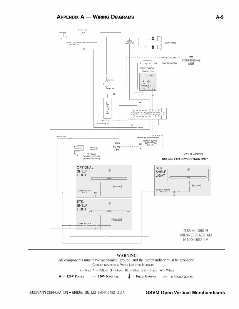
GSVM 4060-R WIRING DIAGRAM
M100-1993-1A
STARTER
S 2
N
1
TIME CLOCK
TEMP. CONTROL
TO CONDENSING
UNIT
EVAP. FANS
S1
BA
LLA
ST
1 3 5 7 9 11
23
25
10
12
24
262 4 6 8
3-S
-226
ELE
C-T
RO
N
4 3 X
POWER SWITCHS3115 V
60 Hz 1 Ph
R
BL
BL
W
BK
WIRE HARNESS
W FIELD CONN.
BK FIELD CONN.BKR
W
BK
W
GBK
BK
WG
BK
OPTIONAL CONDENSATE PAN (1,000W; 9A; 120V)
T
UPPER LIGHT
LAMP
LIGHT SWITCH
RR
BK
BK
R = Red Y = Yellow G = Green BL = Blue BK = Black W = White
= 120V POWER = 120V NEUTRAL = FIELD GROUND = CASE GROUND
WARNING All components must have mechanical ground, and the merchandiser must be grounded.
CIRCLED NUMBERS = PARTS LIST ITEM NUMBERS
APPENDIX A — WIRING DIAGRAMS A-9

P/N 0515275_B U.S. & Canada 1-800-922-1919 • Mexico 1-800-522-1900 • www.hussmann.com
R = Red Y = Yellow G = Green BL = Blue BK = Black W = White
= 120V POWER = 120V NEUTRAL = FIELD GROUND = CASE GROUND
WARNING All components must have mechanical ground, and the merchandiser must be grounded.
CIRCLED NUMBERS = PARTS LIST ITEM NUMBERS
TIME CLOCK
TEMP. CONTROL
TO CONDENSING
UNIT
WIRE HARNESS
W FIELD CONN.
BK FIELD CONN.BKR
STARTER
GSVM 4072-R WIRING DIAGRAM
M100-2008A
RR
BK
BK
R
BL
BL
W
BK
W
BK
W
GBK
BK
WG
BK
W
BK
W
BK
W
BK
WBK
W
X34
ELE
C-T
RO
N
3-S
-226
2 4 6 8 10
12
24
26
9 11
23
251 3 5 7
BA
LLA
ST
T
1
N
2S
LIGHT SWITCH
LAMP
UPPER LIGHT
OPTIONAL SHELF LIGHT
S
BALLAST
LAMP
LIGHT SWITCH
STD. SHELF LIGHT
S
BALLAST
LAMP
LIGHT SWITCH
STD. SHELF LIGHT
S
BALLAST
LAMP
LIGHT SWITCH
STD. SHELF LIGHT
S
BALLAST
LAMP
LIGHT SWITCH
POWER SWITCH115 V 60 Hz 1 Ph
USE COPPER CONDUCTORS ONLY
S1 S3
FIELD WIRING
EVAP. FANS
OPTIONAL CONDENSATE PAN (1,000W; 9A; 120V)
A-10 APPENDIX A — WIRING DIAGRAMS

HUSSMANN CORPORATION • BRIDGETON, MO 63044-2483 U.S.A. GSVM Open Vertical Merchandisers
R = Red Y = Yellow G = Green BL = Blue BK = Black W = White
= 120V POWER = 120V NEUTRAL = FIELD GROUND = CASE GROUND
WARNING All components must have mechanical ground, and the merchandiser must be grounded.
CIRCLED NUMBERS = PARTS LIST ITEM NUMBERS
W
STARTER
S
S1
BA
LLA
ST
1 3 5 7 9 11
23
25
10
12
24
262 4 6 8
3-S
-226
ELE
C-T
RO
N
POWER SWITCHS3115 V
60 Hz 1 Ph
R
BL
BL
W
BKW
GBK
BK
WG
W
BK
W
BK
BK
UPPER LIGHT
LAMP
LIGHT SWITCH
EVAP. FANSRR
BK
BK
WIRE HARNESS
2
N
1
TIME CLOCK
TEMP. CONTROL
COND. FANST
4 3 X
PROTECTORR BK
#1 RELAY
COMPRESSOR
R
C 1
GSVM 5272 (R-404A) WIRING DIAGRAM
M100-2185-1
OPTIONAL CONDENSATE PAN (1,000W; 9A; 120V) USE COPPER CONDUCTORS ONLY
FIELD WIRING
LIGHT SWITCH
LAMP
BALLAST
SSTD. SHELF LIGHT
LIGHT SWITCH
LAMP
BALLAST
SOPTIONAL SHELF LIGHT
BK
W
BK
W
LIGHT SWITCH
LAMP
BALLAST
SSTD. SHELF LIGHT
LIGHT SWITCH
LAMP
BALLAST
SSTD. SHELF LIGHT
BK
W
BK
W
APPENDIX A — WIRING DIAGRAMS A-11


®
To obtain warranty information or other support, contact your
Hussmann representative.Please include the model and serial number of the product.
Hussmann Corporation, Corporate Headquarters: Bridgeton, Missouri, U.S.A. 63044-2483 01 July 2005
Hussmann Corporation12999 St. Charles Rock RoadBridgeton, MO 63044-2483www.hussmann.com