open source software tools for powertrain optimisation optimisation? •multi-objective design...
TRANSCRIPT

[email protected] | Tel: +39 (0) 41 9637540 | www.engys.eu
Open source software tools for powertrain
optimisation
Paolo Geremia
Eugene de VilliersTWO-DAY MEETING ON
INTERNAL COMBUSTION ENGINE SIMULATIONS USING OPENFOAM®
TECHNOLOGY11-12 July, 2011
Copyright © 2011 Engys Srl

Contents
• Background
• Example 1: Catalytic Converter Optimisation
• Example 2: Intake Port Optimisation
• Conclusions
Copyright © 2011 Engys Srl

Why Optimisation?
• Multi-objective design optimisation techniques are ideal for:
Finding the optimal layout of the design solution
Automating the design process instead of trial-and-error approach
Multi-disciplinary process integration (e.g. CAD+Mesh+FEM+CFD)
Finding the most relevant design parameters affecting the solution
Evaluating the robustness and stability of a solution for a given range of parameters
Better understanding of design space response
Better design with reduction of costs and speed-up of time-to-market
Copyright © 2011 Engys Srl
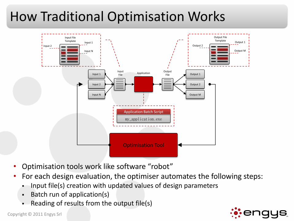
How Traditional Optimisation Works
• Optimisation tools work like software “robot”• For each design evaluation, the optimiser automates the following steps:
Input file(s) creation with updated values of design parameters Batch run of application(s) Reading of results from the output file(s)
Copyright © 2011 Engys Srl
Output 1
Output 2
Output M
Input 1
Input 2
Input N
Input File
Output File
Application
Input File Template
Input 2Input 1
Input N
Output File Template
Output 2Output 1
Output M
my_application.exe
Application Batch Script
Optimisation Tool

Company Details
de
it
Copyright © 2011 Engys Srl
• Registered in UK, Germany and Italy
• CAE services company:
Consultancy
Software & Methods Development
User support & Training
• Open Source engineering software for industry:
CFD → OPENFOAM
Optimisation → DAKOTA
FEM → Code_Aster
• Extensive expertise (> 10 years)
OPENFOAM is a registered trademark of OpenCFD Ltd.

Optimisation Services
• DAKOTA user support & training
• Coupling with most CAE tools OSS, commercial and in-house tools
CFD, FEM, 1D, Multiphysics, Multibody, Manufacturing process simulation, etc
• Design Of Experiments (DOE)
• Multi-objective constrained optimisation
• Model calibration
• Sensitivity analysis
• Tolerance/Robust design
• Model creation for data analysis, prediction, regression and correlation
Copyright © 2011 Engys Srl
CAD
CFD
FEM
Multi-physics
Multi-body
1D
Input 1In
pu
t 2
0 1Output 1

Optimisation Services
• Optimisation: What is the best performing model?• Calibration: What parameter values or models best match a
specific dataset?• Regression / Classification: Which is the value predicted of the
model in different conditions based on an existing dataset?• Sensitivity Analysis: What are the crucial parameters?• Uncertainty Quantification: How safe, reliable, robust, variable
is my system?• Clustering: Are there any similarities among existing samples?
Can the model complexity be reduced?
Input 1
Inp
ut
2
0 1Output 1
Copyright © 2011 Engys Srl

CAD• CATIA V5 • ProENGINEER• Unigraphics NX• SolidWorks• SolidEdge
CFD• OPENFOAM• ANSYS CFX• ANSYS Fluent• STAR-CCM+• STAR-CD
FEM• ABAQUS• ANSYS• LS-Dyna• Madymo• Marc• Nastran
1D• Adams• AVL• Flowmaster• GT-SUITE• MATLAB• Simulink• Wave
Copyright © 2011 Engys Srl
Output 1
Output 2
Output M
Input 1
Input 2
Input N
Input File
Output File
Application
Optimisation Tool
Expertise | Partial List of Coupled Software

Expertise | Optimisation
Copyright © 2011 Engys Srl
Engine charge air cooler tanks optimisationInput Variables14 tank cross-section heightDesign ObjectivesMIN pressure lossesMAX flow uniformityMIN volume of tanks
Best pressure losses
Compromise
Best velocity uniformity
baseline
optimised

Expertise | Model Calibration
• Parameters estimation
• Non linear least-squares methods
• Calibration under uncertainty
→ Ideal for 1D/3D engine models.
Copyright © 2011 Engys Srl
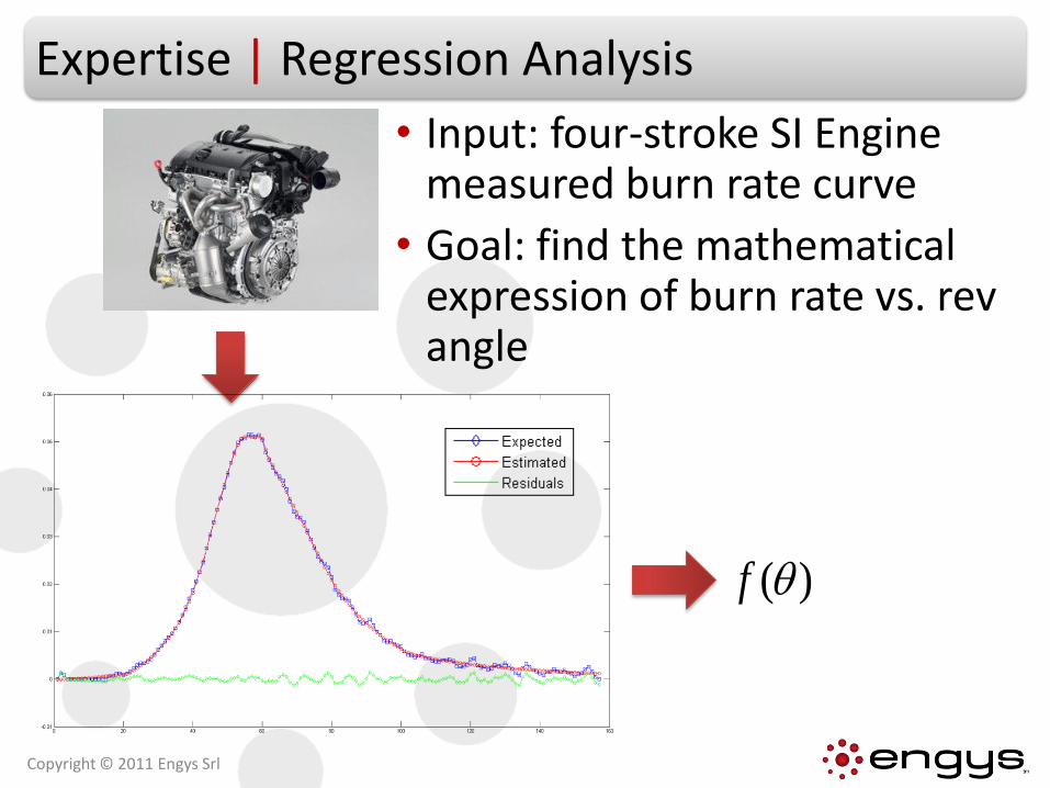
Expertise | Regression Analysis
• Input: four-stroke SI Engine measured burn rate curve
• Goal: find the mathematical expression of burn rate vs. rev angle
)(f
Copyright © 2011 Engys Srl

Contents
• Background
• Example 1: Catalytic Converter Optimisation
• Example 2: Intake Port Optimisation
• Conclusions
Copyright © 2011 Engys Srl

• The optimisation problem can be stated as follows:
• Minimise
and
where:
• Δp is pressures losses between inlet and outlet sections
• Ustdev is a measure of the velocity uniformity at the outlet section
Problem Description
Copyright © 2011 Engys Srl
INLET
OUTLET
PARAMETRIC SHAPE

Geometrical Parameterisation
• CAD geometrical shape parameterisation
• X,Y position of 4 cross-section points
12
34
Different shapes generated
Copyright © 2011 Engys Srl

Parametric CAD model
OpenFOAM | Engys snappyHexMesh
OpenFOAM | Engys caseSetup
OpenFOAM
OpenFOAM + Function objects
Geometry Update
Meshing
Pre-processing
Post-processing
Solver
OPTIMIZER(DAKOTA)
CAD Shape Optimisation Approach
Copyright © 2011 Engys Srl

The Optimisation Workflow
Copyright © 2011 Engys Srl
SnappyHexMeshCAD
DAKOTA
OpenFOAM
Design ParametersInput VariablesX and Y coordinates of 4 cross-section pointsOutput VariablesFlow uniformityPressure drop
Design ObjectivesMaximise flow uniformityMinimise pressure drop
Optimization Setup Exploration Phase:Surrogate-based global MOGA algorithm – max no. of iterations: 10Generation size: 32

Optimisation Results
Copyright © 2011 Engys Srl
BaselineOptimised

Contents
• Background
• Example 1: Catalytic Converter Optimisation
• Example 2: Intake Port Optimisation
• Conclusions
Copyright © 2011 Engys Srl

• The optimisation problem can be stated as follows:
Maximise discharge coefficient, defined as:
Maximise total angular momentum flux (i.e. swirling, tumbling and cross tumbling), whose components are computed as follows:
Problem Description
Copyright © 2011 Engys Srl
INLET
OUTLET
PARAMETRIC SHAPE

Parametric surface morphing model
OpenFOAM | Engys snappyHexMesh
OpenFOAM | Engys caseSetup
OpenFOAM
OpenFOAM + Function objects
Model Update
Meshing
Pre-processing
Post-processing
Solver
OPTIMIZER(DAKOTA)
Surface Morphing Optimisation Approach
Copyright © 2011 Engys Srl

Geometrical Parameterisation
Copyright © 2011 Engys Srl
• Morphing boxes were defined in Blender to perform STL surface morphing of the intake port duct
• 8 degrees of freedom: Y translation of five control points Z translation of three symmetrical control points

Geometrical Parameterisation | Y Translation
dy1 dy2 dy3
dy4 dy5
Copyright © 2011 Engys Srl

Geometrical Parameterisation | Z Translation
Copyright © 2011 Engys Srl
dz1 dz2 dz3

Model Setup | Meshing
• All meshes created with enhanced snappyHexMesh
• Mesh statistics:
Cells: 1,250 K
Wall layers: 5
Max cells size: 19.2 mm
Surface cell size: 0.6-1.2 mm
Min cell size: 0.3 mm
(port arm and valve features)
Copyright © 2011 Engys Srl
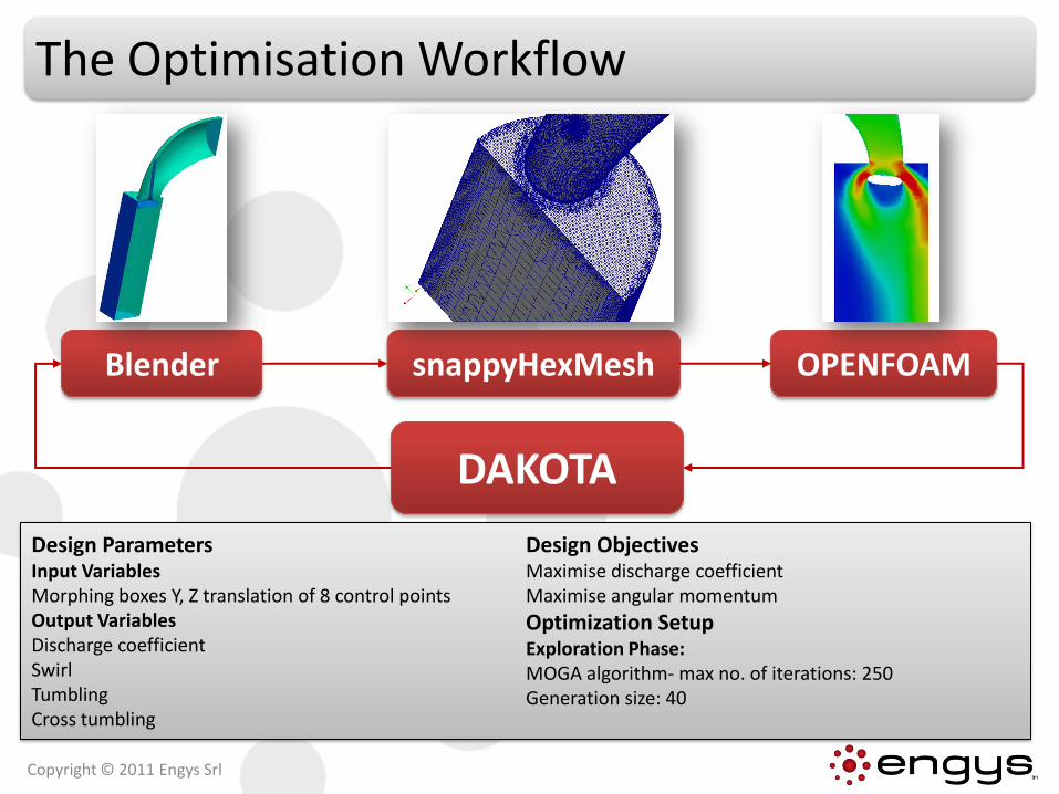
The Optimisation Workflow
snappyHexMeshBlender
DAKOTA
OPENFOAM
Design ParametersInput VariablesMorphing boxes Y, Z translation of 8 control pointsOutput VariablesDischarge coefficientSwirl TumblingCross tumbling
Design ObjectivesMaximise discharge coefficientMaximise angular momentum
Optimization Setup Exploration Phase:MOGA algorithm- max no. of iterations: 250Generation size: 40
Copyright © 2011 Engys Srl

Optimisation Results | Objectives
Copyright © 2011 Engys Srl
Optimised
Baseline

Optimisation Results | Correlation
• Simple Correlation Coefficient is a measure of linear relationship between two variables: +1 indicates two variables positively linearly correlated 0 indicates two variables not correlated -1 indicates two variables negatively linearly correlated
Copyright © 2011 Engys Srl

Optimisation Results | Geometry
Copyright © 2011 Engys Srl
OptimisedBaseline
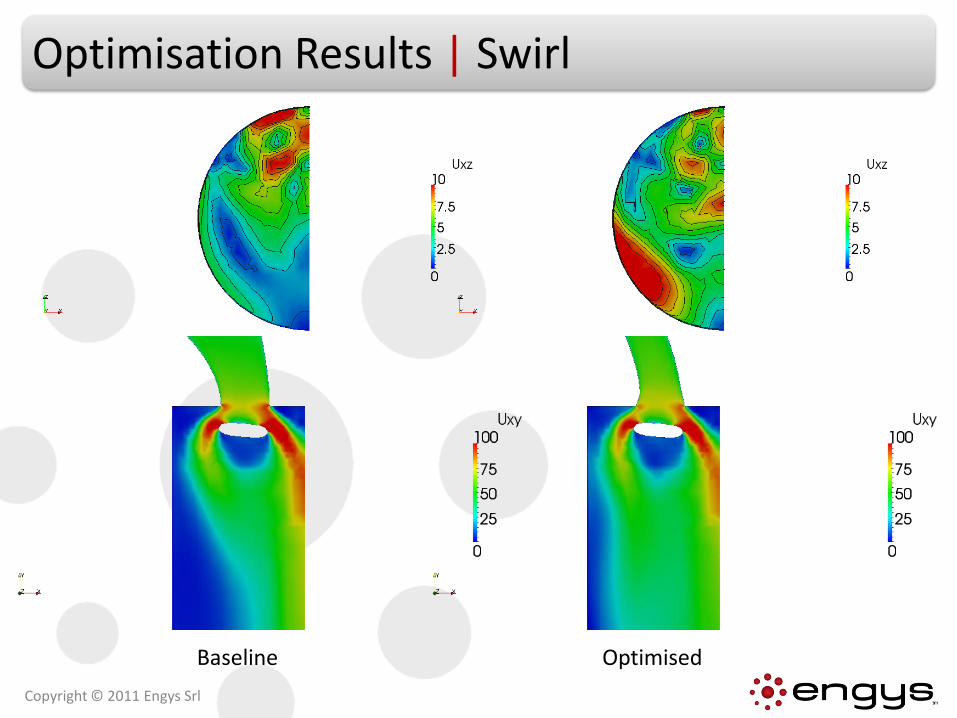
Optimisation Results | Swirl
Optimised
Copyright © 2011 Engys Srl
Baseline

Optimised
Copyright © 2011 Engys Srl
Baseline
Optimisation Results | Discharge Coefficient

Contents
• Background
• Example 1: Catalytic Converter Optimisation
• Example 2: Intake Port Optimisation
• Conclusions
Copyright © 2011 Engys Srl

Conclusions
• The coupling between OSS DAKOTA and OPENFOAM was done successfully.
• Different shape parameterisation techniques were evaluated.
• DAKOTA capabilities were efficiently exploited for different engineering applications.
• Benefits of DAKOTA and OPENFOAM scalability are huge for product development speed-up and reduction in costs.
Copyright © 2011 Engys Srl

THANK YOU VERY MUCH!
QUESTIONS?
Copyright © 2011 Engys Srl