open shortest path first ospf -...
TRANSCRIPT
Open ShortestPath First
OSPFPresented by
Jack Crowder, CCIE

2
Course Outline
• Prerequisites• Routing Protocol Review• Open Shortest Path First
– Overview– Configuration– Troubleshooting– Design

3
Prerequisites
• Familiarity with– Cisco IOS command line– IP addressing and subnetting– Routing Protocols

Introduction toRouting &
Routing ProtocolsPresented by
Jack Crowder, CCIE

5
Routing Intro: Agenda• Purpose• Considerations• Routed Protocol vs. Routing Protocol• Protocol Table vs. Routing Table• Distance Vector vs. Link State Protocols• Comparison Matrix• Building a Routing Table
6
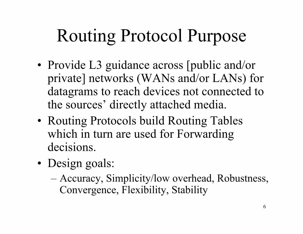
Routing Protocol Purpose• Provide L3 guidance across [public and/or
private] networks (WANs and/or LANs) fordatagrams to reach devices not connected tothe sources’ directly attached media.
• Routing Protocols build Routing Tableswhich in turn are used for Forwardingdecisions.
• Design goals:– Accuracy, Simplicity/low overhead, Robustness,
Convergence, Flexibility, Stability
7
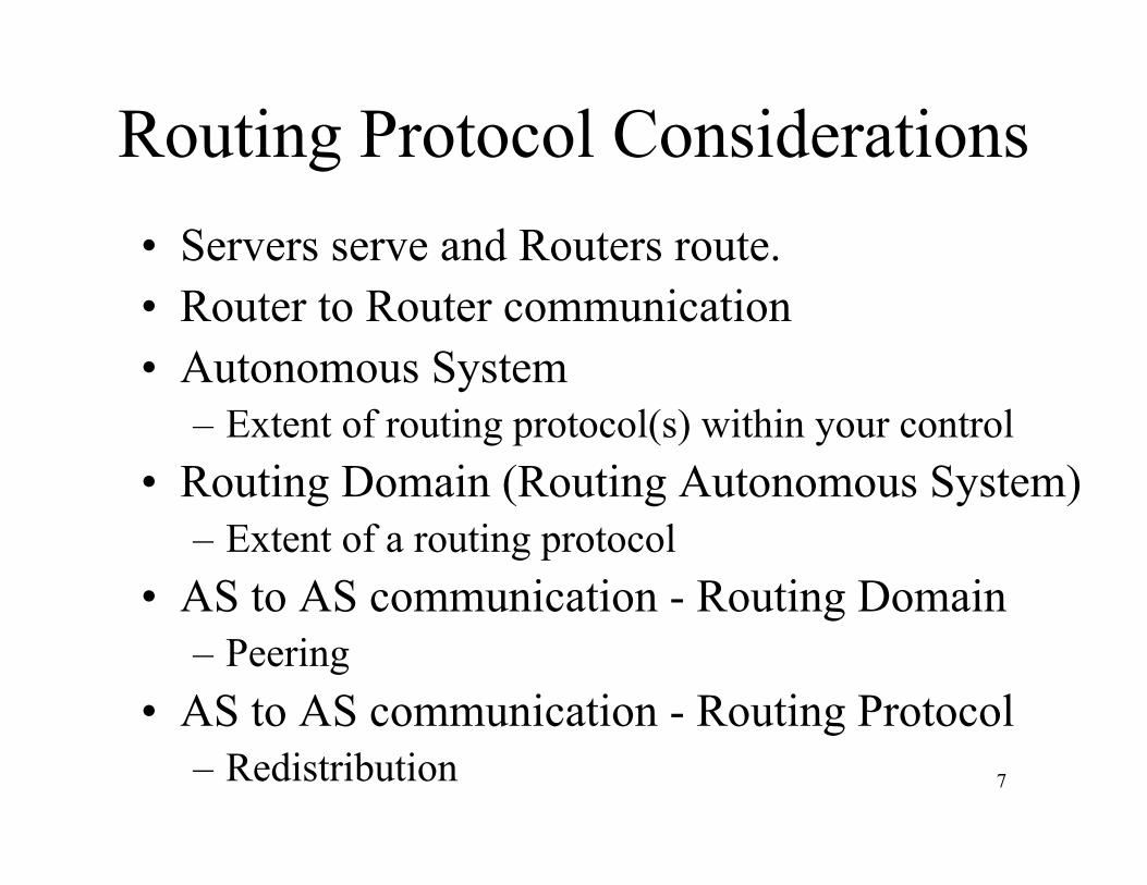
Routing Protocol Considerations• Servers serve and Routers route.• Router to Router communication• Autonomous System
– Extent of routing protocol(s) within your control• Routing Domain (Routing Autonomous System)
– Extent of a routing protocol• AS to AS communication - Routing Domain
– Peering• AS to AS communication - Routing Protocol
– Redistribution
8
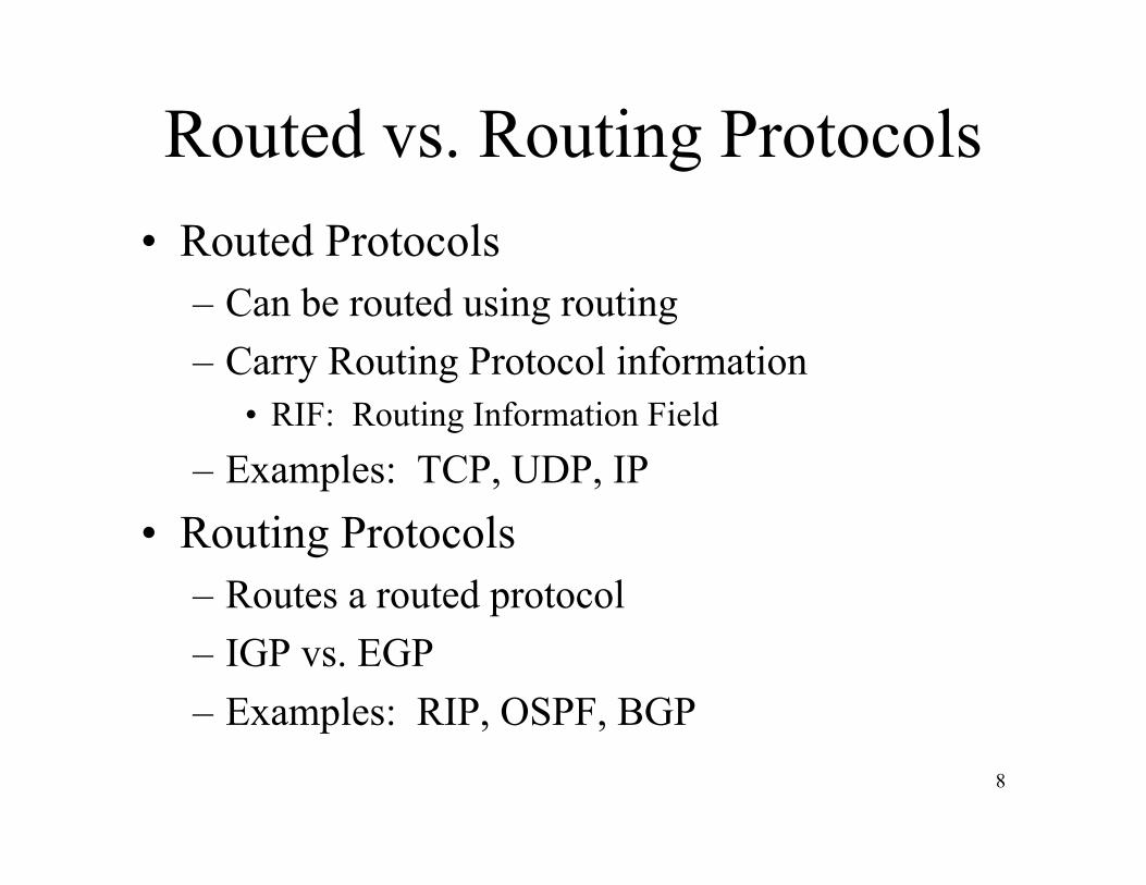
• Routed Protocols– Can be routed using routing– Carry Routing Protocol information
• RIF: Routing Information Field– Examples: TCP, UDP, IP
• Routing Protocols– Routes a routed protocol– IGP vs. EGP– Examples: RIP, OSPF, BGP
Routed vs. Routing Protocols

9
ROUTING
TABLE
CONNECTED
ROUTES
STATIC
ROUTES
BGP
ROUTES
eBGPOSPF
ROUTES
BGP
ROUTES
iBGP
SPF
Metrics
ADMINISTRATIVE
DISTANCE
CACHE
TABLE
Protocol Table vs. Routing Table

10
Routing Concepts• Destination/Next Hop Association
– To reach a destination, send packet to next hop• Destination/Metric Association
– To reach a destination, send packet to next hopwith lowest metric
• Destination/Path Association– To reach a destination, send packet along a
certain path• Metrics: Reliability, Delay, Bandwidth,
Load, MTU, Communication cost
11
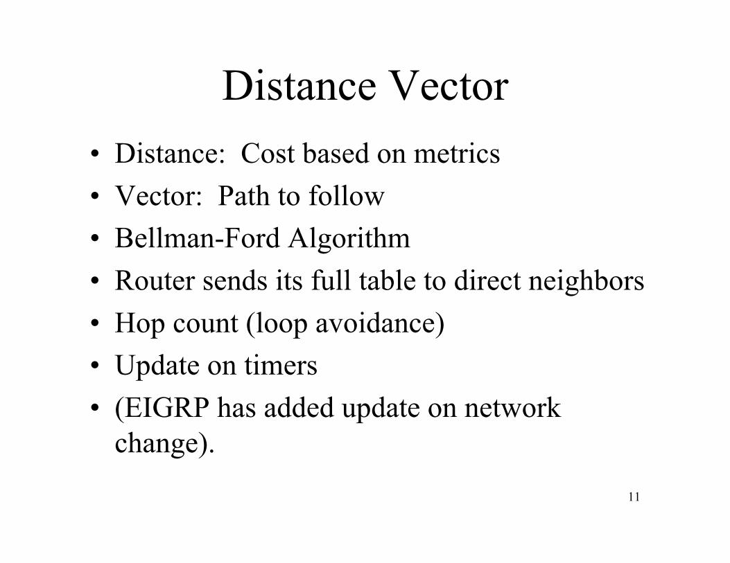
Distance Vector• Distance: Cost based on metrics• Vector: Path to follow• Bellman-Ford Algorithm• Router sends its full table to direct neighbors• Hop count (loop avoidance)• Update on timers• (EIGRP has added update on network
change).

12
Link State• Shortest Path First• Dijkstra Algorithm• Each router sends its state to all other routers• Every router has topology (database) of entire
network• Update on link change• Faster convergence/Higher CPU requirements
13
summ: 5
int: 90
ext: 170
RIP
EIG
RP
OS
PF
sta
tic
IS-I
S
Link
State
DistanceVector
EGP
IGP
Admin
Distance
X
120 115110
interface: 0
next hop: 1
floating: ?
BG
P
XXX
X
X
XX
X
X iBGP
eBGP
X
X
X
X

14
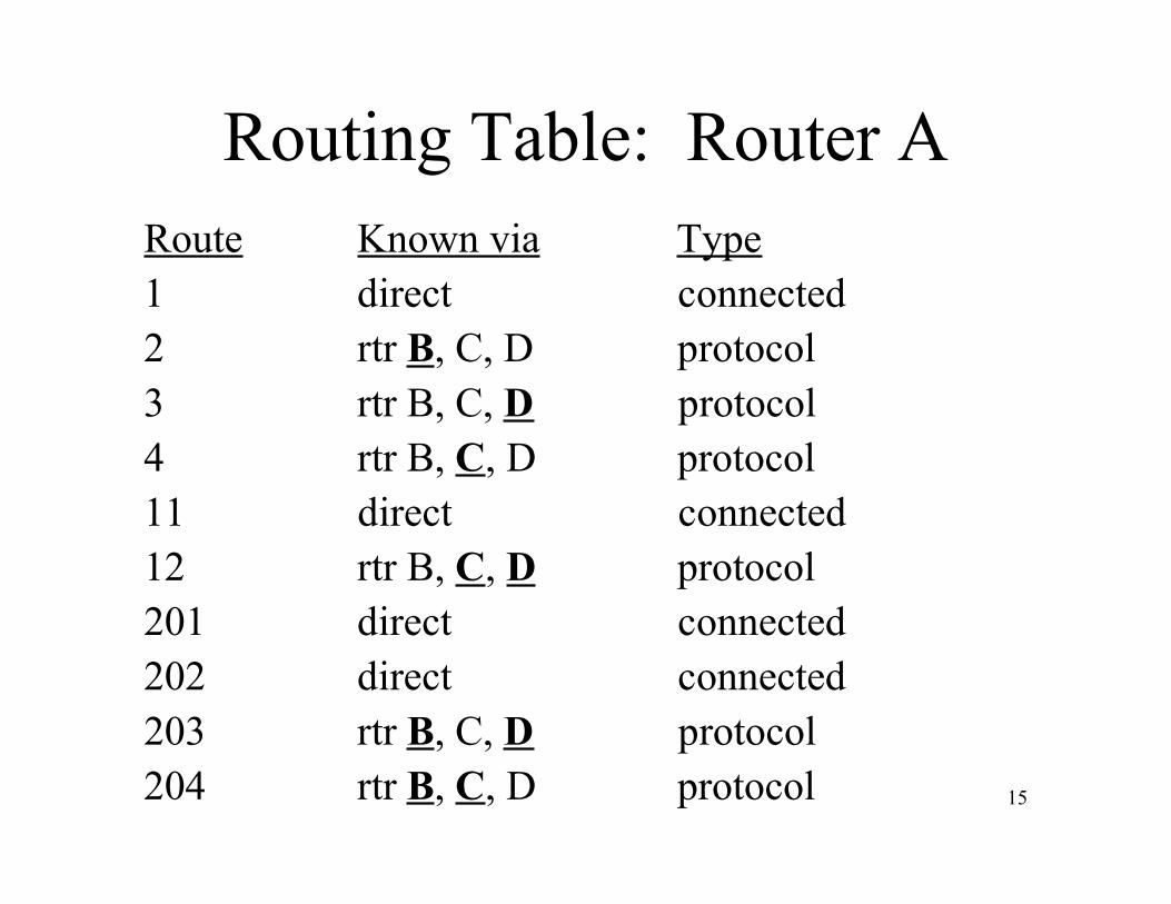
Topology
A D
CB
11
4
3
2
1
203
202
12
204
201
15
Routing Table: Router ARoute Known via Type1 direct connected2 rtr B, C, D protocol3 rtr B, C, D protocol4 rtr B, C, D protocol11 direct connected12 rtr B, C, D protocol201 direct connected202 direct connected203 rtr B, C, D protocol204 rtr B, C, D protocol

16
Routing Protocol: OSPF• Overview
– what is it
• Configuration– how is it
• Troubleshooting– why is it
• Design– how, why and where to use it

Part 1Overview

18
OSPF Overview
• Open Shortest Path First– RFC1131, J. Moy, Oct-1989– Cisco introduced in IOS v9.0 March-1990
• What is OSPF?• Why you should use OSPF?• Where would you use OSPF?

19
What is OSPF?
• IGP (Interior Gateway Protocol)• Link State Protocol
– Database (Topology)– Shortest Path First (SPF or Dijkstra) algorithm– Update on link state change
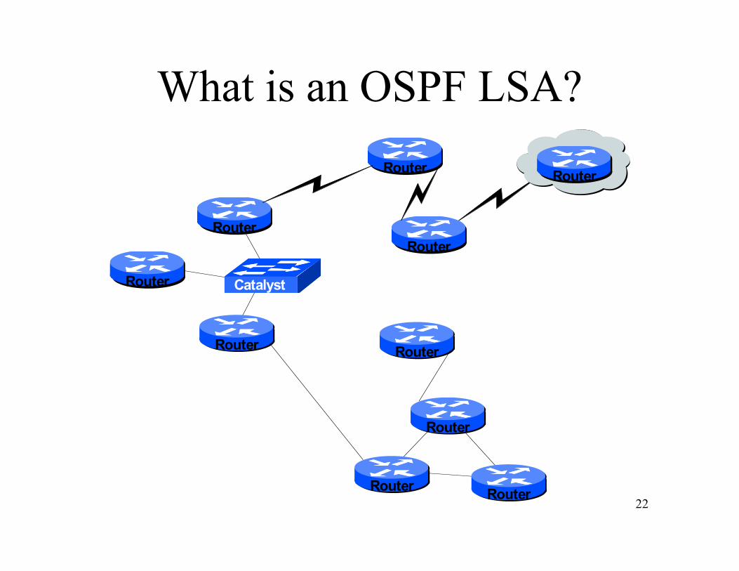
• Areas• Neighbors• Link State Advertisements (LSA)

20
What is an OSPF Area?
Router
Catalyst
Router
Router
Router
Router
Router
Router
RouterRouter
Router
21
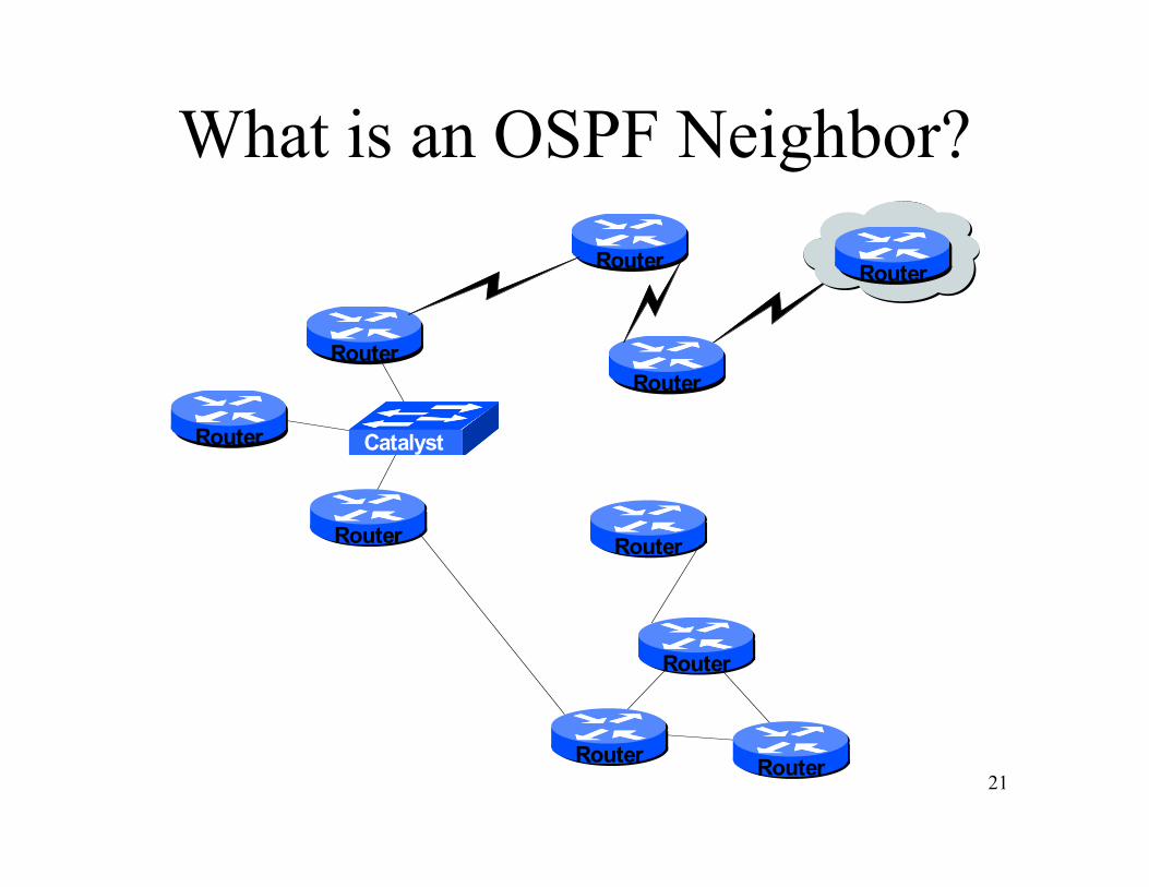
What is an OSPF Neighbor?
Router
Catalyst
Router
Router
Router
Router
Router
Router
RouterRouter
Router
22
What is an OSPF LSA?
Router
Catalyst
Router
Router
Router
Router
Router
Router
RouterRouter
Router

23
Why you should use OSPF?• Mostly widely deployed on the Enterprise
and Tier 2/3 Service Providers– Deployed in networks– Deployed by vendors
• Hardware supportability– Memory and processors are cheap– Each router knows about the entire topology
• Scalability– Recalculation upon change– Change restricted to Area

24
Where would you use OSPF?
• Clearly define the backbone Area 0– Think Hub and spoke
• Areas based on traffic flows– Therein lies it’s one scalability issue
• Consider stability of links– Not for Remote Access Servers– (There is an OSPF DDR mechanism).

LAB 1:Setup and Familiarization
Purpose: Review Physical connectivity

Part 2Configuration

27
OSPF Configuration• Global
– Router OSPF <process-id>• Interface
– LAN, WAN, Dial-up• Protocol
– Area– Neighbor– Link State Advertisements– Network Announcements

28
OSPF Protocol Configuration• Area
– Backbone (0)– Types: Intra, Inter, Stub, NSSA, TSA
• Neighbor– Adjacencies
• Non-Broadcast Multi Access (NBMA)• Point-to-Point
• Link State Advertisements– Network, Router, Summary, External
• Network Announcements– Aggregation

29
Global Configurationrouter OSPF <1-65535> (Process ID) area OSPF area parameters auto-cost Calculate interface cost according to bandwidth capability Enable specific OSPF feature default Set a command to its defaults default-informationControl distribution of default information default-metric Set metric of redistributed routes distance Define an administrative distance distribute-list Filter networks in routing updates ignore Do not complain about specific event log-adjacency-changes Log changes in adjacency state

30
Global Configurationrouter OSPF <1-65535> (Process ID) maximum-paths Forward packets over multiple paths neighbor Specify a neighbor router network Enable routing on an IP network passive-interface Suppress routing updates on an interface redistribute Redistribute information from another
routing protocol router-id router-id for this OSPF process summary-address Configure IP address summaries timers Adjust routing timers traffic-share How to compute traffic share over alternate
paths
31
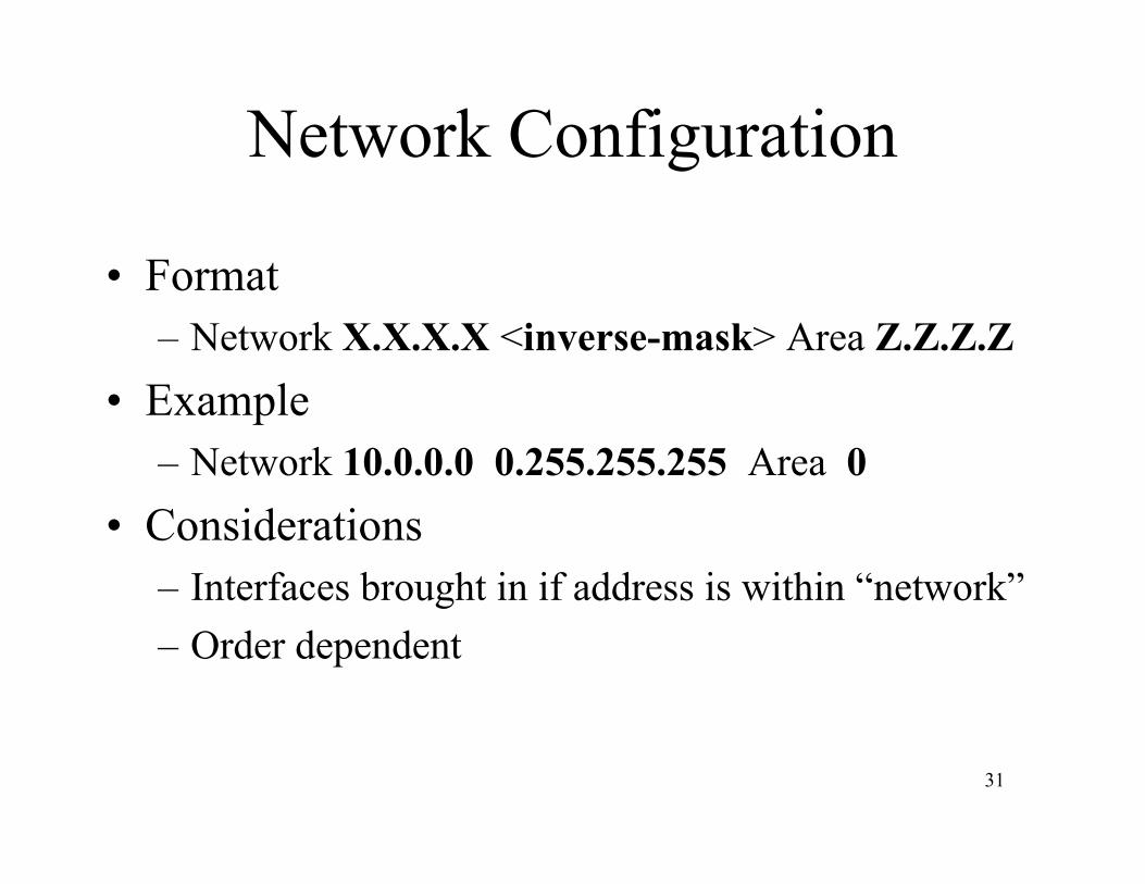
Network Configuration
• Format– Network X.X.X.X <inverse-mask> Area Z.Z.Z.Z
• Example– Network 10.0.0.0 0.255.255.255 Area 0
• Considerations– Interfaces brought in if address is within “network”– Order dependent
32
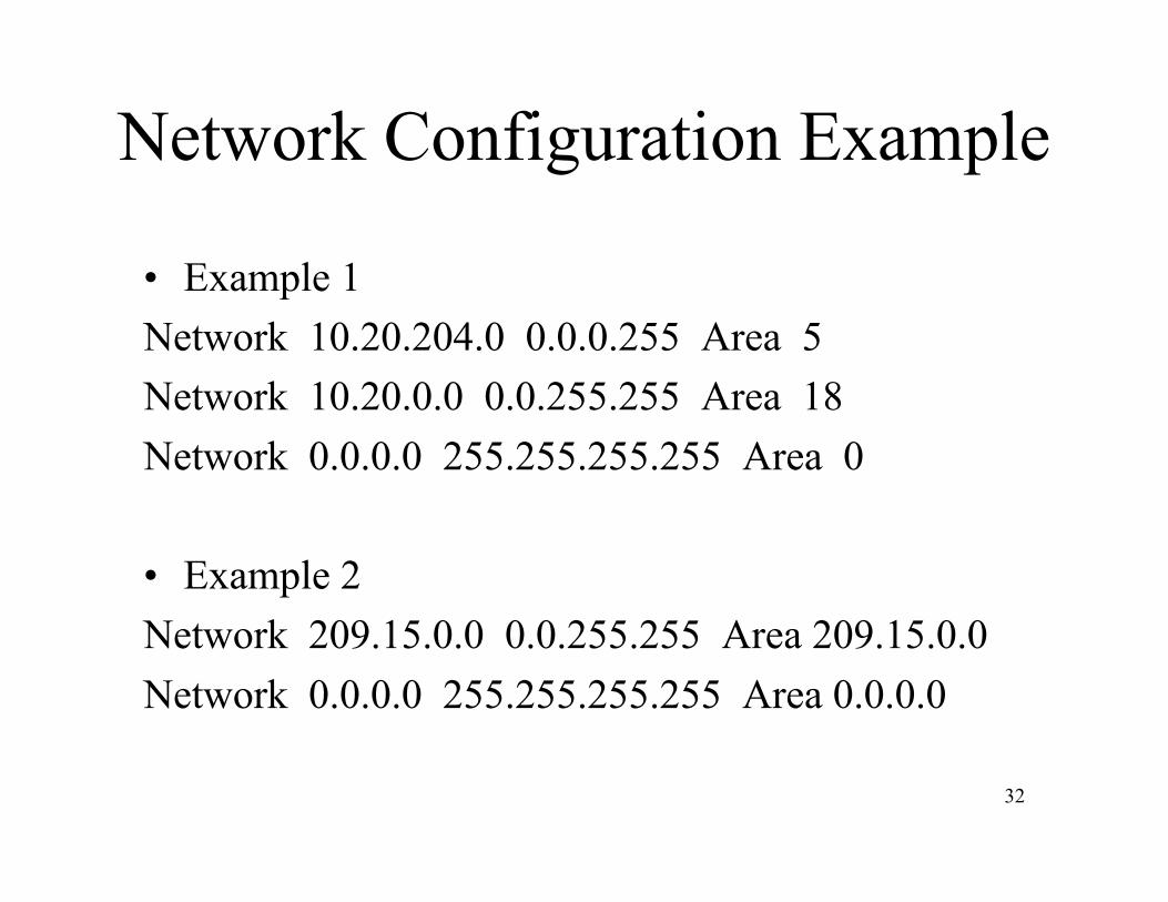
Network Configuration Example
• Example 1Network 10.20.204.0 0.0.0.255 Area 5Network 10.20.0.0 0.0.255.255 Area 18Network 0.0.0.0 255.255.255.255 Area 0
• Example 2Network 209.15.0.0 0.0.255.255 Area 209.15.0.0Network 0.0.0.0 255.255.255.255 Area 0.0.0.0

33
Example Configuration• COR1.pdx• router ospf 4540• network 207.170.192.50 0.0.0.0 area 0• network 207.170.193.1 0.0.0.0 area 0• network 207.170.193.161 0.0.0.0 area 1• network 207.170.193.177 0.0.0.0 area 1• network 207.170.198.1 0.0.0.0 area 0• network 207.170.198.89 0.0.0.0 area 0• network 207.170.198.93 0.0.0.0 area 0• network 207.170.198.97 0.0.0.0 area 0• network 207.170.198.101 0.0.0.0 area 0• network 207.170.198.105 0.0.0.0 area 0• network 207.170.198.109 0.0.0.0 area 0• network 207.170.198.125 0.0.0.0 area 0• network 207.170.198.133 0.0.0.0 area 0• log-adjacency-changes
• AGR4.pdx• router ospf 4540• network 206.169.236.1 0.0.0.0 area 1• network 207.170.193.164 0.0.0.0 area 1• network 207.170.193.180 0.0.0.0 area 1• network 207.170.192.46 0.0.0.0 area 1• log-adjacency-changes
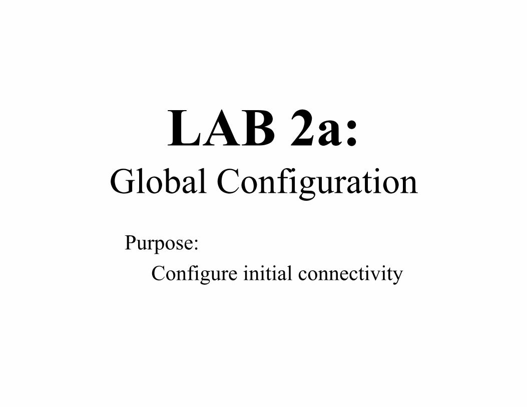
LAB 2a:Global Configuration
Purpose: Configure initial connectivity

35
Neighbor Adjacency
• Two neighbors must be configured:– On same IP subnet (even though multicast is used)
• Multicast address 224.0.0.5 and 224.0.0.6 is used– Same area number– Timers (HelloInterval and DeadInterval) must
match• Timer information is sent in packet
Router Router

36
Interface ConfigurationIP OSPF authentication-key Authentication password (key) cost Interface cost database-filter Filter LSA during synchronization / flooding dead-interval Interval after which neighbor is declared dead demand-circuit OSPF demand circuit hello-interval Time between HELLO packets message-digest-key Message digest authentication password network Network type priority Router priority retransmit-interval Time between retransmitting lost link state
advertisements transmit-delay Link state transmit delay

37
OSPF Metric Calculation
• Default Metric (Cost) = 100,000,000/bandwidth– bandwidth shown on interface (default can be changed)
• Cost can be changed– Manually configured on an interface: ip ospf cost xx– Globally configured: ospf auto-cost reference-bandwidth
cor1.pdx> sh ip route ospf
O IA 207.170.192.25/32 [110/30] via 207.170.198.94, 01:00:33, ATM1/0/0.101O 207.170.192.26/32 [110/2] via 207.170.193.163, 3w2d, FastEthernet1/1/0O E2 209.234.154.0/24 [110/20] via 207.170.198.94, 01:00:33, ATM1/0/0.101

38
Route Cost Calculation
Router Router Router
BW=100,000,000BW=1,500,000
BW=10,000,000
Cost =
Cost =
Cost =
Total Cost =
LAB 2b:Interface Configuration
Purpose:Observe the effect ofchanging interface parameters

40
Areas• Backbone - Area 0
– Contiguous– No full-mesh requirements
• All AREAs touch Area 0 and *NO* other area– Virtual links can “heal” this
• All AREAs are contiguous– Virtual links can “heal” this
• Area types:– Normal (default) - Stub– NSSA - TSA

41
Area Configuration
Router OSPF <1-65535> (Process ID) area <0-4294967295> or A.B.C.D
authentication Enable authenticationdefault-cost Set summary default-cost of NSSA/stub areanssa Specify a NSSA arearange Summarize routes matching address/mask
(border routers only)stub Specify a Stub Area no-summary Specify a Totally Stubby Areavirtual-link Define a virtual link and its parameters

42
Backbone Area 0 / Normal Area X
Router Router
AREA 0
AREA 201AREA 51
STUB
Router
Router
Router
AREA 1

43
Route Types: Internal• Intra Area
– Designated “O”– Flows within an area– Is converted to type Inter-Area upon area exit
• Inter Area– Designated “O IA”– Can be summarized at Area Boundary (on ABR)
44
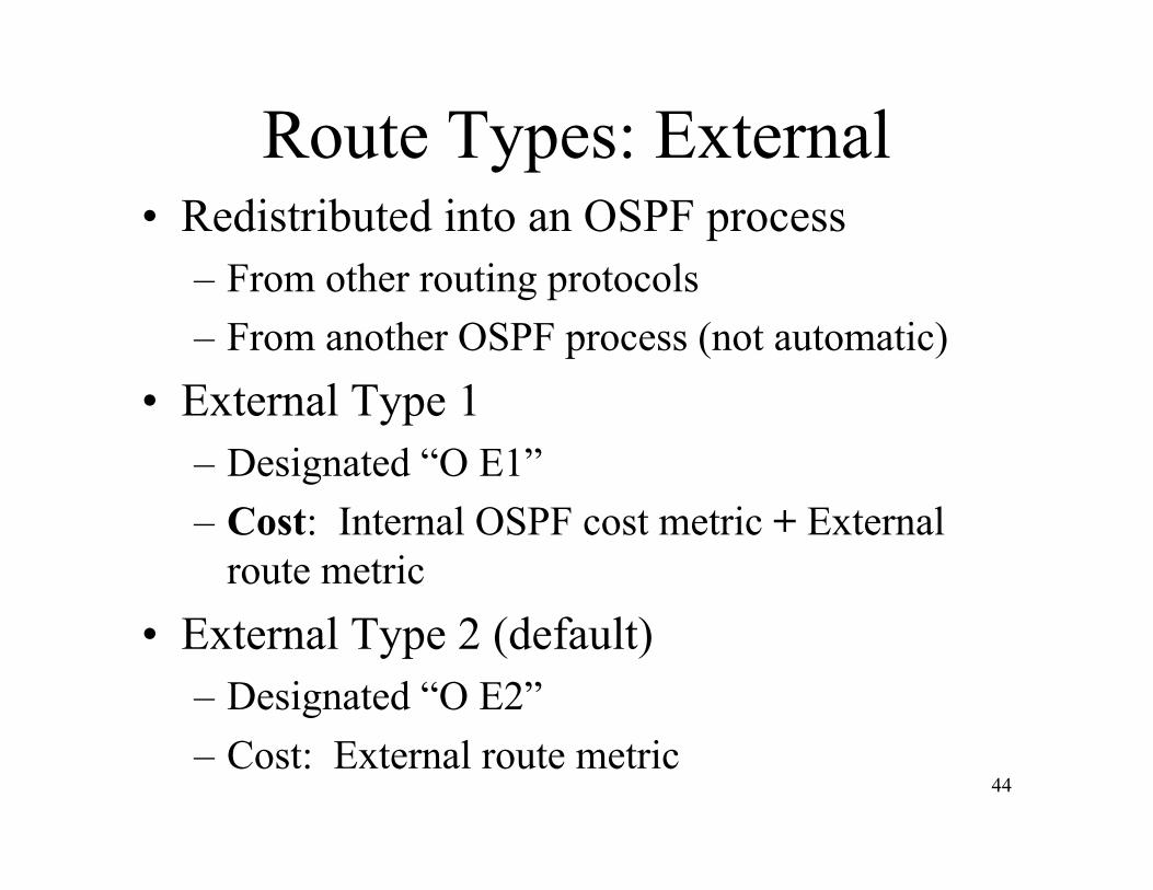
Route Types: External• Redistributed into an OSPF process
– From other routing protocols– From another OSPF process (not automatic)
• External Type 1– Designated “O E1”– Cost: Internal OSPF cost metric + External
route metric• External Type 2 (default)
– Designated “O E2”– Cost: External route metric

LAB 2c:Area X Configuration
Purpose: Configure multiple [NORMAL] Areas

46
Stub Area
LAB 2d:Area X Configuration
Purpose: Configure multiple [STUB] Areas
48
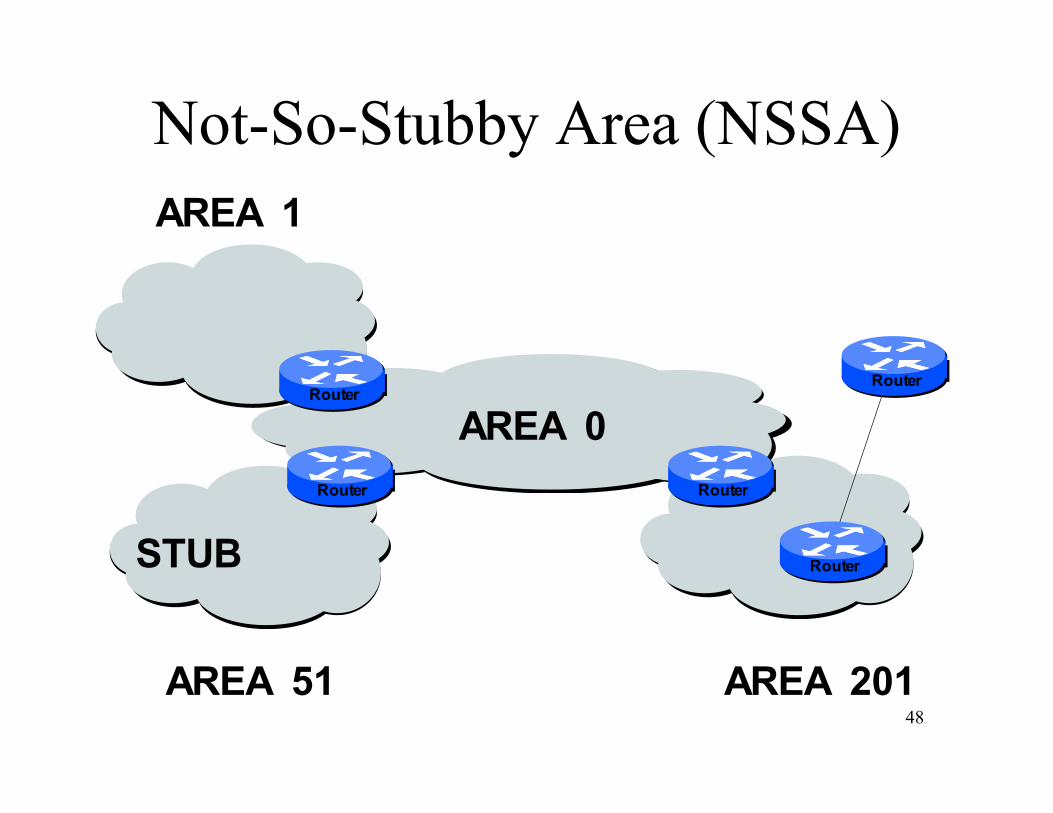
Not-So-Stubby Area (NSSA)
Router Router
AREA 0
AREA 201AREA 51
STUB
Router
Router
Router
AREA 1
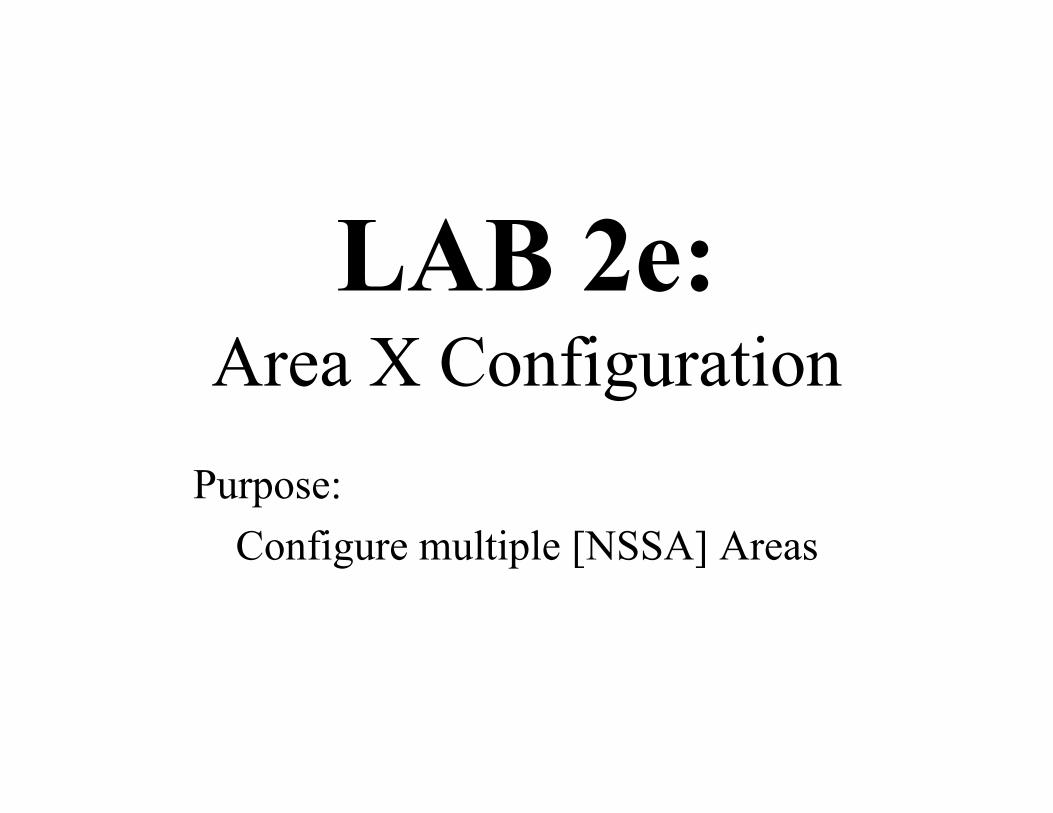
LAB 2e:Area X Configuration
Purpose: Configure multiple [NSSA] Areas

50
Totally-Stubby Area (TSA)
Router Router
AREA 0
AREA 201AREA 51
STUB
Router
Router
Router
AREA 1

LAB 2f:Area X Configuration
Purpose: Configure multiple [TSA] Areas
52
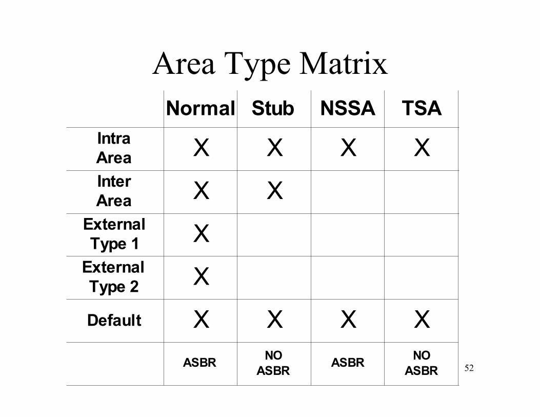
Area Type MatrixTSANormal Stub NSSA
Intra
Area
External
Type 2
External
Type 1
Inter
Area
X XXX
X
X
X
X
Default X X XX
ASBR ASBRNO
ASBR
NO
ASBR

53
Neighbors• Adjacencies:
– Rules– Timers– Sequence
• Media Types:– Broadcast Multi Access– Non-Broadcast Multi Access
• Point to Multi-Point– Point to Point
• Link State Advertisements– Type 1 through 10
54
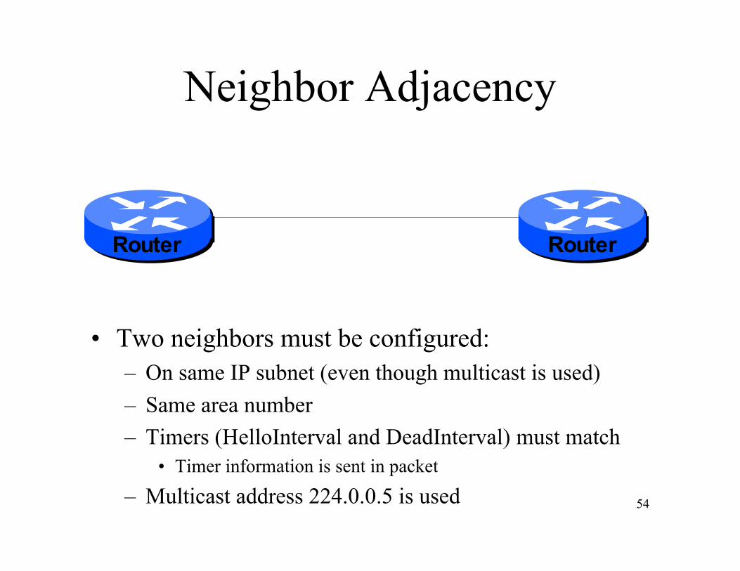
Neighbor Adjacency
• Two neighbors must be configured:– On same IP subnet (even though multicast is used)– Same area number– Timers (HelloInterval and DeadInterval) must match
• Timer information is sent in packet
– Multicast address 224.0.0.5 is used
Router Router
55
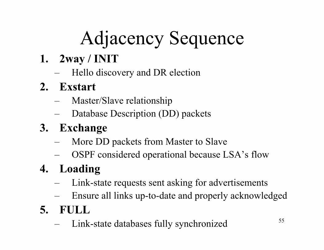
Adjacency Sequence1. 2way / INIT
– Hello discovery and DR election2. Exstart
– Master/Slave relationship– Database Description (DD) packets
3. Exchange– More DD packets from Master to Slave– OSPF considered operational because LSA’s flow
4. Loading– Link-state requests sent asking for advertisements– Ensure all links up-to-date and properly acknowledged
5. FULL– Link-state databases fully synchronized
56
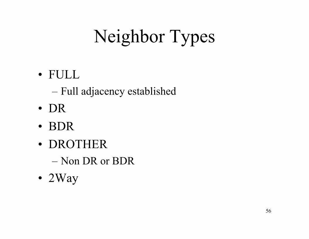
Neighbor Types
• FULL– Full adjacency established
• DR• BDR• DROTHER
– Non DR or BDR• 2Way
57
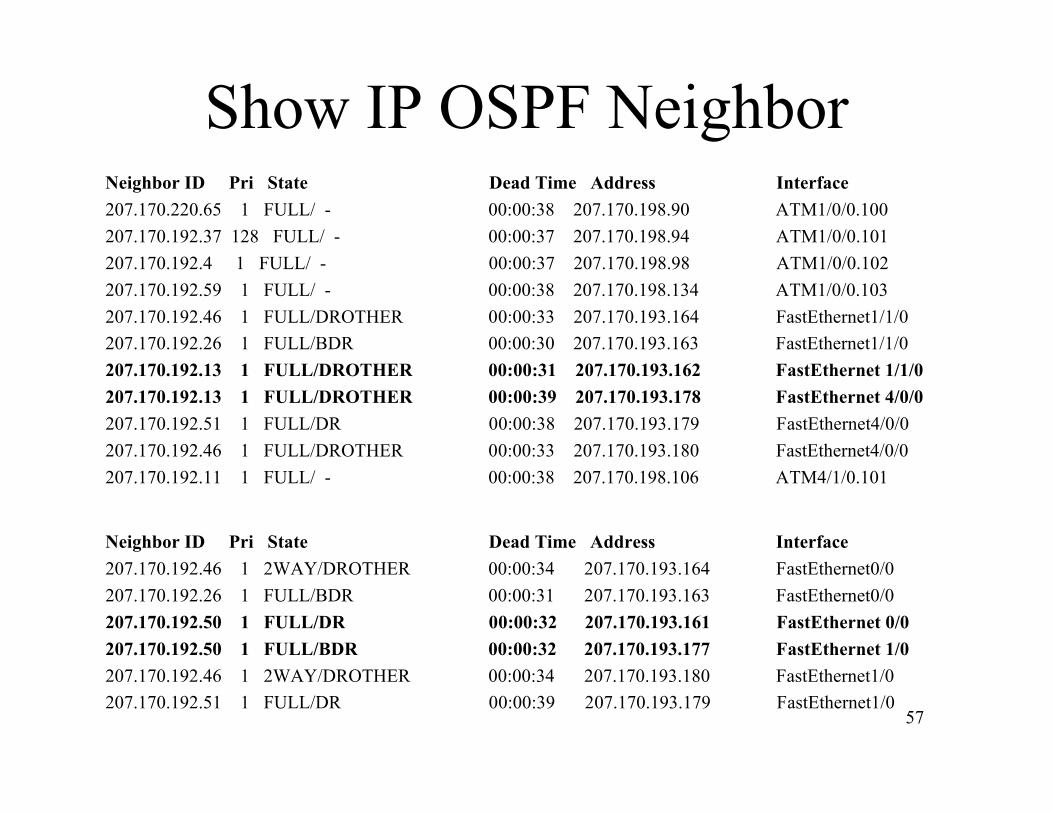
Show IP OSPF NeighborNeighbor ID Pri State Dead Time Address Interface207.170.220.65 1 FULL/ - 00:00:38 207.170.198.90 ATM1/0/0.100207.170.192.37 128 FULL/ - 00:00:37 207.170.198.94 ATM1/0/0.101207.170.192.4 1 FULL/ - 00:00:37 207.170.198.98 ATM1/0/0.102207.170.192.59 1 FULL/ - 00:00:38 207.170.198.134 ATM1/0/0.103207.170.192.46 1 FULL/DROTHER 00:00:33 207.170.193.164 FastEthernet1/1/0207.170.192.26 1 FULL/BDR 00:00:30 207.170.193.163 FastEthernet1/1/0207.170.192.13 1 FULL/DROTHER 00:00:31 207.170.193.162 FastEthernet 1/1/0207.170.192.13 1 FULL/DROTHER 00:00:39 207.170.193.178 FastEthernet 4/0/0207.170.192.51 1 FULL/DR 00:00:38 207.170.193.179 FastEthernet4/0/0207.170.192.46 1 FULL/DROTHER 00:00:33 207.170.193.180 FastEthernet4/0/0207.170.192.11 1 FULL/ - 00:00:38 207.170.198.106 ATM4/1/0.101
Neighbor ID Pri State Dead Time Address Interface207.170.192.46 1 2WAY/DROTHER 00:00:34 207.170.193.164 FastEthernet0/0207.170.192.26 1 FULL/BDR 00:00:31 207.170.193.163 FastEthernet0/0207.170.192.50 1 FULL/DR 00:00:32 207.170.193.161 FastEthernet 0/0207.170.192.50 1 FULL/BDR 00:00:32 207.170.193.177 FastEthernet 1/0207.170.192.46 1 2WAY/DROTHER 00:00:34 207.170.193.180 FastEthernet1/0207.170.192.51 1 FULL/DR 00:00:39 207.170.193.179 FastEthernet1/0
58
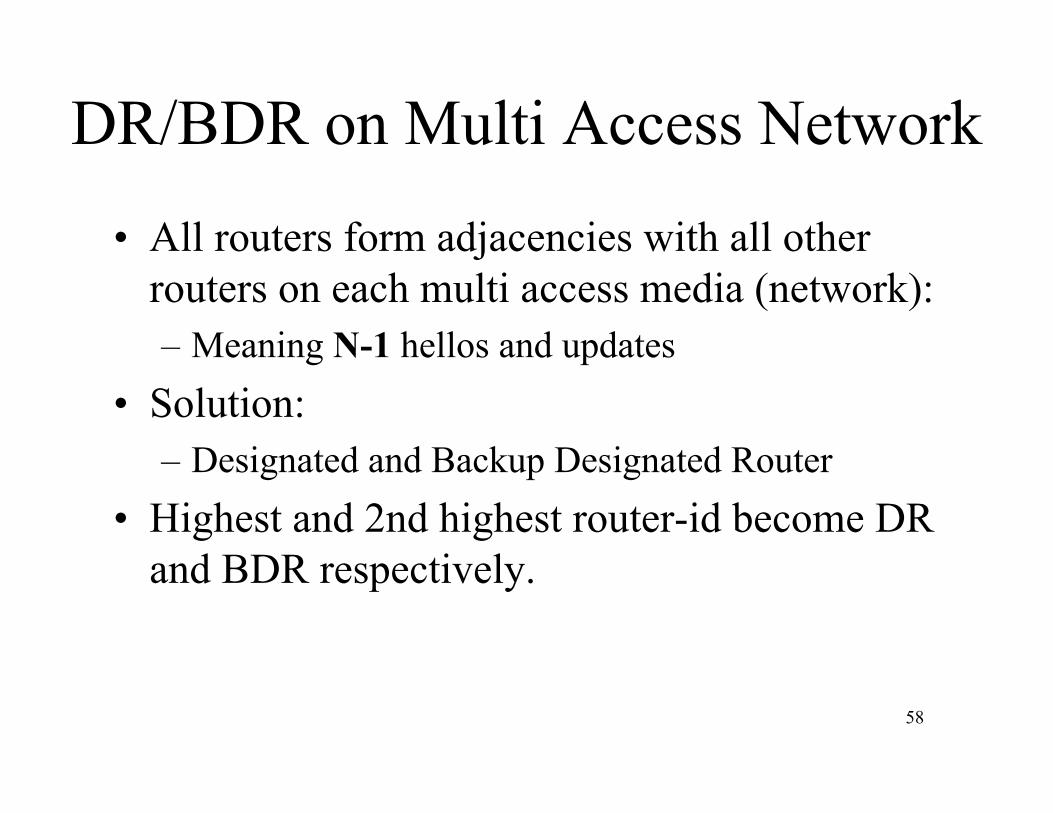
DR/BDR on Multi Access Network
• All routers form adjacencies with all otherrouters on each multi access media (network):– Meaning N-1 hellos and updates
• Solution:– Designated and Backup Designated Router
• Highest and 2nd highest router-id become DRand BDR respectively.
59
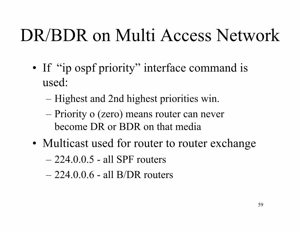
DR/BDR on Multi Access Network
• If “ip ospf priority” interface command isused:– Highest and 2nd highest priorities win.– Priority o (zero) means router can never
become DR or BDR on that media• Multicast used for router to router exchange
– 224.0.0.5 - all SPF routers– 224.0.0.6 - all B/DR routers

60
DR and BDR Election
Router Router
RouterRouterRouter
LAB 2g:DR and BDR Configuration
Purpose: Configure DR and BDR on MultiAccess media
62
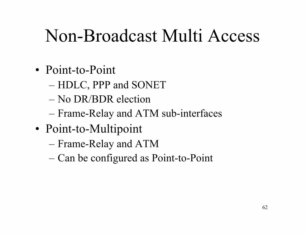
Non-Broadcast Multi Access
• Point-to-Point– HDLC, PPP and SONET– No DR/BDR election– Frame-Relay and ATM sub-interfaces
• Point-to-Multipoint– Frame-Relay and ATM– Can be configured as Point-to-Point
63
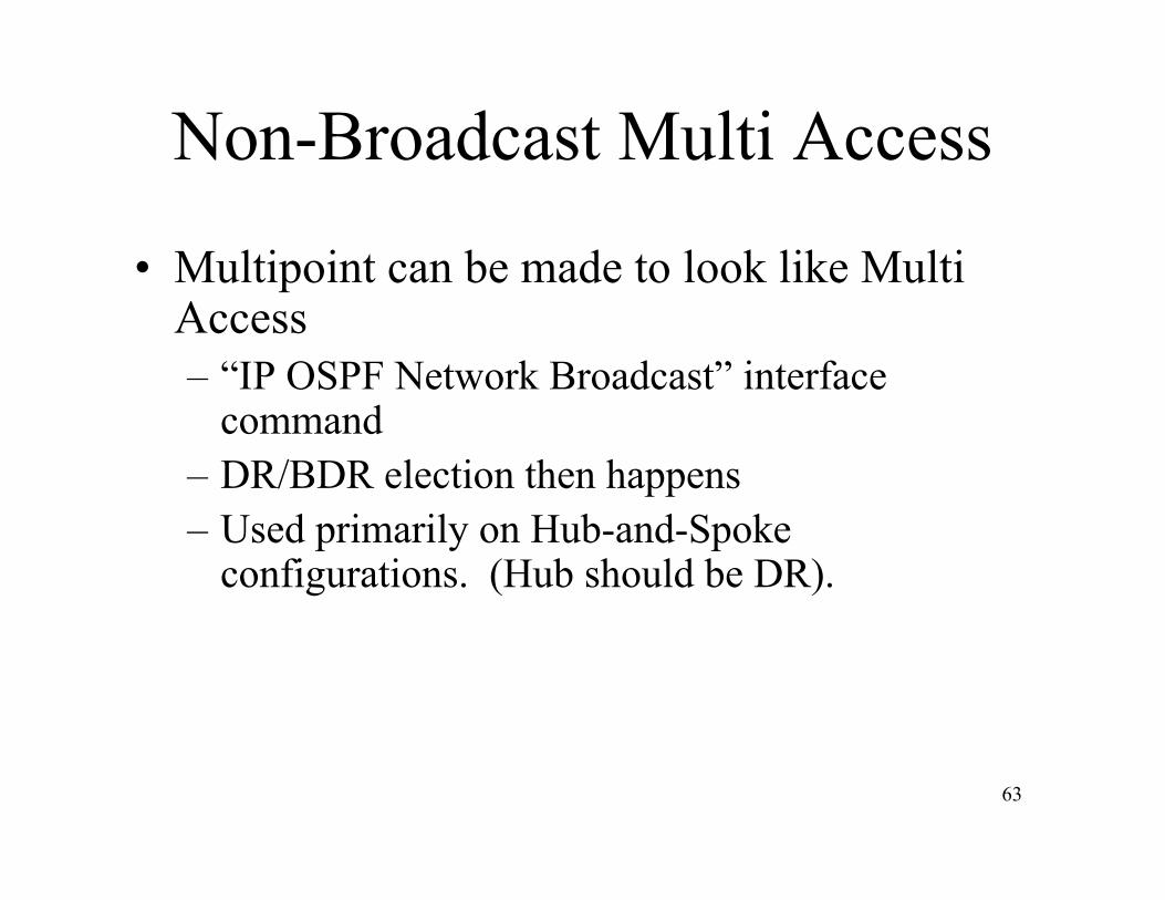
Non-Broadcast Multi Access
• Multipoint can be made to look like MultiAccess– “IP OSPF Network Broadcast” interface
command– DR/BDR election then happens– Used primarily on Hub-and-Spoke
configurations. (Hub should be DR).

LAB 2h:Neighbor ConfigurationPurpose: Configure neighbors on NBMA media

65
LSA Packet Type1. Router LSA
– Generated by each router for each area it belongs– Describe the state of router’s links– Flooded within area only
2. Network LSA– Generated by Designated Router– Flooded within area containing network– Link-state ID is the interface IP address of DR
3. Summary LSA (ABR)– Generated by Area Border Router– Describe Inter-Area (IA) routes– Can be used for aggregation– Link-state ID is the destination network number
66
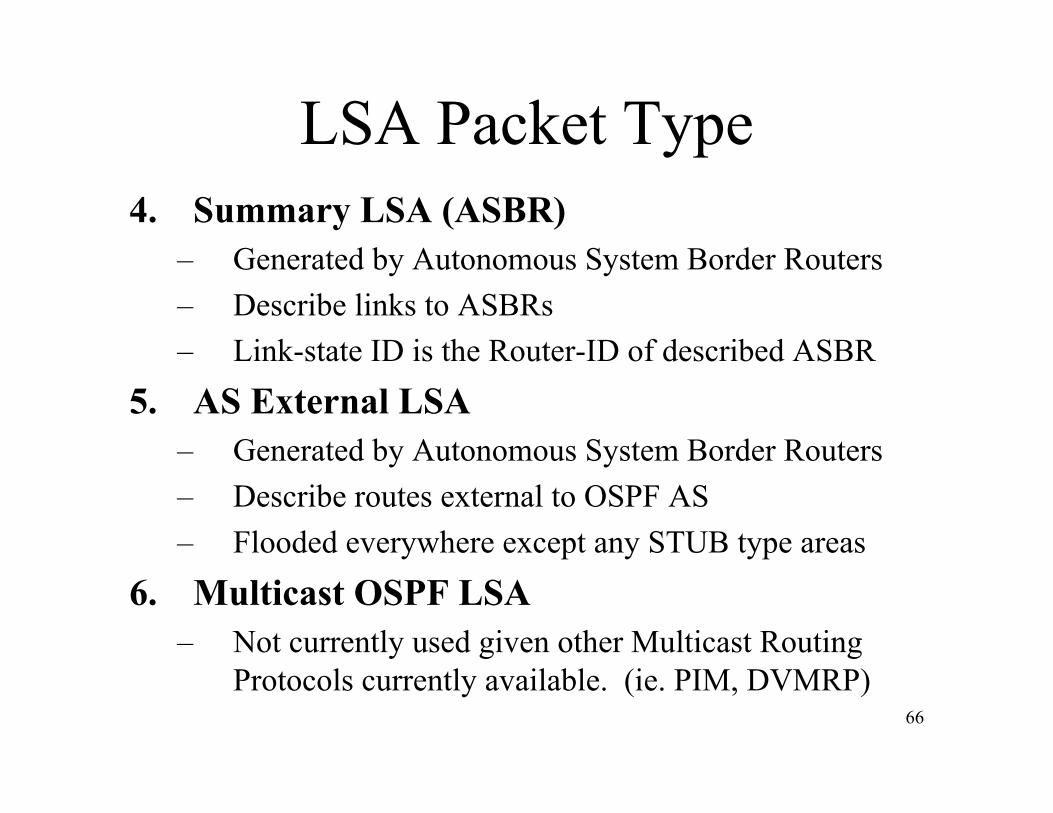
LSA Packet Type4. Summary LSA (ASBR)
– Generated by Autonomous System Border Routers– Describe links to ASBRs– Link-state ID is the Router-ID of described ASBR
5. AS External LSA– Generated by Autonomous System Border Routers– Describe routes external to OSPF AS– Flooded everywhere except any STUB type areas
6. Multicast OSPF LSA– Not currently used given other Multicast Routing
Protocols currently available. (ie. PIM, DVMRP)

67
LSA Packet Type7. Not-So-Stubby-Area LSA
– RFC 1587– Generated by Autonomous System Border Routers– Describe external routes within an NSSA– Can be converted into Type 5 LSA
8.,9.,10. Reserved
68
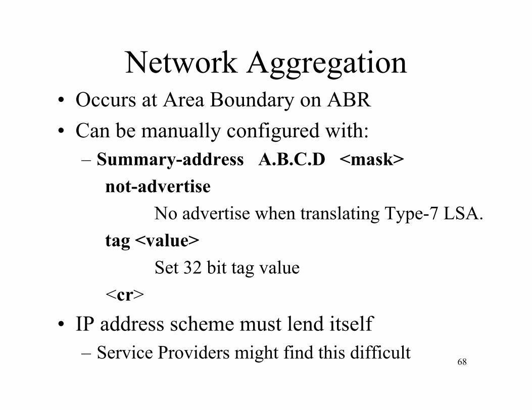
Network Aggregation• Occurs at Area Boundary on ABR• Can be manually configured with:
– Summary-address A.B.C.D <mask> not-advertise
No advertise when translating Type-7 LSA. tag <value>
Set 32 bit tag value<cr>
• IP address scheme must lend itself– Service Providers might find this difficult
LAB 2i:Neighbor ConfigurationPurpose: Configure aggregation for areaannouncement.

Part 3Troubleshooting

71
OSPF Troubleshooting• Example Network• Show
– Commands– Output
• Debug– Commands– Output
72
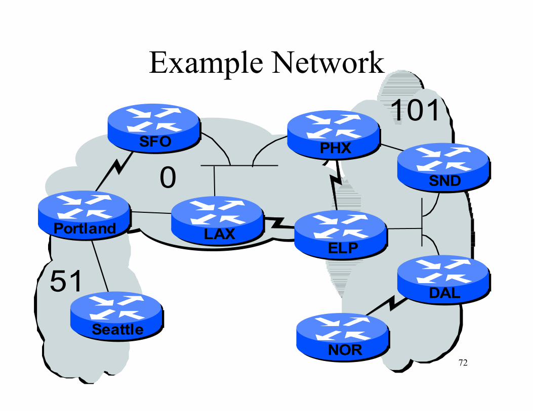
Example Network
0
101
51
NOR
SND
DAL
ELP
Portland
Seattle
SFO
LAX
PHX
73
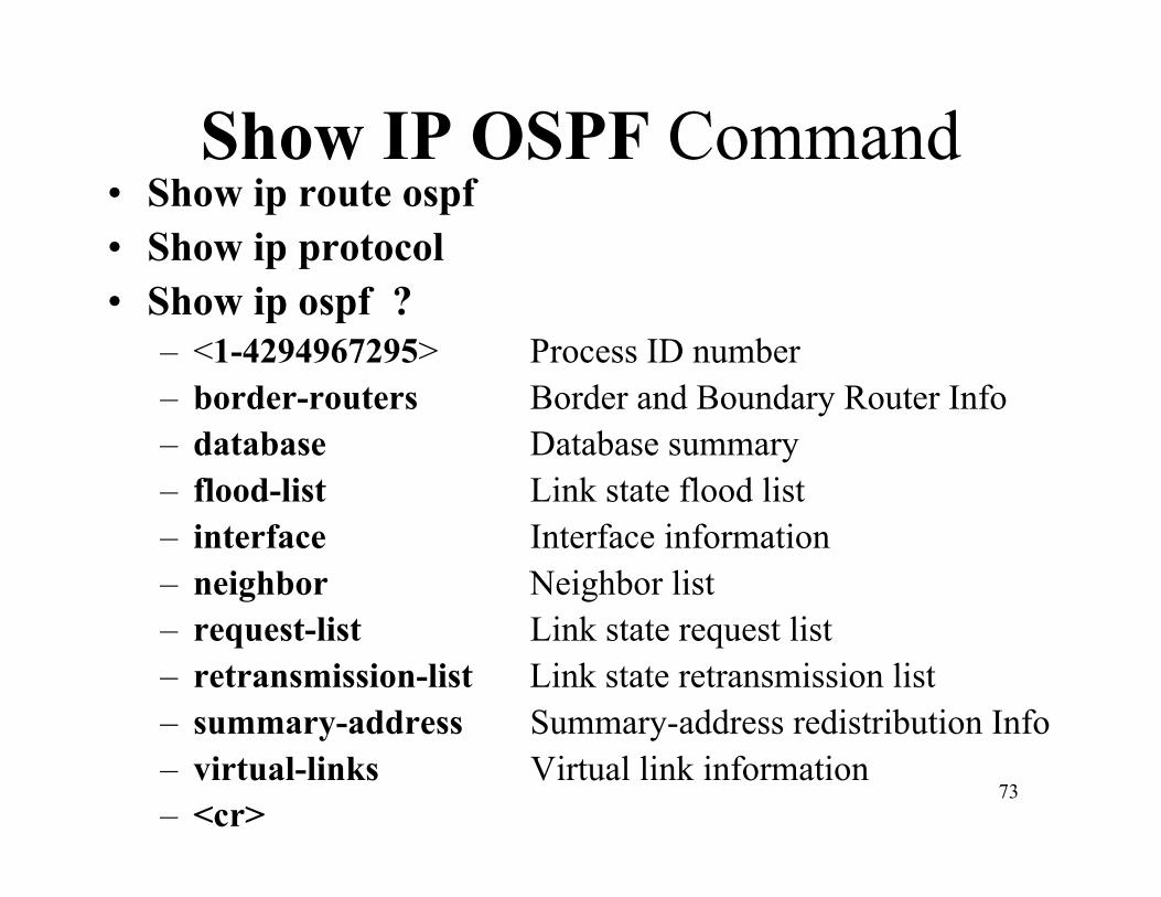
Show IP OSPF Command• Show ip route ospf• Show ip protocol• Show ip ospf ?
– <1-4294967295> Process ID number– border-routers Border and Boundary Router Info– database Database summary– flood-list Link state flood list– interface Interface information– neighbor Neighbor list– request-list Link state request list– retransmission-list Link state retransmission list– summary-address Summary-address redistribution Info– virtual-links Virtual link information– <cr>

74
Show Output
75
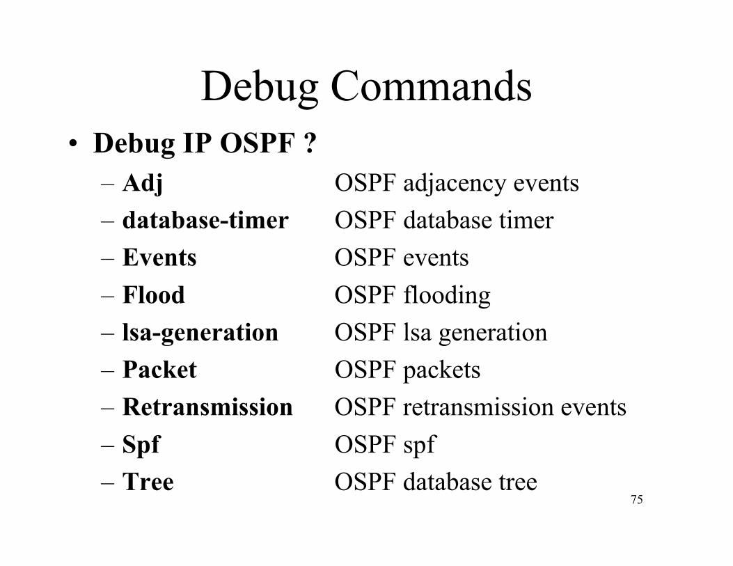
Debug Commands• Debug IP OSPF ?
– Adj OSPF adjacency events– database-timer OSPF database timer– Events OSPF events– Flood OSPF flooding– lsa-generation OSPF lsa generation– Packet OSPF packets– Retransmission OSPF retransmission events– Spf OSPF spf– Tree OSPF database tree
76
Debug Output
LAB 3a:Troubleshooting
Purpose: Run through normal operations andvarious break-and-fix scenarios

Part 4Design

79
OSPF Design
• Backbone• Area X• Traffic Flow• Backup• IGP / EGP Interaction• Miscellaneous
80
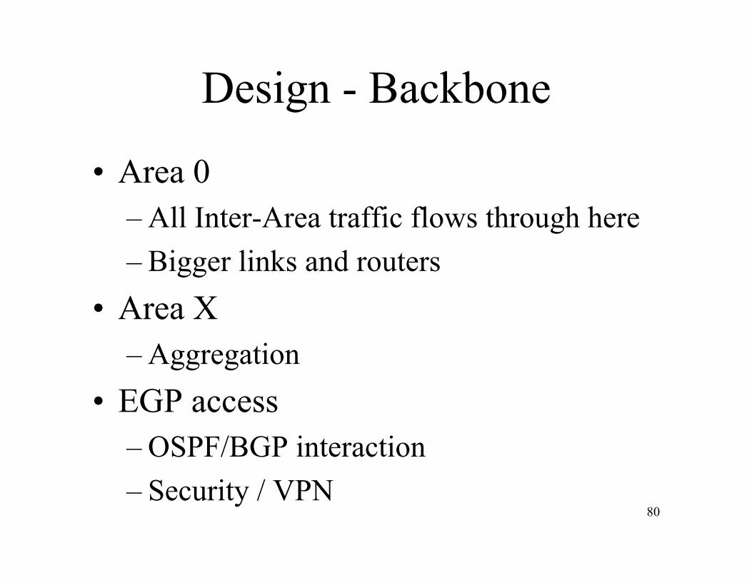
Design - Backbone
• Area 0– All Inter-Area traffic flows through here– Bigger links and routers
• Area X– Aggregation
• EGP access– OSPF/BGP interaction– Security / VPN

81
Design - Area X
• To Stub or not to Stub?• Boundary
– ABR• Virtual Links
– “Healing” Areas• Redistribution
– ASBR• Summarization

82
Example Network - Area 0 / Area X

LAB 4a:Design
Purpose: Initial Area 0 and Area X

84
Design - Traffic Flow• 80/20 - Intra Area / Inter Area• Core, Distribution, Access, Remote Access• Services
– Data– Multicast
• MOSPF (at your own risk)– Voice– Video

85
Design - Backup
• Redundancy• Load-share• On Demand Circuit• Concerns
– Adding on top of existing install

86
Design - IGP / EGP Interaction
• Purpose• Access
– Services• Redistribution
– DON’T DO IT• Security
87
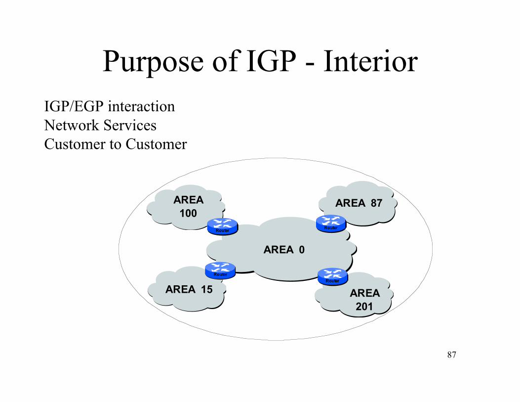
Purpose of IGP - Interior
Router
Router
Router
Router
AREA 0
AREA
201
AREA 87
AREA 15
AREA
100
IGP/EGP interactionNetwork ServicesCustomer to Customer

88
Purpose of IGP - Exterior
Router
Router
Router
Router
AREA 0
AREA
201
AREA 87
AREA 15
AREA
100
Router
Router
Router

89
Design - Miscellaneous
• Security– NAT doesn’t translate routing update– Firewalls can stop routing updates
• Filtering• Virtual Links• Redistribution• Summarization• ABR’s

90
Filtering• Usage
– Affect LSA to Routing Table– Affect LSA distribution
• Interface– Database-filter– Access Control Lists
• OSPF process– Passive Interface– Distribute List (Access Control Lists)

91
Filtering - Usage
Routing Table
DatabaseLSA IN LSA OUT

92
Filtering - Interface
• Database Filterip ospf database-filter
Filter LSA during synchronization and floodingall Filter all LSA
out Outgoing LSA<cr>
93
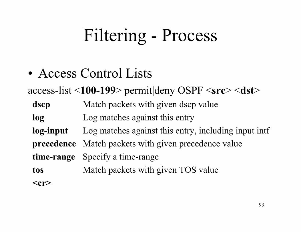
Filtering - Process
• Access Control Listsaccess-list <100-199> permit|deny OSPF <src> <dst> dscp Match packets with given dscp value log Log matches against this entry log-input Log matches against this entry, including input intf precedence Match packets with given precedence value time-range Specify a time-range tos Match packets with given TOS value <cr>
94
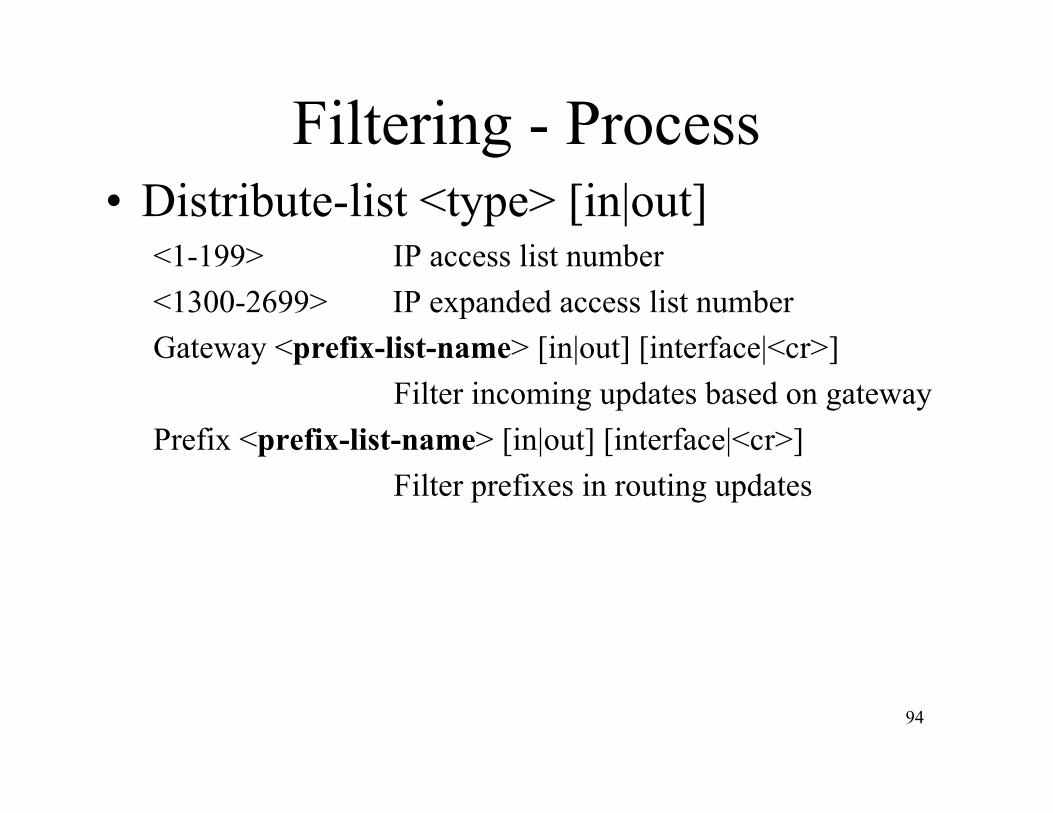
Filtering - Process• Distribute-list <type> [in|out]
<1-199> IP access list number<1300-2699> IP expanded access list numberGateway <prefix-list-name> [in|out] [interface|<cr>]
Filter incoming updates based on gatewayPrefix <prefix-list-name> [in|out] [interface|<cr>]
Filter prefixes in routing updates
95
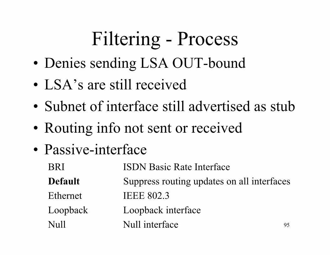
Filtering - Process• Denies sending LSA OUT-bound• LSA’s are still received• Subnet of interface still advertised as stub• Routing info not sent or received• Passive-interface
BRI ISDN Basic Rate InterfaceDefault Suppress routing updates on all interfacesEthernet IEEE 802.3Loopback Loopback interfaceNull Null interface

LAB 4b:Design
Purpose: Understand filtering capabilitiesbetween areas.
97
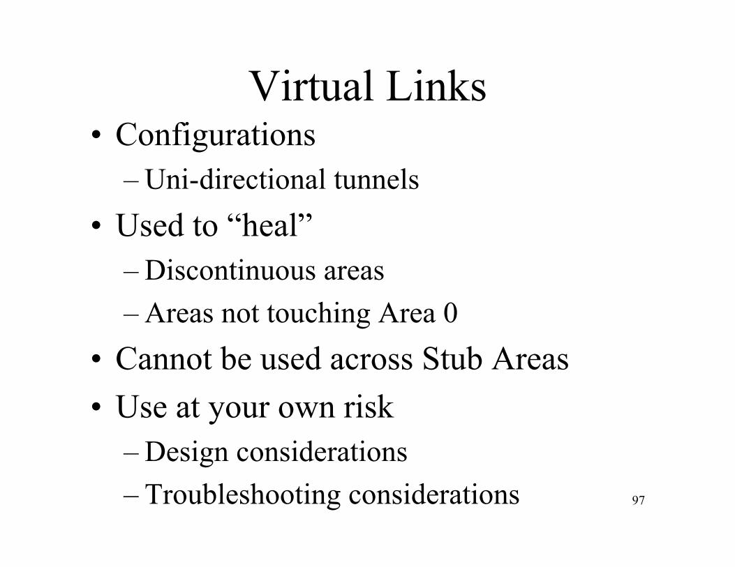
Virtual Links• Configurations
– Uni-directional tunnels• Used to “heal”
– Discontinuous areas– Areas not touching Area 0
• Cannot be used across Stub Areas• Use at your own risk
– Design considerations– Troubleshooting considerations
98
Virtual Links
AREA 0
Router
RouterRouter
AREA
25
AREA
80
AREA
25
99
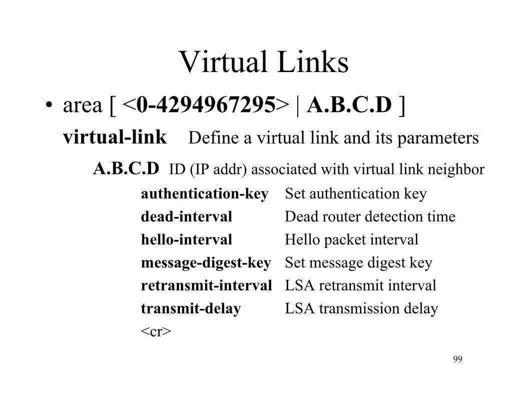
Virtual Links• area [ <0-4294967295> | A.B.C.D ]
virtual-link Define a virtual link and its parametersA.B.C.D ID (IP addr) associated with virtual link neighbor
authentication-key Set authentication keydead-interval Dead router detection timehello-interval Hello packet intervalmessage-digest-key Set message digest keyretransmit-interval LSA retransmit intervaltransmit-delay LSA transmission delay<cr>

LAB 4c:Design
Purpose: Use Virtual Links to “heal” areas.

101
Redistribution• Always tricky no matter the protocol
– NEVER redistribute into BGP– Beware routing loops– Mutual redistribution
• ASBR can generate a default route into OSPF– Use default-information originate [always] …
• Each subnet is redistributed as an external– Use summary-address <address> <mask>
102
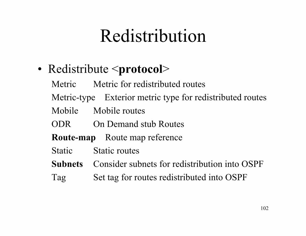
Redistribution
• Redistribute <protocol>Metric Metric for redistributed routesMetric-type Exterior metric type for redistributed routesMobile Mobile routesODR On Demand stub RoutesRoute-map Route map referenceStatic Static routesSubnets Consider subnets for redistribution into OSPFTag Set tag for routes redistributed into OSPF
LAB 4d:Design
Purpose: Understand the effects ofRedistribution and ASBR’s.

104
Summarization
• Summary-address A.B.C.D <mask>not-advertise Do not advertise when translating
OSPF type-7 LSAtag Set tag<cr>

105
Area Boundary Routers
• 1 ABR• 2+ ABR• Type of Area: Intra, Stub, NSSA, TSA
– Default route injected

106
ABR Configuration
Area 0
RouterRouter Router
Area 1
ABR

107
ABR Configuration
Area 0
Router
Area 1
ABR
Router
ABR
RouterRouter

LAB 4e:Design
Purpose: Understand the effects of multipleABR’s connecting Area 0 to Area X.
Part 5References
110
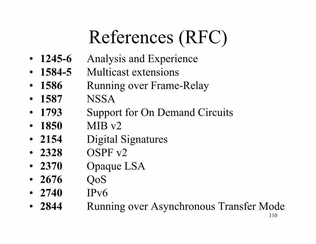
References (RFC)• 1245-6 Analysis and Experience• 1584-5 Multicast extensions• 1586 Running over Frame-Relay• 1587 NSSA• 1793 Support for On Demand Circuits• 1850 MIB v2• 2154 Digital Signatures• 2328 OSPF v2• 2370 Opaque LSA• 2676 QoS• 2740 IPv6• 2844 Running over Asynchronous Transfer Mode

111
References (Web)• www.cisco.com
– /warp/public/104/index.shtml– /univercd/cc/td/doc
• /product/software/ios12/12cgcr/np1_c/1cprt1/1cospf.htm• /cisintwk/ito_doc/ospf.htm• /cisintwk/idg4/nd2003.htm
– /cpress/cc/td/cpress/design/ospf/on0407.htm• www.juniper.net
– /techpubs/software/junos40/swconfig-routing40/html/ospf-overview.html
• www.ietf.org– /html.charters/ospf-charter.html

112
References (Books)
• OSPF Network Design Solutions– Thomas Thomas (cisco Press)
• Interconnections Second Edition– Radia Perlman (Addison Wesley)