open-channel and pipe flow measurement at mohave … · 2017-08-31 · abstract . water for...
TRANSCRIPT

U.S. Department of the Interior Bureau of Reclamation Technical Service Center Hydraulic Investigations and Laboratory Services Group Denver, Colorado
PAP-1049 Emerging Challenges and Opportunities for Irrigation Managers. Albuquerque, New Mexico — April 26-29, 2011 Open-Channel and Pipe Flow Measurement at Mohave Valley Irrigation and Drainage District Using Venturi Technology with Bubbler Sensors By Tom Gill, Mark Niblack, and Alan Jackson
Open-Channel and Pipe Flow Measurement at Mohave Valley Irrigation and Drainage District Using Venturi Technology with Bubbler Sensors
Tom Gill1
Mark Niblack
2
Alan Jackson
3
ABSTRACT
Water for irrigation at Mohave Valley Irrigation and Drainage District (MVIDD) is all pumped from the alluvial aquifer along the Arizona eastern side of the Colorado River. This groundwater pumping is administered as diversion from the Colorado River under a contract between the MVIDD and the US Bureau of Reclamation (Reclamation). Previous efforts to measure pumped flows have been largely unsuccessful due to multiple factors including corrosive agents present in the water, limited head availability and/or limited space availability for proper installation and operation of traditional canal measurement structures. Corrosive agents present in the pumped water have limited the service life for the various flow measurement technologies tried on District pumps. Open channel measurement structures that have been installed at selected sites as part of flow measurement demonstration efforts have met with limited success. Insufficient space between pump discharge and field turnouts or lateral off-takes is a problem for open channel structures at multiple sites. Available freeboard along lined canal sections has proven insufficient for even long-throated flumes, which pose the least head requirements of all critical-flow open channel flow measurement structures. In an effort to address this challenge, Reclamation’s Water Conservation Field Services Program of the Yuma Area Office (YAO) worked with Reclamation’s Hydraulic Investigation and Laboratory Services group (HILS) to devise a plan for measuring flow from each well within MVIDD using technologies that would have an acceptable service life and be cost-effective for an agricultural water system. A combination of venturi-type pipe meters and open channel flumes utilizing the venturi solution for either critical flow or submerged operation – all using bubbler sensors to minimize potential for sensor degradation due to contact with corrosive agents in the water – was devised for MVIDD. Installation of measurement equipment was performed by MVIDD staff in Spring and Summer of 2010. Reclamation began performing calibrations of measurement sites during Fall of 2010. Calibrations are expected to be completed by summer of
1 Hydraulic Engineer, US Bureau of Reclamation, Denver CO 2 Agricultural Engineer, US Bureau of Reclamation (Retired); SCADA Engineer, Yuma County Water Users Assn., Yuma AZ 3 Agricultural Engineer, US Bureau of Reclamation, Yuma AZ

2011. When calibrations are completed, flow data will be telemetered real-time by radio from each site to the MVIDD office.
BACKGROUND
Mohave Valley Irrigation and Drainage District is located in western Arizona along the east side of Colorado River a few miles south of the southern tip of Nevada. All MVIDD waters are pumped from the aquifer fed by the Colorado River. Pumped MVIDD flows are administered as diversions from the Colorado River. By virtue of an agreement dated November 14, 1968 between MVIDD and the US Bureau of Reclamation, MVIDD holds entitlement for use of 41,000 acre feet of Colorado River Water annually. Figure 1 is a site map of the district.
Figure 1. Mohave Valley site map
YAO has worked with MVIDD for over a decade in seeking reliable means of measuring pumped flows. Water quality issues and layout of canal systems have proven to be challenging obstacles for measurement technologies traditionally suitable for agricultural water delivery systems. A high concentration of iron oxide in pumped flows results in deposition of a rust-reddish coating on canal linings and structures that becomes a slimy film when wet and dries to a fine gritty powder. Propeller meters and paddle-type meters that are often utilized for measuring agricultural pipe flow have been shown to have limited life expectancy with this water quality issue. Service life of paddle meters has been on the order of one month while propeller meters typically fail within two seasons. In demonstration tests, affordable acoustic doppler flow meters have performed poorly due to the low suspended solids in the well water.

Issues with canal system layout include limited freeboard with concrete-lined canals, short distances between pump outlets and field turnouts, along with multiple sites where pumped flows entering a canal may be routed in more than one direction to deliver flow to field turnouts. Measuring open channel flows with a standard flume or weir requires a drop in surface elevation at the measurement structure. The required magnitude of this drop varies among standard measurement structures, but must be sufficient to ensure that submergence at a structure does not exceed the modular limit. The additional upstream elevation that would be needed for a critical-flow structure exceeds available canal lining freeboard at numerous sites in the district. Short distances between pump discharge and field turnouts are also problematic for standard open channel measurement structures due to excessive turbulence in flow approaching the structure, and due to potential asymmetric flow paths downstream. Sites where flow may be routed in more than one direction would at a minimum require investment in multiple measurement structures for measuring flow from a single well. It may also be necessary to follow specific operational procedures at multi-directional sites to ensure the quality of measurement data – which may or may not be tasks hired irrigators would carry out reliably. Given the issues encountered with flow measurement technologies commonly used for agricultural water delivery systems, MVIDD has utilized a system of monitoring pump run time as a means of tracking the amount of water pumped. This practice has been reasonably straight forward for wells with electric motors where documentation of power usage is readily available. For wells powered by internal combustion engines, YAO cooperated with MVIDD in examining various tracking systems, including installation of vibration sensors linked to data loggers on selected engine-powered wells. Ultimately, this method proved to be too labor-intensive for MVIDD. In 2008, YAO arranged for Reclamation HILS engineers from the TSC to provide technical assistance in re-visiting options for direct measurement of pumped flows throughout the district. One objective of this effort was to identify a system or systems that would be within the means of MVIDD to operate and maintain. Additionally it was desired (to the extent feasible) to configure a system that streamlines data collection tasks to simplify generation of the required water use reports
PROJECT INITIATION Armed with knowledge of the assortment of flow measurement ideas that have come up against obstacles at MVIDD, YAO suggested that a selected technology (or technologies) be field tested at a selected site (or sites) before proceeding to develop a district-wide implementation plan. Both pipe flow measurement systems as well as open channel measurement systems were

included in feasibility assessments based on recognition that site-specific conditions would likely favor one over the other. In the case of pipe flow measurement, systems with no moving parts were considered. Flow may be determined using a venturi by measuring the difference in pressure heads measured at the full pipe diameter approach section and measured at the reduced cross-section throat section. Venturi meters meet the criteria of a device with no moving parts in contact with the water. Among differential pressure pipe measurement systems, venturi meters are also known for producing comparatively small head loss. HILS proposed using a bubbler pressure sensing system linked to a solenoid valve bank as a means of measuring head differential with a venturi meter. The rationale behind this idea was that air bubbles being emitted from pressure taps might serve to prevent contaminants in the water from plugging tap orifices over time. For open channel measurement YAO opted to look at a long-throated flume configuration. YAO has an extensive history with installing long-throated flumes throughout the service area. Based on long-term operating observations YAO had noted that sediment accumulation behind ramp-type long throated flumes had become a maintenance issue at multiple flume sites. To address this problem some of YAO’s more recent installations had been configured as laterally contracted structures to minimize potential for upstream sediment accumulation.
FIELD TESTS Two sites were selected to test flow measurement systems. Site selection factors included landowner/cooperator interest in participating, suitability of site for assessing the technology, and installation simplicity. Both field test sites selected were on lands owned by the MVIDD Board President. The pipe measurement site was readily accessible from a well-maintained road and was in close proximity to the District office. The open channel site was a similar distance from the District office and was in a location where a single measurement structure could measure all discharge from two wells. Pipe flow field test: The pipe flow measurement field test site (MVIDD well 23) had a 12 in. PVC discharge pipe. The US Department of Agriculture’s Water Conservation Laboratory (Replogle & Wahlin, 1994) conducted a study using venturi meters which were constructed from plastic pipe fittings as cost effective flow measurement devices. Following concepts presented in this paper, a venturi meter for this field test site was constructed by installing a bell reducer near the discharge end of the pipe and reducing to a downstream pipe diameter of 10 in. A rock pile under the pipe allowed limited access to a section of the outlet pipe closer to the well. For this reason the venturi metering section was installed within approximately four feet of the
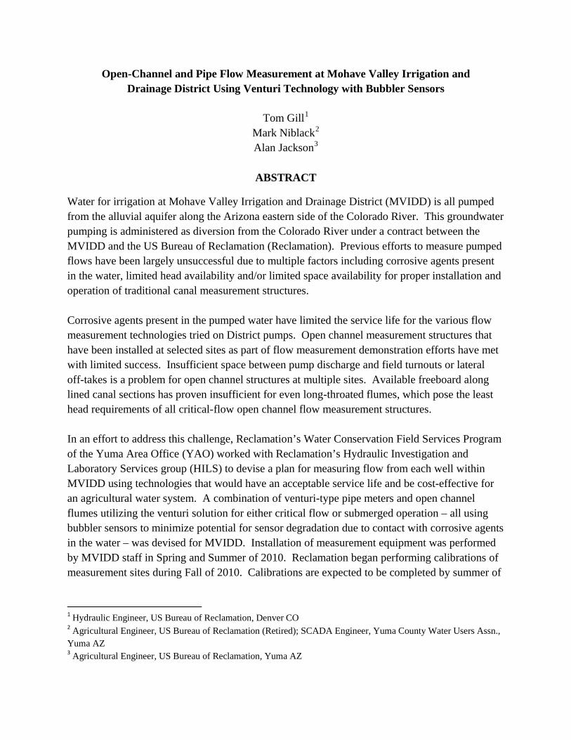
pipe outlet. Initially this meter was installed without an expansion section back to 12 inches for testing purposes. Figure 2 shows the pipe flow measurement field test site.
Figure 2. Pipe flow measurement field test site at MVIDD well 23
The pole-mounted electrical enclosure (Figure 2) houses the bubbler sensor/solenoid valve system, along with the RTU which is programmed to operate the bubbler and valves. Flow measurement data is logged onsite. A base unit at the MVIDD office can be operated to periodically poll data from field sites and write to a data file on the hard drive of a PC linked to the base unit. Bubbler lines are routed from the enclosure through a pipe conduit to tap locations on the pump discharge line. A temporary manometer system was set up to calibrate sensor offsets for each bubbler tap location. Open channel measurement field test: Flow approaching the open channel field test site travels approximately ¼ mile from the nearest well. Flow from a second well travels approximately 3/8 of a mile to the open channel measurement site (MVIDD Wells 18 & 19). A long-throated flume that was installed for the field test was prefabricated at the YAO shops using plastic lumber. The canal reach is concrete lined with a trapezoidal cross section. Canal side slopes are 1.25:1 and canal bottom width is 2.00 ft. The flume itself was designed as a compound contraction with a crest elevation 1.00 ft above the approach section invert and laterally contracted walls with 1:1 side slope. The base of the contracted flume walls meet, leaving a flume with a V-shaped throat section. The field test flume was constructed with a 4 ft long converging section, a 4 ft long throat section and an abrupt expansion. An ultrasonic level sensor was installed in a stilling well to measure canal stage. An RTU unit was programmed to calculate flow based on the electronically-sensed canal stage. The RTU had on-board datalogging capability along with a data display. Figure 3 shows the open channel flow field test site.

Figure 3. Open channel measurement field test at MVIDD wells 18 & 19 measurement site.
YAO Water Conservation Field Services Coordinator Mark Niblack (now retired) is examining the compound contraction long throated flume in Figure 3. The iron oxide deposit seen on the white plastic panels of the flume was accumulated after a single irrigation cycle. As the photo shows the flume caused an increase in upstream water level as evidenced by the comparatively bright colored iron oxide deposits overlaying the darker colored cumulative iron oxide deposits from operations prior to the flume installation. In contrast, recent and cumulative iron oxide deposits on the canal lining below the flume appear to be at the same elevation. Field test findings: Performance of equipment at the pipe flow field test site was encouraging. The site operated from August of 2008 thru March of 2009 without needing service or adjustment. [Farm production at MVIDD is continuous year-round.] A measurement accuracy check was performed by YAO using a Price AA current meter to measure pump discharge in the canal at the time the test site was established. Agreement between the pipe venturi measurement and the current-metered check was within accuracy limits of the current meter method. Based on observations of this field test, the bubbler-sensed venturi meters were selected as the preferred pipe flow measurement technology for the MVIDD flow measurement project. Feedback for field test flume installed at the open channel field test site was less positive. The flume as designed performed well with no concerns regarding submergence. The increased upstream water level created by the flume narrowed the remaining canal freeboard to a margin the land owner was not comfortable with. The limited amount of available freeboard would be a limitation for conventional long-throated flumes at this and other MVIDD sites where open channel flow measurement was being contemplated.

Another field demonstration project that was concurrently being carried out by YAO with HILS assistance at multiple sites near Yuma featured a technology for open channel flow measurement that would be feasible given the constraints present at MVIDD. In this project long throated flumes that frequently or occasionally operated with submergence in excess of modular limits had been equipped with multiple stilling wells to enable measurement of water levels both in the flume approach section and in the throat section. Using the two measured levels, the same concept that was used for calculating flow rate with a pipe venturi meter could be applied to flow through long-throated flumes (“venturi solution” flumes) under normal or excessive submergence.
MVIDD SYSTEM-WIDE FLOW MEASUREMENT PROJECT DESIGN
Factoring in the accumulated institutional knowledge acquired from a decade of working with the district to devise a credible system for measuring and reporting water usage, a design concept for a flow measurement at MVIDD was formulated. In the design process YAO staff considered each pump site individually. Where feasible, installation of a flume would be preferred since flumes would have no direct or perceived impact on the operation of a landowner’s well(s). At sites suitable for a flume and where sufficient upstream freeboard was not in question, a conventional long-throated flume would be installed. Where a flume could effectively measure flow, but where freeboard was in question, a long-throated flume equipped for venturi solution measurement would be installed. At remaining sites a venturi pipe meter would be installed in the discharge pipe from the well. In the YAO design for the twenty-six operating wells in MVIDD, one site was identified where a conventional long-throated flume would be suitable for measuring the output from one well. Four more sites were identified where venturi solution long-throated flumes could be installed. Two of the four venturi solution flume sites were in locations where one flume could measure discharge from two wells. Thus the system design called for discharge from seven of the twenty-six wells to be measured by flumes while venturi meters would be installed in the discharge pipe of the remaining nineteen wells. YAO would assist MVIDD with the installation of flumes. Contractors hired by MVIDD would install the pipe venturi meters. YAO and HILS would assist in performing pressure/level sensor calibrations at all sites and in programming for the RTU units to calculate and record flow measurements. In order to standardize the system and to simplify installation tasks the YAO-developed plan called for use of commercially available “wafer” type venturi meters that are flange mounted and
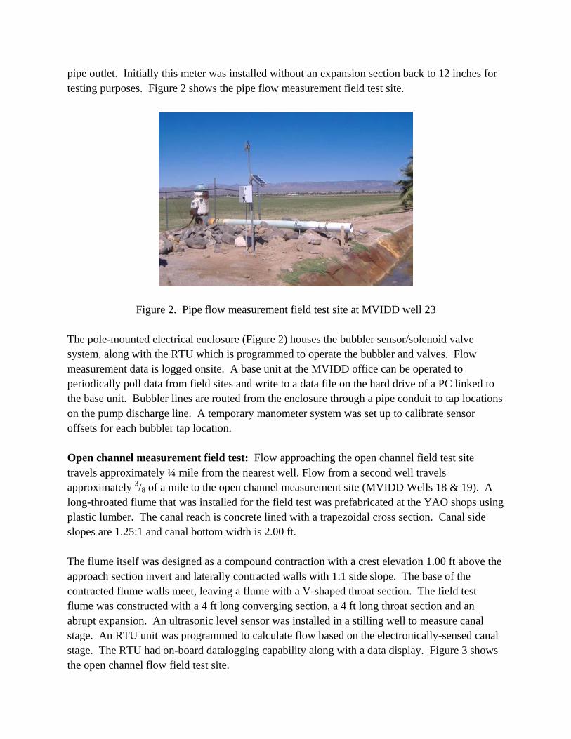
extend in both directions inside the pipe from a single flanged connection. The cost of wafer venturi units would be higher than the cost of materials for venturi meters constructed of pipe fittings similar to the field test venturi at MVIDD well 23 shown in Figure 2. YAO reasoned that opting to use commercially produced venturi meters would diminish quality control concerns associated with venturi systems that would be contractor installed. Given that the MVIDD staff overseeing the meter installations had no experience with venturi technology prior to set up of the MVIDD well 23 field test site, along with the likelihood that available local contractors might have little or no prior experience with venturi meter installation, this could potentially be a significant concern. Figure 4 is a sketch of a wafer venturi.
Figure 4. Sketch of a “wafer” venturi meter
MVIDD FLOW MEASUREMENT SYSTEM IMPLEMENTATION
Flumes at MVIDD were installed with the assistance of YAO and HILS in November, 2009. In the Yuma tests of venturi solution flumes it was determined that for this methodology it is crucial to be able to determine level differential between the flume approach and throat sections with a high degree of precision. A water level measurement configuration utilized in the Yuma demonstration testing included stilling wells for both the flume approach and throat taps. Valves that could be operated from above ground were installed in the pipes connecting each stilling well with the respective canal tap. A pipe linking the stilling wells equipped with a similar valve was also installed. This plumbing system for the stilling wells greatly simplifies sensor calibrations. The stilling wells may readily be isolated from canal flow by closing valves in the tap lines. With stilling wells isolated from the canal, sensor slope calibrations may be performed without impacting canal operations by adding water to, or removing water from, the stilling wells. By opening the valve in the line between wells while at least one of the valves in the canal tap lines is closed, the stilling wells will come to a common level enabling sensor offsets for the respective wells to be accurately calibrated to a common datum. This stilling well configuration was included as part of the venturi solution flume installations in the MVIDD project.

Figure 5 shows the venturi solution long-throated flume that replaced the field test flume shown in Figure 3. The elevation of iron oxide stains seen on the white plastic flume material compared with the elevation of stains on the canal lining on the approach side of the flume (foreground in the photo) show the considerable reduction in upstream level created by this flume compared with the level created by the test flume shown in Figure 3 previously installed at the same location.
Figure 5. Venturi solution long-throated flume at MVIDD 18 & 19
The two stilling wells for measuring water levels in the flume approach and throat sections may be seen at the left of the flume in Figure 5 (white arrows). Standpipes for accessing valves in the pipes connecting the stilling wells to each other and to the canal taps are also shown (black arrows). The venturi solution methodology produces valid flow measurement rates for submergence rates within the flume’s modular limit for critical-flow operation as well as for excessive submergence conditions. The venturi solution flumes installed at MVIDD were designed to create a small increase in upstream canal level to minimize problems associated with limited canal freeboard. The result of limiting the upstream stage increase will be high submergence operating conditions that exceed the flume’s critical-flow modular limits. The implementation of the MVIDD project overlapped a staff transition in the YAO Water Conservation Field Services Program. Shortly after overseeing flume installation in the MVIDD project, Mark Niblack retired from Reclamation in January 2010. The post was temporarily vacant until Alan Jackson joined Reclamation mid March 2010. MVIDD was without a Reclamation Point of Contact for the project during the time that arrangements were being made for contractors to install the pipe venturi meters. After MVIDD had received price quotes for the insertion (wafer) venturi meters, the MVIDD Board of Directors decided to compare the quoted prices with the cost of materials needed to

fabricate pipe fitting venturi meters similar to the field test site shown in Figure 2. The Board ultimately decided in favor of installing custom built pipe fitting venturi meters. MVIDD entered into contract agreements with two local firms for fabrication and installation of the venturi meters. Most of MVIDD wells have steel discharge pipes that run above ground for a short distance between the well and the point of outflow into a canal. Flow from other wells is routed through underground pipelines before emerging above ground and discharging into canals. The well-to-canal conveyance routes differ from a discharge pipe length of about ten feet to over two thousand feet of buried pipe between the well and canal. MVIDD’s decision to opt for pipe-fitting venturi meters, the Reclamation Point of Contact staff transition, the use of multiple installation contractors and the wide variance in well-to-canal conveyance systems all contributed to a high degree of diversity in the resulting MVIDD pipe venturi installations. At well sites with above ground steel discharge lines a pipe fitting venturi was constructed by installing weld-in bell-shape transitions to reduce to a venturi throat then expand back to the original diameter. The transition was one standard pipe size smaller than the original diameter. Wells with buried pipelines were equipped by the contractors with venturi meters in a variety of configurations. Pipe fitting venturi meters were installed in underground sections near the discharge end of the pipeline at four sites. At another site, the pipe fitting venturi was installed above ground in a pipe emerging from the ground at approximately a 45o angle. At two other sites, pipe fitting venturi meters were installed above ground near the respective wells at locations upstream of buried line sections. Figure 6 shows a pipe fitting venturi meter at an MVIDD well with an elevated discharge pipe. The installation shown in Figure 7 is at a well with a discharge pipe at the ground surface.
Figure 6. Pipe venturi at MVIDD 11 Figure 7. Pipe venturi at MVIDD 15
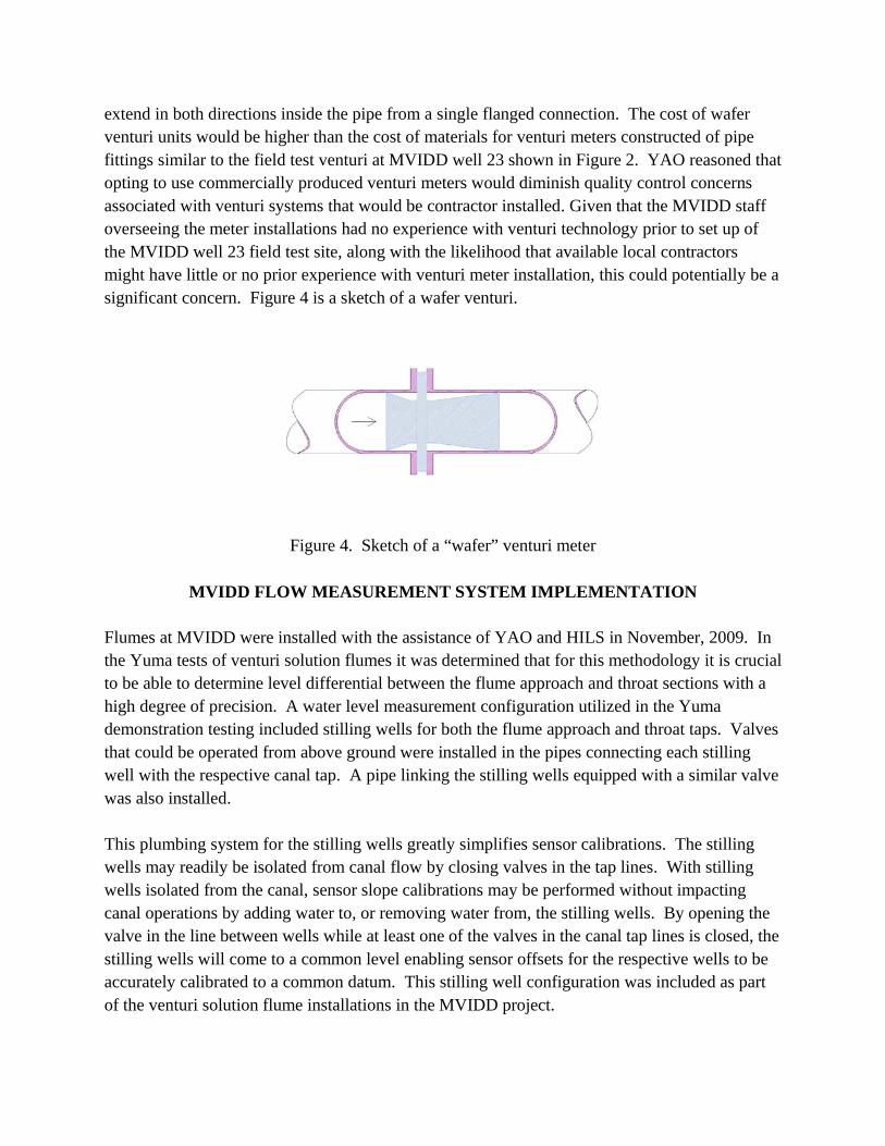
At MVIDD site 29 (shown in Figure 8) a pipe fitting venturi was installed on an underground pipeline. Lines connected to the venturi pressure taps were installed prior to backfill, however venturi meter was buried before sensor offset calibration was performed. In Figure 8 the pipe “daylights” just downstream of the buried venturi. Flow is seen discharging into a vertical “riser” section of concrete pipe.
Figure 8. Underground venturi at MVIDD 29 For the well measurement demonstration field test site shown in Figure 2, a simple manometer system consisting of two lengths of 3/8 inch ID clear vinyl tubing each attached to a venturi pressure tap was assembled in the field to calibrate sensor offsets. Heights of the respective water columns were measured from an arbitrary datum. With this simple manometer apparatus, a small but constant fluctuation in water level was observed in water columns in each manometer. Water column values recorded for the calibration were the average of the observed high and low levels. To calibrate MVIDD’s multiple pipe venturi meters, a double manometer instrument was configured that incorporates stilling wells for each tap. Stilling wells were constructed using 2” PVC pipe. Segments of 3/8 inch ID poly tubing were connected from each venturi tap to a port at the bottom of a stilling well. Clear vinyl sight tubes plumbed to a second port at the bottom of each stilling well extend upward along the outside of the stilling wells. Both stilling wells are secured to a metal bracket such that the sight tubes are positioned approximately 1.5 inches apart. Figure 9 shows the manometer apparatus set up for a venturi sensor offset calibration at the MVIDD 20 well.

Calibrations were performed with wells in operation as seen in Figure 9. At most sites the venturi is installed near the pipe outflow. For these installations tap pressure at the venturi throat is below atmospheric. The bubbler sensors for the MVIDD pipe meters were ordered with absolute pressure sensing transducers specified. A more detailed view of the double manometer is seen in Figure 10. The measured head differential of just over three inches shown in Figure 10 represents the head loss being measured across the venturi at MVIDD well 22.
Figure 9. Double manometer calibration apparatus (arrow) set up at MVIDD well 20
Figure 10. Close-up view of the double manometer apparatus

As a calibration is performed, the bubbler system is initially turned off. Poly tubes are installed linking a manometer stilling well to each venturi tap. The manometer linked to the upstream tap is allowed to fill from the tap. For the low pressure throat tap, water is poured into the top of the stilling well and the well is filled to a level higher than the manometer connection at the throat tap. The throat manometer is then allowed to draw down to a level representing a pressure in equilibrium with the tap. Once both manometers reach static condition, water column levels are read. The base of the metal rail to which both stilling wells are attached serves as a convenient arbitrary datum for measurement of each water column. After water column data has been recorded, the bubbler system is activated, and appropriate tap offset values may be determined for the bubbler sensor. At sites with elevated discharge lines between the well and canal such as MVIDD Well 11 shown in Figure 6, setup for sensor calibration was a straight-forward task. MVIDD Well 15 shown in Figure 7 has the discharge pipe routed along the ground surface. At this and similar sites some minor excavation was necessary for setting up the manometer apparatus due to the fact that the calibration water column surface for the venturi throat tap was below ground level.
CALIBRATION ISSUES Venturi meters for four MVIDD wells, including Well 29 shown in Figure 8 were installed below ground near the location where the pipelines daylight and discharge into a free surface condition. Pipes and fittings used to construct the venturi meters were not well documented by the installing contractors. After installations had been completed, HILS was able to view remnants of some of the pipe materials used to fabricate the venturi meters. Beyond that a verbal description provided by the contractors of pipe materials used at the respective sites was the extent of information available for devising calibration methodologies. At the MVIDD Well 17 location the venturi meter was installed near the well at the upstream end of a ¼ mile long pipeline. The venturi tap pressures at this location – which included the energy needed to account for downstream pipeline transit losses – were problematic for use of the bubbler sensing system. Tap pressures were sufficient to push water up the bubbler tubes through the solenoid valves. Iron oxide deposits left behind as water evaporated between irrigations left valves inoperable during the time interval between system installation and sensor calibration. MVIDD has opted to relocate the meter for this well to a location near the discharge end of the pipeline to eliminate potential for water coming into contact with the bubbler sensing equipment. Multiple issues are present at the MVIDD Well 7 venturi installation seen in Figure 11. As installed none of the upstream, throat or downstream pipe sections have co-linear lines of axis. Outflow at the end of the pipe is approximately half-pipe full. A check of tap pressures was

made by connecting the calibration manometer apparatus. The water column linked to the venturi throat tap was slightly higher than the water column linked to the upstream tap. This would suggest that the throat venturi is positioned to be impacted by dynamic head in the flow. At the time of this writing, MVIDD is re-assessing measurement options at the MVIDD 7 site.
Figure 11. Poorly aligned pipe fitting meter at MVIDD Well 7 Accurate knowledge of the cross sectional flow area at the upstream and throat tap locations is key information need for measuring flow using a venturi meter. As noted above, information provided by the contractors regarding pipe materials utilized for venturi installations was limited. For sites where better information was not available, outside pipe circumferences were measured for each tap location. Using the measured circumferences, pipe OD dimensions were calculated and compared against standard pipe dimension tables to identify the “likely” pipe type and ID dimension. Cross section flow areas were then calculated using the presumed ID dimensions.
SUMMARY An array of issues has impacted the MVIDD flow measurement project with respect to completion schedule along with pipe flow meter quality. At the time of submission of this paper flow measurement systems are measuring discharge from approximately 75% of the MVIDD wells. Most of the remaining sites are expected to be fully operational once meter calibrations are performed. Two of the sites have not yet been calibrated because the pump power units are

awaiting diesel motor repairs. One site is in need of pipeline repairs. Issues with measurement at Wells 7 and 17 are noted above. Flow measurement verifications will be a final task for this project. Verification will be carried out by comparing the flow measurements being generated by the respective MVIDD measurement devices with canal flow measurements obtained using stream gauging techniques. The high degree of diversity in the “as-built” pipe venturi units place added importance on the measurement verifications compared with the level of performance reliability anticipated for the “wafer” venturi units called for in the project design developed by YAO. Despite cited issues that contribute to flow measurement uncertainty, completion of this project will mark a dramatic improvement in MVIDD’s ability to accurately monitor and manage water usage throughout the district. The yet-to-be verified flow data being produced at sites (both flumes and pipe venturi meters) where calibrations have been performed is encouraging. Based on known canal geometry and approximation techniques used to estimate flow velocities, information being produced at all functioning measurement sites appears to be reasonable.
REFERENCES
Replogle, J. A., & Wahlin, B. T. (1994). Venturi Meter Constructions for Plastic Irrigation Pipelines. Applied Engineering in Agriculture , 10 (1), 21-26. Gill, T., & Niblack, M. (2009). Flow Measurement with Long-Throated Flumes Under Uncertain Submergence. Proceedings. Irrigation District Sustainability – Strategies to meet the Challenges. USCID-Reno, Nevada. June 3-6, 2009