opel astra owner's manual · 4 introduction danger, warnings and cautions 9danger text marked...
TRANSCRIPT

OPEL ASTRAOwner's Manual


Introduction .................................... 2In brief ............................................ 6Keys, doors and windows ............ 20Seats, restraints ........................... 41Storage ........................................ 66Instruments and controls ............. 75Lighting ...................................... 118Climate control ........................... 129Driving and operating ................. 139Vehicle care ............................... 195Service and maintenance .......... 240Technical data ........................... 243Customer information ................ 256Index .......................................... 262
Contents

2 Introduction
Introduction

Introduction 3
Vehicle specific dataPlease enter your vehicle's data onthe previous page to keep it easilyaccessible. This information isavailable in the sections "Service andmaintenance" and "Technical data"as well as on the identification plate.
IntroductionYour vehicle is a designedcombination of advanced technology,safety, environmental friendlinessand economy.This Owner's Manual provides youwith all the necessary information toenable you to drive your vehiclesafely and efficiently.Make sure your passengers areaware of the possible risk of accidentand injury which may result fromimproper use of the vehicle.You must always comply with thespecific laws and regulations of thecountry that you are in. These lawsmay differ from the information in thisOwner's Manual.Disregarding the description given inthis manual may affect your warranty.
When this Owner's Manual refers to aworkshop visit, we recommend yourOpel Service Partner.For gas vehicles we recommend anOpel Repairer authorised forservicing gas vehicles.All Opel Service Partners providefirst-class service at reasonableprices. Experienced mechanicstrained by Opel work according tospecific Opel instructions.The customer literature pack shouldalways be kept ready to hand in thevehicle.
Using this manual● This manual describes all options
and features available for thismodel. Certain descriptions,including those for display andmenu functions, may not apply toyour vehicle due to modelvariant, country specifications,special equipment oraccessories.
● The "In brief" section will give youan initial overview.
● The table of contents at thebeginning of this manual andwithin each section shows wherethe information is located.
● The index will enable you tosearch for specific information.
● This Owner's Manual depicts left-hand drive vehicles. Operation issimilar for right-hand drivevehicles.
● The Owner's Manual uses thefactory engine designations. Thecorresponding salesdesignations can be found in thesection "Technical data".
● Directional data, e.g. left or right,or front or back, always relate tothe direction of travel.
● The vehicle display screens maynot support your specificlanguage.
● Display messages and interiorlabelling are written in boldletters.

4 Introduction
Danger, Warnings andCautions
9 Danger
Text marked 9 Danger providesinformation on risk of fatal injury.Disregarding this information mayendanger life.
9 Warning
Text marked 9 Warning providesinformation on risk of accident orinjury. Disregarding thisinformation may lead to injury.
Caution
Text marked Caution providesinformation on possible damage tothe vehicle. Disregarding thisinformation may lead to vehicledamage.
SymbolsPage references are indicated with 3.3 means "see page".Page references and index entriesrefer to the indented headings givenin the section table of content.Chronological order to select menuentries in the vehicle personalisationis indicated with I.We wish you many hours ofpleasurable driving.Adam Opel AG

Introduction 5

6 In brief
In brief
Initial drive information
Vehicle unlocking
Press c to unlock the doors and loadcompartment. Open the doors bypulling the handles.
To open the tailgate, push thetouchpad switch below the brandemblem.Radio remote control 3 21, Centrallocking system 3 24, Electronic keysystem 3 22, Load compartment3 30.

In brief 7
Seat adjustmentLongitudinal adjustment
Pull handle, slide seat, releasehandle. Try to move the seat back andforth to ensure that the seat is lockedin place.Seat position 3 42, Manual seatadjustment 3 43, Power seatadjustment 3 45.
Backrests inclination
Turn handwheel. Do not lean onbackrest when adjusting.Seat position 3 42, Manual seatadjustment 3 43, Power seatadjustment 3 45..
Seat height
Lever pumping motionup : seat higherdown : seat lower
Seat position 3 42, Manual seatadjustment 3 43, Power seatadjustment 3 45.
8 In brief
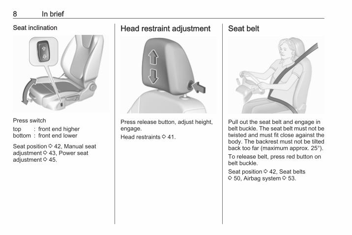
Seat inclination
Press switchtop : front end higherbottom : front end lower
Seat position 3 42, Manual seatadjustment 3 43, Power seatadjustment 3 45.
Head restraint adjustment
Press release button, adjust height,engage.Head restraints 3 41.
Seat belt
Pull out the seat belt and engage inbelt buckle. The seat belt must not betwisted and must fit close against thebody. The backrest must not be tiltedback too far (maximum approx. 25°).To release belt, press red button onbelt buckle.Seat position 3 42, Seat belts3 50, Airbag system 3 53.

In brief 9
Mirror adjustmentInterior mirror
To adjust the mirror, move the mirrorhousing in the desired direction.Manual anti-dazzle interior mirror3 36, Automatic anti-dazzle interiormirror 3 36.
Exterior mirrors
Select the relevant exterior mirror byswitching the rocker control to leftmirror (L) or right mirror (R). Adjustrespective mirror by the four-waycontrol.Convex exterior mirrors 3 34,Electric adjustment 3 34, Foldingexterior mirrors 3 35.Heated exterior mirrors 3 35.
Steering wheel adjustment
Unlock the lever, adjust the steeringwheel, then engage the lever andensure it is fully locked.Do not adjust the steering wheelunless the vehicle is stationary andthe steering wheel lock has beenreleased.Airbag system 3 53, Ignitionpositions 3 140.

10 In brief
Instrument panel overview

In brief 11
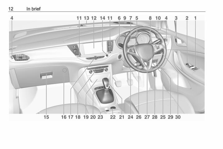
1 Power windows ..................... 372 Exterior mirrors ..................... 343 Central locking system .......... 244 Side air vents ...................... 1375 Cruise control ..................... 163
Speed limiter ....................... 165
Forward collision alert ......... 1676 Turn and lane-change
signals, headlight flash,low/high beam, high beamassist ................................... 124
Exit lighting ......................... 127
Parking lights ...................... 125
Buttons for DriverInformation Centre ................ 98
7 Instruments .......................... 88
Driver Information Centre ...... 988 Buttons for Driver
Information Centre ................ 989 Forward collision alert
indicator ............................. 16710 Windscreen wiper and
washer, rear wiper andwasher ................................. 77
11 Centre air vents .................. 13712 Info-Display ........................ 10313 Anti-theft alarm system
status LED ........................... 3114 Hazard warning flashers .... 12315 Glovebox .............................. 6616 CD player17 Controls for Info-Display
operation ............................. 10318 Climate control system ........ 13019 Fuse box ............................ 214
Power connector .................. 8320 Sport mode ........................ 163
Traction Control system ..... 160
Electronic Stability Control . 161
Parking assist/Advancedparking assist ..................... 171
Lane keep assist ................ 186
Eco button for stop-startsystem ................................. 145
21 Manual transmission .......... 154
Automatic transmission ...... 151
Manual transmissionautomated ........................... 155
22 Power outlet .......................... 8223 Parking brake ...................... 15824 Power button ....................... 14125 Ignition switch ..................... 14026 Steering wheel adjustment . . 7627 Horn ..................................... 7728 Bonnet release lever .......... 19729 Storage compartment ........... 6730 Light switch ........................ 118
Headlight rangeadjustment ......................... 119
Front/rear fog lights ............ 124
Instrument illumination ....... 126
12 In brief

In brief 13
Exterior lighting
AUTO : automatic light controlswitches automaticallybetween daytime runninglight and headlight
8 : sidelights9 : headlights
Automatic light control 3 119.
Fog lightsPress buttons in light switch> : front fog lightsr : rear fog light
Headlight flash, high beam andlow beam
headlight flash : pull leverhigh beam : push leverlow beam : push or pull lever
High beam 3 119, Headlight flash3 119, LED headlights 3 120, Highbeam assist 3 120.
Turn and lane-change signals
lever up : right turn signallever down : left turn signal
Turn and lane-change signals3 124, Parking lights 3 125.

14 In brief
Hazard warning flashers
Operated by pressing ¨.Hazard warning flashers 3 123.
Horn
Press j.
Washer and wiper systemsWindscreen wiper
HI : fastLO : slowINT : interval wiping
orautomatic wiping with rainsensor
OFF : off
For single wipe when the wiper is off,press lever down to position 1x.Windscreen wiper 3 77.

In brief 15
Windscreen washer
Pull lever.Windscreen washer system 3 77,Washer fluid 3 200, Wiper bladereplacement 3 203.
Rear window wiper
Turn outer cap to activate the rearwindow wiper:ON : continuous operationINT : intermittent operationOFF : off
Rear window washer
Push lever.Washer fluid is sprayed on the rearwindow and the wiper wipes a fewtimes.Rear window wiper/washer 3 79.

16 In brief
Climate controlHeated rear window
The heating is operated by pressingÜ.Heated rear window 3 39.
Heated exterior mirrorsPressing Ü also activates the heatedexterior mirrors.Heated exterior mirrors 3 35.
Demisting and defrosting thewindows
● Press V: the air distribution isdirected towards the windscreen.
● Set fan speed to highest level.● Set temperature control to
warmest level.● Switch on heated rear window Ü.● Open side air vents as required
and direct them towards the doorwindows.
Heating and ventilation system3 129, air conditioning system3 130, electronic climate controlsystem 3 132.
TransmissionManual transmission
Reverse: with the vehicle stationary,depress clutch pedal and press therelease button on the selector leverand engage the gear.Manual transmission 3 154.

In brief 17
Automatic transmission
P : park positionR : reverseN : neutral modeD : automatic modeM : manual mode< : upshift] : downshift
The selector lever can only be movedout of P when the ignition is on andthe brake pedal is applied. To engageP or R, press the release button.Automatic transmission 3 151.
Manual transmission automated
N : neutral positionD : automatic modeM : manual mode< : upshift] : downshiftR : reverse
Engage reverse only whenvehicle is stationary.
Manual transmission automated3 155.
Starting offCheck before starting off● Tyre pressure and condition
3 219, 3 254.● Engine oil level and fluid levels
3 198.● All windows, mirrors, exterior
lighting and number plates arefree from dirt, snow and ice andare operational.
● Proper position of mirrors, seats,and seat belts 3 34, 3 42,3 51.
● Brake function at low speed,particularly if the brakes are wet.

18 In brief
Starting the engine
● Ignition switch: turn key toposition 2.Power button: pressEngine Start/Stop for a fewseconds until green LEDilluminates.
● Move the steering wheel slightlyto release the steering wheellock.
● Manual transmission: operateclutch and brake pedal.Manual transmission automated:operate brake pedal.
Automatic transmission: operatebrake pedal and move selectorlever to P or N.
● Do not operate accelerator pedal.● Diesel engines: wait until control
indicator ! for preheatingextinguishes.
● Ignition switch: turn key toposition 3 and release.
Power button: pressEngine Start/Stop and release.
Starting the engine 3 143.
Stop-start system
If the vehicle is at a low speed or at astandstill and certain conditions arefulfilled, an Autostop is activated.An Autostop is indicated by theneedle at the AUTOSTOP position inthe tachometer.A restart is indicated by the needle atthe idle speed position in thetachometer.Stop-start system 3 145.

In brief 19
Parking
9 Warning
● Do not park the vehicle on aneasily ignitable surface. Thehigh temperature of theexhaust system could ignite thesurface.
● Always apply the parkingbrake. Activate the manualparking brake without pressingthe release button. Apply asfirmly as possible on a downhillslope or uphill slope. Depressbrake pedal at the same time toreduce operating force.For vehicles with electricparking brake, pull switch m fora minimum of one second untilcontrol indicator m illuminatesconstantly and electric parkingbrake is applied 3 94.
● Switch off the engine.● If the vehicle is on a level
surface or uphill slope, engagefirst gear or set the selector
lever to position P beforeremoving the ignition key orswitching off ignition onvehicles with power button. Onan uphill slope, turn the frontwheels away from the kerb.If the vehicle is on a downhillslope, engage reverse gear orset the selector lever to positionP before removing the ignitionkey or switching off ignition onvehicles with power button.Turn the front wheels towardsthe kerb.
● Close the windows and thesunroof.
● Remove the ignition key fromthe ignition switch or switch offignition on vehicles with powerbutton. Turn the steering wheeluntil the steering wheel lock isfelt to engage.For vehicles with automatictransmission, the key can onlybe removed when the selectorlever is in position P.
For vehicles with manualtransmission automated, thekey can only be removed fromthe ignition switch when theparking brake is applied.
● Lock the vehicle with e on theradio remote control.Activate the anti-theft alarmsystem 3 31.
● The engine cooling fans may runafter the engine has beenswitched off 3 197.
Caution
After running at high enginespeeds or with high engine loads,operate the engine briefly at a lowload or run in neutral forapprox. 30 seconds beforeswitching off, in order to protectthe turbocharger.
Keys, locks 3 20, Laying-up thevehicle for a long period of time3 196.

20 Keys, doors and windows
Keys, doors andwindows
Keys, locks ................................... 20Keys .......................................... 20Radio remote control ................. 21Electronic key system ................ 22Memorised settings ................... 24Central locking system .............. 24Automatic locking ...................... 28Child locks ................................. 29
Doors ........................................... 30Load compartment .................... 30
Vehicle security ............................ 31Anti-theft locking system ........... 31Anti-theft alarm system .............. 31Immobiliser ................................ 34
Exterior mirrors ............................ 34Convex shape ........................... 34Electric adjustment .................... 34Folding mirrors .......................... 35Heated mirrors ........................... 35
Interior mirrors ............................. 36Manual anti-dazzle .................... 36Automatic anti-dazzle ................ 36
Windows ...................................... 36Windscreen ............................... 36Manual windows ........................ 37Power windows ......................... 37Heated rear window .................. 39Sun visors .................................. 39
Roof ............................................. 39Sunroof ...................................... 39
Keys, locksKeys
Caution
Do not attach heavy or bulky itemsto the ignition key.
Replacement keysThe key number is specified on adetachable tag.The key number must be quotedwhen ordering replacement keys as itis a component of the immobilisersystem.Locks 3 237, Radio remote control3 21, Electronic key 3 22, Centrallocking 3 24, Starting the engine3 143.The code number of the adapter forthe locking wheel nuts is specified ona card. It must be quoted whenordering a replacement adapter.Wheel changing 3 228.

Keys, doors and windows 21
Key with foldaway key section
Press button to extend. To fold thekey, first press the button.
Radio remote control
Enables operation of the followingfunctions via the use of the remotecontrol buttons:● central locking system 3 24● anti-theft locking system 3 31● anti-theft alarm system 3 31● power windows 3 37● sunroof 3 39
The remote control has a range of upto 100 metres, but may also be muchless due to external influences. Thehazard warning flashers confirmoperation.
Handle with care, protect frommoisture and high temperatures andavoid unnecessary operation.
Replacing battery in radio remotecontrolReplace the battery as soon as therange reduces.
Batteries do not belong in householdwaste. They must be disposed of atan appropriate recycling collectionpoint.

22 Keys, doors and windows
1. Insert flat screwdriver into the slotand separate the back cover fromthe remote control by slightlyturning the screwdriver.
2. Remove and replace battery. UseCR 2032 or equivalent battery.Pay attention to the installationposition.
3. Insert the back cover in the areaof the key blade, fold down andclose.
Radio remote controlsynchronisationAfter replacing the battery, unlock thedoor with the key in the driver's doorlock. The radio remote control will besynchronised when you switch on theignition.
FaultIf the central locking system cannotbe operated with the radio remotecontrol, the cause may be one of thefollowing:● Fault in radio remote control.● The range is exceeded.● The battery voltage is too low.● Frequent, repeated operation of
the radio remote control while notin range, which will require re-synchronisation.
● Overload of the central lockingsystem by operating at frequentintervals, the power supply isinterrupted for a short time.
● Interference from higher-powerradio waves from other sources.
Manual unlocking 3 24.
Electronic key system
Enables a keyless operation of thefollowing functions:● central locking system 3 24● tailgate 3 30● ignition switching on and starting
the engine 3 143The electronic key simply needs to beon the driver's person.Additionally, the electronic keyincludes the functionality of the radioremote control 3 21.Handle with care, protect frommoisture and high temperatures andavoid unnecessary operation.

Keys, doors and windows 23
NoteDo not put the electronic key in theload compartment or in front of theInfo-Display.
Replacing battery in electronickeyReplace the battery as soon as thesystem no longer operates properlyor the range is reduced. The need forbattery replacement is indicated by amessage in the Driver InformationCentre 3 105.
Batteries do not belong in householdwaste. They must be disposed of atan appropriate recycling collectionpoint.
To replace:
1. Press button at the back of theelectronic key unit and extract thekey blade from the housing.
2. Insert flat screwdriver or the keyblade at the side of the housingand separate the back cover fromthe electronic unit by turning thescrewdriver or key blade.
3. Remove and replace battery. UseCR 2032 or equivalent battery.Pay attention to the installationposition.
4. Install back cover of the electronicunit and insert key element.
Batteries do not belong in householdwaste. They must be disposed of atan appropriate recycling collectionpoint.
Electronic key synchronisationThe electronic key synchronises itselfautomatically during every startingprocedure.

24 Keys, doors and windows
FaultIf the central locking cannot beoperated or the engine cannot bestarted, the cause may be one of thefollowing:● Fault in electronic key.● Electronic key is out of reception
range.● The battery voltage is too low.● Overload of the central locking
system by operating at frequentintervals, the power supply isinterrupted for a short time.
● Interference from higher-powerradio waves from other sources.
To rectify the cause of the fault,change the position of the electronickey.Manual unlocking 3 24.
Memorised settingsWhenever the ignition is switched off,the following settings areautomatically memorised by theremote control unit or the electronickey:
● automatic climate control● lighting● Infotainment system● central locking system● Sport mode settings● comfort settings
The saved settings are automaticallyused the next time the ignition isswitched on with the memorised keyof the remote control unit 3 140 orelectronic key 3 22.A precondition is that Personalisationby Driver is activated in the personalsettings of the Info-Display. This mustbe set for each remote control unit orelectronic key which is used.The settings of the driver's seat arealso memorised independent of thememory positions 3 45.The power seat automatically movesinto the saved position whenunlocking and opening the driver'sdoor with the memorised remotecontrol or electronic key and AutoMemory Recall in the Info-Display isactivated.Vehicle personalisation 3 107.
Central locking systemUnlocks and locks doors, loadcompartment and fuel filler flap.A pull on an interior door handleunlocks the respective door. Pullingthe handle once more opens the door.NoteIn the event of an accident in whichairbags or belt pretensioners aredeployed, the vehicle isautomatically unlocked.NoteA short time after unlocking with theremote control the doors are lockedautomatically if no door has beenopened. A precondition is that thesetting is activated in the vehiclepersonalisation 3 107.

Keys, doors and windows 25
Remote control operation
Unlocking
Press c.Unlocking mode can be set in thevehicle personalisation menu in theInfo-Display. Two settings areselectable:● All doors, load compartment and
fuel filler flap will be unlocked bypressing c once.
● Only the driver's door, loadcompartment and fuel filler flapwill be unlocked by pressing conce. To unlock all doors, pressc twice.
Select the relevant setting in Settings,I Vehicle in the Info-Display.Info-Display 3 103.Vehicle personalisation 3 107.The setting can be saved for theremote control being used.Memorised settings 3 24.Unlocking and opening the tailgate3 30.
LockingClose doors, load compartment andfuel filler flap.
Press e.
If the driver's door is not closedproperly, the central locking systemwill not work.
ConfirmationOperation of the central lockingsystem is confirmed by the hazardwarning flashers. A precondition isthat the setting is activated in thevehicle personalisation 3 107.
Electronic key system operation
The electronic key must be outsidethe vehicle, within a range of approx.one metre of the relevant door side.

26 Keys, doors and windows
Unlocking
Press the button on the respectiveexterior door handle and pull thehandle.Unlocking mode can be set in thevehicle personalisation menu in theInfo-Display. Two settings areselectable:● All doors, load compartment and
fuel filler flap will be unlocked bypressing the button on anyexterior handle once.
● Only the driver's door, loadcompartment and fuel filler flapwill be unlocked by pressing the
button on the driver`s doorexterior handle once. To unlockall doors, press button twice.
The setting can be changed in themenu Settings in the Info-Display.Vehicle personalisation 3 107.
Locking
Press the button on any exterior doorhandle.All doors, load compartment and fuelfiller flap will be locked.
The system locks if any of thefollowing occurs:● It has been more than
five seconds since unlocking.● The button on an exterior handle
has been pressed twice withinfive seconds to unlock thevehicle.
● Any door has been opened andall doors are now closed.
If the driver's door is not closedproperly, the electronic key remains inthe vehicle or the ignition is not off,locking will not be permitted and awarning chime sounds three times.If there have been two or moreelectronic keys in the vehicle and theignition was on once, the doors will belocked even if just one electronic keyis taken out of the vehicle.
Unlocking and opening the tailgateThe tailgate can be unlocked andopened by pushing the touchpadswitch under the brand emblem whenthe electronic key is in range. Thedoors remain locked.
Keys, doors and windows 27
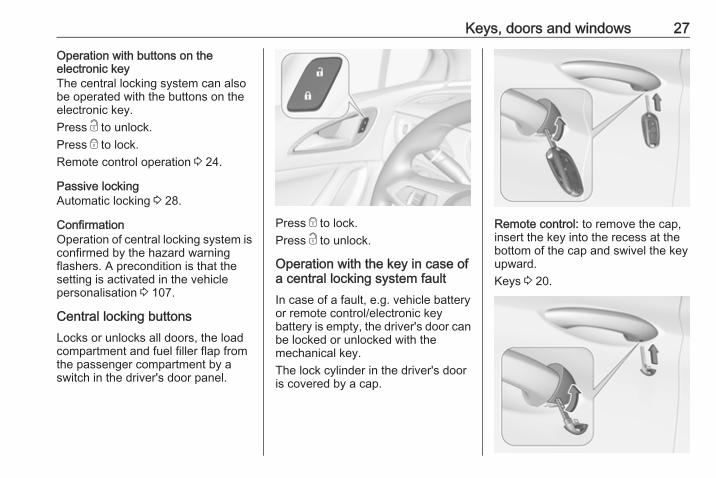
Operation with buttons on theelectronic keyThe central locking system can alsobe operated with the buttons on theelectronic key.Press c to unlock.Press e to lock.Remote control operation 3 24.
Passive lockingAutomatic locking 3 28.
ConfirmationOperation of central locking system isconfirmed by the hazard warningflashers. A precondition is that thesetting is activated in the vehiclepersonalisation 3 107.
Central locking buttonsLocks or unlocks all doors, the loadcompartment and fuel filler flap fromthe passenger compartment by aswitch in the driver's door panel.
Press e to lock.Press c to unlock.
Operation with the key in case ofa central locking system faultIn case of a fault, e.g. vehicle batteryor remote control/electronic keybattery is empty, the driver's door canbe locked or unlocked with themechanical key.The lock cylinder in the driver's dooris covered by a cap.
Remote control: to remove the cap,insert the key into the recess at thebottom of the cap and swivel the keyupward.Keys 3 20.

28 Keys, doors and windows
Electronic key: to remove the cap,press button at the back and extractthe key blade from the housing. Insertthe key into the recess at the bottomof the cap and swivel the key upward.Electronic key system 3 22.
Manual unlocking
Manually unlock the driver's door byinserting and turning the key in thelock cylinder.The other doors can be opened bypulling the interior handle twice or bypressing c in the driver's door panel.The load compartment and fuel fillerflap will possibly not be unlocked.
By switching on the ignition, the anti-theft locking system is deactivated.
Manual locking
Push inside locking knob of all doorsexcept driver's door or press e in thedriver's door panel. Then close thedriver's door and lock it from theoutside by turning the key in the lockcylinder. The fuel filler flap andtailgate are possibly not locked.
After locking, cover the lock cylinderwith the cap: insert the cap with thelower side in the recesses, swivel andpush the cap until it engages at theupper side.
Automatic lockingAutomatic locking after driving offThis security feature can beconfigured to automatically lock alldoors, load compartment and fuelfiller flap after driving off andexceeding a certain speed.

Keys, doors and windows 29
When at a standstill after driving, thevehicle will be unlocked automaticallyas soon as the key is removed fromthe ignition switch, or with electronickey system when the ignition isswitched off.Activation or deactivation ofautomatic locking can be set in themenu Settings, I Vehicle in the Info-Display.Info-Display 3 103.Vehicle personalisation 3 107.The setting can be saved for theremote control or electronic key beingused 3 24.
Automatic relock after unlockingThis feature can be configured toautomatically lock all doors, loadcompartment and fuel filler flap ashort time after unlocking with theremote control or electronic key,provided no door has been opened.Activation or deactivation ofautomatic relock can be set in themenu Settings, I Vehicle in the Info-Display.Info-Display 3 103.
Vehicle personalisation 3 107.The setting can be saved for theremote control or electronic key beingused 3 24.
Passive lockingOn vehicles with electronic keysystem, this feature locks the vehicleautomatically after several seconds ifan electronic key has beenrecognised previously inside thevehicle, all doors have then beenclosed and the electronic key doesnot remain in the interior.If the electronic key remains in thevehicle or the ignition is not off,passive locking will not be permitted.If there have been two or moreelectronic keys in the vehicle and theignition was on once, the featurelocks the vehicle if just one electronickey is taken out of the vehicle.Passive locking can be disabled bypressing c for a few seconds whileone door is open. It remains disableduntil e is pressed or the ignition isswitched on.
Activation or deactivation of passivelocking can be set in the menuSettings, I Vehicle in the Info-Display.Info-Display 3 103.Vehicle personalisation 3 107.The setting can be saved for theremote control or electronic key beingused 3 24.
Child locks

30 Keys, doors and windows
9 Warning
Use the child locks wheneverchildren are occupying the rearseats.
Move the pin in the rear door to thefront. The door cannot be openedfrom the inside.To deactivate, move the pin to therear position.
DoorsLoad compartmentTailgate
Opening
After unlocking, push the touchpadswitch under the brand emblem andopen the tailgate.Central locking system 3 24.
Closing
Use one of the interior handles.Do not push the touchpad switchwhilst closing as this will unlock thetailgate again.Central locking system 3 24.
General hints for operatingtailgate
9 Danger
Do not drive with the tailgate openor ajar, e.g. when transportingbulky objects, since toxic exhaust

Keys, doors and windows 31
gases, which cannot be seen orsmelled, could enter the vehicle.This can cause unconsciousnessand even death.
Caution
Before opening the tailgate, checkoverhead obstructions, e.g. agarage door, to avoid damage tothe tailgate. Always check themoving area above and behind thetailgate.
NoteThe installation of certain heavyaccessories onto the tailgate mayaffect its ability to remain open.
Vehicle securityAnti-theft locking system
9 Warning
Do not use the system if there arepeople in the vehicle! The doorscannot be unlocked from theinside.
The system deadlocks all the doors.All doors must be closed otherwisethe system cannot be activated.If the ignition was on, the driver's doormust be opened and closed once sothat the vehicle can be secured.Unlocking the vehicle disables themechanical anti-theft locking system.This is not possible with the centrallocking button.
Activating
Press e on the radio remote controltwice within five seconds.
Anti-theft alarm systemThe anti-theft alarm system iscombined with the anti-theft lockingsystem.It monitors:● doors, tailgate, bonnet● passenger compartment
including adjoining loadcompartment

32 Keys, doors and windows
● vehicle inclination, e.g. if it israised
● ignition
ActivationAll doors must be closed and theelectronic key of the electronic keysystem must not remain in thevehicle. Otherwise the system cannotbe activated.● Radio remote control: self-
activated 30 seconds afterlocking the vehicle by pressing eonce.
● Electronic key system: self-activated 30 seconds afterlocking the vehicle by pressingthe button on any exterior doorhandle.
● Radio remote control orelectronic key: directly bypressing e twice withinfive seconds.
● Electronic key system withpassive locking enabled: brieflyactivated after passive lockingoccurs.
NoteChanges to the vehicle interior suchas the use of seat covers, and openwindows or sunroof, could impair thefunction of passenger compartmentmonitoring.
Activation without monitoring ofpassenger compartment andvehicle inclination
Switch off the monitoring ofpassenger compartment and vehicleinclination when animals are beingleft in the vehicle, because of highvolume ultrasonic signals ormovements triggering the alarm. Alsoswitch off when the vehicle is on aferry or train.1. Close tailgate, bonnet, windows
and sunroof.2. Press o. LED in the button o
illuminates for a maximum often minutes.

Keys, doors and windows 33
3. Close doors.4. Activate the anti-theft alarm
system.Status message is displayed in theDriver Information Centre.
Status LED
Status LED is integrated in the sensoron top of the instrument panel.Status during the first 30 seconds ofanti-theft alarm system activation:LED illuminates : test, arming delayLED flashesquickly
: doors, tailgate orbonnet notcompletely closed,or system fault
Status after system is armed:LED flashesslowly
: system is armed
Seek the assistance of a workshop inthe event of faults.
DeactivationRadio remote control: Unlocking thevehicle by pressing c deactivates theanti-theft alarm system.
Electronic key system: Unlocking thevehicle by pressing the button on anyexterior door handle deactivates theanti-theft alarm system.
The electronic key must be outsidethe vehicle, within a range of approx.one metre of the relevant door side.The system is not deactivated byunlocking the driver's door with thekey or with the central locking buttonin the passenger compartment.
AlarmWhen triggered, the alarm hornsounds and the hazard warning lightsflash simultaneously. The numberand duration of alarm signals arestipulated by legislation.The anti-theft alarm system can bedeactivated by pressing c, bypressing the switch on the doorhandle with electronic key system orswitching on the ignition.A triggered alarm, which has not beeninterrupted by the driver, will beindicated by the hazard warninglights. They will flash quickly threetimes the next time the vehicle isunlocked with the radio remotecontrol. Additionally a warningmessage is displayed in the DriverInformation Centre after switching onthe ignition.

34 Keys, doors and windows
Vehicle messages 3 105.
ImmobiliserThe system is part of the ignitionswitch and checks whether thevehicle is allowed to be started withthe key being used.The immobiliser is activatedautomatically after the key has beenremoved from the ignition switch.If the control indicator d flashes whenthe ignition is on, there is a fault in thesystem; the engine cannot be started.Switch off the ignition and repeat thestart attempt.If the control indicator d continuesflashing, attempt to start the engineusing the spare key and seek theassistance of a workshop.NoteRadio Frequency Identification(RFID) tags may cause interferencewith the key. Do not have it placednear the key when starting thevehicle.
NoteThe immobiliser does not lock thedoors. You should always lock thevehicle after leaving it and switch onthe anti-theft alarm system 3 24,3 31.
Control indicator d 3 97.
Exterior mirrorsConvex shapeThe convex exterior mirror on thedriver's side contains an asphericalarea and reduces blind spots. Theshape of the mirror makes objectsappear smaller, which will affect theability to estimate distances.Side blind spot alert 3 179.
Electric adjustment

Keys, doors and windows 35
Select the relevant exterior mirror byswitching the control to left (L) or right(R). Then swivel the control to adjustthe mirror.In position o no mirror is selected.
Folding mirrors
For pedestrian safety, the exteriormirrors will swing out of their normalmounting position if they are struckwith sufficient force. Reposition themirror by applying slight pressure tothe mirror housing.
Electric folding
Switch control to o, then push thecontrol c down. Both exterior mirrorswill fold.Push the control down again - bothexterior mirrors return to their originalposition.If an electrically folded mirror ismanually extended, pressing downthe control will only electrically extendthe other mirror.
Heated mirrors
Operated by pressing Ü.Heating works with the enginerunning and is switched offautomatically after a short time.

36 Keys, doors and windows
Interior mirrorsManual anti-dazzle
To reduce dazzle, adjust the lever onthe underside of the mirror housing.
Automatic anti-dazzle
Dazzle from following vehicles atnight is automatically reduced.
WindowsWindscreenWindscreen stickersDo not attach stickers such as tollroad stickers or similar on thewindscreen in the area of the interiormirror. Otherwise the detection zoneof the sensor and the view area of thecamera in the mirror housing could berestricted.
Windscreen replacement
Caution
If the vehicle has a front-lookingcamera sensor for the driverassistance systems, it is veryimportant that any windscreenreplacement is performedaccurately according to Opelspecifications. Otherwise, thesesystems may not work properlyand there is a risk of unexpectedbehaviour and/or messages fromthese systems.

Keys, doors and windows 37
Manual windowsThe door windows can be opened orclosed with the window cranks.
Power windows
9 Warning
Take care when operating thepower windows. Risk of injury,particularly to children.If there are children on the rearseats, switch on the child safetysystem for the power windows.Keep a close watch on thewindows when closing them.Ensure that nothing becomestrapped in them as they move.
Switch on ignition to operate powerwindows. Retained power off 3 142.
Operate the switch for the respectivewindow by pushing to open or pullingto close.Pushing or pulling gently to the firstdetent: window moves up or down aslong as the switch is operated.Pushing or pulling firmly to the seconddetent then releasing: window movesup or down automatically with safetyfunction enabled. To stop movement,operate the switch once more in thesame direction.
Safety functionIf the window glass encountersresistance above the middle of thewindow during automatic closing, it isimmediately stopped and openedagain.
Override safety functionIn the event of closing difficulties dueto frost or the like, switch on theignition, then pull the switch to the firstdetent and hold. The window movesup without safety function enabled.To stop movement, release theswitch.

38 Keys, doors and windows
Child safety system for rearwindows
Press z to deactivate rear doorpower windows; the LED illuminates.To activate, press z again.
Operating windows from outsideThe windows can be operatedremotely from outside the vehicle.
Press and hold c to open windows.Press and hold e to close windows.Release button to stop windowmovement.If the windows are fully opened orclosed, the hazard warning lights willflash twice.
OverloadIf the windows are repeatedlyoperated within short intervals, thewindow operation is disabled forsome time.
Initialising the power windowsIf the windows cannot be closedautomatically (e.g. afterdisconnecting the vehicle battery), awarning message is displayed in theDriver Information Centre.Vehicle messages 3 105.Activate the window electronics asfollows:1. Close doors.2. Switch on ignition.3. Pull switch until the window is
closed and keep pulling foradditional two seconds.
4. Push switch until the window iscompletely open and keeppushing for additionaltwo seconds.
5. Repeat for each window.

Keys, doors and windows 39
Heated rear window
Operated by pressing Ü.Heating works with the enginerunning and is switched offautomatically after a short time.
Sun visorsThe sun visors can be folded down orswivelled to the side to preventdazzling.If the sun visors have integral mirrors,the mirror covers should be closedwhen driving.A ticket holder is located on thebackside of the sun visor.
RoofSunroof
9 Warning
Take care when operating thesunroof. Risk of injury, particularlyto children.Keep a close watch on themovable parts when operatingthem. Ensure that nothingbecomes trapped in them as theymove.
Switch on ignition to operate thesunroof.
Open or closePress p or r gently to the firstdetent: sunroof is opened or closedas long as the switch is operated.Press p or r firmly to the seconddetent then release: the sunroof isopened or closed automatically.During closing the safety function isenabled. To stop movement, operatethe switch once more.
Raise or closePress q or r: sunroof is raised orclosed automatically. During closingthe safety function is enabled.
SunblindThe sunblind is manually operated.Close or open the sunblind by sliding.When the sunroof is open, thesunblind is always open.

40 Keys, doors and windows
General hints
Safety functionIf the sunroof encounters resistanceduring automatic closing, it isimmediately stopped and openedagain.
Override safety functionIn the event of closing difficulties, e.g.due to frost, hold the switch rpressed to the second detent. Thesunroof closes with safety functiondisabled. To stop movement, releasethe switch.
Closing sunroof from outsideThe sunroof can be closed remotelyfrom outside the vehicle.
Press and hold e to close the sunroof.Release the button to stop themovement.
Initialising after a power failureAfter a power failure, it may only bepossible to operate the sunroof to alimited extent. Have the systeminitialised by your workshop.

Seats, restraints 41
Seats, restraints
Head restraints ............................ 41Front seats ................................... 42
Seat position .............................. 42Manual seat adjustment ............ 43Power seat adjustment .............. 45Armrest ...................................... 48Heating ...................................... 48Ventilating .................................. 49Massage .................................... 49
Rear seats ................................... 50Armrest ...................................... 50Heating ...................................... 50
Seat belts ..................................... 50Three-point seat belt ................. 51
Airbag system .............................. 53Front airbag system ................... 56Side airbag system .................... 56Curtain airbag system ............... 57Airbag deactivation .................... 57
Child restraints ............................. 59Child restraint systems .............. 59Child restraint installationlocations ................................... 62
Head restraints
Position
9 Warning
Only drive with the head restraintset to the proper position.
The upper edge of the head restraintshould be at upper head level. If thisis not possible for extremely tallpeople, set to highest position, andset to lowest position for small people.
Adjustment
Head restraints on front seats
Height adjustmentPress release button, adjust height,engage.
42 Seats, restraints
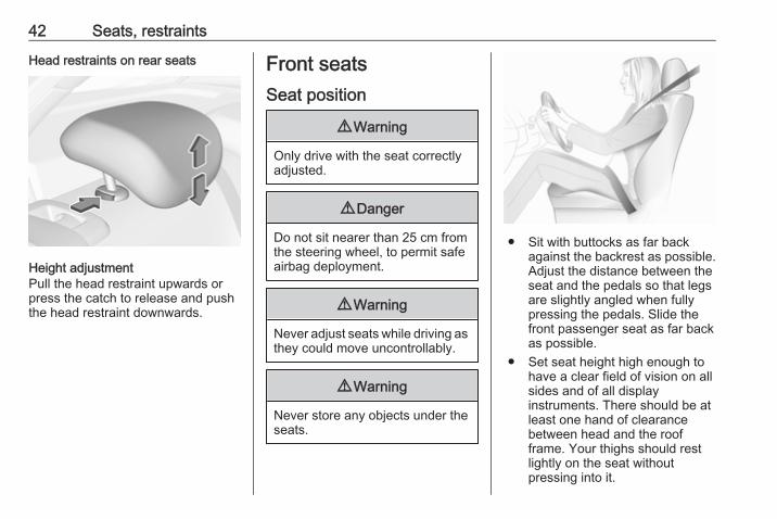
Head restraints on rear seats
Height adjustmentPull the head restraint upwards orpress the catch to release and pushthe head restraint downwards.
Front seatsSeat position
9 Warning
Only drive with the seat correctlyadjusted.
9 Danger
Do not sit nearer than 25 cm fromthe steering wheel, to permit safeairbag deployment.
9 Warning
Never adjust seats while driving asthey could move uncontrollably.
9 Warning
Never store any objects under theseats.
● Sit with buttocks as far backagainst the backrest as possible.Adjust the distance between theseat and the pedals so that legsare slightly angled when fullypressing the pedals. Slide thefront passenger seat as far backas possible.
● Set seat height high enough tohave a clear field of vision on allsides and of all displayinstruments. There should be atleast one hand of clearancebetween head and the roofframe. Your thighs should restlightly on the seat withoutpressing into it.

Seats, restraints 43
● Sit with shoulders as far backagainst the backrest as possible.Set the backrest rake so that it ispossible to easily reach thesteering wheel with arms slightlybent. Maintain contact betweenshoulders and the backrest whenturning the steering wheel. Donot angle the backrest too farback. We recommend amaximum rake of approx. 25°.
● Adjust seat and steering wheel ina way that the wrist rests on topof the steering wheel while thearm is fully extended andshoulders on the backrest.
● Adjust the steering wheel 3 76.● Adjust the head restraint 3 41.● Adjust the thigh support so that
there is a space approx. twofingers wide between the edge ofthe seat and the hollow of theknee.
● Adjust the lumbar support so thatit supports the natural shape ofthe spine.
Manual seat adjustmentDrive only with engaged seats andbackrests.
Longitudinal adjustment
Pull handle, slide seat, releasehandle. Try to move the seat back andforth to ensure that the seat is lockedin place.
Backrest inclination
Turn handwheel. Do not lean onbackrest when adjusting.

44 Seats, restraints
Seat height
Lever pumping motionup : seat higherdown : seat lower
Seat inclination
Press switchtop : front end higherbottom : front end lower
Lumbar support
Adjust lumbar support using the four-way switch to suit personalrequirements.Moving support up and down: pushswitch up or down.Increasing and decreasing support:push switch forwards or backwards.

Seats, restraints 45
Adjustable thigh support
Pull the lever and slide the thighsupport.
Power seat adjustment
9 Warning
Care must be taken whenoperating the power seats. Thereis a risk of injury, particularly forchildren. Objects could becometrapped.
Keep a close watch on the seatswhen adjusting them. Vehiclepassengers should be informedaccordingly.
Longitudinal adjustment
Move switch forwards/backwards.
Seat height
Move switch upwards/downwards.
Seat inclination

46 Seats, restraints
Tilt front of switch upwards/downwards.
Backrest inclination
Tilt switch forwards/backwards.
Lumbar support
Adjust lumbar support using thefour-way switch to suit personalrequirements.Moving support up and down: pushswitch up or down.Increasing and decreasing support:push switch forwards or backwards.
Adjustable thigh support
Pull the lever and slide the thighsupport.

Seats, restraints 47
Side bolster
Adjust seat backrest width to suitpersonal requirements.Press e to reduce backrest width.Press d to increase backrest width.
Memory function for power seatadjustmentTwo different driver's seat settingscan be stored.Memorised settings 3 24, Vehiclepersonalisation 3 107.
Storing memory position● Adjust driver's seat to desired
position.● Press and hold MEM and 1 or 2
simultaneously until a chimesounds.
Recall of memory positionsPress and hold 1 or 2 until the storedseat position has been reached.Releasing the button during seatmovement cancels the recall.
Storing position by remote controlActual driver's seat position isautomatically stored by the radioremote control key each time the
ignition is switched off. These storedpositions are independent of thememory positions stored by thebutton 1 or 2.The stored positions areautomatically recalled by switching onthe ignition.To stop recall movement, press oneof the memory or power seat controls.This function can be activated ordeactivated in the vehiclepersonalisation.Select the relevant setting in theVehicle menu in the Info-Display.Info-Display 3 103.Vehicle personalisation 3 107.
Easy exit functionFor a convenient exit out of thevehicle, the power driver seat movesrearwards when vehicle is stationary.To activate, switch off ignition,remove key from the ignition switchand open the driver's door. If the dooris already open, switch off ignition toactivate the recall.To stop recall movement, press oneof the memory or power seat controls.

48 Seats, restraints
This function can be activated ordeactivated in the vehiclepersonalisation.Select the relevant setting in theVehicle menu in the Info-Display.Info-Display 3 103.Vehicle personalisation 3 107.
Safety functionIf the driver's seat encountersresistance during movement, therecall may stop. After removing theobstruction, press and hold theappropriate memory position buttonfor two seconds. Try recalling thememory position again. If the recalldoes not operate, consult aworkshop.
OverloadIf the seat setting is electricallyoverloaded, the power supply isautomatically cut-off for a short time.NoteAfter an accident in which airbagshave been deployed, the memoryfunction for each position button willbe deactivated.
Armrest
The armrest can be slid forwards by10 cm. Under the armrest there is astorage compartment.Armrest storage 3 67.
Heating
Adjust heating to the desired settingby pressing ß for the respective seatone or more times. The controlindicator in the button indicates thesetting.Prolonged use of the highest settingfor people with sensitive skin is notrecommended.The seat heating will be reducedautomatically from highest level tomedium level after 30 minutes.Seat heating is operational whenengine is running and during anAutostop.

Seats, restraints 49
Stop-start system 3 145.
Automatic seat heatingDepending on the equipment, theautomatic seat heating can beenabled in the vehicle personalisationmenu in the Info-Display.Vehicle personalisation 3 107.When enabled, the heating of theseats will be activated automaticallyat vehicle start. The activation isbased on several parameters such asvehicle interior temperature, intensityand direction of the sun andtemperature setting of the electronicclimate control system for the driverand passenger side.As the vehicle’s interior warms up, theseat heating level will be reducedautomatically until it finally goes off.The seat heating level being providedduring the automatic operation isshown by heated seat indicator lights.If the passenger seat is unoccupied,the automatic seat heating feature willnot activate the seat heating for thatseat.
The seat heating buttons can bepressed at any time to exit theautomatic seat heating for therespective seat and control the seatheating manually instead.
Ventilating
Adjust ventilating to the desiredsetting by pressing A for therespective seat one or more times.The control indicator in the buttonindicates the setting.Ventilated seats are operational whenengine is running and during anAutostop.Stop-start system 3 145.
Massage
Press c to switch on the backmassage function. To switch off,press c again.

50 Seats, restraints
Rear seatsArmrest
Fold armrest down.
Heating
Activate seat heating by pressing ßfor the respective rear outer seat.Activation is indicated by the LED inthe button.Press ß once more to deactivate seatheating.Prolonged use for people withsensitive skin is not recommended.Seat heating is operational whenengine is running and during anAutostop.Stop-start system 3 145.
Seat belts
The seat belts are locked duringheavy acceleration or deceleration ofthe vehicle holding the occupants inthe sitting position. Thereby the risk ofinjury is considerably reduced.
9 Warning
Fasten seat belt before each trip.In the event of an accident, peoplenot wearing seat belts endangertheir fellow occupants andthemselves.

Seats, restraints 51
Seat belts are designed to be used byonly one person at a time. Childrestraint system 3 59.Periodically check all parts of the beltsystem for damage, pollution andproper functionality.Have damaged componentsreplaced. After an accident, have thebelts and triggered belt pretensionersreplaced by a workshop.NoteMake sure that the belts are notdamaged by shoes or sharp-edgedobjects or trapped. Prevent dirt fromgetting into the belt retractors.
Seat belt reminderEach seat is equipped with a seat beltreminder, indicated for front seats bycontrol indicators X and k, or for rearseats by the symbol X in the DriverInformation Centre 3 92.
Belt force limitersStress on the body is reduced by thegradual release of the belt during acollision.
Belt pretensionersIn the event of a head-on, rear-end orside-on collision of a certain severity,the front and rear seat belts aretightened. The front seat belts aretightened by two pretensioners perseat. The outer rear seat belts aretightened by one pretensioner perseat.
9 Warning
Incorrect handling (e.g. removal orfitting of belts) can trigger the beltpretensioners.
Deployment of the belt pretensionersis indicated by continuous illuminationof control indicator v 3 93.Triggered belt pretensioners must bereplaced by a workshop. Beltpretensioners can only be triggeredonce.NoteDo not affix or install accessories orother objects that may interfere withthe operation of the beltpretensioners. Do not make any
modifications to belt pretensionercomponents as this will invalidatethe vehicle type approval.
Three-point seat beltFastening
Withdraw the belt from the retractor,guide it untwisted across the bodyand insert the latch plate into thebuckle. Tighten the lap belt regularlywhilst driving by pulling the shoulderbelt.

52 Seats, restraints
Loose or bulky clothing prevents thebelt from fitting snugly. Do not placeobjects such as handbags or mobilephones between the belt and yourbody.
9 Warning
The belt must not rest against hardor fragile objects in the pockets ofyour clothing.
Seat belt reminder X, k 3 92.
Removing
To release belt, press red button onbelt buckle.
Using the seat belt while pregnant
9 Warning
The lap belt must be positioned aslow as possible across the pelvisto prevent pressure on theabdomen.

Seats, restraints 53
Airbag systemThe airbag system consists of anumber of individual systemsdepending on the scope ofequipment.When triggered, the airbags inflatewithin milliseconds. They also deflateso quickly that it is often unnoticeableduring the collision.
9 Warning
If handled improperly, the airbagsystems can be triggered in anexplosive manner.
NoteThe airbag systems and beltpretensioner control electronics arelocated in the centre console area.Do not put any magnetic objects inthis area.Do not stick anything on the airbagcovers and do not cover them withother materials.Each airbag is triggered only once.Have deployed airbags replaced bya workshop. Furthermore, it might be
necessary to have the steeringwheel, the instrument panel, parts ofthe panelling, the door seals,handles and the seats replaced.Do not make any modifications tothe airbag system as this willinvalidate the vehicle type approval.
When the airbags inflate, escapinghot gases may cause burns.Control indicator v for airbag systems3 93.
Child restraint systems on frontpassenger seat with airbagsystemsWarning according to ECE R94.02:
EN: NEVER use a rearward-facingchild restraint on a seat protected byan ACTIVE AIRBAG in front of it;DEATH or SERIOUS INJURY to theCHILD can occur.DE: Nach hinten gerichteteKindersitze NIEMALS auf einem Sitzverwenden, der durch einen davorbefindlichen AKTIVEN AIRBAGgeschützt ist, da dies den TOD oderSCHWERE VERLETZUNGEN DESKINDES zur Folge haben kann.FR: NE JAMAIS utiliser un sièged'enfant orienté vers l'arrière sur unsiège protégé par un COUSSINGONFLABLE ACTIF placé devant lui,sous peine d'infliger desBLESSURES GRAVES, voireMORTELLES à l'ENFANT.ES: NUNCA utilice un sistema deretención infantil orientado haciaatrás en un asiento protegido por unAIRBAG FRONTAL ACTIVO. Peligrode MUERTE o LESIONES GRAVESpara el NIÑO.RU: ЗАПРЕЩАЕТСЯустанавливать детскоеудерживающее устройство лицомназад на сиденье автомобиля,

54 Seats, restraints
оборудованном фронтальнойподушкой безопасности, еслиПОДУШКА НЕ ОТКЛЮЧЕНА! Этоможет привести к СМЕРТИ илиСЕРЬЕЗНЫМ ТРАВМАМРЕБЕНКА.NL: Gebruik NOOIT een achterwaartsgericht kinderzitje op een stoel meteen ACTIEVE AIRBAG ervoor, omDODELIJK of ERNSTIG LETSEL vanhet KIND te voorkomen.DA: Brug ALDRIG en bagudvendtautostol på et forsæde med AKTIVAIRBAG, BARNET kan komme iLIVSFARE eller komme ALVORLIGTTIL SKADE.SV: Använd ALDRIG en bakåtvändbarnstol på ett säte som skyddas meden framförvarande AKTIV AIRBAG.DÖDSFALL eller ALLVARLIGASKADOR kan drabba BARNET.FI: ÄLÄ KOSKAAN sijoita taaksepäinsuunnattua lasten turvaistuintaistuimelle, jonka edessä onAKTIIVINEN TURVATYYNY, LAPSIVOI KUOLLA tai VAMMAUTUAVAKAVASTI.
NO: Bakovervendtbarnesikringsutstyr må ALDRI brukespå et sete med AKTIVKOLLISJONSPUTE foran, da det kanføre til at BARNET utsettes forLIVSFARE og fare for ALVORLIGESKADER.PT: NUNCA use um sistema deretenção para crianças voltado paratrás num banco protegido com umAIRBAG ACTIVO na frente domesmo, poderá ocorrer a PERDA DEVIDA ou FERIMENTOS GRAVES naCRIANÇA.IT: Non usare mai un sistema disicurezza per bambini rivoltoall'indietro su un sedile protetto daAIRBAG ATTIVO di fronte ad esso:pericolo di MORTE o LESIONIGRAVI per il BAMBINO!EL: ΠΟΤΕ μη χρησιμοποιείτε παιδικόκάθισμα ασφαλείας με φορά προς ταπίσω σε κάθισμα που προστατεύεταιαπό μετωπικό ΕΝΕΡΓΟ ΑΕΡΟΣΑΚΟ,διότι το παιδί μπορεί να υποστείΘΑΝΑΣΙΜΟ ή ΣΟΒΑΡΟΤΡΑΥΜΑΤΙΣΜΟ.
PL: NIE WOLNO montować fotelikadziecięcego zwróconego tyłem dokierunku jazdy na fotelu, przedktórym znajduje się WŁĄCZONAPODUSZKA POWIETRZNA.Niezastosowanie się do tegozalecenia może być przyczynąŚMIERCI lub POWAŻNYCHOBRAŻEŃ u DZIECKA.TR: Arkaya bakan bir çocuk emniyetsistemini KESİNLİKLE önünde birAKTİF HAVA YASTIĞI ilekorunmakta olan bir koltuktakullanmayınız. ÇOCUK ÖLEBİLİRveya AĞIR ŞEKİLDEYARALANABİLİR.UK: НІКОЛИ не використовуйтесистему безпеки для дітей, щовстановлюється обличчям назад,на сидінні з УВІМКНЕНОЮПОДУШКОЮ БЕЗПЕКИ, інакше цеможе призвести до СМЕРТІ чиСЕРЙОЗНОГО ТРАВМУВАННЯДИТИНИ.HU: SOHA ne használjon hátrafelénéző biztonsági gyerekülést előlrőlAKTÍV LÉGZSÁKKAL védett ülésen,mert a GYERMEK HALÁLÁT vagyKOMOLY SÉRÜLÉSÉT okozhatja.

Seats, restraints 55
HR: NIKADA nemojte koristiti sustavzadržavanja za djecu okrenut premanatrag na sjedalu s AKTIVNIMZRAČNIM JASTUKOM ispred njega,to bi moglo dovesti do SMRTI iliOZBILJNJIH OZLJEDA za DIJETE.SL: NIKOLI ne nameščajte otroškegavarnostnega sedeža, obrnjenega vnasprotni smeri vožnje, na sedež zAKTIVNO ČELNO ZRAČNOBLAZINO, saj pri tem obstajanevarnost RESNIH ali SMRTNIHPOŠKODB za OTROKA.SR: NIKADA ne koristiti bezbednosnisistem za decu u kome su decaokrenuta unazad na sedištu saAKTIVNIM VAZDUŠNIMJASTUKOM ispred sedišta zato štoDETE može da NASTRADA ili da seTEŠKO POVREDI.MK: НИКОГАШ не користете детскоседиште свртено наназад наседиште заштитено со АКТИВНОВОЗДУШНО ПЕРНИЧЕ пред него,затоа што детето може ДА ЗАГИНЕили да биде ТЕШКО ПОВРЕДЕНО.BG: НИКОГА не използвайтедетска седалка, гледаща назад,върху седалка, която е защитена
чрез АКТИВНА ВЪЗДУШНАВЪЗГЛАВНИЦА пред нея - може дасе стигне до СМЪРТ илиСЕРИОЗНО НАРАНЯВАНЕ наДЕТЕТО.RO: Nu utilizaţi NICIODATĂ un scaunpentru copil îndreptat spre partea dinspate a maşinii pe un scaun protejatde un AIRBAG ACTIV în faţa sa;acest lucru poate duce la DECESULsau VĂTĂMAREA GRAVĂ aCOPILULUI.CS: NIKDY nepoužívejte dětskýzádržný systém instalovaný protisměru jízdy na sedadle, které jechráněno před sedadlem AKTIVNÍMAIRBAGEM. Mohlo by dojít kVÁŽNÉMU PORANĚNÍ nebo ÚMRTÍDÍTĚTE.SK: NIKDY nepoužívajte detskúsedačku otočenú vzad na sedadlechránenom AKTÍVNYM AIRBAGOM,pretože môže dôjsť k SMRTI aleboVÁŽNYM ZRANENIAM DIEŤAŤA.LT: JOKIU BŪDU nemontuokite atgalatgręžtos vaiko tvirtinimo sistemossėdynėje, prieš kurią įrengta AKTYVIORO PAGALVĖ, nes VAIKAS GALIŽŪTI arba RIMTAI SUSIŽALOTI.
LV: NEKĀDĀ GADĪJUMĀneizmantojiet uz aizmuguri vērstubērnu sēdeklīti sēdvietā, kas tiekaizsargāta ar tās priekšā uzstādītuAKTĪVU DROŠĪBAS SPILVENU, jopretējā gadījumā BĒRNS var gūtSMAGAS TRAUMAS vai IET BOJĀ.ET: ÄRGE kasutage tahapoolesuunatud lapseturvaistet istmel, milleees on AKTIIVSE TURVAPADJAGAkaitstud iste, sest see võibpõhjustada LAPSE SURMA võiTÕSISE VIGASTUSE.MT: QATT tuża trażżin għat-tfal lijħares lejn in-naħa ta’ wara fuq sitprotett b’AIRBAG ATTIV quddiemu;dan jista’ jikkawża l-MEWT jewĠRIEĦI SERJI lit-TFAL.Beyond the warning required byECE R94.02, for safety reasons aforward-facing child restraint systemmust only be used subject to theinstructions and restrictions in thetable 3 62.The airbag label is located on bothsides of the front passenger sun visor.Airbag deactivation 3 57.

56 Seats, restraints
Front airbag systemThe front airbag system consists ofone airbag in the steering wheel andone in the instrument panel on thefront passenger side. These can beidentified by the word AIRBAG.The front airbag system is triggered inthe event of a front-end impact of acertain severity. The ignition must beswitched on.
The inflated airbags cushion theimpact, thereby reducing the risk ofinjury to the upper body and head ofthe front seat occupantsconsiderably.
9 Warning
Optimum protection is onlyprovided when the seat is in theproper position.Seat position 3 42.Keep the area in which the airbaginflates clear of obstructions.Fit the seat belt correctly andengage securely. Only then is theairbag able to protect.
Side airbag system
The side airbag system consists of anairbag in each front seat backrest.This can be identified by the wordAIRBAG.The side airbag system is triggered inthe event of a side impact of a certainseverity. The ignition must beswitched on.
The inflated airbags cushion theimpact, thereby reducing the risk ofinjury to the upper body and pelvis inthe event of a side-on collisionconsiderably.

Seats, restraints 57
9 Warning
Keep the area in which the airbaginflates clear of obstructions.
NoteOnly use protective seat covers thathave been approved for the vehicle.Be careful not to cover the airbags.
Curtain airbag systemThe curtain airbag system consists ofan airbag in the roof frame on eachside. This can be identified by theword AIRBAG on the roof pillars.The curtain airbag system is triggeredin the event of a side-on impact of acertain severity. The ignition must beswitched on.
The inflated airbags cushion theimpact, thereby reducing the risk ofinjury to the head in the event of aside-on impact considerably.
9 Warning
Keep the area in which the airbaginflates clear of obstructions.The hooks on the handles in theroof frame are only suitable forhanging up light articles ofclothing, without coat hangers. Donot keep any items in theseclothes.
Airbag deactivationThe front passenger airbag systemmust be deactivated for child restraintsystem on the passenger seataccording to the instructions in thetable 3 62. The side airbag andcurtain airbag systems, the beltpretensioners and all driver airbagsystems will remain active.
The front passenger airbag systemcan be deactivated via a key-operated switch on the right side ofthe instrument panel.

58 Seats, restraints
Use the ignition key to choose theposition:*OFF : front passenger airbag is
deactivated and will notinflate in the event of acollision. Control indicator*OFF illuminatescontinuously in the centreconsole
VON : front passenger airbag isactive
9 Danger
Deactivate passenger airbag onlyin combination with the use of achild restraint system, subject tothe instructions and restrictions inthe table 3 62.Otherwise, there is a risk of fatalinjury for a person occupying aseat with a deactivated frontpassenger airbag.
If the control indicator V illuminatesfor approx. 60 seconds after theignition is switched on, the frontpassenger airbag system will inflatein the event of a collision.If both control indicators areilluminated at the same time, there isa system failure. The status of thesystem is not discernible, thereforeno person is allowed to occupy thefront passenger seat. Contact aworkshop immediately.Consult a workshop immediately ifneither of the two control indicatorsare illuminated.Change status only when the vehicleis stopped with the ignition off.
Status remains until the next change.Control indicator for airbagdeactivation 3 93.

Seats, restraints 59
Child restraintsChild restraint systems
9 Danger
If using a rear-facing child restraintsystem on the front passengerseat, the airbag system for thefront passenger seat must bedeactivated. This also applies tocertain forward-facing childrestraint systems as indicated inthe tables 3 62.
Airbag deactivation 3 57, Airbag label3 53.We recommend a child restraintsystem which is tailored specifically tothe vehicle. For further information,contact your workshop.When a child restraint system is beingused, pay attention to the followingusage and installation instructionsand also those supplied with the childrestraint system.
Always comply with local or nationalregulations. In some countries, theuse of child restraint systems isforbidden on certain seats.Child restraint systems can befastened with:● Three-point seat belt● ISOFIX brackets● Top-tether
Three-point seat beltChild restraint systems can befastened by using a three-point seatbelt. Depending on the size of theused child restraint systems, up tothree child restraint systems can beattached to the rear seats 3 62.
ISOFIX brackets
Fasten vehicle-approved ISOFIXchild restraint systems to the ISOFIXmounting brackets. Specific vehicleISOFIX child restraint systempositions are marked in the ISOFIXtable 3 62.ISOFIX mounting brackets areindicated by a label on the backrest.An i-Size child restraint system is anuniversal ISOFIX child restraintsystem according UN Regulation No.129.All i-Size child restraint systems canbe used on any vehicle seat suitablefor i-Size, i-Size table 3 62.

60 Seats, restraints
Either a Top-tether strap or a supportleg must be used in addition to theISOFIX mounting brackets.
i-Size child seats and vehicle seatswith i-Size approval are marked withi-Size symbol, see illustration.
Top-tether fastening eyesTop-tether fastening eyes are markedwith the symbol : for a child seat.
In addition to the ISOFIX mountingbrackets, fasten the Top-tether strapto the Top-tether fastening eyes. Thestrap must run between the two guiderods of the head restraint.ISOFIX child restraint systems ofuniversal category positions aremarked in the table by IUF 3 62.
Selecting the right systemThe rear seats are the mostconvenient location to fasten a childrestraint system.Children should travel facingrearwards in the vehicle as long aspossible. This makes sure that the
child's backbone, which is still veryweak, is under less strain in the eventof an accident.Suitable are restraint systems thatcomply with valid UN ECEregulations. Check local laws andregulations for mandatory use of childrestraint systems.The following child restraints arerecommended for the followingweight classes:Maxi Cosi Cabriofix for children up to13 kg for group 0, group 0+ and DuoPlus for children from 13 kg to 18 kgin group I.Ensure that the child restraint systemto be installed is compatible with thevehicle type.Ensure that the mounting location ofthe child restraint system within thevehicle is correct, see followingtables.Allow children to enter and exit thevehicle only on the side facing awayfrom the traffic.When the child restraint system is notin use, secure the seat with a seat beltor remove it from the vehicle.

Seats, restraints 61
NoteDo not affix anything on the childrestraint systems and do not coverthem with any other materials.A child restraint system which hasbeen subjected to stress in anaccident must be replaced.
62 Seats, restraints
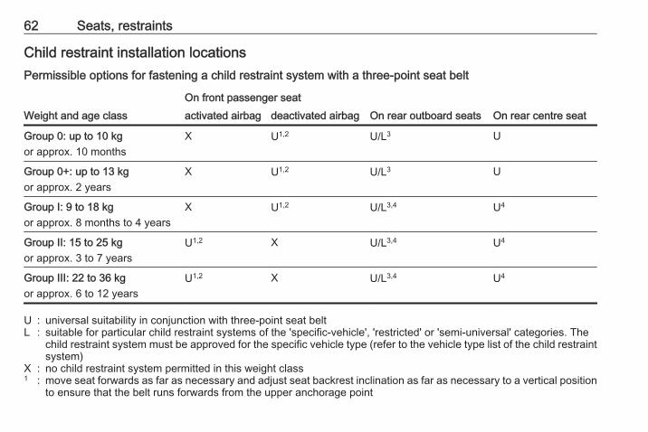
Child restraint installation locationsPermissible options for fastening a child restraint system with a three-point seat belt
Weight and age classOn front passenger seat
On rear outboard seats On rear centre seatactivated airbag deactivated airbag
Group 0: up to 10 kgor approx. 10 months
X U1,2 U/L3 U
Group 0+: up to 13 kgor approx. 2 years
X U1,2 U/L3 U
Group I: 9 to 18 kgor approx. 8 months to 4 years
X U1,2 U/L3,4 U4
Group II: 15 to 25 kgor approx. 3 to 7 years
U1,2 X U/L3,4 U4
Group III: 22 to 36 kgor approx. 6 to 12 years
U1,2 X U/L3,4 U4
U : universal suitability in conjunction with three-point seat beltL : suitable for particular child restraint systems of the 'specific-vehicle', 'restricted' or 'semi-universal' categories. The
child restraint system must be approved for the specific vehicle type (refer to the vehicle type list of the child restraintsystem)
X : no child restraint system permitted in this weight class1 : move seat forwards as far as necessary and adjust seat backrest inclination as far as necessary to a vertical position
to ensure that the belt runs forwards from the upper anchorage point

Seats, restraints 632 : move seat height adjustment upwards as far as necessary and adjust seat backrest inclination as far as necessary
to a vertical position to ensure that the belt is tight on the buckle side3 : move the respective front seat ahead of the child restraint system forwards as far as necessary4 : adjust the respective headrest as necessary or remove if required
Permissible options for fitting an ISOFIX child restraint system with ISOFIX brackets
Weight and age class Size class Fixture
On front passenger seatOn rearoutboard seats
On rearcentre seat
activatedairbag
deactivatedairbag
Group 0: up to 10 kgor approx. 10 months
G ISO/L2 X X X X
F ISO/L1 X X X X
E ISO/R1 X X IL3 X
Group 0+: up to 13 kgor approx. 2 years
E ISO/R1 X X IL3 X
D ISO/R2 X X IL3 X
C ISO/R3 X X IL3 X
Group I: 9 to 18 kgor approx. 8 months to 4 years
D ISO/R2 X X IL3,4 X
C ISO/R3 X X IL3,4 X
B ISO/F2 X X IL, IUF3,4 X
B1 ISO/F2X X X IL, IUF3,4 X
A ISO/F3 X X IL, IUF3,4 X

64 Seats, restraints
Weight and age class Size class Fixture
On front passenger seatOn rearoutboard seats
On rearcentre seat
activatedairbag
deactivatedairbag
Group II: 15 to 25 kgor approx. 3 to 7 years
X X IL3,4 X
Group III: 22 to 36 kgor approx. 6 to 12 years
X X IL3,4 X
IL : suitable for particular ISOFIX restraint systems of the 'specific-vehicle', 'restricted' or 'semi-universal' categories.The ISOFIX restraint system must be approved for the specific vehicle type (refer to the vehicle type list of the childrestraint system)
IUF : suitable for ISOFIX forward-facing child restraint systems of universal category approved for use in this weight classX : no ISOFIX child restraint system approved in this weight class1 : move seat forwards as far as necessary and adjust seat backrest inclination as far as necessary to a vertical position
to ensure that the belt runs forwards from the upper anchorage point2 : move seat height adjustment upwards as far as necessary and adjust seat backrest inclination as far as necessary
to a vertical position to ensure that the belt is tight on the buckle side3 : move the respective front seat ahead of the child restraint system forwards as far as necessary4 : adjust the respective headrest as necessary or remove if required
ISOFIX size class and seat deviceA – ISO/F3 : forward-facing child restraint system for children of maximum size in the weight class 9 to 18 kgB – ISO/F2 : forward-facing child restraint system for smaller children in the weight class 9 to 18 kgB1 – ISO/F2X : forward-facing child restraint system for smaller children in the weight class 9 to 18 kgC – ISO/R3 : rear-facing child restraint system for children of maximum size in the weight class up to 18 kgD – ISO/R2 : rear-facing child restraint system for smaller children in the weight class up to 18 kgE – ISO/R1 : rear-facing child restraint system for young children in the weight class up to 13 kg
Seats, restraints 65
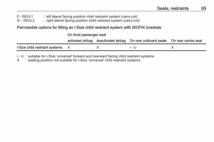
F– ISO/L1 : left lateral facing position child restraint system (carry-cot)G – ISO/L2 : right lateral facing position child restraint system (carry-cot)
Permissible options for fitting an i-Size child restraint system with ISOFIX brackets
On front passenger seatOn rear outboard seats On rear centre seatactivated airbag deactivated airbag
i-Size child restraint systems X X i - U X
i - U : suitable for i-Size 'universal' forward and rearward facing child restraint systemsX : seating position not suitable for i-Size 'universal' child restraint systems

66 Storage
Storage
Storage compartments ................ 66Glovebox ................................... 66Cupholders ................................ 66Front storage ............................. 67Armrest storage ......................... 67
Load compartment ....................... 68Load compartment cover ........... 70Rear floor storage cover ............ 71Lashing eyes ............................. 71Warning triangle ........................ 72First aid kit ................................. 72
Roof rack system ......................... 73Roof rack ................................... 73
Loading information ..................... 73
Storage compartments
9 Warning
Do not store heavy or sharpobjects in the storagecompartments. Otherwise, thestorage compartment lid couldopen and vehicle occupants couldbe injured by objects being thrownaround in the event of hardbraking, a sudden change indirection or an accident.
Glovebox
The glovebox features a pen holder,a coin holder and an adapter for thelocking wheel nuts.The glovebox may also contain a CDplayer and a tool for removing thefuse cover with power connector.The glovebox should be closed whilstdriving.
Cupholders
Cupholders are located in the centreconsole.

Storage 67
Depending on the version,cupholders are located under a coverin the centre console. Slide coverbackwards.
Front storage
A storage compartment is locatednext to the steering wheel.
Armrest storageStorage under the front armrest
Press button to fold up the armrest.The armrest must be in rearmostposition.
68 Storage
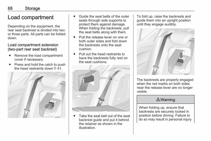
Load compartmentDepending on the equipment, therear seat backrest is divided into twoor three parts. All parts can be foldeddown.
Load compartment extension(two-part rear seat backrest)● Remove the load compartment
cover if necessary.● Press and hold the catch to push
the head restraints down 3 41.
● Guide the seat belts of the outerseats through side supports toprotect them against damage.When folding the backrests, pullthe seat belts along with them.
● Pull the release lever on one orboth outer sides and fold downthe backrests onto the seatcushion.
● Pull out the head restraints tohave the backrests fully rest onthe seat cushions.
● Take the seat belt out of the seatbackrest guide and put it behindthe retainer as shown in theillustration.
To fold up, raise the backrests andguide them into an upright positionuntil they engage audibly.
The backrests are properly engagedwhen the red marks on both sidesnear the release lever are no longervisible.
9 Warning
When folding up, ensure thatbackrests are securely locked inposition before driving. Failure todo so may result in personal injury

Storage 69
or damage to the load or vehicle inthe event of hard braking or acollision.
The seat belt of the centre seat couldbe blocked when the backrest isfolded up too quickly. To unlock theretractor, push in the seat belt or pullit out by approx. 20 mm then release.
Load compartment extension(three-part rear seat backrest)● Remove the load compartment
cover if necessary.● Press and hold the catch to push
the head restraints down 3 41.
● Fold up the rear armrest.
● Pull the handle and fold down thebackrest of the centre seat.
● Pull the release lever on one orboth outer sides and fold downthe backrests onto the seatcushion.
9 Warning
Take care when folding down theright outer seat backrest if thecentre seat backrest is alreadyfolded down. Risk of injury due tobolt protruding from the inner sideof the backrest.
● Guide the seat belts of the outerseats through side supports toprotect them against damage.When folding the backrests, pullthe seat belts along with them.
● Pull out the head restraints to getthe backrests fully rest on theseat cushions.

70 Storage
● Take the seat belt out of the seatbackrest guide and put it behindthe retainer as shown in theillustration.
To fold up, raise the backrests andguide them into an upright positionuntil they engage audibly.
The backrests are properly engagedwhen the red marks on both sidesnear the release lever are no longervisible.
9 Warning
When folding up, ensure thatbackrests are securely locked inposition before driving. Failure todo so may result in personal injuryor damage to the load or vehicle inthe event of hard braking or acollision.
The seat belt of the centre seat couldbe blocked when the backrest isfolded up too quickly. To unlock theretractor, push in the seat belt or pullit out by approx. 20 mm then release.
Load compartment coverDo not place any objects on the cover.

Storage 71
Removing
Unhook retaining straps from tailgate.
Lift cover at the rear and push itupwards at the front.
Remove the cover.
FittingEngage cover in side guides and folddownwards. Attach retaining straps totailgate.
Rear floor storage coverRear floor cover
The rear floor cover can be removed.Raise cover at the rear and slightlyrotate at one side before removing.
Lashing eyesThe lashing eyes are designed tosecure items against slippage, e.g.using lashing straps or luggage net.First remove the rear floor storagecover to get access to the lashingeyes.
On vehicles equipped with a sparewheel, the front lashing eyes arelocated at the sidewalls.

72 Storage
On vehicles equipped with tyre repairkit, the front lashing eyes are locatedunderneath the rear floor coverbehind the rear seats. To get accessto the lashing eyes, open theperforated parts of the cover by usingthe screwdriver. Vehicle tools 3 218.Stick the screwdriver through thecover as shown in the illustration andfold up the perforated part of thecover.Fold up the lashing eyes by using thescrewdriver.
Warning triangle
Stow the warning triangle in therecess.
First aid kit
Stow the first aid kit in thecompartment.To open the compartment, disengagecover and open it.

Storage 73
Roof rack systemRoof rackFor safety reasons and to avoiddamage to the roof, the vehicleapproved roof rack system isrecommended. For furtherinformation contact your workshop.Remove the roof rack when not inuse.
Mounting roof rack
Open all doors.Mounting points are located in eachdoor frame of the vehicle body.
Fasten the roof rack according to theinstallation instructions delivered withthe roof rack.
Loading information
● Heavy objects in the loadcompartment should be placedagainst the seat backrests.Ensure that the backrests aresecurely engaged. If objects canbe stacked, heavier objectsshould be placed at the bottom.
● Secure objects with lashingstraps attached to lashing eyes3 71.
● Secure loose objects in the loadcompartment to prevent themfrom sliding.

74 Storage
● Do not allow the load to protrudeabove the upper edge of thebackrests.
● Do not place any objects on theload compartment cover or theinstrument panel, and do notcover the sensor on top of theinstrument panel.
● The load must not obstruct theoperation of the pedals, parkingbrake and gear selector lever, orhinder the freedom of movementof the driver. Do not place anyunsecured objects in the interior.
● Do not drive with an open loadcompartment.
9 Warning
Always make sure that the load inthe vehicle is securely stowed.Otherwise objects can be thrownaround inside the vehicle andcause personal injury or damageto the load or car.
● The payload is the differencebetween the permitted grossvehicle weight (see identification
plate 3 243) and the EC kerbweight.To calculate the payload, enterthe data for your vehicle in theweights table at the front of thismanual.The EC kerb weight includesweights for the driver (68 kg),luggage (7 kg) and all fluids (fueltank 90% full).Optional equipment andaccessories increase the kerbweight.
● Driving with a roof load increasesthe sensitivity of the vehicle tocross-winds and has adetrimental effect on vehiclehandling due to the vehicle'shigher centre of gravity.Distribute the load evenly andsecure it properly with retainingstraps. Adjust the tyre pressureand vehicle speed according tothe load conditions. Check andretighten the straps frequently.Do not drive faster than120 km/h.
The permissible roof load is75 kg. The roof load is thecombined weight of the roof rackand the load.

Instruments and controls 75
Instruments andcontrols
Controls ....................................... 76Steering wheel adjustment ........ 76Steering wheel controls ............. 76Heated steering wheel ............... 77Horn ........................................... 77Windscreen wiper/washer ......... 77Rear window wiper/washer ....... 79Outside temperature .................. 80Clock ......................................... 80Power outlets ............................. 82Power connector ....................... 83Ashtrays .................................... 84
Warning lights, gauges and indi‐cators ........................................... 85
Instrument cluster ...................... 85Speedometer ............................. 88Odometer .................................. 89Trip odometer ............................ 89Tachometer ............................... 90Fuel gauge ................................ 90Engine coolant temperaturegauge ....................................... 90
Service display .......................... 91Control indicators ...................... 92
Turn signal ................................. 92Seat belt reminder ..................... 92Airbag and belt tensioners ......... 93Airbag deactivation .................... 93Charging system ....................... 93Malfunction indicator light .......... 94Brake and clutch system ........... 94Electric parking brake ................ 94Electric parking brake fault ........ 94Antilock brake system (ABS) ..... 95Gear shifting .............................. 95Following distance ..................... 95Lane keep assist ....................... 95Electronic Stability Control off . . . 95Electronic Stability Control andTraction Control system ........... 95
Traction Control system off ....... 96Preheating ................................. 96Tyre pressure monitoringsystem ...................................... 96
Engine oil pressure .................... 96Low fuel ..................................... 96Immobiliser ................................ 97Exterior light .............................. 97High beam ................................. 97High beam assist ....................... 97LED headlights .......................... 97Fog light ..................................... 97Rear fog light ............................. 97Cruise control ............................ 97
Vehicle detected ahead ............. 97Speed limiter ............................. 97Traffic sign assistant .................. 98Door open .................................. 98
Information displays ..................... 98Driver Information Centre .......... 98Info display .............................. 103
Vehicle messages ...................... 105Warning chimes ....................... 106Battery voltage ........................ 107
Vehicle personalisation .............. 107OnStar® system ........................ 114

76 Instruments and controls
ControlsSteering wheel adjustment
Unlock lever, adjust steering wheel,then engage lever and ensure it isfully locked.Do not adjust steering wheel unlessvehicle is stationary and steeringwheel lock has been released.
Steering wheel controlsDriver Information Centre, somedriver assistance systems,Infotainment system and a connectedmobile phone can be operated via thecontrols on the steering wheel.
The illustrations show differentversions.
Driver Information Centre 3 98.Driver assistance systems 3 163.Further information is available in theInfotainment manual.

Instruments and controls 77
Heated steering wheel
Activate heating by pressing *.Activation is indicated by the LED inthe button.
The recommended grip areas of thesteering wheel are heated quickerand to a higher temperature than theother areas.Heating is operational when theengine is running and during anAutostop.Stop-start system 3 145.
Horn
Press j.
Windscreen wiper/washerWindscreen wiper with adjustablewiper intervall
HI : fastLO : slowINT : interval wipingOFF : off
For a single wipe when thewindscreen wiper is off, press thelever downwards to position 1x.Do not use if the windscreen is frozen.Switch off in car washes.

78 Instruments and controls
Adjustable wiper interval
Wiper lever in position INT.Turn the adjuster wheel to adjust thedesired wipe interval:short interval : turn adjuster
wheel upwardslong interval : turn adjuster
wheel downwards
Windscreen wiper with rainsensor
HI : fastLO : slowAUTO : automatic wiping with rain
sensorOFF : off
In AUTO position the rain sensordetects the amount of water on thewindscreen and automaticallyregulates the frequency of thewindscreen wiper.For a single wipe when thewindscreen wiper is off, press thelever downwards to position 1x.Do not use if the windscreen is frozen.
Switch off in car washes.
Adjustable sensitivity of the rainsensor
Wiper lever in position AUTO.Turn the adjuster wheel to adjust thesensitivity:low sensitivity : turn adjuster
wheel downwardshigh sensitivity : turn adjuster
wheel upwards

Instruments and controls 79
Keep the sensor free from dust, dirtand ice.Rain sensor function can be activatedor deactivated in the Vehiclepersonalisation.Select the relevant setting in Settings,I Vehicle in the Info-Display.Info-Display 3 103.Vehicle personalisation 3 107.
Windscreen washer
Pull lever. Washer fluid is sprayedonto the windscreen and the wiperwipes a few times.Washer fluid 3 200
Rear window wiper/washer
Turn outer cap to activate the rearwindow wiper:ON : continuous operationINT : intermittent operationOFF : off
Do not use if the rear window isfrozen.Switch off in car washes.The rear window wiper comes onautomatically when the windscreenwiper is switched on and reverse gearis engaged.

80 Instruments and controls
Activation or deactivation of thisfunction can be changed in the menuSettings in the Info-Display.Vehicle personalisation 3 107.
Rear window washer
Push lever.Washer fluid is sprayed onto the rearwindow and the wiper wipes a fewtimes.The rear window washer system isdeactivated when the fluid level islow.Washer fluid 3 200
Outside temperatureA drop in temperature is indicatedimmediately and a rise in temperatureafter a time delay.
Illustration shows an example.
If outside temperature drops to 3 °C,a warning message is displayed in theDriver Information Centre.
9 Warning
The road surface may already beicy even though the displayindicates a few degrees above0 °C.
ClockDate and time are shown in theInfo-Display.Info-Display 3 103

Instruments and controls 81
Graphic-Info-DisplayPress MENU to open the respectiveaudio menu.
Select Time and Date.
Set TimeSelect Set Time to enter therespective submenu.Select Auto Set at the bottom of thescreen. Activate either On - RDS orOff (Manual).If Off (Manual) is selected, adjusthours and minutes.Repeatedly select 12-24 HR at thebottom of the screen to choose a timemode.If the 12-hour mode is selected, athird column for AM and PM selectionis displayed. Select the desiredoption.
Set DateSelect Set Date to enter therespective submenu.Select Auto Set at the bottom of thescreen. Activate either On - RDS orOff (Manual).If Off (Manual) is selected, adjust thedate settings.
7'' Colour-Info-DisplayPress ; and then select Settings.Select Time and Date to display therespective submenu.
Set Time FormatTo select the desired time format,touch the screen buttons 12 h or 24 h.
Set Date FormatTo select the desired date format,select Set Date Format and choosebetween the available options in thesubmenu.
Auto SetTo choose whether time and date areto be set automatically or manually,select Auto Set.For time and date to be setautomatically, select On - RDS.For time and date to be set manually,select Off - Manual. If Auto Set is setto Off - Manual, the submenu itemsSet Time and Set Date becomeavailable.
Set time and dateTo adjust the time and date settings,select Set Time or Set Date.Touch + and - to adjust the settings.

82 Instruments and controls
8'' Colour-Info-DisplayPress ; and then select theSettings icon.Select Time and Date.
Set timeSelect Set Time to enter therespective submenu.
Select Auto Set at the bottom of thescreen. Activate either On - RDS orOff - Manual.If Off - Manual is selected, adjusthours and minutes by touching n oro.
Touch 12-24 Hr on the right side of thescreen to select a time mode.If 12-hour mode is selected, a thirdcolumn for AM and PM setting isdisplayed. Select the desired option.
Set dateSelect Set Date to enter therespective submenu.NoteIf date information is automaticallyprovided, this menu item is notavailable.
Select Auto Set at the bottom of thescreen. Activate either On - RDS orOff - Manual.If Off - Manual is selected, adjust thedate by touching n or o.
Clock displaySelect Clock Display to enter therespective submenu.To turn off the digital clock display inthe menus, select Off.
Power outlets
A 12 Volt power outlet is located in thecentre console.Do not exceed the maximum powerconsumption of 120 watts.With ignition off the power outlet isdeactivated. Additionally the poweroutlet is deactivated in the event oflow vehicle battery voltage.Electrical accessories that areconnected must comply with theelectromagnetic compatibilityrequirements laid down inDIN VDE 40 839.

Instruments and controls 83
Do not connect any current-deliveringaccessories, e.g. electrical chargingdevices or batteries.Do not damage the outlets by usingunsuitable plugs.Stop-start system 3 145.
Power connector
The power connector (PowerFlexBar) is attached on the instrumentpanel fuse box cover. A fragrancediffuser (AirWellness) or a phoneholder can be attached to the powerconnector.
Further information regarding phoneholder is available in the Infotainmentmanual.
Fragrance diffuser
1. Attach fragrance diffuser to upperside of the power connector (1)and swivel downwards to engage(2).
2. Press front button to activate anddeactivate the fragrance diffuser.LED indicates activation.
3. To remove fragrance diffuser,press diffuser downwards andswivel backwards.

84 Instruments and controls
4. To replace fragrance pad, shiftcartridge upwards and remove it.
5. Replace fragrance pad.
Ashtrays
Caution
To be used only for ash and not forcombustible rubbish.
A portable ashtray can be placed inthe cupholders.

Instruments and controls 85
Warning lights, gaugesand indicatorsInstrument clusterDepending on the version, twoinstrument clusters are available:

86 Instruments and controls
Midlevel instrument cluster

Instruments and controls 87
Uplevel instrument cluster

88 Instruments and controls
Overview
O Turn signal 3 92
X Seat belt reminder 3 92
v Airbag and belt tensioners3 93
V Airbag deactivation 3 93
p Charging system 3 93
Z Malfunction indicator light3 94
R Brake and clutch system 3 94
m Electric parking brake 3 94
j Electric parking brake fault3 94
u Antilock brake system (ABS)3 95
R Gear shifting 3 95
E Following distance 3 95
a Lane keep assist 3 95
n Electronic Stability Control off3 95
b Electronic Stability Control andTraction Control system 3 95
k Traction Control system off3 96
! Preheating 3 96
w Tyre pressure monitoringsystem 3 96
I Engine oil pressure 3 96
Y Low fuel 3 96
d Immobiliser 3 97
8 Exterior light 3 97
C High beam 3 97
f High beam assist 3 97
f LED headlights 3 97
> Fog light 3 97
r Rear fog light 3 97
m Cruise control 3 97
A Vehicle detected ahead 3 97
L Speed limiter 3 97
L Traffic sign assistant 3 98
h Door open 3 98
Speedometer
Indicates vehicle speed.
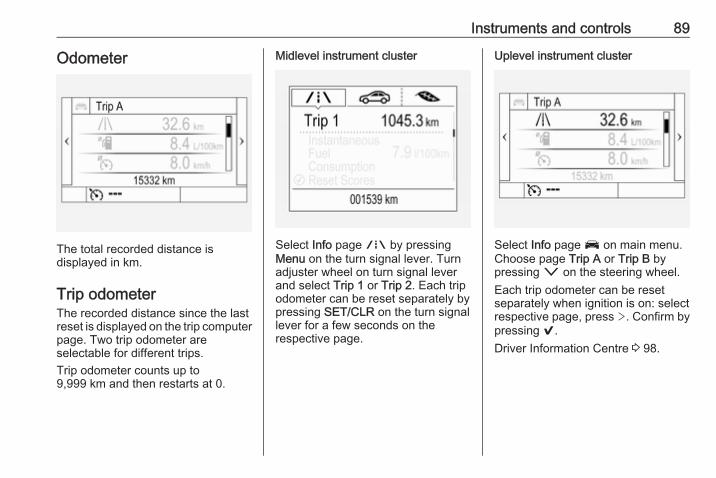
Instruments and controls 89
Odometer
The total recorded distance isdisplayed in km.
Trip odometerThe recorded distance since the lastreset is displayed on the trip computerpage. Two trip odometer areselectable for different trips.Trip odometer counts up to9,999 km and then restarts at 0.
Midlevel instrument cluster
Select Info page ; by pressingMenu on the turn signal lever. Turnadjuster wheel on turn signal leverand select Trip 1 or Trip 2. Each tripodometer can be reset separately bypressing SET/CLR on the turn signallever for a few seconds on therespective page.
Uplevel instrument cluster
Select Info page J on main menu.Choose page Trip A or Trip B bypressing o on the steering wheel.Each trip odometer can be resetseparately when ignition is on: selectrespective page, press >. Confirm bypressing 9.Driver Information Centre 3 98.

90 Instruments and controls
Tachometer
Displays the engine speed.Drive in a low engine speed range foreach gear as much as possible.
Caution
If the needle is in the red warningzone, the maximum permittedengine speed is exceeded. Engineat risk.
Fuel gauge
Displays the level in the fuel tank.The arrow indicates the vehicle sidewhere the fuel filler flap is located.Control indicator Y illuminates if thelevel in the tank is low. Refuelimmediately if it flashes.Never run the fuel tank dry.Because of the fuel remaining in thetank, the top-up quantity may be lessthan the specified fuel tank capacity.
Engine coolant temperaturegauge
Displays the coolant temperature.50 : engine operating
temperature not yetreached
centralarea
: normal operatingtemperature
130 : temperature too high

Instruments and controls 91
Caution
If engine coolant temperature istoo high, stop vehicle, switch offengine. Danger to engine. Checkcoolant level.
Service displayThe engine oil life system informswhen to change the engine oil andfilter. Based on driving conditions, theinterval at which an engine oil andfilter change will be indicated can varyconsiderably.
The remaining oil life duration menuis displayed in the Driver InformationCentre 3 98.
On Midlevel display select theSettings Menu by pressing MENU onthe turn signal lever. Turn the adjusterwheel to select the Remaining OilLife page.
On Uplevel display select Info Menuby pressing p on steering wheel.Press P to select Remaining OilLife page.Remaining oil life duration is indicatedin percentage.
ResetOn Midlevel display press SET/CLRon turn signal lever for severalseconds to reset. The ignition must beswitched on but engine not running.On Uplevel display press > onsteering wheel to open the subfolder.Select Reset and confirm by pressing

92 Instruments and controls
9 for several seconds. The ignitionmust be switched on but engine notrunning.The system must be reset every timethe engine oil is changed to allowproper functionality. Seek theassistance of a workshop.
Next serviceWhen the system has calculated thatengine oil life has been diminished,Change Engine Oil Soon appears inthe Driver Information Centre. Haveengine oil and filter changed by aworkshop within one week or500 km (whichever occurs first).Service information 3 240.
Control indicatorsThe control indicators described arenot present in all vehicles. Thedescription applies to all instrumentversions. Depending on theequipment, the position of the controlindicators may vary. When theignition is switched on, most controlindicators will illuminate briefly as afunctionality test.
The control indicator colours mean:red : danger, important reminderyellow : warning, information, faultgreen : confirmation of activationblue : confirmation of activationwhite : confirmation of activation
See all control indicators on differentinstrument clusters 3 85.
Turn signalO illuminates or flashes green.
Illuminates brieflyThe parking lights are switched on.
FlashesA turn signal or the hazard warningflashers are activated.Rapid flashing: failure of a turn signallight or associated fuse, failure of turnsignal light on trailer.Bulb replacement 3 203, Fuses3 211.Turn signals 3 124.
Seat belt reminderSeat belt reminder on front seatsX for driver's seat illuminates orflashes red in the instrument cluster.
k for front passenger seat illuminatesor flashes red in the roof console,when seat is occupied.
IlluminatesAfter the ignition has been switchedon until the seat belt has beenfastened.
FlashesAfter having started the engine for amaximum of 100 seconds until theseat belt has been fastened.

Instruments and controls 93
Seat belt status on rear seats(vehicles with Midlevel display)X illuminates or flashes white or greyin the Driver Information Centre, afterhaving started the engine.
Illuminates whiteSeat belt is unfastened.
Illuminates greySeat belt has been fastened.
Flashes white or greyFastened seat belt has beenunfastened.Fastening the seat belt 3 51.
Seat belt status on rear seats(vehicles with Uplevel display)X illuminates green or grey or flashesyellow in the Driver InformationCentre, after having started theengine.
Illuminates greySeat belt is unfastened.
Illuminates greenSeat belt has been fastened.
Flashes yellowFastened seat belt has beenunfastened.Fastening the seat belt 3 51.
Airbag and belt tensionersv illuminates red.When the ignition is switched on, thecontrol indicator illuminates forapprox. four seconds. If it does notilluminate, does not go out afterfour seconds or illuminates whilstdriving, there is a fault in the airbagsystem. Seek the assistance of aworkshop. The airbags and beltpretensioners may fail to trigger in theevent of an accident.Deployment of the belt pretensionersor airbags is indicated by continuousillumination of v.
9 Warning
Have the cause of the faultremedied immediately by aworkshop.
Belt pretensioners, airbag system3 50, 3 53.
Airbag deactivation
V illuminates yellow.The front passenger airbag isactivated.* illuminates yellow.The front passenger airbag isdeactivated.Airbag deactivation 3 57.
Charging systemp illuminates red.Illuminates when the ignition isswitched on and extinguishes shortlyafter the engine starts.

94 Instruments and controls
Illuminates when the engine isrunningStop, switch off engine. Vehiclebattery is not charging. Enginecooling may be interrupted. Thebrake servo unit may cease to beeffective. Seek the assistance of aworkshop.
Malfunction indicator lightZ illuminates or flashes yellow.Illuminates when the ignition isswitched on and extinguishes shortlyafter the engine starts.
Illuminates when the engine isrunningFault in the emission control system.The permitted emission limits may beexceeded. Seek the assistance of aworkshop immediately.
Flashes when the engine isrunningFault that could lead to catalyticconverter damage. Ease up on theaccelerator until the flashing stops.Seek the assistance of a workshopimmediately.
Brake and clutch systemR illuminates red.The brake and clutch fluid level is toolow , when manual parking brake isnot applied 3 200.
9 Warning
Stop. Do not continue yourjourney. Consult a workshop.
Illuminates when the manual parkingbrake is applied and ignition isswitched on 3 158.
Electric parking brakem illuminates or flashes red.
IlluminatesElectric parking brake is applied3 158.
FlashesElectric parking brake is not fullyapplied or released. Depress thebrake pedal and attempt to reset thesystem by first releasing thenapplying the electric parking brake. Ifm remains flashing, do not drive andseek the assistance of a workshop.
Electric parking brake faultj illuminates or flashes yellow.
IlluminatesElectric parking brake is operatingwith degraded performance 3 158.
FlashesElectric parking brake is in servicemode. Stop vehicle, apply andrelease the electric parking brake toreset.

Instruments and controls 95
9 Warning
Have the cause of the faultremedied immediately by aworkshop.
Antilock brake system(ABS)u illuminates yellow.Illuminates for a few seconds after theignition is switched on. The system isready for operation when the controlindicator extinguishes.If the control indicator does not go outafter a few seconds, or if it illuminateswhile driving, there is a fault in theABS. The brake system remainsoperational but without ABSregulation.Antilock brake system 3 157.
Gear shiftingR or S with the number of the nexthigher or lower gear is indicated,when up- or down-shifting isrecommended.
Following distanceE indicates the following distancesetting of the alert timing sensitivityfor the forward collision alert usingfilled distance bars.Forward collision alert 3 167.
Lane keep assista illuminates green or yellow, orflashes yellow.
Illuminates greenThe system is switched on and readyto operate.
Illuminates yellowThe system approaches a detectedlane marking without using the turnsignal in that direction.
Flashes yellowThe system recognizes that the laneis departed significantly.Lane keep assist 3 186
Electronic Stability Controloffn illuminates yellow.The system is deactivated.
Electronic Stability Controland Traction Control systemb illuminates or flashes yellow.
IlluminatesA fault in the system is present.Continued driving is possible. Drivingstability, however, may deterioratedepending on road surfaceconditions.Have the cause of the fault remediedby a workshop.
FlashesThe system is actively engaged.Engine output may be reduced andthe vehicle may be brakedautomatically to a small degree.Electronic Stability Control 3 161,Traction Control system 3 160.

96 Instruments and controls
Traction Control system offk illuminates yellow.The system is deactivated.
Preheating! illuminates yellow.Preheating of Diesel engine isactivated. Only activates whenoutside temperature is low. Start theengine when control indicatorextinguishes.
Tyre pressure monitoringsystemw illuminates or flashes yellow.
IlluminatesTyre pressure loss. Stop immediatelyand check tyre pressure.
FlashesFault in system or tyre withoutpressure sensor mounted (e.g. sparewheel). After 60 to 90 seconds thecontrol indicator illuminatescontinuously. Consult a workshop.
Engine oil pressureI illuminates red.Illuminates when the ignition isswitched on and extinguishes shortlyafter the engine starts.
Illuminates when the engine isrunning
Caution
Engine lubrication may beinterrupted. This may result indamage to the engine and/orlocking of the drive wheels.
1. Depress clutch.2. Select neutral gear, set selector
lever to N.3. Move out of the flow of traffic as
quickly as possible withoutimpeding other vehicles.
4. Switch off ignition.
9 Warning
When the engine is off,considerably more force is neededto brake and steer. During anAutostop the brake servo unit willstill be operational.Do not remove key until vehicle isstationary, otherwise the steeringwheel lock could engageunexpectedly.
Check oil level before seekingassistance of a workshop 3 198.
Low fuelY illuminates or flashes yellow.
IlluminatesLevel in fuel tank is too low.
FlashesFuel used up. Refuel immediately.Never run the tank dry.Refuelling 3 189.Catalytic converter 3 150.

Instruments and controls 97
Bleeding the diesel fuel system3 202.
Immobiliserd flashes yellow.Fault in the immobiliser system. Theengine cannot be started.
Exterior light8 illuminates green.The exterior lights are on 3 118.
High beamC illuminates blue.Illuminated when high beam is on orduring headlight flash 3 119.
High beam assistf illuminates green.The high beam assist is activated,see LED headlights 3 120.
LED headlightsf illuminates or flashes yellow.
IlluminatesFault in the system.Seek the assistance of a workshop.
FlashesSystem is switched to symmetricallow beam.Control indicator f flashes for approx.four seconds after the ignition isswitched on as a reminder forsymmetrical headlight 3 120.
Fog light> illuminates green.The front fog lights are on 3 124.
Rear fog lightr illuminates yellow.The rear fog light is on 3 125.
Cruise controlm illuminates white or green.
Illuminates whiteThe system is on.
Illuminates greenCruise control is active. Set speed isindicated in the Driver InformationCentre.Cruise control 3 163.
Vehicle detected aheadA illuminates green or yellow.
Illuminates greenA vehicle ahead is detected in thesame lane.
Illuminates yellowThe distance to a preceding movingvehicle gets too small or whenapproaching another vehicle toorapidly.Forward collision alert 3 167.
Speed limiterL illuminates white or green.
Illuminates whiteThe system is on.

98 Instruments and controls
Illuminates greenSpeed limiter is active. Set speed isindicated near L symbol.Speed limiter 3 165.
Traffic sign assistantL displays detected traffic signs ascontrol indicator.Traffic sign assistant 3 182.
Door openh illuminates red.A door or the tailgate is open.
Information displaysDriver Information CentreThe Driver Information Centre islocated in the instrument cluster.Depending on the version and theinstrument cluster, the DriverInformation Centre is available asMidlevel display or Uplevel display.Driver Information Centre indicatesdepending on the equipment:● overall and trip odometer● vehicle information● trip/fuel information● economic information● vehicle and warning messages● audio and infotainment
information● phone information● navigation information● vehicle settings
Midlevel display
The menu pages of the Midleveldisplay are selected by pressingMENU on the turn signal lever. Mainmenu symbols are indicated in the topline of the display:● W Info Menu● ? Options Menu● @ ECO Information Menu
Some of the displayed functions differbetween vehicle driving and standstilland some functions are only activewhen the vehicle is driving.Vehicle personalisation 3 107.Memorised settings 3 24.

Instruments and controls 99
Selecting menus and functionsThe menus and functions can beselected via the buttons on the turnsignal lever.
Press MENU to switch between themain menus or to return from asubmenu to the next higher menulevel.Turn the adjuster wheel to select asubpage of the main menu or to set anumeric value.Press SET/CLR to select and confirma function.
Vehicle and service messages arepopped up in the Driver InformationCentre if required. Confirm messagesby pressing SET/CLR. Vehiclemessages 3 105.
Uplevel display
Menu pages are indicated bypressing p on the steering wheel.Press Q or P to select a menu,press 9 to confirm. Selectable menupages are:● Info● Audio● Phone
● Navigation● Options
Some of the displayed functions differbetween vehicle driving and standstilland some functions are only activewhen the vehicle is driving.Vehicle personalisation 3 107.Memorised settings 3 24.
Selecting menus and functionsThe menus and functions can beselected via the buttons on the rightside in the steering wheel.
Press p to open main menu page.Select a main menu page with Q orP.

100 Instruments and controls
Confirm a main menu page with 9.Once a main menu page is selected,press Q or P to select subpages.Press q to open a next folder of theselected subpage.Press Q or P to select functions orto set a numeric value, if required.Press 9 to select and confirm afunction.Once a main menu page is selected,this selection remains stored untilanother main menu page is selected.Subpages are changed by pressingP or Q.Vehicle and service messages arepopped-up in the Driver InformationCentre if required. Confirm messagesby pressing 9. Vehicle messages3 105.
Info MenuThe following list contains all possibleInfo Menu pages. Some may not beavailable for your particular vehicle.Depending on the display somefunctions are symbolised.
Turn the adjuster wheel or press Qor P to select a page:● trip odometer 1 or A
average fuel consumptionaverage speed
● trip odometer 2 or Baverage fuel consumptionaverage vehicle speed
● digital speed● fuel range● instantaneous fuel consumption● remaining oil life● tyre pressure● timer● traffic sign assistant● following distance● top consumers● economy trend● Eco index● blank page
On Midlevel display, the pagesRemaining Oil Life, Tyre Pressure,Traffic Sign Assistant and Following
Distance are displayed in the OptionsMenu ?. Select by pressingMENU.On Midlevel display, the pages TopConsumers, Economy Trend and Ecoindex are displayed in the ECOInformation Menu@. Select bypressing MENU.
Trip odometer 1/A and 2/BTrip odometer displays the currentdistance since a certain reset.Trip odometer counts up to a distanceof 9,999 km then restarts at 0.To reset on Midlevel display, pressSET/CLR for a few seconds, onUplevel display, press > and confirmwith 9.The information of trip odometer page1/A and 2/B can be reset separatelyfor odometer, average consumptionand average speed while therespective display is active.
Average Fuel ConsumptionDisplay of average consumption. Themeasurement can be reset at anytime and starts with a default value.

Instruments and controls 101
To reset on Midlevel display, pressSET/CLR for a few seconds, onUplevel display, press > and confirmwith 9.
Average speedDisplay of average speed. Themeasurement can be reset at anytime.To reset on Midlevel display, pressSET/CLR for a few seconds, onUplevel display, press > and confirmwith 9.
Digital speedDigital display of the instantaneousspeed.
Fuel rangeRange is calculated from current fuellevel and current consumption. Thedisplay shows average values.After refuelling, the range is updatedautomatically after a brief delay.When the level in the fuel tank is low,a message appears on the displayand the control indicator Y in the fuelgauge illuminates.
When the fuel tank has to be refuelledimmediately, a warning messageappears and remains on the display.Additionally, the control indicator Y inthe fuel gauge flashes 3 96.
Instantaneous Fuel ConsumptionDisplay of the instantaneousconsumption.
Remaining Oil LifeIndicates an estimate of the oil'suseful life. The number in percentagemeans the remainder of current oil life3 91.
Tyre PressureChecks tyre pressure of all wheelsduring driving 3 220.
TimerTo start and stop, press 9. To reset,press > and confirm reset.
Traffic sign assistantDisplays the detected traffic signs forthe current route section 3 182.
Following DistanceDisplays the distance in seconds to apreceding moving vehicle 3 169. IfAdaptive cruise control is active thispage shows the following distancesetting instead.
Top ConsumersList of top comfort consumerscurrently switched on is displayed indescending order. Fuel savingpotential is indicated. A switched-offconsumer disappears from the listand the consumption value will beupdated.During sporadic driving conditions,the engine will activate the rearwindow defog automatically toincrease the engine load. In thisevent, the rear window defog isindicated as one of the topconsumers, without activation by thedriver.
Economy TrendDisplays the average consumptiondevelopment over a distance of50 km. Filled segments display the

102 Instruments and controls
consumption in 5 km steps and showsthe effect of topography or drivingbehaviour on fuel consumption.
Economy indexThe current fuel consumption isindicated on an economic scale. Foreconomical driving adapt the drivingstyle to keep the indicator within theEco area. Indicator outside the Ecoarea means higher fuel consumption.
Blank pageShows a blank page without anyinformation.
Audio MenuAudio menu enables browsing formusic, selecting from favourites orchanging the audio source.See Infotainment manual.
Phone MenuPhone menu enables managing andperforming of phone calls, scrollingthrough contacts or operatinghandsfree phoning.See Infotainment manual.
Navigation MenuNavigation menu enables routeguidance.See Infotainment manual.
Options MenuThe following list contains all possibleOptions Menu pages. Some may notbe available for your particularvehicle. Depending on the displaysome functions are symbolised.Turn the adjuster wheel or press Qor P to select a page and follow theinstructions given in the submenus:● units● info pages● speed warning● tyre loading● software information
UnitsPress SET/CLR or > while units isdisplayed. Select imperial or metricunits by turning adjuster wheel orpressing P. Confirm by pressingSET/CLR or 9.
Info pagesPress > while Info pages is displayed.A list of all items in the Info Menu isdisplayed. Select the functions to bedisplayed in the Info page by pressing9. Selected pages have a 9 in acheckbox. Non viewable functionshave a blank checkbox. See InfoMenu above.
Speed warning
The speed warning function alarmswhen a set speed is exceeded.To set the speed warning, pressSET/CLR or > while the page isdisplayed. Turn the adjuster wheel orpress Q or P to select and adjust the

Instruments and controls 103
value. Press SET/CLR or 9 to set thespeed. Once the speed is set, thisfeature can be turned off by pressingSET/CLR or 9 while viewing thispage. If the selected speed limit isexceeded, a pop-up warning isdisplayed with a chime.
Tyre LoadThe tyre pressure category accordingto the actually inflated tyre pressurecan be selected 3 220.
Software informationDisplays the open source softwareinformation.
Valet modeSome functions of the DriverInformation Centre and the Info-Display can be limited for somedrivers.Activation or deactivation of valetmode can be set in the menuSettings in the vehicle personalisationmenu.Vehicle personalisation 3 107.For more information seeInfotainment manual.
Info displayThe Info-Display is located in theinstrument panel near the instrumentcluster.Depending on the vehicleconfiguration the vehicle has a● Graphic-Info-Display
or● 7'' Colour-Info-Display with
touch-screen functionalityor
● 8'' Colour-Info-Displaytouch-screen functionality
The Info displays can indicate:● time 3 80● outside temperature 3 80● date 3 80● Infotainment system, see
description in the Infotainmentmanual
● indication of rear view camera3 180
● indication of parking assistinstructions 3 171
● navigation, see description in theInfotainment manual
● system messages● settings for vehicle
personalisation 3 107
Graphic-Info-Display
Press X to switch on the display.Press MENU to select main menupage.Turn MENU to select a menu page.Press MENU to confirm a selection.Press BACK to exit a menu withoutchanging a setting.

104 Instruments and controls
7'' Colour-Info-Display
Selecting menus and settingsMenus and settings are accessed viathe display.
Press X to switch on the display.Press ; to display the homepage.Tap required menu display icon withthe finger.Tap a respective icon to confirm aselection.Tap 9 to return to the next highermenu level.Press ; to return to the homepage.
For further information, seeInfotainment manual.Vehicle personalisation 3 107.
8'' Colour-Info-Display
Selecting menus and settingsThere are three options to operate thedisplay:● via buttons below the display● directly per touchscreen
operation by the finger● via speech recognition
Button operation
Press X to switch on the display.
Press ; to display the homepage.Turn MENU to select a menu displayicon or a function or to scroll asubmenu list.Press MENU to confirm a selection.Press BACK to exit a menu withoutchanging a setting.Press ; to return to the homepage.For further information, seeInfotainment manual.Touchscreen operationDisplay must be switched on bypressing X. Press ; to selecthomepage.Tap required menu display icon or afunction with the finger.Scroll a longer submenu list with thefinger up or down.Confirm a required function orselection by tapping.Tap q on the display to exit a menuwithout changing a setting.Press ; to return to the homepage.For further information, seeInfotainment manual.

Instruments and controls 105
Speech recognitionDescription see Infotainment manual.Vehicle personalisation 3 107.
Valet modeSome functions of the DriverInformation Centre and the Info-Display can be limited for somedrivers.Activation or deactivation of valetmode can be set in the menuSettings in the vehicle personalisationmenu.Vehicle personalisation 3 107.For more information seeInfotainment manual.
Vehicle messagesMessages are indicated in the DriverInformation Centre, in some casestogether with a warning and signalchime.
On Midlevel display press SET/CLRon the turn signal lever to confirm amessage.
On Uplevel display press 9 on thesteering wheel to confirm a message.
Vehicle and service messagesThe vehicle messages are displayedas text. Follow the instructions givenin the messages.The system displays messagesregarding the following topics:● service messages● fluid levels● anti-theft alarm system● brakes● drive systems● ride control systems

106 Instruments and controls
● driver assistance systems● cruise control● speed limiter● forward collision alert● collision imminent braking
system● parking assist systems● lighting, bulb replacement● LED headlights● wiper/washer system● doors, windows● side blind spot alert● traffic sign assistant● lane keep assist● load compartment, tailgate● radio remote control● electronic key system● keyless starting● seat belts● airbag systems● engine and transmission● tyre pressure● diesel particle filter
● vehicle battery status● stop-start system
Messages in theColour-Info-DisplaySome important messages mayappear additionally in theColour-Info-Display. Press themultifunction knob to confirm amessage. Some messages only pop-up for a few seconds.
Warning chimesWhen starting the engine or whilstdrivingOnly one warning chime will sound ata time.The warning chime regarding notfastened seat belts has priority overany other warning chime.● If seat belt is not fastened.● If a door or the tailgate is not fully
closed when starting off.● If a certain speed is exceeded
with parking brake applied.
● If approaching a vehicle aheadtoo closely.
● If a programmed speed or speedlimit is exceeded.
● If a warning message appears inthe Driver Information Centre.
● If the electronic key is not in thepassenger compartment.
● If the parking assist detects anobject.
● If an unintended lane changeoccurs.
● If the diesel particle filter hasreached the maximum fillinglevel.
When the vehicle is parked and/orthe driver's door is opened● With exterior lights on.
During an Autostop● If the driver's door is opened.● If any condition for an autostart is
not fulfilled.

Instruments and controls 107
Battery voltageWhen the vehicle battery voltage isrunning low, a warning message willappear in the Driver InformationCentre.1. Switch off any electrical
consumers which are not requiredfor a safe drive, e.g. seat heating,heated rear window or other mainconsumers.
2. Charge the vehicle battery bydriving continuously for a while orby using a charging device.
The warning message will disappearafter the engine has been startedtwice without a voltage drop.If the vehicle battery cannot berecharged, have the cause of the faultremedied by a workshop.
Vehicle personalisationThe vehicle's behaviour can bepersonalised by changing the settingsin the Info-Display.Some of the personal settings fordifferent drivers can be memorisedindividually for each vehicle key.Memorised settings 3 24.Depending on vehicle equipment andcountry-specific regulations some ofthe functions described below maynot be available.Some functions are only displayed oractive when the engine is running.
Personal settingsGraphic-Info-DisplayPress MENU to open the respectivemenu.Select Settings, scroll through the listand select Vehicle Settings
In the corresponding submenus thefollowing settings can be changed:
Vehicle Settings● Climate and Air Quality
Auto Fan Max Speed: Modifiesthe level of the cabin airflow of theclimate control in automaticmode.Climate Control Mode: Controlsthe state of the coolingcompressor when the vehicle isstarted. Last setting(recommended) or at vehiclestart is either always on or alwaysoff.

108 Instruments and controls
Temperature Zone at Start:Change between single zone ordual zone temperature setting.Auto Cooled Seats:Automatically activates the seatventilation.Auto Heated Seats:Automatically activates the seatheating.Auto Demist: Supportswindscreen dehumidification byautomatically selecting thenecessary settings andautomatic air conditioning mode.Auto Rear Demist: Automaticallyactivates heated rear window.
● Park Assist / Collision DetectionForward Collision Alert: Activatesor deactivates forward collisionalert.Collision Preparation: Activatesor deactivates the automaticbrake functionality of the vehiclein the event of imminent collisiondanger. The following isselectable: the system will takeover brake control, warn by
chimes only or is deactivatedcompletely.Park Assist: Activates ordeactivates the ultrasonicparking assist. Activation isselectable with or withoutattached trailer coupling.Side Blind Zone Alert: Activatesor deactivates side blind zonealert.Lane Change Alert: Activates ordeactivates lane keep assist.
● Comfort SettingsAuto Memory Recall: Changesthe settings to the recall ofmemorised settings for powerseat adjustment and exteriormirrors.Easy Exit Driver Seat: Activatesor deactivates easy exit functionof the power seat.Chime Volume: Changes thevolume of warning chimes.Auto Mirror Tilt in Reverse:Activates or deactivates theparking assist function of theexterior mirror.
Comf. Closing Mirror Fold:Activates or deactivates foldingof the exterior mirrors with theremote control.Personalisation by Driver:Activates or deactivates thepersonalisation function.Rain Sense Wipers: Activates ordeactivates automatic wipingwith rain sensor.Rear Auto Wipe in Reverse:Activates or deactivatesautomatic switching on of therear window wiper when reversegear is engaged.
● Exterior Ambient LightingExterior lighting by unlocking:Activates or deactivates the entrylighting.Duration upon exit of vehicle:Activates or deactivates andchanges the duration of exitlighting.Left or Right Hand Traffic:Changes between lighting for leftor right-hand traffic.

Instruments and controls 109
Adaptive Forward Lighting:Changes the settings of thefunctions of the LED headlights.Daytime Tail Lamps: Activates ordeactivates the tail lights incombination with daytimerunning lights.
● Power Door LocksStop door lock if door open:Activates or deactivates the doorlocking function while a door isopen.Auto Door Lock: Activates ordeactivates the automatic doorlocking function after switchingon ignition.Auto Door Unlock: Changes theconfiguration to unlock only thedriver's door or the whole vehicleafter switching off ignition.Delayed Door Lock: Activates ordeactivates the delayed doorlocking function. This featuredelays the actual locking of thedoors until all doors are closed.
● Remote Lock, Unlock, and StartRemote Unlock Feedback:Activates or deactivates the
hazard warning flasher feedbackwhilst unlocking.Remote Lock Feedback:Changes what kind of feedbackis given when locking the vehicle.Remote Door Unlock: Changesthe configuration to unlock onlythe driver's door or the wholevehicle whilst unlocking.Auto Relock Doors: Activates ordeactivates the automatic relockfunction after unlocking withoutopening the vehicle.Remote Window Operation:Activates or deactivates theoperation of power windows withremote control.Passive Door Lock: Activates ordeactivates the passive lockingfunction. This feature locks thevehicle automatically afterseveral seconds if all doors havebeen closed and an electronickey has been removed from thevehicle.Remote Left in Vehicle Alarm:Activates or deactivates thewarning chime when the
electronic key remains in thevehicle.
● Restore Factory Settings:Resets all settings to the defaultsettings.
● Valet Mode:See Infotainment manual.
Personal settings7" Colour-Info-DisplayPress ; then select the Settingsscreen button.
In the corresponding submenus thefollowing settings can be changed:

110 Instruments and controls
Settings● Climate & Air Quality
Auto Fan Max Speed: Modifiesthe level of the cabin airflow of theclimate control in automaticmode.Air Conditioning Mode: Controlsthe state of the coolingcompressor when the vehicle isstarted. Last setting(recommended) or at vehiclestart is either always on or alwaysoff.Auto Compartment Zone Temp:Change between single zone ordual zone temperature setting.Auto Cooled Seats:Automatically activates the seatventilation.Auto Heated Seats:Automatically activates the seatheating.Auto Defog: Supportswindscreen dehumidification byautomatically selecting thenecessary settings andautomatic air conditioning mode.
Auto Rear Defog: Automaticallyactivates heated rear window.
● Collision / Detection SystemsForward Collision Alert :Activates or deactivates forwardcollision alert.Auto Collision Preparation:Activates or deactivates theautomatic brake functionality ofthe vehicle in the event ofimminent collision danger. Thefollowing is selectable: thesystem will take over brakecontrol, warn by chimes only or isdeactivated completely.Forward Collision System:Changes the settings of forwardcollision alert.Park Assist: Activates ordeactivates the ultrasonicparking assist. Activation isselectable with or withoutattached trailer coupling.Side Blind Zone Alert: Activatesor deactivates side blind zonealert.Lane Change Alert : Activates ordeactivates lane keep assist.
● Comfort and ConvenienceAuto Memory Recall : Changesthe settings to the recall ofmemorised settings for powerseat adjustment and exteriormirrors.Easy Exit Driver Seat: Activatesor deactivates easy exit functionof the power seat.Chime Volume: Changes thevolume of warning chimes.Reverse Tilt Mirror: Activates ordeactivates the parking assistfunction of the exterior mirror.Auto Mirror Folding: Activates ordeactivates folding of the exteriormirrors with the remote control.Personalization By Driver:Activates or deactivates thepersonalisation function.Rain Sense Wipers: Activates ordeactivates automatic wipingwith rain sensor.Auto Wipe in Reverse Gear:Activates or deactivatesautomatic switching on of therear window wiper when reversegear is engaged.

Instruments and controls 111
Extended Hill Start Assist:Changes the settings of hill startassist.
● LightingVehicle Locator Lights: Activatesor deactivates the entry lighting.Exit Lighting: Activates ordeactivates and changes theduration of exit lighting.Left or Right Hand Traffic :Changes between lighting for leftor right-hand traffic.Adaptive Forward Lighting :Changes the settings of thefunctions of the LED headlights.Daytime Tail Lights : Activates ordeactivates the tail lights incombination with daytimerunning lights.
● Power Door LocksUnlocked Door Anti Lock Out:Activates or deactivates the doorlocking function while a door isopen.Auto Door Lock: Activates ordeactivates the automatic door
locking function after switchingon ignition.Auto Door Unlock: Changes theconfiguration to unlock only thedriver's door or the whole vehicleafter switching off ignition.Delayed Door Lock: Activates ordeactivates the delayed doorlocking function. This featuredelays the actual locking of thedoors until all doors are closed.
● Remote Lock, Unlock, StartRemote Unlock Light Feedback:Activates or deactivates thehazard warning flasher feedbackwhilst unlocking.Remote Lock Feedback:Changes what kind of feedbackis given when locking the vehicle.Remote Door Unlock: Changesthe configuration to unlock onlythe driver's door or the wholevehicle whilst unlocking.Relock Remotely UnlockedDoors: Activates or deactivatesthe automatic relock functionafter unlocking without openingthe vehicle.
Remote Window Operation:Activates or deactivates theoperation of power windows withremote control.Passive Door Lock : Activates ordeactivates the passive lockingfunction. This feature locks thevehicle automatically afterseveral seconds if all doors havebeen closed and an electronickey has been removed from thevehicle.Remote Left in Vehicle Alert:Activates or deactivates thewarning chime when theelectronic key remains in thevehicle.
Personal settings8" Colour-Info-DisplayPress ; then select the SETTINGSicon.
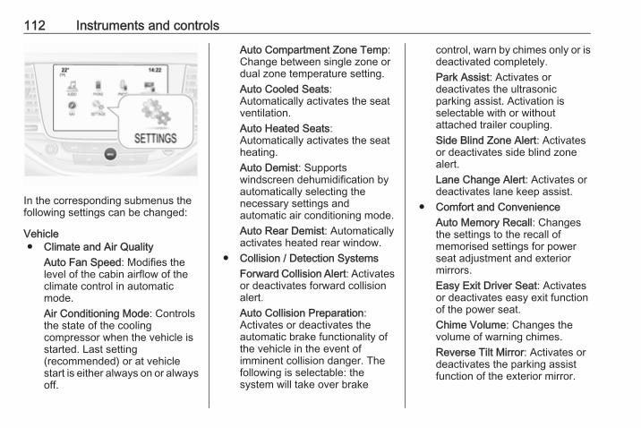
112 Instruments and controls
In the corresponding submenus thefollowing settings can be changed:
Vehicle● Climate and Air Quality
Auto Fan Speed: Modifies thelevel of the cabin airflow of theclimate control in automaticmode.Air Conditioning Mode: Controlsthe state of the coolingcompressor when the vehicle isstarted. Last setting(recommended) or at vehiclestart is either always on or alwaysoff.
Auto Compartment Zone Temp:Change between single zone ordual zone temperature setting.Auto Cooled Seats:Automatically activates the seatventilation.Auto Heated Seats:Automatically activates the seatheating.Auto Demist: Supportswindscreen dehumidification byautomatically selecting thenecessary settings andautomatic air conditioning mode.Auto Rear Demist: Automaticallyactivates heated rear window.
● Collision / Detection SystemsForward Collision Alert: Activatesor deactivates forward collisionalert.Auto Collision Preparation:Activates or deactivates theautomatic brake functionality ofthe vehicle in the event ofimminent collision danger. Thefollowing is selectable: thesystem will take over brake
control, warn by chimes only or isdeactivated completely.Park Assist: Activates ordeactivates the ultrasonicparking assist. Activation isselectable with or withoutattached trailer coupling.Side Blind Zone Alert: Activatesor deactivates side blind zonealert.Lane Change Alert: Activates ordeactivates lane keep assist.
● Comfort and ConvenienceAuto Memory Recall: Changesthe settings to the recall ofmemorised settings for powerseat adjustment and exteriormirrors.Easy Exit Driver Seat: Activatesor deactivates easy exit functionof the power seat.Chime Volume: Changes thevolume of warning chimes.Reverse Tilt Mirror: Activates ordeactivates the parking assistfunction of the exterior mirror.

Instruments and controls 113
Auto Mirror Folding: Activates ordeactivates folding of the exteriormirrors with the remote control.Personalisation by Driver:Activates or deactivates thepersonalisation function.Rainsense Wipers: Activates ordeactivates automatic wipingwith rain sensor.Auto Wipe in Reverse Gear:Activates or deactivatesautomatic switching on of therear window wiper when reversegear is engaged.Extended Hill-Start Assist:Changes the settings of hill startassist.
● LightingVehicle Locator Lights: Activatesor deactivates the entry lighting.Exit Lighting: Activates ordeactivates and changes theduration of exit lighting.Left or Right Hand Traffic:Changes between lighting for leftor right-hand traffic.
Adaptive Forward Lighting:Changes the settings of thefunctions of the LED headlights.Daytime Tail Lights: Activates ordeactivates the tail lights incombination with daytimerunning lights.
● Power Door LocksUnlocked Door Anti-Lockout:Activates or deactivates the doorlocking function while a door isopen.Auto Door Lock: Activates ordeactivates the automatic doorlocking function after switchingon ignition.Auto Door Unlock: Changes theconfiguration to unlock only thedriver's door or the whole vehicleafter switching off ignition.Delayed Door Lock: Activates ordeactivates the delayed doorlocking function. This featuredelays the actual locking of thedoors until all doors are closed.
● Remote Lock, Unlock, StartRemote Unlock Light Feedback:Activates or deactivates the
hazard warning flasher feedbackwhilst unlocking.Remote Lock Feedback:Changes what kind of feedbackis given when locking the vehicle.Remote Door Unlock: Changesthe configuration to unlock onlythe driver's door or the wholevehicle whilst unlocking.Relock Remote Unlocked Doors:Activates or deactivates theautomatic relock function afterunlocking without opening thevehicle.Remote Window Operation:Activates or deactivates theoperation of power windows withremote control.Passive Door Lock: Activates ordeactivates the passive lockingfunction. This feature locks thevehicle automatically afterseveral seconds if all doors havebeen closed and an electronickey has been removed from thevehicle.Remote Left in Vehicle Alert:Activates or deactivates the

114 Instruments and controls
warning chime when theelectronic key remains in thevehicle.
OnStar® systemOnStar is a personal connectivity andmobility assistant with integratedWi-Fi hotspot. The OnStar service isavailable 24 hours a day, seven daysa week.NoteOnStar is not available for allmarkets. For further information,contact your workshop.NoteIn order to be available andoperational, OnStar needs a validOnStar subscription, functioningvehicle electrics, mobile service andGPS satellite link.
To activate the OnStar services andset up an account, press Z and speakwith an OnStar advisor.Depending on the equipment of thevehicle, the following services areavailable:● OnStar emergency services and
support in the case of a vehiclebreakdown
● Wi-Fi hotspot
● OnStar smartphone application● OnStar remote services, e.g.
location of the vehicle, activationof horn and lights, control ofcentral locking system
● Stolen vehicle assistance● Vehicle health check● Destination downloadNoteAll functions requiring dataconnection to the vehicle are nolonger available if the vehicle ignitionhas not been turned on for ten days.
OnStar buttons

Instruments and controls 115
Privacy buttonPress and hold j until an audiomessage is heard to activate ordeactivate the transmission of thevehicle location.Press j to answer a call or to end acall to an OnStar advisor.Press j to access the Wi-Fi settings.
OnStar buttonPress Z to establish a connection toan OnStar advisor.
SOS buttonPress [ to establish a priorityemergency connection to a speciallytrained emergency advisor.
Status lightGreen: The system is ready.Green flashing: The system is on acall.Red: A problem arose.Off: System is off.Red / green flashing for a short periodof time: Transmission of the vehiclelocation has been deactivated.
OnStar services
OnStar emergency servicesOnStar emergency provides a servicewith specially trained emergencyadvisors for contact, assistance andinformation during an emergency.In the case of an emergency situationincluding vehicle breakdown, a flattyre or empty fuel tank, press [ andtalk to the advisor. The advisor thencontacts emergency or assistanceservice providers and directs them toyour vehicle.In the case of an accident withactivation of airbags or belttensioners, an automatic emergencycall is established. The advisor isimmediately connected to yourvehicle to see whether help isneeded.
OnStar Wi-Fi hotspotThe Wi-Fi hotspot of the vehicleprovides internet connectivity throughthe 4G/LTE mobile network.NoteThe Wi-Fi hotspot functionality is notavailable for all markets.
Up to seven devices may beconnected.To connect a mobile device with theOnStar Wi-Fi hotspot:1. Press j and then select Wi-Fi
settings on the Info-Display. Thesettings displayed include the Wi-Fi hotspot name (SSID),password and connection type.
2. Start a Wi-Fi network search onyour mobile device.
3. Select your vehicle hotspot(SSID) when listed.
4. When prompted, enter thepassword on your mobile device.
NoteTo change the SSID or password,select Z and talk to an OnStaradvisor or logon to your account.
To switch off the Wi-Fi hotspotfunctionality, press Z to call anOnStar advisor.
Smartphone appWith the myOpel smartphone app,some vehicle functions can beoperated via a smartphone.

116 Instruments and controls
The following functions are available:● Lock or unlock doors.● Honk horn or flash lights.● Check fuel level, engine oil life
and tyre pressure (only with tyrepressure monitoring system).
● Send navigation destination tothe vehicle, if equipped with abuilt-in navigation system.
● Locate vehicle on a map.● Manage Wi-Fi settings.
To operate these functions, downloadthe app from the respective app store.
Remote serviceIf desired, use any phone to call anOnStar advisor, who can remotelyoperate specific vehicle functions.Find the respective OnStar phonenumber on our country-specificwebsite.The following functions are available:● Lock or unlock doors.● Provide information on the
vehicle location.● Honk horn or flash lights.
Stolen vehicle assistanceIf a vehicle is stolen, the OnStarstolen vehicle assistance service canprovide support in locating andrecovering the vehicle.Theft alertWhen the anti-theft alarm system istriggered, a notification is sent toOnStar. You are then informed aboutthis event by text message or email.If required, report the theft to theauthorities and request OnStar stolenvehicle assistance. Use any phone tocall an OnStar advisor. Find therespective OnStar phone number onour country-specific website.Remote ignition blockBy sending remote signals, OnStarcan block the ignition cyclepreventing the vehicle from restartingonce it has been turned off.
On-demand diagnosticsAt any time e.g. if the vehicle displaysa service message, press Z tocontact an OnStar advisor and ask tocomplete a real-time diagnostic check
to directly determine the issue.Depending on the results, the advisorwill provide further support.
Monthly vehicle diagnosticsThe vehicle automatically transmitsdiagnostic data to OnStar whichsends a monthly email report to youand your preferred workshop.NoteThe workshop notification functioncan be disabled in your account.
The report contains the status of keyoperating systems of the vehicle likeengine, transmission, airbags,antilock brakes, and other majorsystems. It also provides informationon possible maintenance items andtyre pressure (only with tyre pressuremonitoring system).To look at the information in greaterdetail, select the link within the emailand log into your account.
Destination downloadA desired destination can be directlydownloaded to the navigation system.

Instruments and controls 117
Press Z to call an OnStar advisor anddescribe the destination or point ofinterest.The OnStar advisor can look up anyaddress or point of interest anddirectly download the destination tothe built-in navigation system.
OnStar settings
OnStar PINTo have full access to all OnStarservices, a four-digit PIN is required.The PIN has to be personalised whenfirst talking to an OnStar advisor.To change the PIN, press Z to call anOnStar advisor.
Account dataAn OnStar subscriber has anaccount, where all the data is stored.To request a change of the accountinformation, press Z and talk to anOnStar advisor or logon to youraccount.If the OnStar service is used onanother vehicle, press Z and requestthat the account be transferred to thenew vehicle.
NoteIn any case, if the vehicle is disposedof, sold or otherwise transferred,immediately inform OnStar aboutthe changes and terminate theOnStar service on this vehicle.
Vehicle locationThe vehicle location is transmitted toOnStar when service is requested ortriggered. A message on the Info-Display informs about thistransmission.To activate or deactivate thetransmission of the vehicle location,press and hold j until an audiomessage is heard.The deactivation is indicated by thestatus light flashing red and green fora short period of time and each timethe vehicle is started.NoteIf the transmission of the vehiclelocation is deactivated, someservices are no longer available.NoteThe vehicle location always remainsaccessible to OnStar in the case ofan emergency.
Find the privacy policy in youraccount.
Software updatesOnStar may remotely carry outsoftware updates without furthernotice or consent. These updates areto enhance or maintain safety andsecurity or the operation of thevehicle.These updates may concern privacyissues. Find the privacy policy in youraccount.

118 Lighting
Lighting
Exterior lighting .......................... 118Light switch .............................. 118Automatic light control ............. 119High beam ............................... 119Headlight flash ......................... 119Headlight range adjustment .... 119Headlights when drivingabroad .................................... 120
Daytime running lights ............. 120LED headlights ........................ 120Hazard warning flashers .......... 123Turn and lane-change signals . 124Front fog lights ......................... 124Rear fog light ........................... 125Parking lights ........................... 125Reversing lights ....................... 125Misted light covers ................... 125
Interior lighting ........................... 126Instrument panel illuminationcontrol ..................................... 126
Interior lights ............................ 126Reading lights .......................... 126Sunvisor lights ......................... 127
Lighting features ........................ 127Centre console lighting ............ 127
Entry lighting ............................ 127Exit lighting .............................. 127Battery discharge protection .... 128
Exterior lightingLight switch
Turn light switch:AUTO : automatic light control
switches automaticallybetween daytime runninglight and headlight
8 : sidelights9 : headlights
When switching on the ignition,automatic light control is active.Control indicator 8 3 97.

Lighting 119
Tail lightsTail lights are illuminated togetherwith low/high beam and sidelights.
Automatic light control
When the automatic light controlfunction is switched on and theengine is running, the systemswitches between daytime runninglights and headlights automaticallydepending on the external lightingconditions and information given bythe rain sensor system.Daytime running light 3 120.
Automatic headlight activationDuring poor lighting conditionsheadlights are switched on.Additionally, headlights are switchedon if the windscreen wipers havebeen activated for several wipes.LED headlights 3 120
Tunnel detectionWhen a tunnel is entered headlightsare switched on without delay.
High beam
Push lever to switch from low to highbeam.
Pull lever to deactivate high beam.High beam assist 3 120.
Headlight flashTo activate the headlight flash, pulllever.Pulling lever deactivates high beam.LED headlights 3 120.
Headlight range adjustmentManual headlight rangeadjustment
120 Lighting
To adapt headlight range to thevehicle load to prevent dazzling: turnthumb wheel ? to required position.0 : front seats occupied1 : all seats occupied2 : all seats occupied and load
compartment laden3 : driver's seat occupied and load
compartment laden
Dynamic automatic headlightlevelling 3 120.
Headlights when drivingabroadThe asymmetrical headlight beamextends visibility at the edge of theroad at the passenger side.However, when driving in countrieswhere traffic drives on the oppositeside of the road, adjust the headlightsto prevent dazzling of oncomingtraffic.
Vehicles with halogen headlightsystemThe headlights do not have to beadjusted.
Vehicles with LED headlightHeadlights can be set for driving onthe opposite side of the road in thevehicle personalisation menu via theInfo-Display.Select the relevant setting in Settings,I Vehicle.Info-Display 3 103.Vehicle personalisation 3 107.Every time the ignition is switched on,f flashes for approx. four seconds asa reminder.To deactivate, use the sameprocedure as described above. f willnot flash when function isdeactivated.Control indicator f 3 97.
Daytime running lightsDaytime running lights increasesvisibility of the vehicle during daylight.They are switched on automaticallyduring daytime when engine isrunning.
The system switches betweendaytime running lights and headlightsautomatically, depending on thelighting conditions. Automatic lightcontrol 3 119.
LED headlightsLED headlight system contains avariety of particular LEDs in eachheadlight which enables the control ofdifferent lighting programs.Light distribution and intensity of lightare variably triggered depending onthe lighting conditions, road type anddriving situation. The vehicle adaptsthe headlights automatically to thesituation to enable optimal lightperformance for the driver.Some functions of the LED headlightscan be deactivated or activated in thevehicle personalisation menu. Selectthe relevant setting in Settings, IVehicle in the Info-Display. Vehiclepersonalisation 3 107. High beamassist can not be deactivated.The following lighting functions areavailable with light switch in positionAUTO or 9.

Lighting 121
Town light
Activated automatically at a speed upto approx. 55 km/h and in situationswith exterior ambient light. The light iswide and symmetrical. A specialbeam pattern is designed to avoidglare for other road users.
Country light
Activated automatically at a speedabove approx. 55 km/h when drivingin rural areas. The illumination of thecurrent lane and the side of the roadis improved. Oncoming andpreceding vehicles are not dazzled.
Curve light
Particular LEDs, based on steeringangle and speed, are additionallytriggered to improve lighting incurves. This function is activated atspeeds from 40 km/h to 70 km/h andreacts to steering angle.
Corner light
When turning off, depending on thesteering angle and the turn signallight, particular LEDs are triggeredwhich illuminate the direction oftravel. It is activated up to a speed of40 km/h.
Reverse parking functionTo assist driver's orientation whenparking, both corner lights andreversing light illuminate whenheadlights are on and reverse gear isengaged. They remain illuminated fora short time after disengaging reversegear or until driving faster than7 km/h in a forward gear.
High beam assistThis feature allows the high beam tofunction as main driving light at night.The camera in the windscreendetects the lights of oncoming orpreceding vehicles. Each LED onright or left side can be triggered orfaded out particulary according to thetraffic situation. This gives the bestlight distribution without glaring otherroad users. Once activated, highbeam assist remains active andswitches high beam on and offdepending on surroundingconditions. The latest setting of thehigh beam assist will remain after theignition is switched on again.

122 Lighting
High beam assist includes a specialmotorway mode. When driving fasterthan 115 km/h on motorways, the lightbeam becomes smaller to avoidglaring of oncoming traffic. Whenfollowing vehicles ahead or passing,mirror glaring for these vehicles isreduced.
ActivationIndicator lever with or without MENUbutton
Activate high beam assist by pushingthe indicator lever twice. High beam isswitched on automatically at a speedabove 50 km/h. High beam isswitched off at a speed below35 km/h, but high beam assistremains active.
Indicator lever with f button
Activate high beam assist by pushingf once. High beam is switched onautomatically at a speed above50 km/h. High beam is switched off ata speed below 35 km/h, but highbeam assist remains active.The green control indicator filluminates continuously when thehigh beam assist is activated, the blueone 7 illuminates when high beam ison.Control indicator f 3 97, 7 3 97.Pushing indicator lever once switcheson manual high beam without highbeam assist.

Lighting 123
High beam assist switchesautomatically to low beam when:● Driving in urban areas.● Reverse parking function is
active.● Front or rear fog lights are
switched on.If there are no restrictions detected,the system switches back to highbeam.
DeactivationIndicator lever with or without MENUbuttonIf high beam assist is active and highbeam is on, pull indicator lever onceto deactivate high beam assist.If high beam assist is active and highbeam is off, push indicator lever twiceto deactivate high beam assist.Pushing the indicator lever to activatemanual high beam will alsodeactivate high beam assist.Indicator lever with f buttonIf high beam assist is active and highbeam is on, push f once or pullindicator lever once to deactivate highbeam assist.
If high beam assist is active and highbeam is off, push f once todeactivate high beam assist.Pushing the indicator lever to activatemanual high beam will alsodeactivate high beam assist.Headlight flash in conjunction withhigh beam asistHeadlight flash by pulling indicatorlever once will not deactivate highbeam assist when high beam is off.Headlight flash by pulling indicatorlever once deactivates high beamassist when high beam is on.
Dynamic automatic headlightlevellingTo prevent oncoming traffic frombeing dazzled, headlight levelling isautomatically adjusted based oninclination information measured byfront and rear axle, acceleration ordeceleration and vehicle speed.
Headlights when driving abroad3 120.
Fault in LED headlight systemWhen the system detects a failure inthe LED headlight system, it selects apreset position to avoid dazzling ofoncoming traffic. A warning isdisplayed in the Driver InformationCentre.
Hazard warning flashersOperated by pressing ¨.

124 Lighting
The illustrations show differentversions.In the event of an accident with airbagdeployment, the hazard warningflashers are activated automatically.
Turn and lane-changesignals
lever up : right turn signallever down : left turn signal
If the lever is moved past theresistance point, the turn signal isswitched on constantly. When thesteering wheel moves back, the turnsignal is automatically deactivated.For three flashes, e.g. when changinglanes, press the lever until resistanceis felt and then release.
With a trailer connected, turn signalflashes six times and tone frequencychanges when pressing the lever untilresistance is felt and then releasing.Move the lever to the resistance pointand hold for longer indication.Switch the turn signal off manually bymoving the lever to its originalposition.
Front fog lights
Operated by pressing >.Light switch in position AUTO:switching on front fog lights will switchheadlights on automatically.

Lighting 125
Rear fog light
Operated by pressing r.Light switch in position AUTO:switching on rear fog light will switchheadlights on automatically.Light switch in position 8: rear foglight can only be switched on withfront fog lights.The vehicle rear fog light isdeactivated when towing a trailer or aplug is connected with the socket, e.g. when a bicycle carrier is used.
Parking lights
When the vehicle is parked, theparking lights on one side can beactivated:1. Switch off ignition.2. Move turn signal lever all the way
up (right parking lights) or down(left parking lights).
Confirmed by a signal and thecorresponding turn signal controlindicator.
Reversing lightsThe reversing light comes on whenthe ignition is on and reverse gear isselected.
Misted light coversThe inside of the light housing maymist up briefly in poor, wet and coldweather conditions, in heavy rain orafter washing. The mist disappearsquickly by itself; to help switch on theheadlights.

126 Lighting
Interior lightingInstrument panelillumination control
Brightness of the following lights canbe adjusted in position AUTO whenthe light sensor detects nightconditions, or in position 8 or 9.● instrument panel illumination● Info-Display● illuminated switches and
operation elementsTurn thumb wheel A and hold untilthe desired brightness is obtained.
Interior lightsDuring entry and exit of the vehicle,the front and rear courtesy lightsautomatically switch on and then offafter a delay.NoteIn the event of an accident withairbag deployment the courtesylights are turned on automatically.
Front courtesy light
Operate rocker switch:w : automatic switching on
and offpress u : onpress v : off
Rear courtesy lightsIlluminate in conjunction with the frontcourtesy light depending on rockerswitch position.
Reading lights
Operated by pressing s and t infront and rear courtesy lights.

Lighting 127
Sunvisor lightsIlluminates when the cover is opened.
Lighting featuresCentre console lightingSpotlight incorporated in the interiorlighting comes on when headlightsare switched on.
Entry lightingWelcome lightingThe following lights are switched onfor a short time by unlocking thevehicle with the radio remote control:● headlights● tail lights● number plate lights● instrument panel light● interior lights
Some functions are only operablewhen it is dark outside to facilitatelocating the vehicle.The lighting switches off immediatelywhen the ignition is switched on.Starting off 3 17.
This function can be activated ordeactivated in the vehiclepersonalisation.Select the relevant setting in Settings,I Vehicle in the Info-Display.Info-Display 3 103.Vehicle personalisation 3 107.The settings can be saved for the keybeing used 3 24.The following lights will additionallyswitch on when the driver's door isopened:● all switches● Driver Information Centre● door pocket lights
Exit lightingThe following lights switch on if thekey is removed from the ignitionswitch:● interior lights● instrument panel light● puddle lights

128 Lighting
They will switch off automatically aftera delay. This function works only inthe dark. Theatre lighting is activatedif the driver's door is opened duringthis time.
Path lightingHeadlights, tail lights and numberplate lights illuminate the surroundingarea for an adjustable time afterleaving the vehicle.
Activating
1. Switch off the ignition.2. Remove the ignition key.3. Open the driver's door.
4. Pull the turn signal lever.5. Close the driver's door.
If the driver's door is not closed, thelights switch off after two minutes.Exit lighting is switched offimmediately if the turn signal lever ispulled while the driver's door is open.This function can be activated ordeactivated in the vehiclepersonalisation.Select the relevant setting in Settings,I Vehicle in the Info-Display.Info-Display 3 103.Vehicle personalisation 3 107.The settings can be saved for the keybeing used 3 24.
Battery discharge protectionVehicle battery state of chargefunctionThe function guarantees longestvehicle battery life via a generatorwith controllable power output andoptimised power distribution.
To prevent discharge of the vehiclebattery when driving, the followingsystems are reduced automatically intwo stages and finally switched off:● auxiliary heater● heated rear window and mirrors● heated seats● fan
In the second stage, a messagewhich confirms the activation of thevehicle battery discharge protectionwill be displayed in the DriverInformation Centre.
Switching off electric lightsTo prevent discharge of the vehiclebattery when the ignition is switchedoff, some interior lights are switchedoff automatically after some time.

Climate control 129
Climate control
Climate control systems ............. 129Heating and ventilation system 129Air conditioning system ........... 130Electronic climate controlsystem .................................... 132
Auxiliary heater ........................ 137Air vents ..................................... 137
Adjustable air vents ................. 137Fixed air vents ......................... 137
Maintenance .............................. 138Air intake ................................. 138Pollen filter ............................... 138Air conditioning regularoperation ................................ 138
Service .................................... 138
Climate control systemsHeating and ventilationsystem
Controls for:● temperature● air distribution l, M and K● fan speed Z● demisting and defrosting V
Heated rear window Ü 3 39.
Temperaturered : warmblue : cold
Heating will not be fully effective untilthe engine has reached normaloperating temperature.
Air distributionl : to windscreen and front door
windowsM : to head area via adjustable air
ventsK : to foot well
All combinations are possible.
Fan speedAdjust the air flow by switching the fanto the desired speed.

130 Climate control
Demisting and defrosting
● Press V: the air distribution isdirected towards the windscreen.
● Set temperature control towarmest level.
● Set fan speed to highest level.● Switch on heated rear window Ü.● Open side air vents as required
and direct them towards the doorwindows.
Air conditioning system
In addition to the controls of theheating and ventilation system, the airconditioning system has controls for:A/C : cooling4 : air recirculation
Heated rear window Ü 3 39, Heatedseats ß 3 48, Ventilated seats A3 49, Heated steering wheel A 3 77.
Cooling A/C
Press A/C to switch on cooling.Activation is indicated by illuminationof the LED in the button. Cooling isonly functional when the engine isrunning and climate control fan isswitched on.Press A/C again to switch off cooling.The air conditioning system cools anddehumidifies (dries) as soon as theoutside temperature is slightly abovethe freezing point. Thereforecondensation may form and drip fromunder the vehicle.

Climate control 131
If no cooling or drying is required,switch off the cooling system for fuelsaving reasons. Activated coolingmay inhibit Autostops.
Air recirculation system 4
Press 4 to activate air recirculationmode. Activation is indicated by theLED in the button.Press 4 again to deactivate airrecirculation mode.
9 Warning
The exchange of fresh air isreduced in air recirculation mode.In operation without cooling the airhumidity increases, so thewindows may mist up from inside.The quality of the passengercompartment air deteriorates,which may cause the vehicleoccupants to feel drowsy.
In warm and very humid ambient airconditions, the windscreen may mistup from outside when cold air isdirected towards it. If windscreenmists up from outside, activatewindscreen wiper and deactivate l.
Maximum cooling
Briefly open the windows so that hotair can disperse quickly.● Switch on cooling A/C.● Air circulation system 4 on.● Press air distribution switch M.● Set temperature control to
coldest level.● Set fan speed to highest level.● Open all vents.

132 Climate control
Demisting and defrosting thewindows V
● Press V: the air distribution isdirected towards the windscreen.
● Set fan speed to highest level.● Set temperature control to
warmest level.● Switch on heated rear window Ü.● Open side air vents as required
and direct them towards the doorwindows.
NoteIf V is pressed while the engine isrunning, an Autostop will be inhibiteduntil V is pressed again.If l is pressed with the fan switchedon and the engine running, anAutostop will be inhibited until l ispressed again or until the fan isswitched off.If V is pressed while the engine isin an Autostop, the engine will restartautomatically.If l is pressed with the fan switchedon while the engine is in anAutostop, the engine will restartautomatically.
Stop-start system 3 145.
Electronic climate controlsystemThe dual zone climate control allowsdifferent temperatures for driver sideand front passenger side.In automatic mode, temperature, fanspeed and air distribution areregulated automatically.
Controls for:● temperature on driver side● air distribution l M K● fan speed Z● temperature on front passenger
side● system on or off ON/OFF● cooling A/C● automatic mode AUTO● manual air recirculation 4● demisting and defrosting V● dual zone temperature
synchronisation SYNC

Climate control 133
Heated rear window Ü 3 39, Heatedseats ß 3 48, Ventilated seats A3 49, Heated steering wheel A 3 77.
Each change of settings is shown inthe Info-Display for a few seconds.The electronic climate control systemis only fully operational when theengine is running.
Automatic mode AUTO
Basic setting for maximum comfort:● Press AUTO, the air distribution
and fan speed are regulatedautomatically.
● Open all air vents to allowoptimised air distribution inautomatic mode.
● Press A/C to switch on optimalcooling and demisting. Activationis indicated by illumination of theLED in the button.
● Set the preselectedtemperatures for driver and frontpassenger using the left and rightrotary knob. Recommendedtemperature is 22 °C.
The fan speed regulation in automaticmode can be changed in the Settingsmenu.Vehicle personalisation 3 107.
Temperature preselection

134 Climate control
Set temperatures to the desiredvalue. The knob on the passengerside changes the temperature for thepassenger side.The knob on thedriver's side changes the temperaturefor the driver's side or for both sidesdepending on activation ofsynchronisation SYNC.The selected temperature is indicatedin the display of the knob.If the minimum temperature Lo is set,the climate control system runs atmaximum cooling, if cooling A/C isswitched on.If the maximum temperature Hi is set,the climate control system runs atmaximum heating.NoteIf A/C is switched on, reducing theset cabin temperature can cause theengine to restart from an Autostop orinhibit an Autostop.
Dual zone temperaturesynchronisation SYNCPress SYNC to link passenger sidetemperature setting to the driver side.Activation is indicated by the LED inthe button.
When passenger side settings will beadjusted, synchronisation isdeactivated and the LEDextinguishes.
Demisting and defrosting thewindows V
● Press V. Activation is indicatedby illumination of the LED in thebutton.
● Temperature and air distributionare set automatically and the fanruns at high speed.
● Switch on heated rear window Ü.● To return to previous mode:
press V, to return to automaticmode: press AUTO.
Settings of automatic rear windowheating can be changed in theSettings menu in the Info-Display.Vehicle personalisation 3 107.NoteIf V is pressed while the engine isrunning, an Autostop will be inhibiteduntil V is pressed again.If l is pressed with the fan switchedon and the engine running, anAutostop will be inhibited until l ispressed again or until the fan isswitched off.If V is pressed while the engine isin an Autostop, the engine will restartautomatically.If l is pressed with the fan switchedon while the engine is in anAutostop, the engine will restartautomatically.
Stop-start system 3 145.

Climate control 135
System on or off ON/OFFCooling, fan and automatic mode canbe switched off by pressing ON/OFF.When the system is deactivated, theLED in the button ON/OFF is off.Activation by pressing ON/OFF, A/Cor AUTO. Activation is indicated bythe LED in the button.
Manual settingsClimate control system settings canbe changed by activating the buttonsand rotary knobs as described below.Changing a setting will deactivate theautomatic mode.
Fan speed Z
Press left button to decrease or rightbutton to increase fan speed. The fanspeed is indicated by the number ofLEDs in the button.Pressing the left button for longer: fanand cooling are switched off.Pressing the right button for longer:the fan runs at maximum speed.To return to automatic mode: PressAUTO.
Air distribution l, M, K
Press the appropriate button for thedesired adjustment. Activation isindicated by illumination of the LED inthe button.l : to windscreen and front door
windows (air conditioning isactivated in the background tohelp preventing windows fromfogging)
M : to head area via adjustable airvents
K : to foot well
All combinations are possible.Return to automatic air distribution:press AUTO.

136 Climate control
Cooling A/C
Press A/C to switch on cooling.Activation is indicated by illuminationof the LED in the button. Cooling isonly functional when the engine isrunning and climate control fan isswitched on.Press A/C again to switch off cooling.The air conditioning system cools anddehumidifies (dries) when outsidetemperature is above a specific level.Therefore condensation may formand drip from under the vehicle.If no cooling or drying is required,switch off the cooling system for fuelsaving reasons. When the cooling
system is switched off, no enginerestart will be requested by theclimate control system during anAutostop. Exception: defrost systemis activated and outside temperatureabove 0 °C requests a restart.The display will indicate A/C ON whencooling is activated or A/C OFF whenthe cooling is deactivated.Activation or deactivation of coolingoperation after engine start can bechanged in the Settings menu in theInfo-Display. Vehicle personalisation3 107.
Manual air recirculation 4
Press 4 to activate the airrecirculation mode. Activation isindicated by illumination of the LED inthe button.Press 4 again to deactivaterecirculation mode.
9 Warning
The exchange of fresh air isreduced in air recirculation mode.In operation without cooling the airhumidity increases, so thewindows may mist up from inside.The quality of the passengercompartment air deteriorates,which may cause the vehicleoccupants to feel drowsy.
In warm and very humid ambient airconditions, the windscreen may mistup from outside, when cold air isdirected towards it. If windscreenmists up from outside, activatewindscreen wiper and deactivate l.

Climate control 137
Automatic air recirculationAn air humidity sensor switchesautomatically to external air if internalair humidity is too high.
Basic settingsSome settings can be changed in theSettings menu in the Info-Display.Vehicle personalisation 3 107.
Auxiliary heaterAir heaterQuickheat is an electric auxiliary airheater which automatically warms upthe passenger compartment morequickly.
Air ventsAdjustable air ventsAt least one air vent must be openwhile cooling is on.
To open the vent, turn the adjusterwheel towards the bigger W symbol.Adjust the air amount at the ventoutlet by turning the adjuster wheel.
Direct the flow of air by tilting andswivelling the slats.To close the vent, turn the adjusterwheel towards the smaller W symbol.
9 Warning
Do not attach any objects to theslats of the air vents. Risk ofdamage and injury in case of anaccident.
Fixed air ventsAdditional air vents are locatedbeneath the windscreen and doorwindows and in the foot wells.

138 Climate control
MaintenanceAir intake
The air intake in front of thewindscreen in the enginecompartment must be kept clear toallow air intake. Remove any leaves,dirt or snow.
Pollen filterThe pollen filter cleans dust, soot,pollen and spores from the airentering the vehicle through the airintake.
Air conditioning regularoperationIn order to ensure continuouslyefficient performance, cooling mustbe operated for a few minutes once amonth, irrespective of the weatherand time of year. Operation withcooling is not possible when theoutside temperature is too low.
ServiceFor optimal cooling performance, it isrecommended to annually check theclimate control system, startingthree years after initial vehicleregistration, including:● functionality and pressure test● heating functionality● leakage check● check of drive belts● cleaning of condenser and
evaporator drainage● performance check

Driving and operating 139
Driving andoperating
Driving hints ............................... 140Control of the vehicle ............... 140Steering ................................... 140
Starting and operating ............... 140New vehicle running-in ............ 140Ignition switch positions ........... 140Power button ........................... 141Retained power off .................. 142Starting the engine .................. 143Overrun cut-off ........................ 145Stop-start system .................... 145Parking .................................... 148
Engine exhaust .......................... 149Diesel particle filter .................. 149Catalytic converter ................... 150
Automatic transmission .............. 151Transmission display ............... 151Selector lever .......................... 151Manual mode ........................... 152Electronic driving programmes 153Fault ........................................ 153Interruption of power supply .... 153
Manual transmission .................. 154
Manual transmission automa‐ted .............................................. 155
Transmission display ............... 155Selector lever .......................... 155Manual mode ........................... 156Electronic driving programmes 157Fault ........................................ 157
Brakes ........................................ 157Antilock brake system ............. 157Parking brake .......................... 158Brake assist ............................. 160Hill start assist ......................... 160
Ride control systems ................. 160Traction Control system .......... 160Electronic Stability Control ...... 161Sport mode .............................. 163
Driver assistance systems ......... 163Cruise control .......................... 163Speed limiter ........................... 165Forward collision alert ............. 167Following distance indication ... 169Active emergency braking ....... 170Parking assist .......................... 171Side blind spot alert ................. 179Rear view camera ................... 180Traffic sign assistant ................ 182Lane keep assist ..................... 186
Fuel ............................................ 188Fuel for petrol engines ............. 188
Fuel for diesel engines ............ 188Refuelling ................................ 189Fuel consumption - CO2-Emissions ............................... 190
Trailer hitch ................................ 191General information ................. 191Driving characteristics andtowing tips .............................. 191
Trailer towing ........................... 191Towing equipment ................... 192Trailer stability assist ............... 194

140 Driving and operating
Driving hintsControl of the vehicleNever coast with engine notrunning (except during Autostop)Many systems will not function in thissituation (e.g. brake servo unit, powersteering). Driving in this manner is adanger to yourself and others.Stop-start system 3 145.
Idle boostIf charging of the vehicle battery isrequired due to battery condition, thepower output of the generator mustbe increased. This will be achieved byan idle boost which may be audible.A message appears in the DriverInformation Centre.
PedalsTo ensure the pedal travel isuninhibited, there must be no mats inthe area of the pedals.
Use only floor mats, which fit properlyand are fixed by the retainers on thedriver side.
SteeringIf power steering assist is lostbecause the engine stops or due to asystem malfunction, the vehicle canbe steered but may require increasedeffort.
Starting and operatingNew vehicle running-inDo not brake unnecessarily hard forthe first few journeys.During the first drive, smoke mayoccur because of wax and oilevaporating off the exhaust system.Park the vehicle in the open for awhile after the first drive and avoidinhaling the fumes.During the running-in period fuel andengine oil consumption may behigher and the cleaning process ofthe diesel particle filter may takeplace more often. Autostop may beinhibited to allow for charging thebattery.Diesel particle filter 3 149.
Ignition switch positionsTurn key:

Driving and operating 141
0 : ignition off: Some functionsremain active until key isremoved or driver's door isopened, provided the ignition wason previously
1 : accessory power mode: Steeringwheel lock released, someelectrical functions are operable,ignition is off
2 : ignition on power mode: Ignitionis on, diesel engine is preheating.Control indicators illuminate andmost electrical functions areoperable
3 : engine start: Release key afterstarting procedure begins
Steering wheel lockRemove key from ignition switch andturn steering wheel until it engages.
9 Danger
Never remove the key fromignition switch during driving asthis will cause steering wheel lock.
Power button
Electronic key must be inside thevehicle.
Accessory power modePress Engine Start/Stop once withoutoperating clutch or brake pedal. Theyellow LED in the button illuminates.Steering wheel lock is released andsome electrical functions areoperable, ignition is off.Ignition on power modePress and hold Engine Start/Stop for6 seconds without operating clutch orbrake pedal. The green LED in thebutton illuminates, diesel engine ispreheating. Control indicatorsilluminate and most electricalfunctions are operable.Engine startOperate clutch pedal (manualtransmission) or brake pedal(automatic transmission or manualtransmission automated) and pressEngine Start/Stop once more.Release button after startingprocedure begins.Ignition offPress Engine Start/Stop briefly ineach mode or when engine is runningand vehicle is stationary. Some

142 Driving and operating
functions remain active until driver'sdoor is opened, provided the ignitionwas on previously.Emergency shut off during drivingPress Engine Start/Stop for longerthan 2 seconds or press twice brieflywithin 5 seconds 3 143.
Steering wheel lockThe steering wheel lock activatesautomatically when:● The vehicle is stationary.● The ignition has been switched
off.● The driver's door is opened.
To release steering wheel lock, openand close driver's door and switch onaccessory mode or start the enginedirectly.
9 Warning
If the vehicle battery is discharged,the vehicle must not be towed,tow-started or jump-started as thesteering wheel lock cannot bedisengaged.
Operation on vehicles withelectronic key system in case offailureIf either the electronic key fails or thebattery of the electronic key is weak,the Driver Information Centre maydisplay No Remote Detected orReplace Battery in Remote Key whenyou try to start the vehicle.Place the electronic key solelycentred in the transmitter area inlongitudinal direction flat with buttonsupside as shown in the illustration.
Other objects, e.g. other keys,transponder, tags, coins etc. must beremoved from the centre console.
Depress the clutch pedal (manualtransmission) or the brake pedal(automatic transmission or manualtransmission automated) and pressEngine Start/Stop.To switch off the engine, pressEngine Start/Stop again. Remove theelectronic key from the centreconsole.This option is intended foremergencies only. Replace theelectronic key battery as soon aspossible 3 22.For unlocking or locking the doors,see fault in radio remote control unitor electronic key system 3 24.
Retained power offThe following electronic systems canwork until the driver's door is openedor for 10 minutes after the ignition isswitched off:● power windows● sunroof● power outlets

Driving and operating 143
Starting the engineVehicles with ignition switch
Turn key to position 1 to release thesteering wheel lock.Manual transmission: operate clutchand brake pedal.Automatic transmission: operatebrake pedal and move selector leverto P or N.Manual transmission automated:operate brake pedal.Do not operate accelerator pedal.
Diesel engines: turn the key toposition 2 for preheating and wait untilcontrol indicator ! extinguishes.Turn key briefly to position 3 andrelease: an automatic procedureoperates the starter with a short delayuntil the engine is running, seeAutomatic Starter Control.Manual transmission: during anAutostop, the engine can be startedby depressing the clutch pedal3 145.Automatic transmission or manualtransmission automated: during anAutostop, the engine can be startedby releasing the brake pedal 3 145.
Vehicles with power button
Manual transmission: operate clutchand brake pedal.Automatic transmission: operatebrake pedal and move selector leverto P or N.Manual transmission automated:operate brake pedal.Do not operate accelerator pedal.Press and release Engine Start/Stop:an automatic procedure operates thestarter with a short delay until theengine is running, see automaticstarter control.

144 Driving and operating
Before restarting or to switch off theengine when vehicle is stationary,press Engine Start/Stop once morebriefly.Manual transmission: during anAutostop, the engine can be startedby depressing the clutch pedal3 145.Automatic transmission or manualtransmission automated: during anAutostop, the engine can be startedby releasing the brake pedal 3 145.
Emergency shut off during drivingIf the engine needs to be switched offduring driving in case of emergency,press Engine Start/Stop for longerthan two seconds or press twicebriefly within five seconds.
9 Danger
Switching off the engine duringdriving may cause loss of powersupport for brake and steeringsystems. Assistance systems andairbag systems are disabled.Lighting and brake lights will
extinguish. Therefore power downthe engine and ignition whiledriving only when required in caseof emergency.
Starting the vehicle at lowtemperaturesStarting the engine without additionalheaters is possible down to -25 °С fordiesel engines and -30 °C for petrolengines. Required is an engine oilwith the correct viscosity, the correctfuel, performed services and asufficiently charged vehicle battery.With temperatures below -30 °C theautomatic transmission requires awarming phase of approx.five minutes. The selector lever mustbe in position P.
Automatic starter controlThis function controls the enginestarting procedure. The driver doesnot need to hold the key in position 3or to hold Engine Start/Stop pressed.Once applied, the system will go onstarting automatically until the engine
is running. Because of the checkingprocedure, the engine starts runningafter a short delay.Possible reasons for a non-startingengine:● Clutch pedal not operated
(manual transmission).● Brake pedal not operated or
selector lever not in P or N(automatic transmission).
● Brake pedal not operated(manual transmissionautomated).
● Timeout occurred.
Turbo engine warm-upUpon start-up, engine availabletorque may be limited for a short time,especially when the enginetemperature is cold. The limitation isto allow the lubrication system to fullyprotect the engine.

Driving and operating 145
Overrun cut-offThe fuel supply is automatically cut offduring overrun, i.e. when the vehicleis driven with a gear engaged butaccelerator is released.
Stop-start systemThe stop-start system helps to savefuel and to reduce the exhaustemissions. When conditions allow, itswitches off the engine as soon as thevehicle is at a low speed or at astandstill, e.g. at a traffic light or in atraffic jam.
ActivationThe stop-start system is available assoon as the engine is started, thevehicle starts-off and the conditionsas stated below in this section arefulfilled.
Deactivation
Deactivate the stop-start systemmanually by pressing Ï OFF. Thedeactivation is indicated when theLED in the button illuminates.
AutostopVehicles with manual transmissionDepending on the engine, twoversions of an Autostop are available.See engine data to identify the engineidentifier code for your vehicle3 248.Conventional Autostop
All petrol engines and diesel enginesexcept B16DTU have only theconventional Autostop.An Autostop can be activated at astandstill or at a low speed up to5 km/h.Activate a conventional Autostop asfollows:● Depress the clutch pedal.● Set the lever in neutral.● Release the clutch pedal.
The engine will be switched off whilethe ignition stays on.Early AutostopEngine B16DTU has early Autostopin addition to conventional Autostop.An Autostop, both conventional andearly, can be activated at a standstillor at a low speed up to 14 km/h.Activate an early Autostop as follows:● Depress the brake pedal.● Depress the clutch pedal.
The engine will be switched off whilethe ignition stays on.

146 Driving and operating
Vehicles with automatic transmissionor manual transmission automatedIf the vehicle is at a standstill withdepressed brake pedal, Autostop isactivated automatically.The engine will be switched off whilethe ignition stays on.The stop-start system will be disabledon inclines of 15% or more.
Indication
An Autostop is indicated by theneedle at the AUTOSTOP position inthe tachometer.After restart, the idle speed isindicated.
During an Autostop, the heating andbrake performance will bemaintained.
Conditions for an AutostopThe stop-start system checks if eachof the following conditions is fulfilled.● The stop-start system is not
manually deactivated.● The bonnet is fully closed.● The driver's door is closed or the
driver's seat belt is fastened.● The vehicle battery is sufficiently
charged and in good condition.● The engine is warmed up.● The engine coolant temperature
is not too high.● The engine exhaust temperature
is not too high, e.g. after drivingwith high engine load.
● The ambient temperature isabove -5 °C.
● The climate control systemallows an Autostop.
● The brake vacuum is sufficient.
● The self-cleaning function of thediesel particle filter is not active.
● The vehicle was driven at least atwalking speed since the lastAutostop.
Otherwise an Autostop will beinhibited.Certain settings of the climate controlsystem may inhibit an Autostop. SeeClimate control chapter for moredetails 3 130.Immediately after motorway drivingan Autostop may be inhibited.New vehicle running-in 3 140.
Vehicle battery discharge protectionTo ensure reliable engine restarts,several vehicle battery dischargeprotection features are implementedas part of the stop-start system.
Power saving measuresDuring an Autostop, several electricalfeatures such as auxiliary electricheater or rear window heating aredisabled or switched to a powersaving mode. The fan speed of theclimate control system is reduced tosave power.

Driving and operating 147
Restart of the engine by the driverVehicles with manual transmissionDepending on the engine, twoversions of a restart are available.See engine data to identify the engineidentifier code for your vehicle3 248.A restart for all engines exceptB16DTU is possible at a standstill orat a low speed up to 7 km/h and up to14 km/h for engine B16DTU.Conventional restartAll engines have conventional restart.Depress the clutch pedal withoutpressing the brake pedal to restart theengine, on engines with late restartonly possible without depressedbrake pedal.Late restartAll petrol engines and diesel enginesB16DTU and B16DTR have laterestart in addition to conventionalrestart.● Depress the brake pedal.● Depress the clutch pedal.
● Select first gear.● Release the brake pedal to
restart the engine.Vehicles with automatic transmissionor manual transmission automated:Release the brake pedal or moveselector lever out of D into N or P torestart the engine.
Restart of the engine by the stop-start systemOn vehicles with manual transmissionwhich are in a conventional Autostop,the selector lever must be in neutralto enable an automatic restart.On vehicles with manual transmissionwhich are in an early Autostop, anautomatic restart is possible in everyselector lever position.On vehicles with automatictransmission or manual transmissionautomated, the selector lever must bein D to enable an automatic restart.If one of the following conditionsoccurs during an Autostop, theengine will be restarted automaticallyby the stop-start system:
● The stop-start system ismanually deactivated.
● The bonnet is opened.● The driver's seat belt is
unfastened and the driver's dooris opened.
● The engine temperature is toolow.
● The charging level of the vehiclebattery is below a defined level.
● The brake vacuum is notsufficient.
● The vehicle is driven at least atwalking speed.
● The climate control systemrequests an engine start.
● The air conditioning is manuallyswitched on.
If the bonnet is not fully closed, awarning message is displayed in theDriver Information Centre.If an electrical accessory, e.g. aportable CD player, is connected tothe power outlet, a brief power dropduring the restart might be noticeable.
148 Driving and operating
Parking
9 Warning
● Do not park the vehicle on aneasily ignitable surface. Thehigh temperature of theexhaust system could ignite thesurface.
● Always apply the parkingbrake. Activate the manualparking brake without pressingthe release button. Apply asfirmly as possible on a downhillslope or uphill slope. Depressbrake pedal at the same time toreduce operating force.For vehicles with electricparking brake, pull switch m fora minimum of one second untilcontrol indicator m illuminatesconstantly and electric parkingbrake is applied 3 94.
● Switch off the engine.● If the vehicle is on a level
surface or uphill slope, engagefirst gear or set the selector
lever to position P beforeremoving the ignition key orswitching off ignition onvehicles with power button. Onan uphill slope, turn the frontwheels away from the kerb.If the vehicle is on a downhillslope, engage reverse gear orset the selector lever to positionP before removing the ignitionkey or switching off ignition onvehicles with power button.Turn the front wheels towardsthe kerb.
● Close the windows and thesunroof.
● Remove the ignition key fromthe ignition switch or switch offignition on vehicles with powerbutton. Turn the steering wheeluntil the steering wheel lock isfelt to engage.For vehicles with automatictransmission, the key can onlybe removed when the selectorlever is in position P.
For vehicles with manualtransmission automated, thekey can only be removed fromthe ignition switch when theparking brake is applied.
● Lock the vehicle.● Activate the anti-theft alarm
system.● The engine cooling fans may run
after the engine has beenswitched off 3 197.
Caution
After running at high enginespeeds or with high engine loads,operate the engine briefly at a lowload or run in neutral forapprox. 30 seconds beforeswitching off, in order to protectthe turbocharger.
NoteIn the event of an accident withairbag deployment, the engine isswitched off automatically if thevehicle comes to a standstill within acertain time.

Driving and operating 149
Emergency operation underextreme cold temperatures
9 Warning
This emergency operation mayonly be carried out in case ofextremely cold temperatures and ifthe vehicle is parked on a levelsurface.
In countries with extreme coldtemperatures it may be necessary topark the vehicle without appliedparking brake.This is an emergency operation toavoid freezing of the parking brake.
Vehicles equipped with manualtransmission automated, electricparking brake and power buttonOn vehicles with manual transmissionautomated the ignition can only beswitched off if the parking brake isapplied. Therefore the following itemsmust be carried out to release theelectric parking brake:
1. Apply electric parking brake andswitch off ignition.
2. Switch on ignition by pressing andholding Engine Start/Stop for6 seconds without operatingbrake pedal.
3. Press brake pedal and releaseelectric parking brake.
4. Switch off ignition.
Engine exhaust
9 Danger
Engine exhaust gases containpoisonous carbon monoxide,which is colourless and odourlessand could be fatal if inhaled.If exhaust gases enter the interiorof the vehicle, open the windows.Have the cause of the faultrectified by a workshop.Avoid driving with an open loadcompartment, otherwise exhaustgases could enter the vehicle.
Diesel particle filterThe diesel particle filter system filtersharmful soot particles out of theexhaust gases. The system includesa self-cleaning function that runsautomatically during driving withoutany notification. The filter is cleanedby periodically burning off the sootparticles at high temperature. Thisprocess takes place automaticallyunder set driving conditions and maytake up to 25 minutes. Typically it

150 Driving and operating
needs between seven and12 minutes. Autostop is not availableand fuel consumption may be higherduring this period. The emission ofsmells and smoke during this processis normal.Under certain driving conditions, e.g.short distances, the system cannotclean itself automatically.If cleaning of the filter is required andif previous driving conditions did notenable automatic cleaning, it will beindicated by % and a warningmessage in the Driver InformationCentre.% with a warning messageilluminates when diesel particle filteris full. Start cleaning process as soonas possible.% with a warning message flasheswhen diesel particle filter has reachedthe maximum filling level. Startcleaning process immediately toavoid damage to the engine.
Cleaning processTo activate cleaning process,continue driving, keep engine speedabove 2000 revolutions per minute.Shift down if necessary. Dieselparticle filter cleaning is then started.If cleaning is not possible for anyreasons, a warning message appearsin the Driver Information Centre. Seekthe assistance of a workshop.
Caution
If the cleaning process isinterrupted, there is a risk ofprovoking severe engine damage.
Cleaning takes place quickest at highengine speeds and loads.A message appears as soon as theself-cleaning operation is complete.
Catalytic converterThe catalytic converter reduces theamount of harmful substances in theexhaust gases.
Caution
Fuel grades other than those listedon pages 3 188, 3 248 coulddamage the catalytic converter orelectronic components.Unburnt petrol will overheat anddamage the catalytic converter.Therefore avoid excessive use ofthe starter, running the fuel tankdry and starting the engine bypushing or towing.
In the event of misfiring, unevenengine running, a reduction in engineperformance or other unusualproblems, have the cause of the faultrectified by a workshop as soon aspossible. In an emergency, drivingcan be continued for a short period,keeping vehicle speed and enginespeed low.

Driving and operating 151
Automatic transmissionThe automatic transmission permitsautomatic gearshifting (automaticmode) or manual gearshifting(manual mode).Manual shifting is possible in manualmode by tapping the selector lever to+ or - 3 152.
Transmission display
The mode or selected gear is shownin the transmission display.
In automatic mode, the drivingprogramme is indicated by D in theDriver Information Centre.In manual mode, M and the numberof the selected gear is indicated.R indicates reverse gear.N indicates neutral position.P indicates park position.
Selector lever
P : park position, wheels are locked,engage only when the vehicle isstationary and the parking brakeis applied
R : reverse gear, engage only whenthe vehicle is stationary
N : neutralD : automatic modeM : manual mode< : upshift in manual mode] : downshift in manual mode
The selector lever is locked in P andcan only be moved when the ignitionis on, the release button on theselector lever is pushed and the brakepedal is applied.

152 Driving and operating
Without brake pedal applied, controlindicator j illuminates.If the selector lever is not in P whenthe ignition is switched off, controlindicator j flashes.To engage P or R, press the releasebutton.The engine can only be started withthe lever in position P or N. Whenposition N is selected, press the brakepedal or apply the parking brakebefore starting.Do not accelerate while engaging agear. Never depress the acceleratorpedal and brake pedal at the sametime.When a gear is engaged, the vehicleslowly begins to creep when thebrake is released.
Engine brakingTo utilise the engine braking effect,select a lower gear in good time whendriving downhill, see manual mode.
Rocking the vehicleRocking the vehicle is onlypermissible if the vehicle is stuck insand, mud or snow. Move the selectorlever between D and R in a repeatpattern. Do not race the engine andavoid sudden acceleration.
ParkingApply the parking brake and engageP.The ignition key can only be removedwhen the selector lever is in positionP.
Manual mode
Move selector lever out of position Dtowards the left in position M.Tap selector lever upwards + to shiftto a higher gear.Tap the selector lever downwards - toshift to a lower gear.If a higher gear is selected whenvehicle speed is too low, or a lowergear when vehicle speed is too high,the shift is not executed. This cancause a message in the DriverInformation Centre.In manual mode, no automaticshifting to a higher gear takes placeat high engine revolutions.
Gear shift indicationThe symbol R or S with a numberbeside it is indicated whengearshifting is recommended for fuelsaving reasons.Shift indication appears only inmanual mode.

Driving and operating 153
Electronic drivingprogrammes● Following a cold start, the
operating temperatureprogramme increases enginespeed to quickly bring thecatalytic converter to the requiredtemperature.
● Special programmesautomatically adapt the shiftingpoints when driving up inclines ordown hills.
● In snowy or icy conditions or onother slippery surfaces, theelectronic transmission controlenables the driver to selectmanually first, second or thirdgear for starting off.
KickdownIf the accelerator pedal is presseddown completely in automatic mode,the transmission shifts to a lower geardepending on engine speed.
FaultIn the event of a fault a message isdisplayed in the Driver InformationCentre. Vehicle messages 3 105.Electronic transmission controlenables only fourth gear. Thetransmission no longer shiftsautomatically.Have the cause of the fault remediedby a workshop.
Interruption of power supplyIn the event of an interruption ofpower supply, the selector levercannot be moved out of the Pposition. The ignition key cannot beremoved from the ignition switch.If the vehicle battery is discharged,start the vehicle using jump leads3 233.If the vehicle battery is not the causeof the fault, release the selector lever.1. Apply the parking brake.
2. Release the selector lever trimfrom the centre console. Pokewith a finger into the leathersocket below the selector leverand push the trim upwards.Rotate trim to the left.

154 Driving and operating
3. Insert a small stick (e.g. a pen orscrew driver) into the openingnear the selector lever. Pushdown the the stick vertically andmove the selector lever out of P. Ifthis position is engaged again, theselector lever will be locked again.Have the cause of the powersupply interruption remedied by aworkshop.
4. Mount the selector lever trim ontothe centre console and refit.
Manual transmission
To engage reverse, depress theclutch pedal and then press therelease button on the selector leverand engage the gear.If the gear does not engage, set thelever to neutral, release the clutchpedal and depress again; then repeatgear selection.Do not slip the clutch unnecessarily.When operating, depress the clutchpedal completely. Do not use thepedal as a foot rest.
Caution
It is not advisable to drive with thehand resting on the selector lever.
Gear shift indication 3 95.Stop-start system 3 145.

Driving and operating 155
Manual transmissionautomatedThe automated manual transmissionpermits manual gearshifting (manualmode) or automatic gearshifting(automatic mode), both withautomatic clutch control.Manual shifting is possible by tappingthe selector lever in manual mode.NoteWhen unlocking or opening avehicle door, a sound may beaudible caused by the hydraulicsystem.
Transmission display
In automatic mode, the drivingprogramme is indicated by D in theDriver Information Centre.In manual mode, M and the numberof the selected gear is indicated.R indicates reverse gear.N indicates neutral.
Selector lever
Always move the selector lever in theappropriate direction as far as it willgo. Upon release, it automaticallyreturns to the centre position.N : neutral positionD/M : switch between automatic (D)
and manual (M) shift mode.The transmission displayshows either D or M with theselected gear
< : upshifting in manual mode] : downshifting in manual modeR : reverse gear. Engage only
when vehicle is stationary

156 Driving and operating
If selector lever is moved from R to theleft, D is directly engaged.If selector lever is moved from D to +or -, manual mode M is selected andthe transmission shifts.
Starting offDepress the foot brake and move theselector lever to D/M or R. If D isselected, transmission is in automaticmode and first gear is engaged. If Ris selected, reverse gear is engaged.The vehicle starts to move when thefoot brake is released.To start-off without depressing thefoot brake, accelerate immediatelyafter engaging a gear as long as D orR flashes.If neither the accelerator nor thebrake pedal are depressed, no gearis engaged and D or R flashes for abrief time in the display.
Stopping the vehicleIn D, first gear is engaged and theclutch is released when the vehicle isstopped. In R, reverse gear remainsengaged.
Engine braking
Automatic modeWhen driving downhill, the manualtransmission automated does notshift into higher gears until a fairlyhigh engine speed has been reached.It shifts down in good time whenbraking.
Manual modeTo utilise the engine braking effect,select a lower gear in good time whendriving downhill. Changing intomanual mode is only possible whilethe engine is running or during anAutostop.
Rocking the vehicleRocking the vehicle is onlypermissible if the vehicle is stuck insand, mud or snow. Move the selectorlever between R and D in a repeatpattern. Do not race the engine andavoid sudden acceleration.
ParkingThe most recently engaged gear (seetransmission display) remainsengaged when switching off ignition.With N, no gear is engaged.Therefore always apply the parkingbrake when switching off ignition. Ifparking brake is not applied, P flashesin the transmission display and thekey cannot be removed from theignition switch. P stops flashing in thetransmission display as soon as theparking brake is slightly applied.When the ignition is switched off, thetransmission no longer responds tomovement of the selector lever.
Manual modeIf a higher gear is selected when theengine speed is too low, or a lowergear when the speed is too high, theshift is not executed. This preventsthe engine from running at too low ortoo high an engine speed. A warningmessage is displayed in the DriverInformation Centre. Vehiclemessages 3 105.

Driving and operating 157
If engine speed is too low, thetransmission automatically shifts to alower gear.When + or - is selected in automaticmode, the transmission switches tomanual mode and shifts accordingly.
Gear shift indicationThe symbol R or S with a numberbeside is indicated when gearshiftingis recommended for fuel savingreasons.Shift indication appears only inmanual mode.
Electronic drivingprogrammes● Following a cold start, the
operating temperatureprogramme increases enginespeed to quickly bring thecatalytic converter to the requiredtemperature.
● The adaptive programme tailorsgearshifting to the drivingconditions, e.g. greater load orgradients.
KickdownIf the accelerator pedal is presseddown completely in automatic mode,the transmission shifts to a lower geardepending on engine speed.
FaultTo prevent damage to the manualtransmission automated, the clutch isengaged automatically at high clutchtemperatures.In the event of a fault, a warningmessage is displayed in the DriverInformation Centre. Vehiclemessages 3 105.Continued driving is restricted or notpossible, depending on the fault.Have the cause of the fault remediedby a workshop.
BrakesThe brake system comprises twoindependent brake circuits.If a brake circuit fails, the vehicle canstill be braked using the other brakecircuit. However, braking effect isachieved only when the brake pedalis depressed firmly. Considerablymore force is needed for this. Thebraking distance is extended. Seekthe assistance of a workshop beforecontinuing the journey.When the engine is not running, thesupport of the brake servo unitdisappears once the brake pedal hasbeen depressed once or twice.Braking effect is not reduced, butbraking requires significantly greaterforce. It is especially important to bearthis in mind when being towed.Control indicator R 3 94.
Antilock brake systemAntilock brake system (ABS)prevents the wheels from locking.

158 Driving and operating
ABS starts to regulate brake pressureas soon as a wheel shows a tendencyto lock. The vehicle remainssteerable, even during hard braking.ABS control is made apparentthrough a pulse in the brake pedaland the noise of the regulationprocess.For optimum braking, keep the brakepedal fully depressed throughout thebraking process, despite the fact thatthe pedal is pulsating. Do not reducethe pressure on the pedal.After starting off, the system performsa self-test which may be audible.
Control indicator u 3 95.
Adaptive brake lightDuring full braking, all three brakelights flash for the duration of ABScontrol.
Fault
9 Warning
If there is a fault in the ABS, thewheels may be liable to lock dueto braking that is heavier thannormal. The advantages of ABSare no longer available. Duringhard braking, the vehicle can nolonger be steered and mayswerve.
Have the cause of the fault remediedby a workshop.
Parking brake
9 Warning
Before leaving the vehicle, checkparking brake status. Controlindicator m must illuminateconstantly.
Manual parking brake
9 Warning
Always apply parking brake firmlywithout operating the releasebutton, and apply as firmly aspossible on a downhill or uphillslope.To release the parking brake, pullthe lever up slightly, press therelease button and fully lower thelever.

Driving and operating 159
To reduce the operating forces ofthe parking brake, depress thefoot brake at the same time.
Control indicator R 3 94.
Electric parking brake
Applying when vehicle is stationary
9 Warning
Pull switch m for a minimum ofone second until control indicatorm illuminates constantly andelectric parking brake is applied
3 94. The electric parking brakeoperates automatically withadequate force.Before leaving the vehicle, checkthe electric parking brake status.Control indicator m 3 94.
The electric parking brake can alwaysbe activated, even if the ignition is off.Do not operate electric parking brakesystem too often without enginerunning as this will discharge thevehicle battery.
ReleasingSwitch on ignition. Keep foot brakepedal depressed and then pushswitch m.
Drive away functionDepressing clutch pedal (manualtransmission) or engaging drive gear(automatic transmission) and thendepressing the accelerator pedalreleases the electric parking brakeautomatically. This is not possiblewhen the switch is pulled at the sametime.
This function also helps driving awayon inclines.Aggressive drive away may reducelife time of wear parts.
Dynamic braking when vehicle ismovingWhen the vehicle is moving and theswitch m is kept pulled, the electricparking brake system will deceleratethe vehicle, but will not applystatically.As soon as the switch m is released,dynamic braking will be stopped.
Automatic applyingIf the vehicle is equipped withautomatic transmission and adaptivecruise control is active, electricparking brake is applied automaticallywhen vehicle is stopped by thesystem for more than two minutes.Parking brake releases automaticallyafter moving off.

160 Driving and operating
Functionality checkWhen the vehicle is not moving, theelectric parking brake might beapplied automatically. This is done tocheck the system.
FaultFailure mode of electric parking brakeis indicated by a control indicator jand by a vehicle message which isdisplayed in the Driver InformationCentre. Vehicle messages 3 105.Apply electric parking brake: pull andhold the switch m for more thanfive seconds. If control indicator milluminates, electric parking brake isapplied.Release electric parking brake: pushand hold the switch m for more thantwo seconds. If control indicator mextinguishes, electric parking brake isreleased.Control indicator m flashes: electricparking brake is not fully applied orreleased. When continuouslyflashing, release electric parkingbrake and retry applying.
Brake assistIf brake pedal is depressed quicklyand forcefully, maximum brake forceis automatically applied.Operation of brake assist mightbecome apparent by a pulse in thebrake pedal and a greater resistancewhen depressing the brake pedal.Maintain steady pressure on thebrake pedal as long as full braking isrequired. Maximum brake force isautomatically reduced when brakepedal is released.
Hill start assistThe system helps prevent unintendedmovement when driving away oninclines.When releasing the brake pedal afterstopping on an incline, brakes remainon for further two seconds. Thebrakes release automatically as soonas the vehicle begins to accelerate.
Ride control systemsTraction Control systemThe Traction Control system (TC) is acomponent of the Electronic StabilityControl (ESC).TC improves driving stability whennecessary, regardless of the type ofroad surface or tyre grip, bypreventing the drive wheels fromspinning.As soon as the drive wheels starts tospin, engine output is reduced andthe wheel spinning the most is brakedindividually. This considerablyimproves the driving stability of thevehicle on slippery road surfaces.
TC is operational after each enginestart as soon as the control indicatorb extinguishes.When TC operates b flashes.

Driving and operating 161
9 Warning
Do not let this special safetyfeature tempt you into taking riskswhen driving.Adapt speed to the roadconditions.
Control indicator b 3 95.
Deactivation
TC can be switched off when spinningof drive wheels is required: press bbriefly.
Control indicator k illuminates.A status message appears in theDriver Information Centre when TC isdeactivated.When TC is deactivated, ESCremains active but with higher controlthreshold.TC is reactivated by pressing bagain. A status message pops up inthe Driver Information Centre whenTC is reactivated.TC is also reactivated the next timethe ignition is switched on.
FaultIf there is a fault in the system thecontrol indicator b illuminatescontinuously and a message appearsin the Driver Information Centre. Thesystem is not operational.
Have the cause of the fault remediedby a workshop.
Electronic Stability ControlElectronic Stability Control (ESC)improves driving stability whennecessary, regardless of the type ofroad surface or tyre grip.As soon as the vehicle starts toswerve (understeer/oversteer),engine output is reduced and thewheels are braked individually.ESC operates in combination with theTraction Control system (TC). Itprevents the drive wheels fromspinning.A special feature Torque distributionallocates the torque between thedrive wheels before ESC operation.When cornering the curve innerwheels are braked individually andadditionally engine torque will bedelivered to the outer wheel. Thisreduces the tendency of understeerand improves traction when corneringfast.

162 Driving and operating
ESC is operational after each enginestart as soon as the control indicatorb extinguishes.When ESC operates b flashes.
9 Warning
Do not let this special safetyfeature tempt you into taking riskswhen driving.Adapt speed to the roadconditions.
Control indicator b 3 95.
Deactivation
ESC and TC can be deactivated:● hold b pressed for a minimum of
five seconds: ESC and TC areboth deactivated. k and nilluminate and status messagesappear in the Driver InformationCentre.
● To deactivate only Tractioncontrol system press button bbriefly: TC is inactive but ESCremains active, k illuminates. Astatus message appears in theDriver Information Centre whenTC is deactivated.
ESC is reactivated by pressing theb button again. If the TC system waspreviously disabled, both TC andESC are reactivated. k and nextinguishes when TC and ESC arereactivated.ESC is also reactivated the next timethe ignition is switched on.
FaultIf there is a fault in the system thecontrol indicator b illuminatescontinuously and a message appearsin the Driver Information Centre. Thesystem is not operational.

Driving and operating 163
Have the cause of the fault remediedby a workshop.
Sport modeSport mode adapts the settings ofsome vehicle systems to a sportierdriving style.● The engine reacts more quickly
to the accelerator pedal.● Steering reacts more direct to
provide better contact with theroad surface.
● Shift points of automatictransmission occur later.
Activation
Press SPORT when engine isrunning.LED in the button lights up when sportmode is active and a status messageappears in the Driver InformationCentre.
DeactivationBriefly press SPORT. Sport mode isdeactivated the next time the ignitionis switched on.
Driver assistancesystems
9 Warning
Driver assistance systems aredeveloped to support the driverand not to replace the driver'sattention.The driver accepts fullresponsibility when driving thevehicle.When using driver assistancesystems, always take careregarding the current trafficsituation.
Cruise controlThe cruise control can store andmaintain speeds of approx. 30 km/hto maximum vehicle speed.Deviations from the stored speedsmay occur when driving uphill ordownhill.

164 Driving and operating
For safety reasons, the cruise controlcannot be activated until the footbrake has been operated once.Activating in first gear is not possible.
Do not use the cruise control if it is notadvisable to maintain a constantspeed.
Illustrations show different versions.On vehicles with automatictransmission or manual transmissionautomated cruise control can beactivated in automatic mode andmanual mode.Control indicator m 3 97.
Switching on
Press m; control indicator m ininstrument cluster illuminates white.
Activation
Accelerate to the desired speed andturn thumb wheel to SET/-, thecurrent speed is stored andmaintained. Control indicator m ininstrument cluster illuminates green.Set speed is indicated on the display.Accelerator pedal can be released.Vehicle speed can be increased bydepressing the accelerator pedal.When the accelerator pedal isreleased, the previously stored speedis resumed.Cruise control remains activatedwhile gearshifting.

Driving and operating 165
Increase speedWith cruise control active, hold thumbwheel turned to RES/+ or briefly turnto RES/+ repeatedly: speedincreases continuously or in smallincrements.Alternatively accelerate to the desiredspeed and store by turning to SET/-.
Reduce speedWith cruise control active, hold thumbwheel turned to SET/- or briefly turn toSET/- repeatedly: speed decreasescontinuously or in small increments.
DeactivationPress y; control indicator m ininstrument cluster illuminates white.Cruise control is deactivated. Laststored speed remains in memory forlater speed resume.Automatic deactivation:● Vehicle speed is below approx.
30 km/h.● Vehicle speed drops more than
25 km/h below the set speed.● The brake pedal is depressed.● The clutch pedal is depressed for
a few seconds.● The selector lever is in N.● Engine speed is in a very low
range.● The Traction Control system or
Electronic Stability Control isoperating.
● Parking brake is applied.● Simultaneous pressing RES/+
and brake pedal deactivatescruise control and will deletestored speed.
Resume stored speedTurn thumb wheel to RES/+ at aspeed above 30 km/h. The storedspeed will be obtained.
Switching offPress m, control indicator m ininstrument cluster extinguishes. Thestored speed is deleted.Pressing L to activate the speedlimiter or switching off the ignition alsoswitches off cruise control anddeletes the stored speed.
Speed limiterThe speed limiter prevents thevehicle exceeding a preset maximumspeed.The maximum speed can be set atspeeds above 25 km/h up to200 km/h.The driver can only accelerate up tothe preset speed. Deviations from thelimited speed may occur when drivingdownhill.

166 Driving and operating
The preset speed limit is displayed inthe Driver Information Centre whenthe system is active.
Activation
Illustrations show different versions.
Press L. If cruise control has beenactivated before, it is switched offwhen speed limiter is activated andcontrol indicator m extinguishes.
Set speed limitAccelerate to the desired speed andbriefly turn thumb wheel to SET/-: thecurrent speed is stored as maximumspeed. Speed limit is displayed in theDriver Information Centre.
Change speed limitWith speed limiter active, hold orbriefly turn thumb wheel to RES/+ toincrease or SET/- to decrease thedesired maximum speed.
Exceeding the speed limitWhen exceeding the limited speedwithout driver input, the speed willflash in the Driver Information Centreand a chime sounds during thisperiod.In the event of an emergency, it ispossible to exceed the speed limit bydepressing the accelerator pedalfirmly nearly to the final point. In thiscase no chime appears.Release the accelerator pedal andthe speed limiter function isreactivated once a speed lower thanthe limit speed is obtained.

Driving and operating 167
DeactivationPress y: speed limiter is deactivatedand the vehicle can be driven withoutspeed limit.The limited speed will be stored andis indicated in brackets in the DriverInformation Centre. Additionally, acorresponding message appears.
Resume limit speedTurn thumb wheel to RES/+. Thestored speed limit will be obtained.
Switching offPress L, the speed limit indicationextinguishes in the Driver InformationCentre. The stored speed is deleted.By pressing m to activate cruisecontrol, speed limiter is alsodeactivated and the stored speed isdeleted.By switching off the ignition, speedlimiter is also deactivated, but thespeed limit will be stored for nextspeed limiter activation.
Forward collision alertThe forward collision alert can help toavoid or reduce the harm caused byfront-end crashes.Forward collision alert uses the frontcamera system in the windscreen todetect a vehicle directly ahead, inyour path, within a distance of approx.60 metres.
A vehicle ahead is indicated bycontrol indicator A.If a vehicle directly ahead isapproached too quickly, a warningchime and alert in the DriverInformation Centre is provided.Additionally the driver gets notified bya flashing red LED stripe which isprojected on the windscreen in thedriver's field of view.
A precondition is that forward collisionalert is not deactivated by pressingV.
ActivationForward collision alert operatesautomatically above 8 km/h, if it is notdeactivated by pressing V, seebelow.
Selecting the alert sensitivityThe alert sensitivity can be set tonear, medium or far.

168 Driving and operating
Press V, the current setting is shownon the Driver Information Centre.Press V repeatedly to change thealert sensitivity. The selected settingis also displayed in the DriverInformation Centre.
Alerting the driverThe vehicle ahead control indicatorA illuminates green in the instrumentcluster when the system has detecteda vehicle in the driving path.The control indicator A changes toyellow when the distance to apreceding moving vehicle gets toosmall or when approaching anothervehicle too rapidly.
Caution
The colour lighting of this controlindicator does not correspond tolocal traffic laws on followingdistance. The driver bears fullresponsibility for maintaining safefollowing distance according toapplicable traffic rules, weatherand road conditions etc. at alltimes.
When the time to a potential collisionwith a vehicle in front gets too smalland a collision is imminent, thecollision alert symbol pops-up in theDriver Information Centre and thedriver gets notified by a flashing redLED stripe which is projected on thewindscreen in the driver's field ofview.
Simultaneously a warning chimesounds. Depress the brake pedal andsteer the vehicle, if it is required by thesituation.
DeactivationThe system can be deactivated.Press V repeatedly until ForwardCollision Alert Off appears in theDriver Information Centre.If the forward collision alert wasdeactivated, alert sensitivity is set to"medium" when ignition is switchedon next time.The settings "near", "medium" or "far"will be stored when the ignition isswitched off.

Driving and operating 169
General information
9 Warning
Forward collision alert is just awarning system and does notapply the brakes. Whenapproaching a vehicle ahead toorapidly, it may not provide youenough time to avoid a collision.The driver accepts fullresponsibility for the appropriatefollowing distance based on traffic,weather and visibility conditions.The complete attention of thedriver is always required whiledriving. The driver must always beready to take action and apply thebrakes.
System limitationsThe system is designed to warn onvehicles only, but may react also toother objects.
In the following cases, forwardcollision alert may not detect a vehicleahead or sensor performance islimited:● on winding roads● when weather limits visibility,
such as fog, rain, or snow● when the sensor is blocked by
snow, ice, slush, mud, dirt,windscreen damage or affectedby foreign items, e.g. stickers
Following distanceindicationThe following distance indicationdisplays the distance to a precedingmoving vehicle. The front camera inthe windscreen is used to detect thedistance of a vehicle directly ahead inthe vehicle's path. It is active atspeeds above 40 km/h.When a preceding vehicle is detectedahead, the distance is indicated inseconds, displayed on a page in theDriver Information Centre.
On Midlevel display, choose InfoMenu ? via MENU on the turnsignal lever and turn the adjusterwheel to choose following distanceindication page,3 98
On Uplevel display, select Info menuvia steering wheel buttons and presso to select following distanceindication 3 98.The minimum indicated distance is0.5 seconds.If there is no vehicle ahead or thevehicle ahead is out of range, twodashes will be displayed: -.- sec.

170 Driving and operating
Active emergency brakingActive emergency braking can help toreduce the damage and injury fromcrashes with vehicles and obstaclesdirectly ahead, when a collision canno longer be avoided either bymanual braking or by steering. Beforethe active emergency brakingapplies, the driver is warned by theforward collision alert 3 167.The feature uses various inputs (e.g.camera sensor, brake pressure,vehicle speed) to calculate theprobability of a frontal collision.Active emergency braking operatesabove walking speed up to 85 km/h.A precondition is that the system isnot deactivated by toggling the gapswitch V to Off setting, 3 167.The system includes:● brake preparation system● emergency automatic braking● forward looking brake assist
9 Warning
This system is not intended toreplace the driver responsibility fordriving the vehicle and lookingahead. Its function is limited tosupplemental use only. The drivermust continue to apply the brakepedal as the driving situationdictates.
Brake preparation systemWhen approaching a vehicle aheadso quickly that a collision is likely, thebrake preparation system slightlypressurises the brakes. This reducesthe response time, when a manual orautomatic braking is requested.The brake system is prepared so thatbraking can occur more rapidly.The system operates up to a speed of80 km/h.
Emergency automatic brakingAfter the brake preparation and justbefore the imminent collision, thisfunction automatically applies limitedbraking to reduce the impact speed ofthe collision or prohibit a crash.The system operates up to a speed of60 km/h.Below a speed of 40 km/h the systemcan apply full braking.
Forward looking brake assistIn addition to the brake preparationsystem and emergency automaticbraking, the forward looking brakeassist function makes the brake assistmore sensitive. Therefore,depressing the brake pedal lessstrongly results in immediate hardbraking. This function helps the driverbrake quicker and harder before theimminent collision.The system operates up to a speed of85 km/h.

Driving and operating 171
9 Warning
Active emergency braking is notdesigned to apply hardautonomous braking or toautomatically avoid a collision. It isdesigned to reduce the vehiclespeed before a collision. It may notreact for pedestrians or animals.After a sudden lane change, thesystem needs a certain time todetect the next preceding vehicle.The complete attention of thedriver is always required whiledriving. The driver shall always beready to take action and apply thebrakes and steer to avoidcollisions. The system is designedto work with all occupants wearingtheir seat belts.
System limitationsThe active emergency braking haslimited or no function during rain,snow or heavy dirt, as the camerasensor can be covered by a waterfilm, dust, ice or snow. In case ofsensor blockage, clean the sensorcover.
In some cases, the active emergencybraking system may provide anautomatic braking in situations thatseem to be unnecessary, for instancein parking garages, due to traffic signsin a curve or due to vehicles inanother lane. This is normaloperation, the vehicle does not needservice. Firmly apply the acceleratorpedal to override the automaticbraking.
Deactivation
Active emergency braking can bedeactivated by repeatedly pressingthe gap switch V to Off setting,
3 167. If deactivated a message isdisplayed in the Driver InformationCentre.
FaultIn the event of a system servicerequirement, a message is displayedin the Driver Information Centre.If the system does not work as itshould do, vehicle messages aredisplayed in the Driver InformationCentre.Vehicle messages 3 105.
Parking assistRear parking assist
9 Warning
It is the driver who bears fullresponsibility for the parkingmanoeuvre.Always check the surroundingarea while reversing and using therear parking assist system.

172 Driving and operating
The rear parking assist makesparking easier by measuring thedistance between the vehicle andrear obstacles. It informs and warnsthe driver by giving acoustic signalsand display indication.
The system has four ultrasonicparking sensors in the rear bumper.
ActivationAfter ignition is switched on, the rearparking assist is activated.An illuminated LED in the parkingassist button r indicates that thesystem is ready to operate.
IndicationThe system warns the driver withacoustic signals against potentiallyhazardous obstacles behind thevehicle in a distance range up to50 cm while a forward gear isengaged, respectively up to1.5 metres while reverse gear isengaged.Depending on which side of thevehicle is closer to an obstacle, youwill hear acoustic warning signals inthe vehicle on the respective side.The interval between the soundsbecomes shorter as the vehicle getscloser to that obstacle. When thedistance is less than approx. 30 cm,the sound is continuous.Additionally, the distance to rearobstacles is displayed by changingdistance lines in the DriverInformation Centre 3 98.The distance indication can beinhibited by vehicle messages with ahigher priority. After dismissing themessage distance indication appearsagain.
Deactivation
Press parking assist button r todeactivate, the LED in the buttonextinguishes.
FaultIn the event of a fault or if the systemdoes not work temporarily, e.g.because of high external noise levelor other interference factors, the LEDin the button flashes forthree seconds and then extinguishes.A message is indicated in the DriverInformation Centre.

Driving and operating 173
Front-rear parking assist
9 Warning
The driver bears full responsibilityfor the parking manoeuvre.Always check the surroundingarea when driving backwards orforwards while using parkingassist system.
The front-rear parking assistmeasures the distance between thevehicle and obstacles in front andbehind the vehicle. It informs andwarns the driver by giving acousticsignals and display indication.It uses two different acoustic warningsignals for the front and rearmonitoring areas, each with adifferent tone frequency.
The system has four ultrasonicparking sensors each in the rear andfront bumper.
ActivationThe system is activated automaticallyat a speed up to 11 km/h.
An illuminated LED in the parkingassist button r indicates that thesystem is ready to operate.If r is switched off within an ignitioncycle, the front parking assist isdeactivated. If vehicle speed hasexceeded 25 km/h beforehand,parking assist will be reactivatedwhen speed drops below 11 km/h.When the system is deactivated, theLED in the button extinguishes andPark Assist Off pops-up in the DriverInformation Centre.

174 Driving and operating
IndicationThe system warns the driver withacoustic signals against potentiallyhazardous obstacles in front of thevehicle in a distance range up to 80cm and against potentially hazardousobstacles behind the vehicle in adistance range up to 50 cm while aforward gear is engaged, respectivelyup to 1.5 m while reverse gear isengaged.Depending on which side of thevehicle is closer to an obstacle, youwill hear acoustic warning signals inthe vehicle on the respective side.The interval between the soundsbecomes shorter as the vehicle getscloser to that obstacle. When thedistance is less than approx. 30 cm,the sound is continuous.Additionally, the distance to rear andfront obstacles is displayed bychanging distance lines in the DriverInformation Centre 3 98 or,depending on the version, on the Info-Display 3 103.
The distance indication can beinhibited by vehicle messages with ahigher priority. After dismissing themessage distance indication appearsagain.
DeactivationThe system is deactivatedautomatically when vehicle speedexceeds 11 km/h.Manual deactivation is also possibleby pressing the parking assist buttonr.
When the system is deactivatedmanually, the LED in the buttonextinguishes and Park Assist Offpops-up in the Driver InformationCentre.After a manual deactivation, the front-rear parking assist is activated againif r is pressed or if reverse gear isengaged.
FaultIn the event of a fault or if the systemdoes not work temporarily, e.g.because of high external noise levelor other interference factors, amessage pops-up in the DriverInformation Centre.Vehicle messages 3 105.
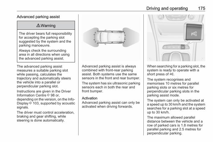
Driving and operating 175
Advanced parking assist
9 Warning
The driver bears full responsibilityfor accepting the parking slotsuggested by the system and theparking manoeuvre.Always check the surroundingarea in all directions when usingthe advanced parking assist.
The advanced parking assistmeasures a suitable parking slotwhile passing, calculates thetrajectory and automatically steersthe vehicle into a parallel orperpendicular parking slot.Instructions are given in the DriverInformation Centre 3 98 or,depending on the version, on the Info-Display 3 103, supported by acousticsignals.The driver must control acceleration,braking and gear shifting, whilesteering is done automatically.
Advanced parking assist is alwayscombined with front-rear parkingassist. Both systems use the samesensors in the front and rear bumper.The system has six ultrasonic parkingsensors each in both the rear andfront bumper.
ActivationAdvanced parking assist can only beactivated when driving forwards.
When searching for a parking slot, thesystem is ready to operate with ashort press of (.The system recognises andmemorises 10 metres for parallelparking slots or six metres forperpendicular parking slots in theparking assist mode.The system can only be activated ata speed up to 30 km/h and the systemsearches for a parking slot at a speedup to 30 km/h.The maximum allowed paralleldistance between the vehicle and arow of parked cars is 1.8 metres forparallel parking and 2.5 metres forperpendicular parking.

176 Driving and operating
FunctionalityParking slot searching mode,indication in the Driver InformationCentre
Select parallel or perpendicularparking slot in Driver InformationCentre by long press on (.The system is configured to detectparking slots by default on thepassenger side. To detect parkingslots on the driver side, switch on turnsignal indicator on the driver side.
When a slot is detected, a visualfeedback in the Driver InformationCentre and an acoustic signal isgiven.
Indication in the Colour-Info-Display
Select parallel or perpendicularparking slot by tapping the respectiveicon on the display.Select parking side by tapping therespective icon on the display.

Driving and operating 177
When a slot is detected, a visualfeedback on the Colour-Info-Displayand an acoustic signal is given.If the driver does not stop the vehicleafter a parking slot is proposed, thesystem starts to search for anothersuitable parking slot.Park guiding modeThe parking slot suggestion of thesystem is accepted when the vehicleis stopped by the driver within10 metres for parallel parking slots orsix metres for perpendicular parkingslots after the Stop message is given.The system calculates the optimalpath into the parking slot.
A brief vibration in the steering wheelafter engaging reverse gear indicatesthat the steering is controlled by thesystem. Then the vehicle is steeredinto the slot automatically by givingthe driver detailed instructions forbraking, accelerating and gearshifting. The driver must keep handsaway from the steering wheel.Always pay attention to the sound ofthe front-rear parking assist.Continuous sound indicates that thedistance to an obstacle is less thanapprox. 30 cm.If, for any reason, the driver must takeover control of the steering, hold thesteering wheel only at the outer edge.Automatic steering is cancelled in thisevent.Display indicationThe instructions on the display show:● General hints and warning
messages.● A hint when driving faster than
30 km/h during parking slotsearching mode.
● The demand to stop the vehicle,when a parking slot is detected.
● The direction of driving during theparking manoeuvre.
● The demand to shift into reverseor first gear.
● The demand to accelerate orbrake.
● For some of the instructions aprogress bar is shown in theDriver Information Centre.
● The successful completion of theparking manoeuvre indicated bya pop-up symbol and a chime.
● The cancelling of a parkingmanoeuvre.
Display prioritiesAdvanced parking assist indication inthe Driver Information Centre can beinhibited by vehicle messages with ahigher priority. After approving themessage by pressing SET/CLR onthe turn signal lever or 9 on thesteering wheel, advanced parkingassist instructions appear again andthe parking manoeuvre can becontinued.

178 Driving and operating
DeactivationThe system is deactivated by:● a short press of (● parking manoeuvre successfully
ended● driving faster than 30 km/h during
parking slot search● driving faster than 8 km/h during
parking guidance● driver interference on steering
wheel detected● exceeding number of maximum
gear changes: eight cycles whenparallel parking or five cycleswhen perpendicular parking
● switching off the ignitionDeactivation by the driver or by thesystem during manoeuvring will beindicated by Parking Deactivated onthe display. Additionally, an acousticsignal sounds.
FaultA message appears when:● There is a fault in the system.● The driver did not successfully
complete the parkingmanoeuvre.
● The system is not operational.● Any of the deactivation reasons
described above apply.If an object is detected during parkinginstructions, Stop is indicated on thedisplay. Removing the object willresume the parking manoeuvre. If theobject is not removed, the system willbe deactivated. A long press of ( willactivate the system and search for anew parking slot.
Basic notes on parking assistsystems
9 Warning
Under certain circumstances,various reflective surfaces onobjects or clothing as well as
external noise sources may causethe system to fail to detectobstacles.Special attention must be paid tolow obstacles which can damagethe lower part of the bumper.
Caution
Performance of the system can bereduced when sensors arecovered, e.g. by ice or snow.Performance of the parking assistsystem can be reduced due toheavy loading.Special conditions apply if thereare taller vehicles in the vicinity(e.g. off-road vehicles, mini vans,vans). Object identification andcorrect distance indication in theupper part of these vehiclescannot be guaranteed.Objects with a very small reflectioncross-section, e.g. objects ofnarrow size or soft materials, maynot be detected by the system.

Driving and operating 179
Parking assist systems do notdetect objects outside thedetection range.
NoteIt is possible that the sensor detectsa non-existing object caused byecho disturbance from externalacoustic noise or mechanicalmisalignments (sporadic falsewarnings may occur).Make sure that the front numberplate is properly mounted (not bentand no gaps to the bumper on the leftor right side) and the sensors arefirmly in place.Advanced parking assist systemmay not respond to changes in theavailable parking space afterinitiating a parking manoeuvre. Thesystem may recognize an entry, agateway, a courtyard or even acrossing as a parking slot. Afterselecting reverse gear the system
will start a parking manoeuvre. Takecare regarding the availability of thesuggested parking slot.Surface irregularities, e.g. onconstruction zones, are not detectedby the system. The driver acceptsresponsibility.NoteAfter production, the systemrequires a calibration. For optimalparking guidance, a driving distanceof at least 10 km, including a numberof bends, is required.
Side blind spot alertThe Side blind spot alert systemdetects and reports objects on eitherside of the vehicle, within a specified"blind spot" zone. The system alertsvisually in each exterior mirror, whendetecting objects that may not bevisible in the interior and exteriormirrors.Side blind spot alert uses some of theadvanced parking assist sensorswhich are located in the front and rearbumper on both sides of the vehicle.
9 Warning
Side blind spot alert does notreplace driver vision.The system does not detect:
● vehicles outside the side blindzones which may be rapidlyapproaching
● pedestrians, cyclists or animalsBefore changing a lane, alwayscheck all mirrors, look over theshoulder and use the turn signal.
When the system detects a vehicle inthe side blind zone while drivingforward, either while passing avehicle or being passed, an yellowwarning symbol B will illuminate inthe relevant exterior mirror. If thedriver then activates the turn signal,the warning symbol B starts flashingyellow as a warning not to changelanes.

180 Driving and operating
Side blind spot alert is active fromspeeds of 10 km/h up to 140 km/h.Driving faster than 140 km/hdeactivates the system, indicated bylow lighting warning symbols B inboth exterior mirrors and by amessage in the Driver InformationCentre. Reducing the speed againwill extinguish the warning symbols. Ifa vehicle is then detected in the blindzone, the warning symbols B willilluminate as normal on the relevantside.When the vehicle is started, bothexterior mirror displays will brieflycome on to indicate that the system isoperating.
The system can be activated ordeactivated in the Info-Display,vehicle personalisation 3 107.Deactivation is indicated by amessage in the Driver InformationCentre.
Detection zonesThe detection zones start at the rearbumper and extend approx.three metres rearwards and to thesides. The height of the zone isapprox. between half a metre andtwo metres off the ground.Side blind spot alert is designed toignore stationary objects, e.g.guardrails, posts, curbs, walls andbeams. Parked vehicles or oncomingvehicles are not detected.
FaultOccasional missed alerts can occurunder normal circumstances and willincrease in wet conditions.Side blind spot alert does not operatewhen the left or right corners of therear bumper are covered with mud,
dirt, snow, ice, slush, or in heavyrainstorms. Cleaning instructions3 237.In the event of a fault in the system orif the system does not work due totemporary conditions, the symbols inthe mirrors will be permanentlyilluminated and a message isdisplayed in the Driver InformationCentre. Seek the assistance of aworkshop.
Rear view cameraThe rear view camera assists thedriver when reversing by displaying aview of the area behind the vehicle.The view of the camera is displayedin the Colour-Info-Display.
9 Warning
The rear view camera does notreplace driver vision. Note thatobjects that are outside thecamera's field of view and theadvanced parking assist sensors,

Driving and operating 181
e.g. below the bumper orunderneath the vehicle, are notdisplayed.Do not reverse the vehicle by onlylooking at the Info-Display andcheck the surrounding areabehind and around the vehiclebefore reversing.
ActivationRear view camera is automaticallyactivated when reverse gear isengaged.
Functionality
The camera is mounted between thenumber plate lights and has a viewingangle of 130°.
The area displayed by the camera islimited. The distance of the image thatappears on the display differs fromthe actual distance.
Guiding linesDynamic guiding lines are horizontallines in one metre intervals projectedon the picture to define the distanceto shown objects.
Trajectory lane of the vehicle isshown in accordance with thesteering angle.
Warning symbolsWarning symbols are indicated astriangles 9 on the picture, which showobstacles detected by the rearsensors of the advanced parkingassist.Additionally 9 appears on the top lineof the Info-Display with the warning tocheck the vehicle surrounding.

182 Driving and operating
Display settingsBrightness and contrast can be set bytapping the touch screen displaywhen rear view camera is active.
DeactivationThe camera is switched off when acertain forward speed is exceeded orif reverse gear is not engaged forapprox. 15 seconds. Rear viewcamera can be manually deactivatedin the vehicle personalisation menu inthe Colour-Info-Display. Select therelevant setting in Settings, I Vehicle.
Deactivation of guiding lines andwarning symbols
7'' Colour-Info-Display: Activation ordeactivation of the visual guiding linesand the warning symbols can bechanged by touch buttons in the lowerzone of the display.8'' Colour-Info-Display: Activation ordeactivation of the visual guiding linesand the warning symbols can bechanged in the Settings menu in theInfo-Display. Select the relevantsetting in Settings, I Vehicle.Info-Display 3 103.Vehicle personalisation 3 107.
FaultFault messages are displayed with a9 on the top line of the Info-Display.The rear view camera may notoperate properly when:● The surrounding is dark.● The sun or the beam of
headlights is shining directly intothe camera lens.
● Ice, snow, mud, or anything elsecovers the camera lens. Cleanthe lens, rinse it with water, andwipe it with a soft cloth.
● The vehicle is towing a trailer.● The vehicle had a rear end
accident.● There are extreme temperature
changes.
Traffic sign assistantFunctionalityTraffic sign assistant detectsdesignated traffic signs via a frontcamera and displays them in theDriver Information Centre.If the vehicle is equipped with anembedded navigation system, trafficsigns fom data maps may be includedadditionally.

Driving and operating 183
Traffic signs, which will be detected,are:Limit and no passing signs● speed limit● no passing● end of speed limit● end of no passing
Road signsBeginning and end of:● city regions (country specific)● motorways● A-roads● play streets
Add on signs● additional hints to traffic signs● restriction of trailer towing● tractor constraints● wet warning● ice warning● time constraints● distance constraints● direction arrows
Speed limit signs and no passingsigns are displayed in the DriverInformation Centre until the nextspeed limit sign or end of speed limitis detected or up to a defined signtimeout.
Indication of multiple signs on thedisplay is possible.
An exclamation mark in a frameindicates that there is an additionalsign detected which cannot be clearlyidentified by the system.The system operates without loss ofperformance up to a speed of200 km/h depending on the lightingconditions. At night the system isactive up to a speed of 160 km/h.
Display indicationInformation about the currently validtraffic signs is available on thedesignated traffic sign assistant pagein the Driver Information Centre.Additionally, the currently valid speedlimit is displayed permanently in thelower line of the Driver InformationCentre. In case a speed limit withaddon is available, a + symbol isdisplayed in this area.
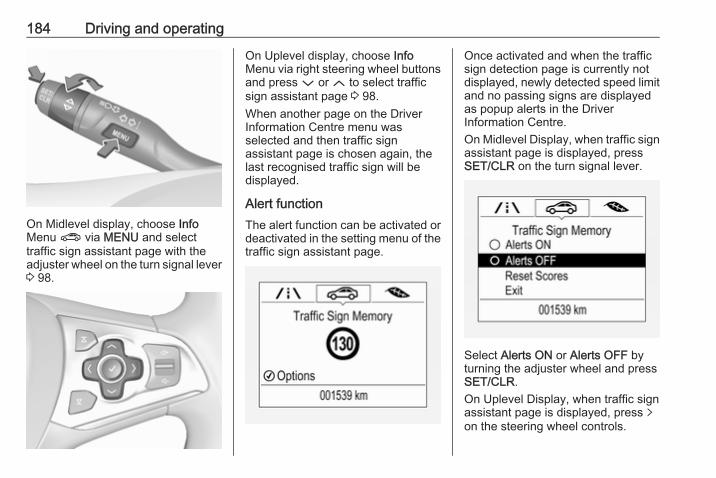
184 Driving and operating
On Midlevel display, choose InfoMenu ? via MENU and selecttraffic sign assistant page with theadjuster wheel on the turn signal lever3 98.
On Uplevel display, choose InfoMenu via right steering wheel buttonsand press P or Q to select trafficsign assistant page 3 98.When another page on the DriverInformation Centre menu wasselected and then traffic signassistant page is chosen again, thelast recognised traffic sign will bedisplayed.
Alert functionThe alert function can be activated ordeactivated in the setting menu of thetraffic sign assistant page.
Once activated and when the trafficsign detection page is currently notdisplayed, newly detected speed limitand no passing signs are displayedas popup alerts in the DriverInformation Centre.On Midlevel Display, when traffic signassistant page is displayed, pressSET/CLR on the turn signal lever.
Select Alerts ON or Alerts OFF byturning the adjuster wheel and pressSET/CLR.On Uplevel Display, when traffic signassistant page is displayed, press qon the steering wheel controls.

Driving and operating 185
Activate alerts by setting J,deactivate alerts by setting I viabutton 9.Pop-up alert is displayed for approx.eight seconds in the DriverInformation Centre.
System resetThe content of the traffic sign displaycan be cleared in the setting menu ofthe traffic sign assistant page byselecting Reset and confirm bypressing SET/CLR on the turn signallever or 9 on the steering wheelcontrols.
Alternatively, SET/CLR or 9 can bepressed for three seconds to clear thecontent of the page.Upon successful reset, a chime willsound and the following “DefaultSign” is indicated until the next trafficsign is detected or provided by mapdata of the navigation system.
In some cases, traffic sign assistant iscleared up automatically by thesystem.
Clearing of traffic signsThere are different scenarios thatlead to clearing the currentlydisplayed traffic signs. After clearing,the “Default Sign” or a sign fromnavigation map data is displayed inthe Driver Information Centre.
Reasons for signs being cleared:● A predefined distance was driven
or time has elapsed (differs foreach sign type)
● Vehicle drives through a turn● If no navigation map data is
available and speed becomesslower than 52 km/h (city entrydetection)
● If navigation map data isavailable and a city entry / exitwas detected due to map datachange
Traffic sign detection inconjunction with navigationsystemIf the vehicle is equipped with anavigation system, the currentlydisplayed sign can either originatefrom optical sign detection or from themap data.If the currently displayed signoriginates from map data and the mapinformation changes, a new sign willbe displayed. This might lead to

186 Driving and operating
detection of a new sign although nosign on the road might have beenpassed.
FaultTraffic sign assistant may not operatecorrectly if:● The area of the windscreen,
where the front camera islocated, is not clean or affectedby foreign items, e.g. stickers.
● Traffic signs are completely orpartially covered or difficult todiscern.
● There are adverse environmentalconditions, e.g. heavy rain, snow,direct sunlight or shadows.
● Traffic signs are incorrectlymounted or damaged.
● Traffic signs do not comply withthe Vienna Convention on trafficsigns (Wiener Übereinkommenüber Straßenverkehrszeichen).
Caution
The system is intended to help thedriver within a defined speedrange to discern certain trafficsigns. Do not ignore traffic signswhich are not displayed by thesystem.The system does not discern anyother than the conventional trafficsigns that might give or end aspeed limit.Do not let this special featuretempt you into taking risks whendriving.Always adapt speed to the roadconditions.The driver assistance systems donot relieve the driver from fullresponsibility for vehicleoperation.
Lane keep assistLane keep assist helps to avoidcrashes due to unintentional lanedepartures. The front cameraobserves the lane markings. If thevehicle approaches a lane marking,
the steering wheel is gently turned toposition the vehicle back into the lane.Override the system by turning thesteering wheel.Crossing a lane marking significantlywithout overriding lane keep assiststarts a visual and acoustic warning.Unintended lane departure isassumed● without using turn signal● using the turn signal in the
opposite direction of the lanedeparture
● without braking● without acceleration● without active steering.NoteThe system is switched off duringdetection of ambiguous lanemarkings, e.g. in construction areas.NoteThe system may be switched off, if itdetects lanes, which are too narrow,too wide or too much curved.

Driving and operating 187
Activation
The lane keep assist is activated bypressing a. The illuminated LED inthe button indicates that the system isswitched on.
When the control indicator a in theinstrument cluster illuminates green,the system is ready to assist.
The system is operable at vehiclespeeds between 60 km/h and180 km/h and if lane markings areavailable.The system gently turns the steeringwheel and the control indicator achanges to yellow, if the vehicleapproaches a detected lane markingwithout using the turn signal in thatdirection.The system alerts by flashing atogether with three chimes, from therespective direction, if the lane isdeparted significantly.The system can not operate when nolane marking is detected.If the system only detects lanemarkings on one side of the road, itwill only assist for this side.Lane keep assist detects hands-offdriving. In this case a message in theDriver Information Centre pops upand a chime sounds as long as lanekeep assist detects hands-off driving.
DeactivationThe system is deactivated bypressing a, the LED in the buttonextinguishes.
FaultThe system performance may beaffected by:● Windscreen not clean or affected
by foreign items, e.g. stickers● Close vehicles ahead● Banked roads● Winding or hilly roads● Road edges● Roads with poor lane markings● Sudden lighting changes● Adverse environmental
conditions like heavy rain orsnow
● Vehicle modifications, e.g. tyres.Switch off the system, if the system isfaulted by tar marks, shadows, roadcracks, temporary or constructionlane markings, or other roadimperfections.

188 Driving and operating
9 Warning
Always keep your attention on theroad and maintain proper vehicleposition within the lane, otherwisevehicle damage, injury or deathcould occur.Lane keep assist does notcontinuously steer the vehicle.The system may not keep thevehicle in the lane or give an alert,even if a lane marking is detected.Lane keep assist may not provideenough steering to avoid a lanedeparture.The system may not detect hands-off driving due to externalinfluences (road condition andsurface, weather etc). The driverhas full responsibility to control thevehicle and is always required tokeep the hands on the steeringwheel while driving.Using the system while towing atrailer or on slippery roads couldcause loss of control of the vehicleand a crash. Switch the system off.
FuelFuel for petrol enginesOnly use unleaded fuel that complieswith European standard EN 228 orE DIN 51626-1 or equivalent.The engine is capable of running withfuel that contains up to 10% ethanol(e.g. named E10).Use fuel with the recommendedoctane rating 3 248.
Caution
Do not use fuel or fuel additivesthat contain metallic compoundssuch as manganese-basedadditives. This may cause enginedamage.
Caution
Use of fuel that does not comply toEN 228 or E DIN 51626-1 orequivalent can lead to deposits orengine damage.
Caution
Use of fuel with too low an octanerating could lead to uncontrolledcombustion and engine damage.
Fuel for diesel enginesOnly use diesel fuel that complieswith EN 590.In countries outside the EuropeanUnion use Euro-Diesel fuel with asulphur concentration below 50 ppm.
Caution
Use of fuel that does not comply toEN 590 or similar can lead toengine powerloss, increased wearor engine damage.
Do not use marine diesel oils, heatingoils, Aquazole and similar diesel-water emulsions. Diesel fuels mustnot be diluted with fuels for petrolengines.

Driving and operating 189
Refuelling
9 Danger
Before refuelling, switch offignition and any external heaterswith combustion chambers.Follow the operating and safetyinstructions of the filling stationwhen refuelling.
9 Danger
Fuel is flammable and explosive.No smoking. No naked flames orsparks.If you can smell fuel in yourvehicle, have the cause of thisremedied immediately by aworkshop.
Caution
In case of misfuelling, do notswitch on ignition.
Fuel filler flap is located at right rearside of the vehicle.
The fuel filler flap can only be openedif the vehicle is unlocked. Release thefuel filler flap by pushing the flap.To open, turn the cap slowlyanticlockwise.

190 Driving and operating
The fuel filler cap can be retained inthe bracket on the fuel filler flap.To refuel, fully insert the pump nozzleand switch it on.After automatic cut-off, it can betopped up with max. two doses of fuel.
Caution
Wipe off any overflowing fuelimmediately.
To close, turn the fuel filler capclockwise until it clicks.Close the flap and engage.
Fuel filler capOnly use genuine fuel filler caps.Diesel-engined vehicles have specialfuel filler caps.
Fuel consumption - CO2-EmissionsThe fuel consumption (combined) ofthe model Opel Astra is within a rangeof 5.7 to 3.4 l/100 km.
The CO2 emission (combined) iswithin a range of 131 to 90 g/km.For the values specific for yourvehicle, refer to the EEC Certificate ofConformity provided with your vehicleor other national registrationdocuments.
General informationThe official fuel consumption andspecific CO2 emission figures quotedrelate to the EU base model withstandard equipment.Fuel consumption data and CO2emission data are determinedaccording to regulation R (EC)No. 715/2007 (in the latest applicableversion), taking into consideration thevehicle weight in running order, asspecified by the regulation.The figures are provided only for thepurpose of comparison betweendifferent vehicle variants and mustnot be taken as a guarantee for theactual fuel consumption of aparticular vehicle. Additionalequipment may result in slightlyhigher results than the stated
consumption and CO2 figures.Furthermore, fuel consumption isdependent on personal driving styleas well as road and traffic conditions.

Driving and operating 191
Trailer hitchGeneral informationOnly use towing equipment that hasbeen approved for your vehicle.Entrust retrofitting of towingequipment to a workshop. It may benecessary to make changes thataffect the cooling system, heatshields or other equipment.The bulb outage detection function fortrailer brake light cannot detect apartial bulb outage, e.g. in case of fourtimes five watt bulbs, the function onlydetects lamp outage when only asingle five Watt lamp remains or noneremain.Fitting of towing equipment couldcover the opening of the towing eye.If this is the case use the coupling ballbar for towing. Always keep thecoupling ball bar in the vehicle whennot in use.
Driving characteristics andtowing tipsBefore attaching a trailer, lubricatethe coupling ball. However, do not doso if a stabiliser, which acts on thecoupling ball, is being used to reducesnaking movements.For trailers with low driving stabilityand caravan trailers with a permittedgross vehicle weight of more than1300 kg the use of a stabiliser isstrongly recommended when drivingabove 80 km/h.If the trailer starts snaking, drive moreslowly, do not attempt to correct thesteering and brake sharply ifnecessary.When driving downhill, drive in thesame gear as if driving uphill anddrive at a similar speed.Adjust tyre pressure to the valuespecified for full load 3 254.
Trailer towingTrailer loadsThe permissible trailer loads arevehicle and engine-dependentmaximum values which must not beexceeded. The actual trailer load isthe difference between the actualgross weight of the trailer and theactual coupling socket load with thetrailer coupled.The permissible trailer loads arespecified in the vehicle documents. Ingeneral, they are valid for gradientsup to max. 12%.The permitted trailer load applies upto the specified incline and up to analtitude of 1000 metres above sealevel. Since engine power decreasesas altitude increases due to the airbecoming thinner, therefore reducingclimbing ability, the permissible grosstrain weight also decreases by 10%for every 1000 metres of additionalaltitude. The gross train weight doesnot have to be reduced when drivingon roads with slight inclines (less than8%, e.g. motorways).

192 Driving and operating
The permissible gross train weightmust not be exceeded. This weight isspecified on the identification plate3 243.
Vertical coupling loadThe vertical coupling load is the loadexerted by the trailer on the couplingball. It can be varied by changing theweight distribution when loading thetrailer.The maximum permissible verticalcoupling load (75 kg) is specified onthe towing equipment identificationplate and in the vehicle documents.Always aim for the maximum load,especially in the case of heavytrailers. The vertical coupling loadshould never fall below 25 kg.
Rear axle loadWhen the trailer is coupled and thetowing vehicle fully loaded, thepermissible rear axle load (seeidentification plate or vehicledocuments) may be exceeded by40 kg. If the permissible rear axle loadis exceeded, a maximum speed of100 km/h applies.
Towing equipment
Caution
When operating without a trailer,remove the coupling ball bar.
Stowage of coupling ball bar
The bag with the coupling ball bar isstowed in the rear stowagecompartment on the floor.Place the strap through the rearlashing eye, wrap around twice andtighten the strap to secure the bag.
Fitting the coupling ball bar
Disengage and fold down the socket.Remove the sealing plug from theopening for the coupling ball bar andstow it.

Driving and operating 193
Checking the tensioning of thecoupling ball bar
● Red marking on rotary knob mustpoint towards green marking oncoupling ball bar.
● The gap between the rotary knoband the coupling ball bar must beapprox. 6 mm.
● The key must be in position c.Otherwise, the coupling ball bar mustbe tensioned before being inserted:● Unlock coupling ball bar by
turning key to position c.
● Pull out rotary knob and turnclockwise as far as it will go.
Inserting the coupling ball bar
Insert the tensioned coupling ball barin the opening and push firmlyupwards until it audibly engages.The rotary handle snaps back into itsoriginal position resting against thecoupling ball bar without a gap.
9 Warning
Do not touch rotary handle duringinsertion.
Lock the coupling ball bar by turningthe key to position e. Remove the keyand close the protective flap.
Eye for break-away stopping cable

194 Driving and operating
Attach breakaway stopping cable toeye.
Check that the coupling ball bar iscorrectly installed● Green marking on rotary knob
must point towards greenmarking on coupling ball bar.
● There must be no gap betweenthe rotary handle and thecoupling ball bar.
● The coupling ball bar must befirmly engaged in the opening.
● The coupling ball bar must belocked and the key removed.
9 Warning
Towing a trailer is permitted onlywhen a coupling ball bar is fittedcorrectly. If the coupling ball bardoes not engage correctly, seekthe assistance of a workshop.
Dismounting the coupling ball bar
Open the protective flap and turn thekey to position c to unlock thecoupling ball bar.Pull out rotary handle and turnclockwise as far as it will go. Pull outcoupling ball bar downwards.Insert sealing plug in opening. Foldaway socket.
Trailer stability assistIf the system detects snakingmovements, engine power is reducedand the vehicle/trailer combination is
selectively braked until the snakingceases. While system is working keepsteering wheel as still as possible.Trailer stability assist is a function ofthe Electronic Stability Control 3 161.

Vehicle care 195
Vehicle care
General Information ................... 195Accessories and vehiclemodifications .......................... 195
Vehicle storage ........................ 196End-of-life vehicle recovery ..... 196
Vehicle checks ........................... 197Performing work ...................... 197Bonnet ..................................... 197Engine oil ................................. 198Engine coolant ......................... 199Washer fluid ............................ 200Brakes ..................................... 200Brake fluid ............................... 200Vehicle battery ......................... 201Diesel fuel system bleeding ..... 202Wiper blade replacement ........ 203
Bulb replacement ....................... 203Halogen headlights .................. 203Fog lights ................................. 205Tail lights ................................. 206Side turn signal lights .............. 209Number plate light ................... 210Interior lights ............................ 211Instrument panel illumination ... 211
Electrical system ........................ 211Fuses ....................................... 211Engine compartment fuse box . 212Instrument panel fuse box ....... 214Load compartment fuse box .... 216
Vehicle tools .............................. 218Tools ........................................ 218
Wheels and tyres ....................... 218Winter tyres ............................. 218Tyre designations .................... 219Tyre pressure .......................... 219Tyre pressure monitoringsystem .................................... 220
Tread depth ............................. 224Changing tyre and wheel size . 225Wheel covers ........................... 225Tyre chains .............................. 225Tyre repair kit .......................... 225Wheel changing ....................... 228Spare wheel ............................ 231
Jump starting ............................. 233Towing ....................................... 235
Towing the vehicle ................... 235Towing another vehicle ........... 236
Appearance care ....................... 237Exterior care ............................ 237Interior care ............................. 238
General InformationAccessories and vehiclemodificationsWe recommend the use of genuineparts and accessories and factoryapproved parts specific for yourvehicle type. We cannot assess orguarantee reliability of other products- even if they have a regulatory orotherwise granted approval.Do not make any modifications to theelectrical system, e.g. changes ofelectronic control units (chip tuning).
Caution
When transporting the vehicle ona train or on a recovery vehicle, themud flaps might be damaged.

196 Vehicle care
Vehicle storageStorage for a long period of timeIf the vehicle is to be stored for severalmonths:● Wash and wax the vehicle.● Have the wax in the engine
compartment and underbodychecked.
● Clean and preserve the rubberseals.
● Fill up fuel tank completely.● Change the engine oil.● Drain the washer fluid reservoir.● Check the coolant antifreeze and
corrosion protection.● Adjust tyre pressure to the value
specified for full load.● Park the vehicle in a dry, well
ventilated place. Engage first orreverse gear or set selector leverto P. Prevent the vehicle fromrolling.
● Do not apply the parking brake.
● Open the bonnet, close all doorsand lock the vehicle.
● Disconnect the clamp from thenegative terminal of the vehiclebattery. Beware that all systemsare not functional, e.g. anti-theftalarm system.
Putting back into operationWhen the vehicle is to be put back intooperation:● Connect the clamp to the
negative terminal of the vehiclebattery. Activate the electronicsof the power windows.
● Check tyre pressure.● Fill up the washer fluid reservoir.● Check the engine oil level.● Check the coolant level.● Fit the number plate if necessary.
End-of-life vehicle recoveryInformation on end-of-life vehiclerecovery centres and the recycling ofend-of-life vehicles is available on ourwebsite, where legally required. Onlyentrust this work to an authorisedrecycling centre.

Vehicle care 197
Vehicle checksPerforming work
9 Warning
Only perform engine compartmentchecks when the ignition is off.The cooling fan may startoperating even if the ignition is off.
9 Danger
The ignition system usesextremely high voltage. Do nottouch.
BonnetOpening
Pull the release lever and return it toits original position.
Move the safety catch sideways to theleft vehicle side and open the bonnet.
Secure the bonnet support.

198 Vehicle care
If the bonnet is opened during anAutostop, the engine will be restartedautomatically for safety reasons.
ClosingBefore closing the bonnet, press thesupport into the holder.Lower the bonnet and let it fall into thelatch from a low height (20-25 cm).Check that the bonnet is engaged.
Caution
Do not press the bonnet into thelatch to avoid dents.
Engine oilCheck the engine oil level manuallyon a regular basis to prevent damageto the engine. Ensure that the correctspecification of oil is used.Recommended fluids and lubricants3 241.Check with the vehicle on a levelsurface. The engine must be atoperating temperature and switchedoff for at least five minutes.
Pull out the dipstick, wipe it clean,insert it to the stop on the handle, pullout and read the engine oil level.Insert dipstick to the stop on thehandle and make half a turn.Different dipsticks are useddepending on engine variant.
When the engine oil level hasdropped to the MIN mark, top upengine oil.
We recommend the use of the samegrade of engine oil that was used atlast change.

Vehicle care 199
The engine oil level must not exceedthe MAX mark on the dipstick.
Caution
Overfilled engine oil must bedrained or suctioned out.
Capacities 3 253.Fit the cap on straight and tighten it.
Engine coolantThe coolant provides freezeprotection down to approx. -28 °C. Incold regions with very lowtemperatures, the factory filledcoolant provides frost protectiondown to approx. -37 °C.
Caution
Only use approved antifreeze.
Coolant level
Caution
Too low a coolant level can causeengine damage.
If the cooling system is cold, thecoolant level should be above thefilling line mark. Top up if the level islow.
9 Warning
Allow the engine to cool beforeopening the cap. Carefully openthe cap, relieving the pressureslowly.
To top up, use a 1:1 mixture ofreleased coolant concentrate mixedwith clean tap water. If no coolantconcentrate is available, use cleantap water. Install the cap tightly. Havethe coolant concentration checkedand have the cause of the coolantloss remedied by a workshop.

200 Vehicle care
Washer fluid
Fill with clean water mixed with asuitable quantity of approvedwindscreen washer fluid whichcontains antifreeze.
Caution
Only washer fluid with a sufficientantifreeze concentration providesprotection at low temperatures ora sudden drop in temperature.
BrakesIn the event of minimum thickness ofthe brake lining, a squealing noisesounds during braking.Continued driving is possible buthave the brake lining replaced assoon as possible.Once new brake linings are installed,do not brake unnecessarily hard forthe first few journeys.
Brake fluid
9 Warning
Brake fluid is poisonous andcorrosive. Avoid contact with eyes,skin, fabrics and painted surfaces.
The brake fluid level must be betweenthe MIN and MAX marks.If fluid level is below MIN seek theassistance of a workshop.Brake and clutch fluid 3 241.

Vehicle care 201
Vehicle battery
The vehicle battery is located in theload compartment under a coverbehind the rear seats. There areconnecting points for jump starting inthe engine compartment.Jump starting 3 233.The vehicle battery is maintenance-free provided that the driving profileallows sufficient charging of thebattery. Short-distance-driving andfrequent engine starts can dischargethe battery. Avoid the use ofunnecessary electrical consumers.
Batteries do not belong in householdwaste. They must be disposed of atan appropriate recycling collectionpoint.Laying up the vehicle for more thanfour weeks can lead to batterydischarge. Disconnect the clamp fromthe negative terminal of the vehiclebattery.Ensure the ignition is switched offbefore connecting or disconnectingthe vehicle battery.Vehicle battery discharge protection3 128.
Replacing the vehicle batteryNoteAny deviation from the instructionsgiven in this section may lead totemporary deactivation of the stop-start system.
When the vehicle battery is beingreplaced, please ensure that thereare no open ventilation holes in thevicinity of the positive terminal. If aventilation hole is open in this area, itmust be closed off with a dummy cap,and the ventilation in the vicinity of thenegative terminal must be opened.In vehicles with an AGM (AbsorptiveGlass Mat) battery, make sure tohave the battery replaced withanother AGM battery.
An AGM battery can be identified bythe label on the battery. Werecommend the use of an originalOpel vehicle battery.

202 Vehicle care
NoteUsing an AGM vehicle batterydifferent from the original Opelvehicle battery may result in a lowerperformance.
We recommend that you have thevehicle battery replaced by aworkshop.Stop-start system 3 145.
Charging the vehicle battery
9 Warning
On vehicles with stop-startsystem, ensure that the chargingpotential does not exceed14.6 volts when using a batterycharger. Otherwise the vehiclebattery might be damaged.
Jump starting 3 233.
Warning label
Meaning of symbols:● No sparks, naked flames or
smoking.● Always shield eyes. Explosive
gases can cause blindness orinjury.
● Keep the vehicle battery out ofreach of children.
● The vehicle battery containssulphuric acid which could causeblindness or serious burninjuries.
● See the Owner's Manual forfurther information.
● Explosive gas may be present inthe vicinity of the vehicle battery.
Diesel fuel system bleedingIf the tank has been run dry, the dieselfuel system must be bled. Switch onthe ignition three times for15 seconds at a time. Then crank theengine for a maximum of40 seconds. Repeat this process afterno less than five seconds. If theengine fails to start, seek theassistance of a workshop.

Vehicle care 203
Wiper blade replacement
Lift the wiper arm until it stays in theraised position, press button todisengage the wiper blade andremove.Attach the wiper blade slightly angledto the wiper arm and push until itengages.Lower wiper arm carefully.
Wiper blade on the rear window
Lift wiper arm. Disengage wiper bladeas shown in illustration and remove.Attach the wiper blade slightly angledto the wiper arm and push until itengages.Lower wiper arm carefully.
Bulb replacementSwitch off the ignition and switch offthe relevant switch or close the doors.Only hold a new bulb at the base. Donot touch the bulb glass with barehands.Use only the same bulb type forreplacement.Replace headlight bulbs from withinthe engine compartment.
Bulb checkAfter a bulb replacement switch onthe ignition, operate and check thelights.
Halogen headlightsHalogen headlights with separatebulbs for low beam and high beam.
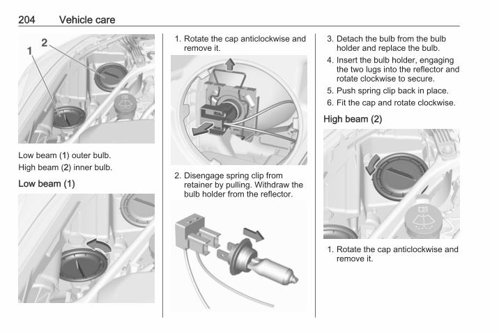
204 Vehicle care
Low beam (1) outer bulb.High beam (2) inner bulb.
Low beam (1)
1. Rotate the cap anticlockwise andremove it.
2. Disengage spring clip fromretainer by pulling. Withdraw thebulb holder from the reflector.
3. Detach the bulb from the bulbholder and replace the bulb.
4. Insert the bulb holder, engagingthe two lugs into the reflector androtate clockwise to secure.
5. Push spring clip back in place.6. Fit the cap and rotate clockwise.
High beam (2)
1. Rotate the cap anticlockwise andremove it.

Vehicle care 205
2. Disengage spring clip fromretainer by moving it forward andto the side. Swivel spring clipdownwards.
3. Withdraw the bulb holder from thereflector.
4. Detach the bulb from the bulbholder and replace the bulb.
5. Insert the bulb holder and installspring clip.Fit the cap and rotate clockwise.
Front turn signal lightIn case of defective LEDs, have themreplaced by a workshop.
Side lightIn case of defective LEDs, have themreplaced by a workshop.
Daytime running lightIn case of defective LEDs, have themreplaced by a workshop.
Fog lightsThe bulbs are accessible from theunderside of the vehicle.
1. Turn the bulb holder anti-clockwise and remove it from thereflector.

206 Vehicle care
2. Disengage the bulb socket fromthe plug connector by pressingthe retaining lug.
3. Remove and replace the bulbsocket with bulb and attach theplug connector.
4. Insert the bulb socket into thereflector by turning clockwise andengage.
Tail lights
1. Release the cover on therespective side and remove it.
2. Vehicles with tyre repair kit: Toreplace bulbs on the right side,first unscrew the plastic nut andtake out the insert with the sealantbottle.
3. Unscrew the plastic securing nutfrom the inside by hand.

Vehicle care 207
4. Carefully withdraw tail lightassembly from recess andremove.
5. Detach the cable from theretainer.
6. Press the three retaining lugs andremove the bulb carrier from thelight assembly.
7. Remove and replace the bulbs:Turn signal light (1)Tail light/brake light (2)
On version with LED tail lights andLED brake lights, only turn signallight bulb (1) can be removed andreplaced.
8. Attach the bulb carrier to the lightassembly.
9. Attach the cable to the retainer.10. Attach the light assembly to the
vehicle body and tighten thesecuring nut from the inside of theload compartment. Attach cover.
Depending on the version, tail lightsand brake lights are designed asLEDs. In case of failure, have LEDsreplaced by a workshop.

208 Vehicle care
Light assembly in the tailgate
1. Release the cover in the tailgateand remove it.
2. Unscrew the plastic securing nutby hand.
3. Carefully withdraw the lightassembly from the recesses andremove.
4. Detach the plug from the lightassembly.
5. Press the three retaining lugs andremove the bulb carrier from thelight assembly.

Vehicle care 209
On version with LED tail lights, theposition of the retaining lugs isslightly different.
6. Remove and replace the bulb:Tail light (1)Rear fog light (2) (left side)Reverse light (2) (right side)
On version with LED tail lightsonly reverse light bulb (1) (rightside) or rear fog light bulb (1) (leftside) can be removed andreplaced.
7. Insert the bulb carrier into the taillight assembly. Attach plug to thelight assembly. Fit light assemblyon the tailgate and tighten thescrew from the inside. Attachcover.
Depending on the version, tail lightsare designed as LEDs. In case offailure, have LEDs replaced by aworkshop.
Side turn signal lightsTo replace bulb, remove lamphousing:
1. Slide lamp to its left side andremove with its right end.

210 Vehicle care
2. Turn bulb holder anticlockwiseand remove from housing.
3. Pull bulb from bulb holder andreplace it.
4. Insert bulb holder and turnclockwise.
5. Insert left end of the lamp, slide tothe left and insert right end.
Number plate light
1. Insert screwdriver in recess of thecover, press to the side andrelease spring.
2. Remove lamp downwards, takingcare not to pull on the cable.
3. Remove bulb holder from lamphousing by turning anticlockwise.

Vehicle care 211
4. Pull bulb from bulb holder andreplace it.
5. Insert bulb holder into lamphousing and turn clockwise.
6. Insert lamp into bumper and letengage.
Interior lightsCourtesy light, reading lightsHave bulbs replaced by a workshop.
Load compartment lightHave bulbs replaced by a workshop.
Instrument panelilluminationHave bulbs replaced by a workshop.
Electrical systemFusesData on the replacement fuse mustmatch the data on the defective fuse.There are three fuse boxes in thevehicle:● engine compartment● instrument panel● load compartment
Before replacing a fuse, turn off therespective switch and the ignition.A blown fuse can be recognized by itsmelted wire. Do not replace the fuseuntil the cause of the fault has beenremedied.Some functions are protected byseveral fuses.Fuses may also be inserted withoutexistence of a function.
Fuse extractorA fuse extractor may be located in thefuse box in the engine compartment.

212 Vehicle care
Place the fuse extractor on thevarious types of fuse from the top orside, and withdraw fuse.
Engine compartment fusebox
The fuse box is in the front left of theengine compartment.Disengage the cover and remove it.

Vehicle care 213
No. Circuit
1 Starter
2 Starter
3 Exhaust sensor
4 Engine control module
5 Engine functions
6 Transmission control module
7 –
8 Engine control module
9 Climate control system
10 –
11 Tailgate locking system
12 Seat lumbar massage
13 After boil pump
14 –
15 Exhaust sensor
16 Fuel injection
17 Fuel injection
No. Circuit
18 –
19 –
20 –
21 –
22 ABS
23 Washer system for windscreenand rear window
24 –
25 Diesel fuel heating
26 Transmission control module
27 Power tailgate module
28 –
29 Heated rear window
30 –
31 –
32 DC transformer/LED display/Electrical heater/Climatecontrol/Glow plug controller/Fuel pump
No. Circuit
33 –
34 Horn
35 Power outlet load compartment
36 Right high beam (Halogen)/Right low beam (LED)
37 Left high beam (Halogen)
38 LED headlight/Automatic head‐light range adjustment
39 Front fog light
40 OnStar
41 Water in fuel sensor/Waterpump
42 Manual headlight range adjust‐ment
43 Fuel pump
44 Rear view camera/Inside rearview mirror/Trailer module/Power connector
45 LED headlight left/Automaticheadlight range adjustment left

214 Vehicle care
No. Circuit
46 Instrument cluster
47 Steering column lock
48 Rear wiper
49 Heated mirror
50 LED headlight right/Automaticheadlight range adjustmentright
51 Left low beam (LED)
52 Engine control module/Trans‐mission control module
53 –
54 Windscreen wiper
55 –
56 –
57 –
After having changed defective fuses,close the fuse box cover and pressuntil it engages.If the fuse box cover is not closedcorrectly, malfunction may occur.
Instrument panel fuse boxThe fuse box is located behind acover.
Pull the cover and remove.Vehicles with power connector:If the fuse cover has a powerconnector, it must be removed byusing an adapter and a screwdriver.The adapter is stowed in the glovebox3 66. The screwdriver is stowed in theload compartment 3 218.
Attach the adapter to the powerconnector.
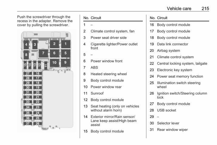
Vehicle care 215
Push the screwdriver through therecess in the adapter. Remove thecover by pulling the screwdriver.
No. Circuit
1 –
2 Climate control system, fan
3 Power seat driver side
4 Cigarette lighter/Power outletfront
5 –
6 Power window front
7 ABS
8 Heated steering wheel
9 Body control module
10 Power window rear
11 Sunroof
12 Body control module
13 Seat heating (only on vehicleswithout alarm horn)
14 Exterior mirror/Rain sensor/Lane keep assist/High beamassist
15 Body control module
No. Circuit
16 Body control module
17 Body control module
18 Body control module
19 Data link connector
20 Airbag system
21 Climate control system
22 Central locking system, tailgate
23 Electronic key system
24 Power seat memory function
25 Illumination switch steeringwheel
26 Ignition switch/Steering columnlock
27 Body control module
28 USB socket
29 –
30 Selector lever
31 Rear window wiper

216 Vehicle care
No. Circuit
32 Transmission control module(only on vehicles with stop-startsystem)
33 Anti-theft alarm system/Alarmhorn
34 Parking assist/Side blind spotalert/Infotainment system/USBsocket
35 OnStar
36 Info display/Instrument cluster/CD player
37 Infotainment system, radio
After having changed defective fuses,close the fuse box cover and pressuntil it engages.Vehicles with power connector:1. Apply the cover on the right side.
2. Fold the left side of the coverforwards. Take care that thesecuring clamp is guided asshown in the illustration.
Load compartment fuse boxThe fuse box is located on the left sideof the load compartment behind acover.
Remove the cover.
Disengage the fuse box cover andremove it.

Vehicle care 217
No. Circuit
1 –
2 –
3 Trailer
4 Power seat passenger side
5 –
6 Distance warning module
7 –
8 –
9 Rear seat heating (on vehicleswithout alarm horn)
10 –
11 –
12 Front seat heating (on vehicleswith alarm horn)
13 Rear seat heating (on vehicleswith alarm horn)
14 Heated steering wheel (on vehi‐cles with seat heating and alarmhorn)
No. Circuit
15 Seat ventilation
16 Trailer outlet
17 Trailer outlet
18 –
19 –
20 –
21 Electrical seat folding
22 –
After having changed defective fuses,close the fuse box cover and pressuntil it engages.

218 Vehicle care
Vehicle toolsToolsVehicle with spare wheel
The jack, the towing eye, a strap forsecuring a damaged wheel and thetools are located in the tool box belowthe spare wheel in the loadcompartment. Spare wheel 3 231.
Vehicles with tyre repair kit
Some tools and the towing eye arelocated together with the tyre repairkit in a tool box in the right wall of theload compartment.Open the cover of the storagecompartment.
Wheels and tyres
Tyre condition, wheel conditionDrive over edges slowly and at rightangles if possible. Driving over sharpedges can cause tyre and wheeldamage. Do not trap tyres on the kerbwhen parking.Regularly check the wheels fordamage. Seek the assistance of aworkshop in the event of damage orunusual wear.
Winter tyresWinter tyres improve driving safety attemperatures below 7 °C and shouldtherefore be fitted on all wheels.All tyre sizes are permitted as wintertyres 3 254.In accordance with country-specificregulations, affix the speed sticker inthe driver's field of view.

Vehicle care 219
Tyre designationsE.g. 215/60 R 16 95 H215 : Tyre width, mm60 : Cross-section ratio (tyre height
to tyre width), %R : Belt type: RadialRF : Type: RunFlat16 : Wheel diameter, inches95 : Load index e.g. 95 is
equivalent to 690 kgH : Speed code letter
Speed code letter:Q : up to 160 km/hS : up to 180 km/hT : up to 190 km/hH : up to 210 km/hV : up to 240 km/hW : up to 270 km/h
Choose a tyre appropiate for themaximum speed of your verhicle.The maximum speed is achievable atkerb weight with driver (75 kg) plus125 kg payload. Optional equipmentcould reduce the maximum speed ofthe vehicle.Performance 3 250.
Tyre pressureCheck the pressure of cold tyres atleast every 14 days and before anylong journey. Do not forget the sparewheel.This also applies to vehicles with tyrepressure monitoring system.Unscrew the valve cap.
Tyre pressure 3 254.The tyre pressure information labelon the left door frame indicates theoriginal equipment tyres and thecorrespondent tyre pressures.
The tyre pressure data refers to coldtyres. It applies to summer and wintertyres.Always inflate the spare tyre to thepressure specified for full load.The ECO tyre pressure serves toachieve the smallest amount of fuelconsumption possible.Incorrect tyre pressures will impairsafety, vehicle handling, comfort andfuel economy and will increase tyrewear.Tyre pressures differ depending onvarious options. For the correct tyrepressure value, follow the procedurebelow:1. Identify the engine identifier code.
Engine data 3 248.2. Identify the respective tyre.
The tyre pressure tables show allpossible tyre combinations 3 254.For the tyres approved for yourvehicle, refer to the EEC Certificate ofConformity provided with your vehicleor other national registrationdocuments.

220 Vehicle care
The driver is responsible for correctadjustment of tyre pressure.
9 Warning
If the pressure is too low, this canresult in considerable tyre warm-up and internal damage, leading totread separation and even to tyreblow-out at high speeds.
If the tyre pressure must be reducedor increased on a vehicle with tyrepressure monitoring system, switchoff ignition.
Temperature dependencyThe tyre pressure depends on thetemperature of the tyre. Duringdriving, tyre temperature andpressure increase. Tyre pressurevalues provided on the tyreinformation label and tyre pressurechart are valid for cold tyres, whichmeans at 20 °C.The pressure increases by nearly10 kPa for a 10 °C temperatureincrease. This must be consideredwhen warm tyres are checked.
The tyre pressure value displayed inthe Driver Information Centre showsthe real tyre pressure. A cooled downtyre will show a decreased value,which does not indicate an air leak.
Tyre pressure monitoringsystemThe tyre pressure monitoring systemchecks the pressure of all four tyresonce a minute when vehicle speedexceeds a certain limit.
Caution
Tyre pressure monitoring systemwarns only about low tyre pressurecondition and does not replaceregular tyre maintenance by thedriver.
All wheels must be equipped withpressure sensors and the tyres musthave the prescribed pressure.
NoteIn countries where the tyre pressuremonitoring system is legallyrequired, the use of wheels withoutpressure sensors will invalidate thevehicle type approval.
The current tyre pressures can beshown in the Driver InformationCentre.Midlevel display:
Select the Tyre pressure page underthe Vehicle Information Menu ? inthe Driver Information Centre 3 98.Uplevel display:

Vehicle care 221
Select the Tyre pressure page underthe Info Menu in the DriverInformation Centre 3 98.System status and pressure warningsare displayed by a messageindicating the corresponding tyre inthe Driver Information Centre.The system considers the tyretemperature for the warnings.Temperature dependency 3 219.
A detected low tyre pressurecondition is indicated by the controlindicator w 3 96.If w illuminates, stop as soon aspossible and inflate the tyres asrecommended 3 254.If w flashes for 60-90 seconds thenilluminates continuously, there is afault in the system. Consult aworkshop.After inflating, some driving may berequired to update the tyre pressurevalues in the Driver InformationCentre. During this time w mayilluminate.If w illuminates at lower temperaturesand extinguishes after driving, thiscould be an indicator for approachinga low tyre pressure condition. Checktyre pressure.Vehicle messages 3 105.If the tyre pressure must be reducedor increased, switch off ignition.Only mount wheels with pressuresensors, otherwise the tyre pressurewill not be displayed and willuminates continuously.
A spare wheel or temporary sparewheel is not equipped with pressuresensors. The tyre pressuremonitoring system is not operationalfor these tyres. Control indicator willuminates. For the further threetyres, the system remainsoperational.The use of commercially-availableliquid tyre repair kits can impair thefunction of the system. Factory-approved repair kits can be used.Operating electronic devices or beingclose to facilities using similar wavefrequencies could disrupt the tyrepressure monitoring system.Each time the tyres are replaced, tyrepressure monitoring system sensorsmust be dismounted and serviced.For the screwed sensor, replacevalve core and sealing ring. For theclipped sensor, replace completevalve stem.
Vehicle loading statusAdjust tyre pressure to load conditionaccording to the tyre information labelor tyre pressure chart 3 254, andselect the appropriate setting in the

222 Vehicle care
Tyre load menu in the DriverInformation Centre 3 98. This settingis the reference for the tyre pressurewarnings.The Tyre load menu only appears ifthe vehicle is in a standstill and theparking brake is applied. On vehicleswith automatic transmission theselector lever has to be in P.Midlevel display:
Select the Tyre load page under theVehicle Information Menu ? in theDriver Information Centre 3 98.
Select● Light for comfort pressure up to
three people.● Eco for Eco pressure up to three
people.● Max for full loading.
Uplevel display:
Select the Tyre load page under theOptions Menu in the DriverInformation Centre 3 98.
Select● Light for comfort pressure up to
three people.● Eco for Eco pressure up to
three people.● Max for full loading.
Tyre pressure sensor matchingprocessEach tyre pressure sensor has aunique identification code. Theidentification code must be matchedto a new wheel position after rotatingthe wheels or exchanging thecomplete wheel set and if one or moretyre pressure sensors were replaced.The tyre pressure sensor matchingprocess should also be performedafter replacing a spare wheel with aroad wheel containing the tyrepressure sensor.The malfunction light w and thewarning message or code should gooff at the next ignition cycle. Thesensors are matched to the wheelpositions, using a relearn tool, in thefollowing order: left side front wheel,right side front wheel, right side rear

Vehicle care 223
wheel and left side rear wheel. Theturn signal light at the current activeposition is illuminated until sensor ismatched.Consult a workshop for service orpurchase a relearn tool. There aretwo minutes to match the first wheelposition, and five minutes overall tomatch all four wheel positions. If ittakes longer, the matching processstops and must be restarted.The tyre pressure sensor matchingprocess is:1. Apply the parking brake.2. Turn the ignition on.3. On vehicles with automatic
transmission: set the selectorlever to P.On vehicles with manualtransmission: select neutral.
4. Midlevel display:Use MENU on the turn signallever to select the VehicleInformation Menu ? in theDriver Information Centre.Uplevel display:
Press p on the steering wheel toopen main menu page.Select the Info page with Q or P.Confirm with 9.
5. Select the tyre pressure menu.Midlevel display:
Uplevel display:
6. Midlevel display:Press SET/CLR to begin thesensor matching process. Amessage requesting acceptanceof the process should bedisplayed.Press SET/CLR again to confirmthe selection. The horn soundstwice to indicate that the receiveris in relearn mode.Uplevel display:Press 9 to begin the sensormatching process. The hornsounds twice to indicate that thereceiver is in relearn mode.
7. Start with the left side front wheel.

224 Vehicle care
8. Place the relearn tool against thetyre sidewall, near the valve stem.Then press the button to activatethe tyre pressure sensor. A hornchirp confirms that the sensoridentification code has beenmatched to this wheel position.
9. Proceed to the right side frontwheel, and repeat the procedurein Step 8.
10. Proceed to the right side rearwheel, and repeat the procedurein Step 8.
11. Proceed to the left side rearwheel, and repeat the procedurein Step 8. The horn sounds twiceto indicate that the sensoridentification code has beenmatched to the left side rearwheel, and the tyre pressuresensor matching process is nolonger active.
12. Turn off the ignition.
13. Set all four tyres to therecommended air pressure levelas indicated on the tyre pressureinformation label.
14. Ensure the tyre loading status isset according to the selectedpressure 3 98.
Tread depthCheck tread depth at regularintervals.Tyres should be replaced for safetyreasons at a tread depth of 2-3 mm(4 mm for winter tyres).For safety reasons it is recommendedthat the tread depth of the tyres onone axle should not vary by more than2 mm.
The legally permissible minimumtread depth (1.6 mm) has beenreached when the tread has worndown as far as one of the tread wearindicators (TWI). Their position isindicated by markings on thesidewall.If there is more wear at the front thanthe rear, swap round front wheels andrear wheels periodically. Ensure thatthe direction of rotation of the wheelsremains the same.Tyres age, even if they are not used.We recommend tyre replacementevery six years.

Vehicle care 225
Changing tyre and wheelsizeIf tyres of a different size than thosefitted at the factory are used, it may benecessary to reprogramme thespeedometer as well as the nominaltyre pressure and make other vehiclemodifications.After converting to a different tyresize, have the label with tyrepressures replaced.Furthermore, the advanced parkingassist must be calibrated 3 171.
9 Warning
Use of unsuitable tyres or wheelsmay lead to accidents and willinvalidate the vehicle typeapproval.
Wheel coversWheel covers and tyres that arefactory approved for the respectivevehicle and comply with all of therelevant wheel and tyre combinationrequirements must be used.
If the wheel covers and tyres used arenot factory approved, the tyres mustnot have a rim protection ridge.Wheel covers must not impair brakecooling.
9 Warning
Use of unsuitable tyres or wheelcovers could lead to suddenpressure loss and therebyaccidents.
Tyre chains
Tyre chains are only permitted on thefront wheels.
Always use fine mesh chains that addno more than 10 mm to the tyre treadand the inboard sides (including chainlock).
9 Warning
Damage may lead to tyre blowout.
Tyre chains are permitted on tyres ofsize 195/65 R15, 205/55 R16 and215/55 R16.
Temporary spare wheelThe use of tyre chains is not permittedon the temporary spare wheel.
Tyre repair kitMinor damage to the tyre tread can berepaired with the tyre repair kit.Do not remove foreign bodies fromthe tyres.Tyre damage exceeding 4 mm or thatis at tyre's sidewall cannot be repairedwith the tyre repair kit.

226 Vehicle care
9 Warning
Do not drive faster than 80 km/h.Do not use for a lengthy period.Steering and handling may beaffected.
If you have a flat tyre:Apply the parking brake and engagefirst gear, reverse gear or P.
The tyre repair kit is on the right sidein the load compartment behind acover.1. Remove the sealant bottle.
2. Insert the thumb into the openingand pull out the compressor.
3. Remove the electrical connectioncable and air hose from thestowage compartments on theunderside of the compressor.
4. Screw the compressor air hose tothe connection on the sealantbottle.
5. Fit the sealant bottle into theretainer on the compressor.Set the compressor near the tyrein such a way that the sealantbottle is upright.

Vehicle care 227
6. Unscrew valve cap from defectivetyre.
7. Screw the filler hose to the tyrevalve.
8. The switch on the compressormust be set to J.
9. Connect the compressor plug tothe power outlet or cigarettelighter socket.To avoid discharging the battery,we recommend running theengine.
10. Set the rocker switch on thecompressor to I. The tyre is filledwith sealant.
11. The compressor pressure gaugebriefly indicates up to 6 bar whilstthe sealant bottle is emptying(approx. 30 seconds). Then thepressure starts to drop.
12. All of the sealant is pumped intothe tyre. Then the tyre is inflated.
13. The prescribed tyre pressureshould be obtained within tenminutes. Tyre pressure 3 254.When the correct pressure isobtained, switch off thecompressor.
If the prescribed tyre pressure isnot obtained within ten minutes,remove the tyre repair kit. Movethe vehicle one tyre rotation.Reattach the tyre repair kit andcontinue the filling procedure forten minutes . If the prescribed tyrepressure is still not obtained, thetyre is too badly damaged. Seekthe assistance of a workshop.Drain excess tyre pressure withthe button over the pressureindicator.Do not run the compressor longerthan ten minutes.

228 Vehicle care
14. Detach the tyre repair kit. Pushcatch on bracket to removesealant bottle from bracket. Screwthe tyre inflation hose to the freeconnection of the sealant bottle.This prevents sealant fromescaping. Stow tyre repair kit inload compartment.
15. Remove any excess sealantusing a cloth.
16. Take the label indicatingmaximum permitted speed fromthe sealant bottle and affix in thedriver's field of view.
17. Continue driving immediately sothat sealant is evenly distributedin the tyre. After driving approx.10 km (but no more than tenminutes), stop and check tyrepressure. Screw compressor airhose directly onto tyre valve andcompressor when doing this.
If tyre pressure is more than1.3 bar, set it to the correct value.Repeat the procedure until thereis no more loss of pressure.If the tyre pressure has fallenbelow 1.3 bar, the vehicle mustnot be used. Seek the assistanceof a workshop.
18. Stow away tyre repair kit in loadcompartment.
NoteThe driving characteristics of therepaired tyre are severely affected,therefore have this tyre replaced.
If unusual noise is heard or thecompressor becomes hot, turncompressor off for at least30 minutes.The built-in safety valve opens at apressure of 7 bar.Note the expiry date of the kit. Afterthis date its sealing capability is nolonger guaranteed. Pay attention tostorage information on sealantbottle.Replace the used sealant bottle.Dispose of the bottle as prescribedby applicable laws.The compressor and sealant can beused from approx. -30 °C.The adapters supplied can be usedto pump up other items e.g.footballs, air mattresses, inflatabledinghies etc. They are located on theunderside of the compressor. Toremove, screw on compressor airhose and withdraw adapter.
Wheel changingSome vehicles are equipped with atyre repair kit instead of a spare wheel3 225.

Vehicle care 229
Make the following preparations andobserve the following information:● Park the vehicle on a level, firm
and non-skid surface. The frontwheels must be in the straight-ahead position.
● Apply the parking brake andengage first gear, reverse gear orP.
● Remove the spare wheel 3 231.● Never change more than one
wheel at once.● Use the jack only to change
wheels in case of puncture, notfor seasonal winter or summertyre change.
● The jack is maintenance-free.● If the ground on which the vehicle
is standing is soft, a solid board(max. one cm thick) should beplaced under the jack.
● Take heavy objects out of thevehicle before jacking up.
● No people or animals may be inthe vehicle when it is jacked-up.
● Never crawl under a jacked-upvehicle.
● Do not start the vehicle when it israised on the jack.
● Clean wheel nuts and thread witha clean cloth before mounting thewheel.
9 Warning
Do not grease wheel bolt, wheelnut and wheel nut cone.
1. Disengage wheel nut caps with ascrewdriver and remove. For alloywheels, place a soft clothunderneath the screwdriver. Pulloff the wheel cover. Vehicle tools3 218.
2. Fold out the wheel wrench andinstall ensuring that it locatessecurely and loosen each wheelnut by half a turn.
3. Ensure the jack is correctlypositioned under the relevantvehicle jacking point.

230 Vehicle care
4. Set the jack to the necessaryheight. Position it directly belowthe jacking point in a manner thatprevents it from slipping.
Ensure that the edge of the bodyfits into the notch of the jack.
Attach wheel wrench and with thejack correctly aligned rotate wheelwrench until wheel is clear of theground.
5. Unscrew the wheel nuts.6. Change the wheel. Spare wheel
3 231.7. Screw on the wheel nuts.8. Lower the vehicle and remove
jack.
9. Install the wheel wrench ensuringthat it locates securely and tighteneach nut in a crosswisesequence. Tightening torque is140 Nm.
10. Align the valve hole in the wheelcover with the tyre valve beforeinstalling.Install wheel nut caps.
11. Stow the replaced wheel 3 231and the vehicle tools 3 218.
12. Check the tyre pressure of theinstalled tyre and the wheel nuttorque as soon as possible.
Have the defective tyre renewed orrepaired as soon as possible.

Vehicle care 231
Jacking position for lifting platform
Rear arm position of the liftingplatform under the rear recess of thesill.
Front arm position of the liftingplatform under the front recess of thesill.
Spare wheelSome vehicles are equipped with atyre repair kit instead of a sparewheel.If mounting a spare wheel, which isdifferent from the other wheels, thiswheel might be classified as atemporary spare wheel and thecorresponding speed limits apply,even though no label indicates this.Seek the assistance of a workshop tocheck the applicable speed limit.The spare wheel has a steel rim.
Caution
The use of a spare wheel that issmaller than the other wheels or incombination with winter tyrescould affect driveability. Have thedefective tyre replaced as soon aspossible.
The spare wheel is located in the loadcompartment beneath the floorcovering.To remove:1. Open the floor cover.2. The spare wheel is secured with a
wing nut. Untwist nut to take outthe spare wheel.Under the spare wheel there is thebox with vehicle tools.
3. When, after a wheel change, nowheel is placed in the spare wheelwell, secure the tool box byturning the wing nut as far as it willgo and close floor cover.

232 Vehicle care
Stowing a damaged full sizewheel in the load compartmentThe spare wheel well is not designedfor other tyre sizes than the sparewheel. A damaged full size wheelmust be stowed in the loadcompartment and secured with astrap. Vehicle tools 3 218. To securethe wheel:1. Position the wheel outside up
close to one sidewall of the loadcompartment.
2. Place the loop end of the strapthrough the front lashing eye onthe appropriate side.
3. Place the hook end of the strapthrough the loop and pull it untilthe strap is fastened securely tothe lashing eye.
4. Insert the strap through thespokes of the wheel as shown inthe illustration.
5. Mount the hook to the rear lashingeye.
6. Tighten the strap and secure itusing the buckle.
9 Danger
Always drive with folded up andengaged rear seat backrests whenstowing a damaged full size wheelin the load compartment.
Temporary spare wheel
Caution
The use of a spare wheel that issmaller than the other wheels or incombination with winter tyrescould affect driveability. Have thedefective tyre replaced as soon aspossible.
Only mount one temporary sparewheel. Do not drive faster than80 km/h. Take curves slowly. Do notuse for a long period of time.If your vehicle gets a flat tyre on therear while towing another vehicle,mount the temporary spare wheel inthe front and the full tyre in the rear.Tyre chains 3 225.
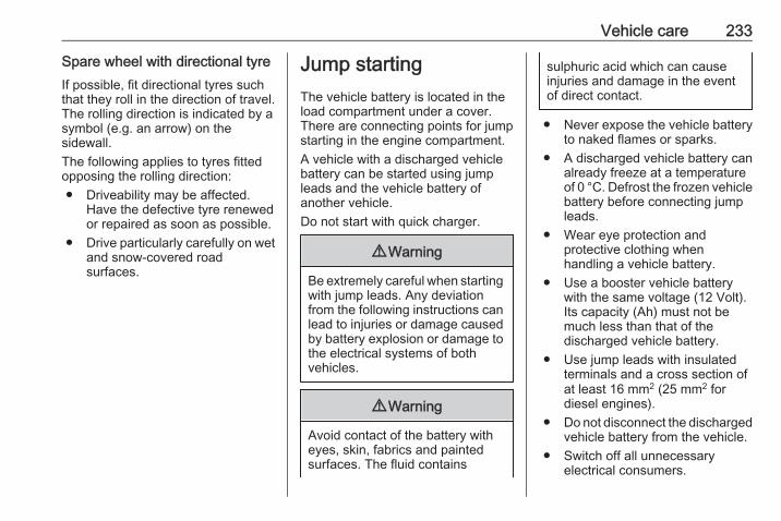
Vehicle care 233
Spare wheel with directional tyreIf possible, fit directional tyres suchthat they roll in the direction of travel.The rolling direction is indicated by asymbol (e.g. an arrow) on thesidewall.The following applies to tyres fittedopposing the rolling direction:● Driveability may be affected.
Have the defective tyre renewedor repaired as soon as possible.
● Drive particularly carefully on wetand snow-covered roadsurfaces.
Jump startingThe vehicle battery is located in theload compartment under a cover.There are connecting points for jumpstarting in the engine compartment.A vehicle with a discharged vehiclebattery can be started using jumpleads and the vehicle battery ofanother vehicle.Do not start with quick charger.
9 Warning
Be extremely careful when startingwith jump leads. Any deviationfrom the following instructions canlead to injuries or damage causedby battery explosion or damage tothe electrical systems of bothvehicles.
9 Warning
Avoid contact of the battery witheyes, skin, fabrics and paintedsurfaces. The fluid contains
sulphuric acid which can causeinjuries and damage in the eventof direct contact.
● Never expose the vehicle batteryto naked flames or sparks.
● A discharged vehicle battery canalready freeze at a temperatureof 0 °C. Defrost the frozen vehiclebattery before connecting jumpleads.
● Wear eye protection andprotective clothing whenhandling a vehicle battery.
● Use a booster vehicle batterywith the same voltage (12 Volt).Its capacity (Ah) must not bemuch less than that of thedischarged vehicle battery.
● Use jump leads with insulatedterminals and a cross section ofat least 16 mm2 (25 mm2 fordiesel engines).
● Do not disconnect the dischargedvehicle battery from the vehicle.
● Switch off all unnecessaryelectrical consumers.

234 Vehicle care
● Do not lean over the vehiclebattery during jump starting.
● Do not allow the terminals of onelead to touch those of the otherlead.
● The vehicles must not come intocontact with each other duringthe jump starting process.
● Apply the parking brake,transmission in neutral,automatic transmission in P.
● Open the positive terminalprotection cap of your vehicle inthe engine compartment and ofthe booster vehicle battery.
Lead connection order:1. Connect the red lead to the
positive terminal of the boostervehicle battery.
2. Connect the other end of the redlead to the positive terminal ofyour vehicle near the fuse box inthe engine compartment.
3. Connect the black lead to thenegative terminal of the boostervehicle battery.
4. Connect the other end of the blacklead to a vehicle grounding pointof your vehicle in the enginecompartment.
Route the leads so that they cannotcatch on rotating parts in the enginecompartment.To start the engine:1. Start the engine of the vehicle
providing the jump.2. After five minutes, start the other
engine. Start attempts should bemade for no longer than15 seconds at an interval of oneminute.
3. Allow both engines to idle forapprox. three minutes with theleads connected.
4. Switch on electrical consumers(e.g. headlights, heated rearwindow) of the vehicle receivingthe jump start.
5. Reverse above sequence exactlywhen removing leads.

Vehicle care 235
TowingTowing the vehicle
Insert a screwdriver in the slot at thelower part of the cap. Release the capby carefully moving the screwdriverdownwards.The towing eye is stowed with thevehicle tools 3 218.
Screw in the towing eye as far as it willgo until it stops in a horizontalposition.Attach a tow rope – or better still a towrod – to the towing eye.The towing eye must only be used fortowing and not for recovering thevehicle.Switch on ignition to release steeringwheel lock and to permit operation ofbrake lights, horn and windscreenwiper.Transmission in neutral.
Caution
Drive slowly. Do not drive jerkily.Excessive tractive force candamage the vehicle.
When the engine is not running,considerably more force is needed tobrake and steer.To prevent the entry of exhaust gasesfrom the towing vehicle, switch on theair recirculation and close thewindows.Vehicles with automatic transmission:The vehicle must be towed facingforwards, not faster than 80 km/h norfurther than 100 km. In all other casesand when the transmission isdefective, the front axle must beraised off the ground.Vehicles with manual transmissionautomated: the vehicle must only betowed facing forwards with the frontaxle raised off the ground.Seek the assistance of a workshop.After towing, unscrew the towing eye.Insert cap at the top and engagedownwards.

236 Vehicle care
Towing another vehicle
Insert a screwdriver in the slot at thelower bend of the cap. Release thecap by carefully moving thescrewdriver downwards.The towing eye is stowed with thevehicle tools 3 218.
Screw in the towing eye as far as it willgo until it stops in a horizontalposition.The lashing eye at the rearunderneath the vehicle must never beused as a towing eye.Attach a tow rope – or even better atow bar – to the towing eye.The towing eye must only be used fortowing and not for recovering avehicle.
Caution
Drive slowly. Do not drive jerkily.Excessive tractive force candamage the vehicle.
After towing, unscrew the towing eye.Insert cap at the top and engagedownwards.

Vehicle care 237
Appearance careExterior careLocksThe locks are lubricated at the factoryusing a high quality lock cylindergrease. Use de-icing agent only whenabsolutely necessary, as this has adegreasing effect and impairs lockfunction. After using a de-icing agent,have the locks regreased by aworkshop.
WashingThe paintwork of your vehicle isexposed to environmental influences.Wash and wax your vehicle regularly.When using automatic vehiclewashes, select a programme thatincludes waxing.Bird droppings, dead insects, resin,pollen and the like should be cleanedoff immediately, as they containaggressive constituents which cancause paint damage.
If using a vehicle wash, comply withthe vehicle wash manufacturer'sinstructions. The windscreen wiperand rear window wiper must beswitched off. Remove antenna andexternal accessories such as roofracks etc.If you wash your vehicle by hand,make sure that the insides of thewheel housings are also thoroughlyrinsed out.Clean edges and folds on openeddoors and the bonnet as well as theareas they cover.Clean bright metal mouldings with acleaning solution approved foraluminium to avoid damages.
Caution
Always use a cleaning agent witha pH value of four to nine.Do not use cleaning agents on hotsurfaces.
Do not clean the engine compartmentwith a steam-jet or high-pressure jetcleaner.
Thoroughly rinse and leather-off thevehicle. Rinse leather frequently. Useseparate leathers for painted andglass surfaces: remnants of wax onthe windows will impair vision.Have the door hinges of all doorsgreased by a workshop.Do not use hard objects to removespots of tar. Use tar removal spray onpainted surfaces.
Exterior lightsHeadlight and other light covers aremade of plastic. Do not use anyabrasive or caustic agents, do not usean ice scraper, and do not clean themdry.
Polishing and waxingWax the vehicle regularly (at thelatest when water no longer beads).Otherwise, the paintwork will dry out.Polishing is necessary only if the painthas become dull or if solid depositshave become attached to it.Paintwork polish with silicone forms aprotective film, making waxingunnecessary.

238 Vehicle care
Plastic body parts must not be treatedwith wax or polishing agents.
Windows and windscreen wiperbladesUse a soft lint-free cloth or chamoisleather together with window cleanerand insect remover.When cleaning the rear window frominside, always wipe in parallel to theheating element to prevent damage.For mechanical removal of ice, use asharp-edged ice scraper. Press thescraper firmly against the glass sothat no dirt can get under it andscratch the glass.Remove dirt residues from smearingwiper blades by using a soft cloth andwindow cleaner. Also make sure toremove any residues such as wax,insect residues and similar from thewindow.Ice residues, pollution and continuouswiping on dry windows will damage oreven destroy the wiper blades.
SunroofNever clean with solvents or abrasiveagents, fuels, aggressive media(e.g. paint cleaner, acetone-containing solutions etc.), acidic orhighly alkaline media or abrasivepads. Do not apply wax or polishingagents to the sunroof.
Wheels and tyresDo not use high-pressure jetcleaners.Clean rims with a pH-neutral wheelcleaner.Rims are painted and can be treatedwith the same agents as the body.
Paintwork damageRectify minor paintwork damage witha touch-up pen before rust forms.Have more extensive damage or rustareas repaired by a workshop.
UnderbodySome areas of the vehicle underbodyhave a PVC undercoating while othercritical areas have a durableprotective wax coating.
After the underbody is washed, checkthe underbody and have it waxed ifnecessary.Bitumen/rubber materials coulddamage the PVC coating. Haveunderbody work carried out by aworkshop.Before and after winter, wash theunderbody and have the protectivewax coating checked.
Towing equipmentDo not clean the coupling ball bar witha steam-jet or high-pressure jetcleaner.
Air shutterClean the shutter system in the frontbumper to maintain correctfunctionality.
Interior careInterior and upholsteryOnly clean the vehicle interior,including the instrument panel fasciaand panelling, with a dry cloth orinterior cleaner.

Vehicle care 239
Clean the leather upholstery withclear water and a soft cloth. In case ofheavy soiling, use leather care.The instrument cluster and thedisplays should only be cleaned usinga soft damp cloth. If necessary use aweak soap solution.Clean fabric upholstery with avacuum cleaner and brush. Removestains with an upholstery cleaner.Clothing fabrics may not becolourfast. This could cause visiblediscolourations, especially on light-coloured upholstery. Removablestains and discolourations should becleaned as soon as possible.Clean seat belts with lukewarm wateror interior cleaner.
Caution
Close Velcro fasteners as openVelcro fasteners on clothing coulddamage seat upholstery.The same applies to clothing withsharp-edged objects, like zips orbelts or studded jeans.
Plastic and rubber partsPlastic and rubber parts can becleaned with the same cleaner asused to clean the body. Use interiorcleaner if necessary. Do not use anyother agent. Avoid solvents and petrolin particular. Do not use high-pressure jet cleaners.
240 Service and maintenance
Service andmaintenance
General information ................... 240Service information .................. 240
Recommended fluids, lubricantsand parts .................................... 241
Recommended fluids andlubricants ................................ 241
General informationService informationIn order to ensure economical andsafe vehicle operation and tomaintain the value of your vehicle, itis of vital importance that allmaintenance work is carried out at theproper intervals as specified.The detailed, up-to-date serviceschedule for your vehicle is availableat the workshop.Service display 3 91.
European service intervalsMaintenance of your vehicle isrequired every 30,000 km or after oneyear, whichever occurs first, unlessotherwise indicated in the servicedisplay.A shorter service interval can be validfor severe driving behaviour, e.g. fortaxis and police vehicles.The European service intervals arevalid for the following countries:
Andorra, Austria, Belgium, Bosnia-Herzegovina, Bulgaria, Croatia,Cyprus, Czech Republic, Denmark,Estonia, Finland, France, Germany,Greece, Greenland, Hungary,Iceland, Ireland, Italy, Latvia,Liechtenstein, Lithuania,Luxembourg, Macedonia, Malta,Monaco, Montenegro, Netherlands,Norway, Poland, Portugal, Romania,San Marino, Serbia, Slovakia,Slovenia, Spain, Sweden,Switzerland, United Kingdom.Service display 3 91.
International service intervalsMaintenance of your vehicle isrequired every 15,000 km or after oneyear, whichever occurs first, unlessotherwise indicated in the servicedisplay.The international service intervals arevalid for the countries which are notlisted in the European serviceintervals.Service display 3 91.

Service and maintenance 241
ConfirmationsConfirmation of service is recorded inthe Service and warranty booklet.The date and mileage is completedwith the stamp and signature of theservicing workshop.Make sure that the Service andwarranty booklet is completedcorrectly as continuous proof ofservice is essential if any warranty orgoodwill claims are to be met, and isalso a benefit when selling thevehicle.
Service interval with remainingengine oil life durationThe service interval is based onseveral parameters depending onusage.The service display lets you knowwhen to change the engine oil.Service display 3 91.
Recommended fluids,lubricants and partsRecommended fluids andlubricantsOnly use products that meet therecommended specifications.
9 Warning
Operating materials arehazardous and could bepoisonous. Handle with care. Payattention to information given onthe containers.
Engine oilEngine oil is identified by its qualityand its viscosity. Quality is moreimportant than viscosity whenselecting which engine oil to use. Theoil quality ensures e.g. enginecleanliness, wear protection and oilaging control, whereas viscositygrade gives information on the oil'sthickness over a temperature range.
Dexos is the newest engine oil qualitythat provides optimum protection forgasoline and diesel engines. If it isunavailable, engine oils of other listedqualities have to be used.Recommendations for gasolineengines are also valid forCompressed Natural Gas (CNG),Liquified Petroleum Gas (LPG) andEthanol (E85) fuelled engines.Select the appropriate engine oilbased on its quality and on theminimum ambient temperature3 245.
Topping up engine oilEngine oils of different manufacturersand brands can be mixed as long asthey comply with the required engineoil quality and viscosity.Use of engine oil with onlyACEA A1/B1 or only A5/B5 quality isprohibited, since it can cause long-term engine damage under certainoperating conditions.Select the appropriate engine oilbased on its quality and on theminimum ambient temperature3 245.

242 Service and maintenance
Additional engine oil additivesThe use of additional engine oiladditives could cause damage andinvalidate the warranty.
Engine oil viscosity gradesThe SAE viscosity grade givesinformation of the thickness of the oil.Multigrade oil is indicated by twofigures, e.g. SAE 5W-30. The firstfigure, followed by a W, indicates thelow temperature viscosity and thesecond figure the high temperatureviscosity.Select the appropriate viscosity gradedepending on the minimum ambienttemperature 3 245.All of the recommended viscositygrades are suitable for high ambienttemperatures.
Coolant and antifreezeUse only organic acid type-long lifecoolant (LLC) antifreeze approved forthe vehicle. Consult a workshop.The system is factory filled withcoolant designed for excellentcorrosion protection and frostprotection down to approx. -28 °C. In
northern countries with very lowtemperatures the factory filled coolantprovides frost protection down toapprox. -37 °C. This concentrationshould be maintained all year round.The use of additional coolantadditives that intend to give additionalcorrosion protection or seal againstminor leaks can cause functionproblems. Liability for consequencesresulting from the use of additionalcoolant additives will be rejected.
Brake and clutch fluidOver time, brake fluid absorbsmoisture which will reduce brakingeffectiveness. The brake fluid shouldtherefore be replaced at the specifiedinterval.

Technical data 243
Technical data
Vehicle identification .................. 243Vehicle Identification Number .. 243Identification plate ................... 243Engine identification ................ 244
Vehicle data ............................... 245Recommended fluids andlubricants ................................ 245
Engine data ............................. 248Performance ............................ 250Vehicle weight ......................... 251Vehicle dimensions ................. 252Capacities ................................ 253Tyre pressures ........................ 254
Vehicle identificationVehicle IdentificationNumber
The Vehicle Identification Numbermay be stamped on the identificationplate and on the floor pan, under thefloor covering, visible under a cover.The Vehicle Identification Numbermay be embossed on the instrumentpanel, visible through the windscreen,or in the engine compartment on theright body panel.
Identification plate
The identification plate is located onthe front left or right door frame.

244 Technical data
Information on identification label:1 : manufacturer2 : type approval number3 : vehicle identification number4 : permissible gross vehicle weight
rating in kg5 : permissible gross train weight
in kg6 : maximum permissible front axle
load in kg7 : maximum permissible rear axle
load in kg8 : vehicle-specific or country-
specific data
The combined total of front and rearaxle loads must not exceed thepermissible gross vehicle weight. Forexample, if the front axle is bearing itsmaximum permissible load, the rearaxle can only bear a load that is equalto the gross vehicle weight minus thefront axle load.The technical data is determined inaccordance with EuropeanCommunity standards. We reservethe right to make modifications.Specifications in the vehicledocuments always have priority overthose given in this manual.
Engine identificationThe technical data tables show theengine identifier code. Engine data3 248.To identify the respective engine,refer to the engine power in the EECCertificate of Conformity providedwith your vehicle or other nationalregistration documents.

Technical data 245
Vehicle dataRecommended fluids and lubricantsEuropean service schedule
Required engine oil qualityAll European countries with European service interval 3 240
Engine oil quality Petrol engines(including CNG, LPG, E85)
Diesel engines
dexos 1 – –
dexos 2 ✔ ✔
In case dexos quality is unavailable you may use max. one litre engine oil quality ACEA C3 once between each oil change.
Engine oil viscosity gradesAll European countries with European service interval 3 240
Ambient temperature Petrol and diesel engines
down to -25 °C SAE 5W-30 or SAE 5W-40
below -25 °C SAE 0W-30 or SAE 0W-40

246 Technical data
International service schedule
Required engine oil qualityAll countries with international service interval 3 240
Engine oil quality Petrol engines(including CNG, LPG, E85)
Diesel engines
dexos 1 (if available) ✔ –
dexos 2 ✔ ✔
In case dexos quality is unavailable you may use the oil qualities listed below:
All countries with international service interval 3 240
Engine oil quality Petrol engines(including CNG, LPG, E85)
Diesel engines
GM-LL-A-025 ✔ –
GM-LL-B-025 – ✔
All countries with international service interval 3 240
Engine oil quality Petrol engines(including CNG, LPG, E85)
Diesel engines
ACEA A3/B3 ✔ –
ACEA A3/B4 ✔ ✔

Technical data 247
All countries with international service interval 3 240
ACEA C3 ✔ ✔
API SM ✔ –
API SN resource conserving ✔ –
Engine oil viscosity gradesAll countries with international service interval 3 240
Ambient temperature Petrol and diesel engines
down to -25 °C SAE 5W-30 or SAE 5W-40
below -25 °C SAE 0W-30 or SAE 0W-40
down to -20 °C SAE 10W-301) or SAE 10W-401)
1) Permitted, but usage of SAE 5W-30 or SAE 5W-40 with dexos quality is recommended.

248 Technical data
Engine dataSales designation 1.0 1.4 1.4 1.4 1.6Engine identifier code B10XFL B14XE B14XFL B14XFT B16SHT
Number of cylinders 3 4 4 4 4
Piston displacement [cm3] 999 1399 1399 1399 1598
Engine power [kW] 77 74 92 110 147
at rpm 5500 6000 4000-5600 5000-5600 4700-5500
Torque [Nm] 170 130 245/2302) 245/2302) 300
at rpm 1800-4250 4400 2000-3500 2000-4000 1700-4700
Fuel type Petrol Petrol Petrol Petrol Petrol
Octane rating RON
recommended 95 95 95 95 98
possible 98 98 98 98 95
possible 91 91 91 91 91
Gas – – – – –
Engine oil consumption [l/1000 km]3) 0.6 0.6 0.6 0.6 0.6
2) With Stop-start system.3) Maximum value.

Technical data 249
Sales designation 1.6 1.6 1.61.6 1.6Engine identifier code B16DTC B16DTE B16DTHB16DTR B16DTU
Number of cylinders 4 4 44 4
Piston displacement [cm3] 1598 1598 15981598 1598
Engine power [kW] 70 81 100117 81
at rpm 3500 3500 3500-40004000 3500
Torque [Nm] 280 300 320350 300
at rpm 1500-1750 1750-2000 2000-22501500-2250 1750-2000
Fuel type Diesel Diesel DieselDiesel Diesel
Engine oil consumption [l/1000 km]4) 0.6 0.6 0.60.6 0.6
4) Maximum value.

250 Technical data
PerformanceEngine B10XFL B14XE B14XFL B14XFT B16SHT
Maximum speed [km/h]
Manual transmission 194 –5) 2046)/199 2166)/210 –5)
Manual transmission automated 198 – – – –
Automatic transmission – – – – –
5) Value was not available at time of printing.6) With Stop-start system.
Engine B16DTC B16DTE B16DTH B16DTR B16DTU
Maximum speed [km/h]
Manual transmission 181 192 207 –5) –5)
Manual transmission automated – – – – –
Automatic transmission – – 198 – –
5) Value was not available at time of printing.

Technical data 251
Vehicle weightKerb weight, basic model without any optional equipment
5-door hatchback Engine Manual transmission Manual transmission automated Automatic transmission
without/with air conditioning[kg]
B10XFL 1263/1273 1263/1273 –
B14XE –7) – –
B14XFL –/1278 – –
B14XFT –/1278 – –
B16SHT –7) – –
B16DTC 1335/1345 – –
B16DTE 1350/1360 – –
B16DTH 1350/1360 – –/1364
B16DTR –7) – –
B16DTU –7) – –
7) Value was not available at time of printing.
Optional equipment and accessories increase the kerb weight.Loading information 3 73.

252 Technical data
Vehicle dimensions5-door hatchback
Length [mm] 4370
Width without exterior mirrors [mm] 1809
Width with two exterior mirrors [mm] 2042
Height (without antenna) [mm] 1500
Length of load compartment floor [mm] 828
Length of load compartment with folded rear seats [mm] 1575
Load compartment width [mm] 1001
Load compartment height [mm] 588
Wheelbase [mm] 2662
Turning circle diameter [m] 11.44

Technical data 253
CapacitiesEngine oil
Engine B10XFL B14XFL,B14XFT
B16DTH,B16DTC,B16DTE
B14XE,B16SHT,B16DTR,B16DTU
including Filter [l] 4.0 4.5 5.0 –8)
between MIN and MAX [l] 1.0 1.0 1.0 –8)
8) Value was not available at time of printing.
Fuel tank
Petrol/diesel, refilling quantity [l] 48

254 Technical data
Tyre pressures5-door hatchback Comfort with up to 3 people ECO with up to 3 people With full loadEngine Tyres front rear front rear front rear
[kPa/bar]([psi])
[kPa/bar]([psi])
[kPa/bar]([psi])
[kPa/bar]([psi])
[kPa/bar]([psi])
[kPa/bar]([psi])
B10XFL,B14XE
195/65 R15,225/45 R17
220/2.2 (32) 220/2.2 (32) 270/2.7 (39) 270/2.7 (39) 250/2.5 (36) 270/2.7 (39)
205/55 R16 220/2.2 (32) 220/2.2 (32) 300/3.0 (43) 300/3.0 (43) 250/2.5 (36) 270/2.7 (39)
B14XFL 195/65 R15,225/45 R17,225/40 R18
220/2.2 (32) 220/2.2 (32) 270/2.7 (39) 270/2.7 (39) 250/2.5 (36) 270/2.7 (39)
205/55 R16 220/2.2 (32) 220/2.2 (32) 300/3.0 (43) 300/3.0 (43) 250/2.5 (36) 270/2.7 (39)
B14XFT 195/65 R15,225/45 R17,215/55 R16,215/50 R17,225/40 R18
220/2.2 (32) 220/2.2 (32) 270/2.7 (39) 270/2.7 (39) 250/2.5 (36) 270/2.7 (39)
205/55 R16 220/2.2 (32) 220/2.2 (32) 300/3.0 (43) 300/3.0 (43) 250/2.5 (36) 270/2.7 (39)

Technical data 255
5-door hatchback Comfort with up to 3 people ECO with up to 3 people With full loadEngine Tyres front rear front rear front rear
[kPa/bar]([psi])
[kPa/bar]([psi])
[kPa/bar]([psi])
[kPa/bar]([psi])
[kPa/bar]([psi])
[kPa/bar]([psi])
B16DTE,B16DTH
225/45 R17,225/40 R18
240/2.4 (35) 220/2.2 (32) 270/2.7 (39) 270/2.7 (39) 250/2.5 (36) 270/2.7 (39)
205/55 R16 240/2.4 (35) 220/2.2 (32) 300/3.0 (43) 300/3.0 (43) 250/2.5 (36) 270/2.7 (39)
B16DTR,B16SHT
225/45 R17 240/2.4 (35) 220/2.2 (32) 270/2.7 (39) 270/2.7 (39) 250/2.5 (36) 270/2.7 (39)
225/40 R18 260/2.6 (38) 240/2.4 (35) 270/2.7 (39) 270/2.7 (39) 270/2.7 (39) 290/2.9 (42)
205/55 R16 240/2.4 (35) 220/2.2 (32) 300/3.0 (43) 300/3.0 (43) 250/2.5 (36) 270/2.7 (39)
B16DTC,B16DTU
195/65 R15,225/45 R17
240/2.4 (35) 220/2.2 (32) 270/2.7 (39) 270/2.7 (39) 250/2.5 (36) 270/2.7 (39)
205/55 R16 240/2.4 (35) 220/2.2 (32) 300/3.0 (43) 300/3.0 (43) 250/2.5 (36) 270/2.7 (39)
All Temporary sparewheel115/70 R16
420/4.2 (60) 420/4.2 (60) – – 420/4.2 (60) 420/4.2 (60)

256 Customer information
Customerinformation
Customer information ................ 256Declaration of conformity ......... 256Collision damage repair ........... 258Software acknowledgement .... 258
Vehicle data recording and pri‐vacy ........................................... 260
Event data recorders ............... 260Radio Frequency Identification(RFID) ..................................... 261
Customer informationDeclaration of conformityRadio transmission systemsThis vehicle has systems thattransmit and/or receive radio wavessubject to Directive 1999/5/EC.These systems are in compliancewith the essential requirements andother relevant provisions ofDirective 1999/5/EC. Copies of theoriginal Declarations of Conformitycan be obtained on our website.

Customer information 257
Jack

258 Customer information
Translation of the original declarationof conformityDeclaration of conformity accordingto EC Directive 2006/42/ECWe declare that the product:Product designation: JackType/GM part number: 13590035is in compliance with the provisions ofDirective 2006/42/EC.Applied technical standards:GMN9737 : jackingGM 14337 : standard equipment
jack – hardwaretests
GMN5127 : vehicle integrity –hoisting and servicestation jacking
GMW15005 : standard equipmentjack and spare tyre,vehicle test
ISO TS 16949 : qualitymanagementsystems
The signatory is authorised tocompile the technical documentation.Rüsselsheim, 27th May 2015signed byAndré-Alexander KonterEngineering Group Manager Tyreand Wheel SystemsAdam Opel AGD-65423 Rüsselsheim
Collision damage repairPaint thicknessDue to production, the thickness ofthe paint can differ between 50 and400 µm.Therefore, different paint thickness isno indicator for a collision damagerepair.
Software acknowledgementCertain OnStar components includelibcurl and unzip software and otherthird party software. Below are thenotices and licenses associated withlibcurl and unzip and for other thirdparty software please see http://www.lg.com/global/support/opensource/index.
libcurlCopyright and permission noticeCopyright (c) 1996 - 2010, DanielStenberg, <[email protected]>.All rights reserved.Permission to use, copy, modify, anddistribute this software for anypurpose with or without fee is herebygranted, provided that the abovecopyright notice and this permissionnotice appear in all copies.The software is provided "as is",without warranty of any kind, expressor implied, including but not limited tothe warranties of merchantability,fitness for a particular purpose andnoninfringement of third party rights.In no event shall the authors or

Customer information 259
copyright holders be liable for anyclaim, damages or other liability,whether in an action of contract, tortor otherwise, arising from, out of or inconnection with the software or theuse or other dealings in the software.Except as contained in this notice, thename of a copyright holder shall notbe used in advertising or otherwise topromote the sale, use or otherdealings in this Software without priorwritten authorization of the copyrightholder.
unzipThis is version 2005-Feb-10 of theInfo-ZIP copyright and license. Thedefinitive version of this documentshould be available at ftp://ftp.info-zip.org/pub/infozip/license.htmlindefinitely.Copyright (c) 1990-2005 Info-ZIP. Allrights reserved.For the purposes of this copyright andlicense, “Info-ZIP” is defined as thefollowing set of individuals:Mark Adler, John Bush, Karl Davis,Harald Denker, Jean-Michel Dubois,Jean-loup Gailly, Hunter Goatley, Ed
Gordon, Ian Gorman, Chris Herborth,Dirk Haase, Greg Hartwig, RobertHeath, Jonathan Hudson, PaulKienitz, David Kirschbaum, JohnnyLee, Onno van der Linden, IgorMandrichenko, Steve P. Miller, SergioMonesi, Keith Owens, GeorgePetrov, Greg Roelofs, Kai UweRommel, Steve Salisbury, DaveSmith, Steven M. Schweda, ChristianSpieler, Cosmin Truta, AntoineVerheijen, Paul von Behren, RichWales, Mike White.This software is provided “as is,”without warranty of any kind, expressor implied. In no event shall Info-ZIPor its contributors be held liable forany direct, indirect, incidental, specialor consequential damages arising outof the use of or inability to use thissoftware.Permission is granted to anyone touse this software for any purpose,including commercial applications,and to alter it and redistribute it freely,subject to the following restrictions:
1. Redistributions of source codemust retain the above copyrightnotice, definition, disclaimer, andthis list of conditions.
2. Redistributions in binary form(compiled executables) mustreproduce the above copyrightnotice, definition, disclaimer, andthis list of conditions indocumentation and/or othermaterials provided with thedistribution. The sole exception tothis condition is redistribution of astandard UnZipSFX binary(including SFXWiz) as part of aself-extracting archive; that ispermitted without inclusion of thislicense, as long as the normalSFX banner has not beenremoved from the binary ordisabled.
3. Altered versions--including, butnot limited to, ports to newoperating systems, existing portswith new graphical interfaces, anddynamic, shared, or static libraryversions--must be plainly markedas such and must not bemisrepresented as being the

260 Customer information
original source. Such alteredversions also must not bemisrepresented as being Info-ZIPreleases--including, but notlimited to, labeling of the alteredversions with the names “Info-ZIP” (or any variation thereof,including, but not limited to,different capitalizations), “PocketUnZip,” “WiZ” or “MacZip” withoutthe explicit permission of Info-ZIP.Such altered versions are furtherprohibited from misrepresentativeuse of the Zip-Bugs or Info-ZIP e-mail addresses or of the Info-ZIPURL(s).
4. Info-ZIP retains the right to usethe names “Info-ZIP,” “Zip,”“UnZip,” “UnZipSFX,” “WiZ,”“Pocket UnZip,” “Pocket Zip,” and“MacZip” for its own source andbinary releases.
Vehicle data recordingand privacyEvent data recordersData storage modules in thevehicleA large number of electroniccomponents of your vehicle containdata storage modules temporarily orpermanently storing technical dataabout the condition of the vehicle,events and errors. In general, thistechnical information documents thecondition of parts, modules, systemsor the environment:● operating conditions of system
components (e.g. filling levels)● status messages of the vehicle
and its single components (e.g.number of wheel revolutions /rotational speed, deceleration,lateral acceleration)
● dysfunctions and defects inimportant system components
● vehicle reactions in particulardriving situations (e.g. inflation ofan airbag, activation of thestability regulation system)
● environmental conditions (e.g.temperature)
These data are exclusively technicaland help identifying and correctingerrors as well as optimising vehiclefunctions.Motion profiles indicating travelledroutes cannot be created with thesedata.If services are used (e.g. repairworks, service processes, warrantycases, quality assurance),employees of the service network(manufacturer included) are able toread out this technical informationfrom the event and error data storagemodules applying special diagnosticdevices. If required, you will receivefurther information at theseworkshops. After an error has beencorrected, the data are deleted fromthe error storage module or they areconstantly overwritten.

Customer information 261
When using the vehicle, situationsmay occur in which these technicaldata related to other information(accident report, damages on thevehicle, witness statements etc.) maybe associated with a specific person -possibly, with the assistance of anexpert.Additional functions contractuallyagreed upon with the client (e.g.vehicle location in emergency cases)allow the transmission of particularvehicle data from the vehicle.
Radio FrequencyIdentification (RFID)RFID technology is used in somevehicles for functions such as tyrepressure monitoring and ignitionsystem security. It is also used inconnection with conveniences suchas radio remote controls for doorlocking/unlocking and starting, and in-vehicle transmitters for garage dooropeners. RFID technology in Opelvehicles does not use or recordpersonal information or link with anyother Opel system containingpersonal information.

262
Index AAccessories and vehicle
modifications .......................... 195Active emergency braking.......... 170Adjustable air vents ................... 137Airbag and belt tensioners ........... 93Airbag deactivation ................ 57, 93Airbag label................................... 53Airbag system .............................. 53Air conditioning regular
operation ................................ 138Air conditioning system .............. 130Air intake .................................... 138Air vents...................................... 137Antilock brake system ................ 157Antilock brake system (ABS) ....... 95Anti-theft alarm system ................ 31Anti-theft locking system .............. 31Appearance care........................ 237Armrest................................... 48, 50Armrest storage ........................... 67Ashtrays ....................................... 84Automatic anti-dazzle .................. 36Automatic light control ............... 119Automatic locking ........................ 28Automatic transmission ............. 151Auxiliary heater........................... 137
BBattery discharge protection ...... 128Battery voltage ........................... 107Belts.............................................. 50Bonnet ....................................... 197Brake and clutch fluid................. 241Brake and clutch system ............. 94Brake assist ............................... 160Brake fluid .................................. 200Brakes ............................... 157, 200Breakdown.................................. 235Bulb replacement ....................... 203
CCapacities .................................. 253Catalytic converter ..................... 150Central locking system ................ 24Centre console lighting .............. 127Changing tyre and wheel size . . . 225Charging system .......................... 93Child locks ................................... 29Child restraint installation
locations ................................... 62Child restraints.............................. 59Child restraint systems ................ 59Climate control ............................. 16Climate control systems............. 129Clock............................................. 80Collision damage repair.............. 258Control indicators.......................... 92

263
Control of the vehicle ................. 140Controls........................................ 76Convex shape .............................. 34Coolant and antifreeze............... 241Cruise control ...................... 97, 163Cupholders .................................. 66Curtain airbag system .................. 57Curve lighting.............................. 120
DDanger, Warnings and Cautions . . . 4Daytime running lights ............... 120Declaration of conformity............ 256Diesel fuel system bleeding ....... 202Diesel particle filter .................... 149Door open .................................... 98Doors............................................ 30Driver assistance systems.......... 163Driver Information Centre............. 98Driving characteristics and
towing tips .............................. 191Driving hints................................ 140
EElectric adjustment ...................... 34Electrical system......................... 211Electric parking brake........... 94, 158Electric parking brake fault........... 94Electronic climate control system 132Electronic driving programmes .
........................................ 153, 157
Electronic key system................... 22Electronic Stability Control.......... 161Electronic Stability Control and
Traction Control system............ 95Electronic Stability Control off....... 95End-of-life vehicle recovery ....... 196Engine compartment fuse box ... 212Engine coolant ........................... 199Engine coolant temperature
gauge ....................................... 90Engine data ............................... 248Engine exhaust .......................... 149Engine identification................... 244Engine oil ................... 198, 241, 245Engine oil pressure ...................... 96Entry lighting .............................. 127Event data recorders.................. 260Exit lighting ................................ 127Exterior care .............................. 237Exterior light ................................. 97Exterior lighting .................... 13, 118Exterior mirrors............................. 34
FFault ................................... 153, 157First aid kit ................................... 72Fixed air vents ........................... 137Fog light ....................................... 97Fog lights ................................... 205Folding mirrors ............................. 35
Following distance........................ 95Following distance indication...... 169Forward collision alert................. 167Fragrance diffuser........................ 83Front airbag system ..................... 56Front fog lights ........................... 124Front seats.................................... 42Front storage................................ 67Fuel............................................. 188Fuel consumption - CO2-
Emissions ............................... 190Fuel for diesel engines .............. 188Fuel for petrol engines ............... 188Fuel gauge ................................... 90Fuses ......................................... 211
GGauges......................................... 88Gear shifting................................. 95General information ................... 191Glovebox ..................................... 66
HHalogen headlights .................... 203Hand brake......................... 157, 158Hazard warning flashers ............ 123Headlight flash ........................... 119Headlight range adjustment ...... 119Headlights................................... 118Headlights when driving abroad 120Head restraint adjustment ............. 8

264
Head restraints ............................ 41Heated mirrors ............................. 35Heated rear window ..................... 39Heated steering wheel ................. 77Heating .................................. 48, 50Heating and ventilation system . 129High beam ........................... 97, 119High beam assist.......................... 97Hill start assist ........................... 160Horn ....................................... 14, 77
IIdentification plate ..................... 243Ignition switch positions ............. 140Immobiliser ............................ 34, 97Indicators...................................... 88Info display................................. 103Information displays...................... 98Instrument cluster ........................ 85Instrument panel fuse box ......... 214Instrument panel illumination ..... 211Instrument panel illumination
control .................................... 126Instrument panel overview ........... 10Interior care ............................... 238Interior lighting............................ 126Interior lights ...................... 126, 211Interior mirrors.............................. 36Interruption of power supply ...... 153Introduction .................................... 3
JJump starting ............................. 233
KKey, memorised settings.............. 24Keys ............................................. 20Keys, locks................................... 20
LLane keep assist.................. 95, 186Lashing eyes ............................... 71LED headlights..................... 97, 120Lighting features......................... 127Light switch ................................ 118Load compartment ................ 30, 68Load compartment cover ............. 70Load compartment fuse box ...... 216Loading information ..................... 73Low fuel ....................................... 96
MMalfunction indicator light ............ 94Manual anti-dazzle ...................... 36Manual mode ..................... 152, 156Manual seat adjustment............... 43Manual transmission .................. 154Manual transmission automated 155Manual windows .......................... 37Massage....................................... 49Maximum speed......................... 219Memorised settings...................... 24
Mirror adjustment ........................... 9Misted light covers ..................... 125
NNew vehicle running-in .............. 140Number plate light ..................... 210
OObject detection systems........... 171Odometer ..................................... 89Oil, engine.......................... 241, 245OnStar® system......................... 114Outside temperature .................... 80Overrun cut-off ........................... 145
PParking ................................ 19, 148Parking assist ............................ 171Parking brake ............................ 158Parking lights ............................. 125Particulate filter........................... 149Performance .............................. 250Performing work ........................ 197Pollen filter ................................. 138Power button.............................. 141Power connector........................... 83Power outlets ............................... 82Power seat adjustment ................ 45Power windows ............................ 37Preheating ................................... 96Puncture..................................... 228

265
QQuickheat................................... 137
RRadio Frequency Identification
(RFID)..................................... 261Radio remote control ................... 21Reading lights ............................ 126Rear floor storage cover .............. 71Rear fog light ....................... 97, 125Rear seats.................................... 50Rear view camera ...................... 180Rear window wiper/washer .......... 79Recommended fluids and
lubricants ........................ 241, 245Refuelling ................................... 189Retained power off..................... 142Reversing lights ......................... 125Ride control systems.................. 160Roof.............................................. 39Roof load...................................... 73Roof rack ..................................... 73
SSafety belts................................... 50Seat adjustment ............................. 7Seat belt ........................................ 8Seat belt reminder ....................... 92Seat belts ..................................... 50
Seat heatingSeat heating, front..................... 48Seat heating, rear..................... 50
Seat position ................................ 42Selector lever ..................... 151, 155Service ............................... 138, 240Service display ............................ 91Service information .................... 240Side airbag system ...................... 56Side blind spot alert.................... 179Sidelights.................................... 118Side turn signal lights ................ 209Software acknowledgement....... 258Spare wheel ............................... 231Speed limiter......................... 97, 165Speedometer ............................... 88Sport mode ................................ 163Starting and operating................ 140Starting off ................................... 17Starting the engine .................... 143Steering...................................... 140Steering wheel adjustment ...... 9, 76Steering wheel controls ............... 76Stop-start system........................ 145Storage......................................... 66Storage compartments................. 66Sunroof ........................................ 39Sunvisor lights ........................... 127Sun visors .................................... 39Symbols ......................................... 4
TTachometer ................................. 90Tail lights ................................... 206Three-point seat belt .................... 51Tools .......................................... 218Tow bar....................................... 191Towing................................ 191, 235Towing another vehicle ............. 236Towing equipment ..................... 192Towing the vehicle ..................... 235Traction Control system ............. 160Traction Control system off........... 96Traffic sign assistant............. 98, 182Trailer coupling........................... 191Trailer stability assist ................. 194Trailer towing ............................. 191Transmission ............................... 16Transmission display ......... 151, 155Tread depth ............................... 224Trip odometer .............................. 89Turn and lane-change signals ... 124Turn signal ................................... 92Tyre chains ................................ 225Tyre designations ...................... 219Tyre pressure ............................ 219Tyre pressure monitoring
system............................... 96, 220Tyre pressures ........................... 254Tyre repair kit ............................. 225
266
UUltrasonic parking assist............. 171Upholstery.................................. 238Using this manual .......................... 3
VValet mode................................. 103Vehicle battery ........................... 201Vehicle checks............................ 197Vehicle data................................ 245Vehicle data recording and
privacy..................................... 260Vehicle detected ahead................ 97Vehicle dimensions .................... 252Vehicle Identification Number .... 243Vehicle jack................................ 218Vehicle messages ..................... 105Vehicle personalisation ............. 107Vehicle security............................ 31Vehicle specific data ...................... 3Vehicle storage........................... 196Vehicle tools............................... 218Vehicle unlocking ........................... 6Vehicle weight ........................... 251Ventilating..................................... 49Ventilation................................... 129
WWarning chimes ......................... 106Warning lights............................... 88Warning triangle .......................... 72
Washer and wiper systems ......... 14Washer fluid ............................... 200Wheel changing ......................... 228Wheel covers ............................. 225Wheels and tyres ....................... 218Windows....................................... 36Windscreen................................... 36Windscreen wiper/washer ........... 77Winter tyres ............................... 218Wiper blade replacement .......... 203

www.opel.com
Copyright by ADAM OPEL AG, Rüsselsheim, Germany.
The information contained in this publication is effective as of the date indicated below. Adam Opel AG reserves the right to make changes to the technical specifications, features anddesign of the vehicles relative to the information in this publication as well as changes to the publication itself.
Edition: August 2015, ADAM OPEL AG, Rüsselsheim.
Printed on chlorine-free bleached paper.
08/2015
*KTA-2775/1-EN*
KTA-2775/1-en