oo-h method: extending uml to model web interfaces
TRANSCRIPT

144 Gómez & Cachero
Chapter VIII
OO-H Method:Extending UML to Model
Web InterfacesJaime Gómez
The Web Engineering Research Group, University of Alicante, Spain
Cristina CacheroThe Web Engineering Research Group, University of Alicante, Spain
Copyright © 2003, Idea Group, Inc.
ABSTRACTThe mostly “creative” authoring process used to develop many Webapplications during the last years has already proven unsuccessful totackle, with its increasing complexity, both in terms of user and technicalrequirements. This fact has nurtured a mushrooming of proposals, mostbased on conceptual models, that aim at facilitating the development,maintenance and assessment of Web applications, thus improving thereliability of the Web development process.In this chapter, we will show how traditional software engineeringapproaches can be extended to deal with the Web idiosyncrasy, takingadvantage of proven successful notation and techniques for commontasks, while adding models and constructs needed to capture the nuancesof the Web environment. In this context, our proposal, the Object-Oriented Hypermedia (OO-H) Method, developed at University of Alicante,provides a set of new views that extend UML to provide a Web interfacemodel. A code generation process is able to, departing from such diagrams

OO-H Method: Extending UML to Model Web Interfaces 145
and their associated tagged values, generate a Web interface capable ofconnecting to underlying business modules.
INTRODUCTIONIn the last few years, we have witnessed how existing and to come Web
technologies have induced much more flexible distributed environments wherenew business opportunities have appeared but also new risks related tosoftware development (Murugesan et al., 1999). Although the scientificcommunity agrees that in order to keep the possibility of failure to a minimum,the development process for enterprise applications should evolve in a Webengineering manner, there is no agreement at how the core activities behind asound Web application development process should be addressed. Someapproaches, most coming from the hypermedia community, consider Webapplications as information delivery systems, where only trivial functionality isoffered (Mecca, Merialdo, & Atzeni, 1999; Schwabe & Almeida, 1999; Ceriet al., 2000). Others, mainly coming from the traditional Software Engineeringfield, regard Web applications as traditional distributed applications, andpropose modeling approaches that make exclusive use of standard models andnotation to capture the idiosyncrasy of this new platform (Conallen, 1999). Stillother approaches consider the Web as a dynamic business Web (GartnerGroup, Inc., 2001), where the application development consists of a processof communication and integration of Web services disseminated over the netand offered via (often) collaborating technologies such as UDDI (UniversalDescription, Discovery and Integration, 2001), DSML (Directory ServicesMarkup Language, 2001), SOAP (Simple Object Access Protocol, 2001) orWSDL (Web Services Description Language, 2001).
We agree with Manola (1999), in that each of these trends partiallyaddresses the nuances Web applications involve, and so a fusion of theirrespective points of view is needed in order to provide a cohesive solution tothe Web application modeling process. On one hand, hypermedia modelingmethods contribute a deep reflection on Web navigation and interaction issues,which are basic for a Web application to succeed. However, these soundnavigation features are not enough, as Web applications must also provide theuser with the (often complex) functionality they need, far beyond navigation.The modeling of functional requirements has already been partially addressedin a number of Advanced Software Production Environments, many based onthe UML (UML Specification. V1.3., 1999) notation, that use Model BasedCode Generation techniques (Bell, 1998) and have the support of “traditional”software engineering methods. The problem is that those traditional models,
146 Gómez & Cachero
methods and notations do not provide the mechanisms, models and constructsneeded to capture the specific hypermedia semantics, and so are too cumber-some when used in isolation. Furthermore, functionality may be centered on asingle server or be distributed over the Web, and it is here where the conceptof dynamic business Web plays an important role: proposed models should becapable of abstracting the implementation issues far beyond the concept ofclient–server applications: the integration of services is a must in the to-comeSemantic Web (Semantic Web, 2001), but existing proposals (User InterfaceModeling Language, 2001; Gellersen & Gaedke, 1999) are still, from our pointof view, too close to the solution space.
Our approach, known as the OO-H (Object-Oriented Hypermedia)method (Gómez, Cachero, & Pastor, 2001), centers on the authoring process(product development phase). It follows this “integrating” philosophy andextends traditional software engineering approaches (based on UML) with twonew models, namely, (1) a navigation model and (2) a presentation model(further divided into an abstract presentation layer and a layout compositionlayer). The navigation model is built up departing from a UML-compliant use-case and a business class diagram. Use cases provide OO-H with the user-centered perspective which we think is necessary in Web environments, whilethe class diagram is a suitable mechanism not only to show the domainconceptual model but also to expose the interfaces that permit the connectionwith preexistent business logic modules, no matter where they are located orits internal nature (Web services, dll’s, javaBeans, etc.). In the implementationphase, tagged values associated with these interfaces determine their natureand the most suitable access protocol to actually invoke the services andrecover the return values. The process is iterative and incremental (as suggeststhe idiosyncrasy of Web applications1), and in each iteration, a refined versionof the application is generated.
Special features, particular to any kind of Web application (including e-commerce applications), are addressed by means of frameworks and patternsthat are gathered in an OO-H pattern catalog. Patterns capture practicesproven successful to solve a given problem under different circumstances. Thepattern mechanism allows the encapsulation of Web design knowledge andfacilitates reuse. The OO-H case tool allows the addition of such patterns andframeworks in a dynamic way. Its use speeds up the development processwhile isolating the designer from implementation issues, likely to change in sucha dynamic environment as the Web. Therefore, the designer is allowed to focuson more abstract features such as service chains, user profiles, usabilityfeatures, and so on. The use of patterns is further discussed in section “ViewRefinement: Presentation Modeling”.
OO-H Method: Extending UML to Model Web Interfaces 147
Departing from the navigation model, a default abstract presentationmodel can be obtained in an automatic way. This abstract presentation modelis composed of a set of XML templates that gathers the orthogonal views OO-H takes into account when dealing with Web interfaces, and which are, namely,structure, user interaction, navigation, client logic, page composition, layout,external references and connection details with underlying business modules.The designer can perform further refinements (editing the XML files or applyingpatterns from the pattern catalogue) on this default specification to get thedesired final interface appearance and behavior.
The remaining of the chapter is structured as follows: Section 2 gives abrief overview of the OO-H models and constructs that provide the neededhypermedia semantics and describes in detail, by means of a comprehensiveexample, the modeling process. Section 3 presents a discussion about relatedwork in the field. Last, conclusions and further work are sketched in Section4.
THE OBJECT-ORIENTED HYPERMEDIAMETHOD
A Brief Introduction
The OO-H (Object-Oriented Hypermedia) method is a generic model,based on the object-oriented paradigm, that provides the designer with thesemantics and notation necessary for the development of Web-based inter-faces and its connection with previously existing application logic modules.
OO-H defines a set of diagrams, techniques and tools that shape a soundapproach to the modeling of Web interfaces. The OO-H proposal includes:• Design process• Pattern catalog• Navigation access diagram (NAD)• Two-fold presentation layer (abstract presentation diagram and compos-
ite layout diagram)• CASE tool that supports and automates to a certain extent the develop-
ment process
The extension to “traditional software” production environments is achievedby means of two complementary views: (1) the navigational access diagram(NAD) that defines a navigation view, and (2) the abstract presentationdiagram (APD) and composite layout diagram (CLD) that gather the concepts
148 Gómez & Cachero
related to abstract structure of the site and specific presentation details,respectively. The NAD diagram enriches the domain view provided by theUML use case and class diagrams (UML Specification. V1.3., 1999) withnavigation and interaction features. Also, to define navigation and visualizationconstraints, OO-H uses the object constraint language (Warmer & Kleppe,1998), a subset of the standard UML that allows software developers to writeconstraints over object models augmenting the model precision. OO-H asso-ciates such constraints to the navigation model by means of filters defined uponlinks. On the other hand, the definition of abstract pages in the APD is basedon a set of XML DTDs. Both the NAD and the APD capture the interface-related design information with the aid of a set of patterns, defined in aninterface pattern catalog that is integrated in the OO-H proposal.
The Navigation Access DiagramThe navigation model is captured by means of one or more NADs. The
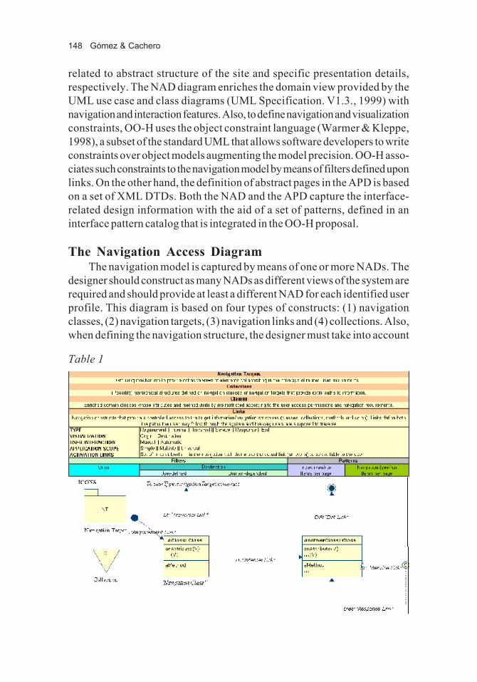
designer should construct as many NADs as different views of the system arerequired and should provide at least a different NAD for each identified userprofile. This diagram is based on four types of constructs: (1) navigationclasses, (2) navigation targets, (3) navigation links and (4) collections. Also,when defining the navigation structure, the designer must take into account
Table 1

OO-H Method: Extending UML to Model Web Interfaces 149
some orthogonal aspects such as the desired navigation behavior, the objectpopulation selection, the order in which objects should be navigated or thecardinality of the access. These features are captured by means of differentkinds of navigation patterns and filters associated with links and collections.Table 1 shows an overview of the main NAD constructs.• Navigation classes (NC): These are enriched domain classes with
attribute and method visibility that has been restricted according to theuser access permissions and navigation requirements. A sample enrich-ment is the differentiation among three types of attributes: V-attributes(visible attributes), R-attributes (referenced attributes, which are dis-played after a user demand) and H-attributes (hidden attributes, onlydisplayed when an exhaustive system population view is required, e.g., forcode refinement reasons).
• Navigation targets (NT): They group the elements of the model thatcollaborate in the coverage of each user navigation requirement.
• Navigation links (NL): They define the navigation paths the user is ableto follow through the system. They may have a navigation pattern and a setof navigation filters associated, which together provide the requiredadditional information to construct the user navigation model. OO-Hdefines six link types:o I-links (internal links) define the navigation path inside the bound-
aries of a given NT.o T-links (traversal links) are defined between navigation classes
belonging to different NT.o R-links (requirement links) point at the starting navigation point
inside each NT.o X-links (exit links) point at places outside the boundaries of the
application. They are also used as an auxiliary mechanism to repre-sent the feeding of parameters to methods.
o S-links (service links) and their corresponding R-links (responselinks) show the services available to the user type associated withthat NAD and the view the user accesses when the interface recoversthe control of the application. Service links also gather the way theuser is required to introduce the parameters needed for the invoca-tion of any method. Regarding such parameter introduction, OO-Hdefines five possibilities: (1) hidden and (2) constant parametersimply no user introduction of values. By default, the introductionmode is set to (3) immediate, which means that the interface showsa text field where the user must type the required value. When theuser is allowed to choose among a predefined set of possibilities, the

150 Gómez & Cachero
introduction mode is set to (4) selection. Last, when the parameterselection requires navigation, the (5) navigation mode (with a startnavigation link and an end navigation link, chosen among thosedefined in any NAD) is established for that parameter.
• Collections: They are (possibly) hierarchical structures defined onnavigation classes or navigation targets. They provide the user with newways of accessing the information. The most common type of collection,and the one we will use along this paper, is the C-collection (classifiercollection) that acts as an abstraction mechanism for the menu concept.
Regarding navigation filters, we have already mentioned that they arecaptured in OO-H by means of OCL expressions. We can distinguish betweenfilters applied to objects in origin (Fo) and filters applied to target population(Fd). Fo’s capture origin navigation constraints, that is, conditions applied tothe origin object (or set of objects) that prevent the user from following thenavigation if not fulfilled. The main difference between Fo’s and Fd’s is that,while Fo’s inhibit navigation (the appearance of links in the interface), Fd’srestrict the target population being visualized, but do not refrain the link frombeing shown in the interface.
On the other hand, navigation patterns are characterized by twoproperties: indexing (yes/no and, if yes, number of items per page, in order toallow index pagination) and navigation (yes/no and, if yes, number of items perpage, in order to diminish guided tours size).
OO-H defines other navigation-related metamodel attributes associatedto links as follows:• Visualization (show in origin/show in destination): any link implicitly
connects an origin (implicit or explicit) and a target information set. Whenthe visualization attribute is set to origin, the target information set isvisualized together with the origin, that is, in the same abstract page.However, when it is set to destination, a new abstract page is generated,and a navigation action (such as clicking on an anchor) is required to followthe navigation path.
• User interaction (manual/automatic): Sometimes it is useful for the usernot to be obliged to click on a link in order to get the target informationset. This characteristic is captured in the user interaction metamodelattribute, which in this case, will be set to automatic as opposed to thetraditional (default) manual mode.2
• Application scope (simple/multiple/universal): This concept stands forthe number of objects a given link involves in origin when it is traversed.The origin of a given link can be defined to be a single object (simple), a
OO-H Method: Extending UML to Model Web Interfaces 151
set of objects chosen by the user (multiple) or the set of objects presentin the actual view (universal).
Last but not least, OO-H introduces the concept of activation link.Several times the information the user needs to access slightly varies dependingon the contextual navigation (where the user comes from). OO-H abstractssuch a situation by means of an activation-link mechanism. Each link defines itsset of activation links, that is, links that, when coming through them, make theactual link available for further navigation.
All of these concepts3 will be used later in this chapter, when we presentthe navigation access diagrams corresponding to the case of study.
In the rest of this chapter, we illustrate OO-H by means of an example: aconference paper review system, that is, a Web-based application that helpsconference program committees manage the process of receiving and evaluat-ing conference papers.4
The Case of Study: A Conference Review SystemThe purpose of the system is to support the submission, evaluation and
selection process for papers sent to a given conference. We can identify thefollowing actors interacting with the application:• PC Chair — Responsible for creating and managing the conference• PC Member — Responsible for evaluating a set of papers assigned• Reviewer — Responsible for reviewing a paper• Author — Responsible for submitting a paper for acceptance at the
conference
The following functions (processes) must be supported by the system:• Paper submission (any registered author may submit a paper)• Assignment of papers to PC Members• Assignment of papers to Reviewers (a PC Member may re-assign a paper
to a Reviewer)• Input of reviews• Acceptance or rejection of papers
The OO-H method tackles the development of Web applications follow-ing a user-oriented approach. The process starts by defining a use case diagramand a business class diagram (both are part of UML). These two modelsprovide the necessary input to accurately model the navigation layer of theapplication. The construction process also includes a first level of personaliza-tion: different user profiles may have associated different navigation diagrams.

152 Gómez & Cachero
Use Case DiagramsThe use case diagram is one of the key mechanisms of UML. It captures
the system functional requirements for each user type (actor) and drives theremaining phases of the software construction process. OO-H uses it as a basison which the navigation requirements are structured.
To illustrate this step, we will model the use case diagram correspondingto the PC Chair (see Figure 1). As stated in the description of the system, “aPC Chair is responsible for creating the conference, determining theconference tracks and subjects, establishing the Program Committeeand, advised by the PC Members, defining the final list of accepted andrejected papers. The conference is supposed to have a set of tracks and,optionally, a set of subjects. The PC Chair also defines the conferencedeadlines: submission, review and notification.” At this stage, the associa-tion of a storyboard (mockup of the interface) to the different use cases isadvisable to better illustrate user–system interaction. It is also important to notethat the use cases represented in OO-H are business use cases, and so they may(and usually will) have different implementations depending on the targettechnology, architecture and target platform.
Together with the use case diagram, OO-H needs a UML business classdiagram. Both diagrams provide the input to design the NAD diagrams thatreflect the navigation paths through the system.
Figure 1: UC PCChair
OO-H Method: Extending UML to Model Web Interfaces 153
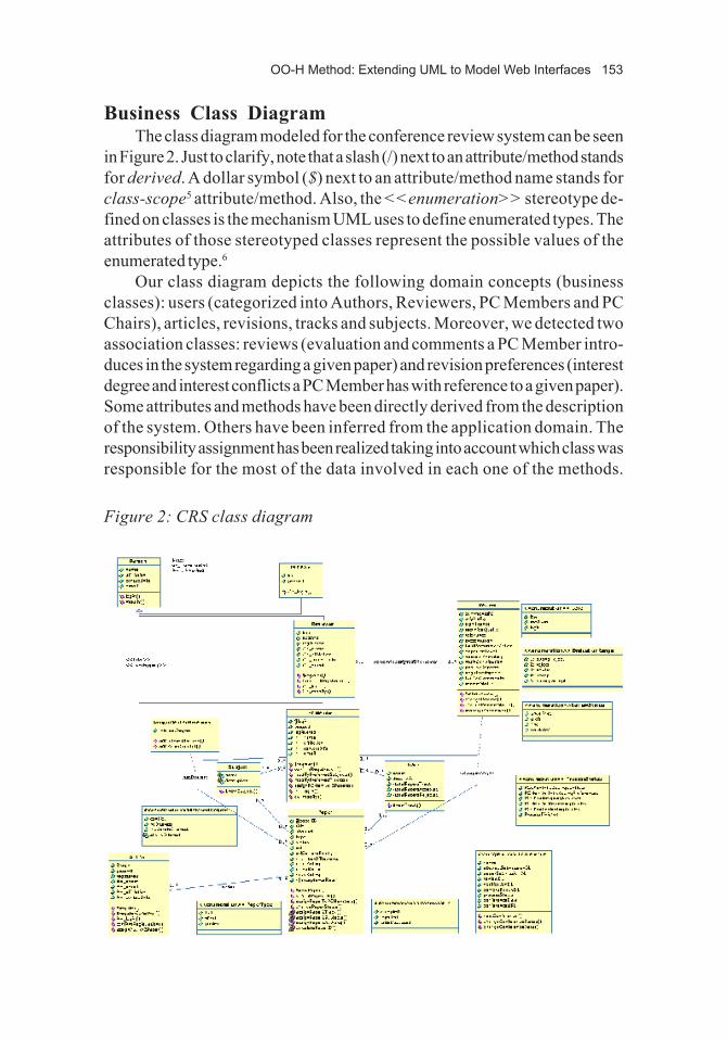
Business Class DiagramThe class diagram modeled for the conference review system can be seen
in Figure 2. Just to clarify, note that a slash (/) next to an attribute/method standsfor derived. A dollar symbol ($) next to an attribute/method name stands forclass-scope5 attribute/method. Also, the <<enumeration>> stereotype de-fined on classes is the mechanism UML uses to define enumerated types. Theattributes of those stereotyped classes represent the possible values of theenumerated type.6
Our class diagram depicts the following domain concepts (businessclasses): users (categorized into Authors, Reviewers, PC Members and PCChairs), articles, revisions, tracks and subjects. Moreover, we detected twoassociation classes: reviews (evaluation and comments a PC Member intro-duces in the system regarding a given paper) and revision preferences (interestdegree and interest conflicts a PC Member has with reference to a given paper).Some attributes and methods have been directly derived from the descriptionof the system. Others have been inferred from the application domain. Theresponsibility assignment has been realized taking into account which class wasresponsible for the most of the data involved in each one of the methods.
Figure 2: CRS class diagram

154 Gómez & Cachero
Although we tried to avoid method duplication in order to simplify the diagram,sometimes (mainly when we are dealing with methods that involve creation ordeletion of relationships between objects) it might be convenient to provide theuser with access modes from each of the classes involved.
Based on the system description, we identified six stages for the confer-ence revision process, all controlled by the PC Chair. Each stage implicitlydetermines different function sets available to each profile.• AuthorSendingPapers: In order to begin the revision process, the PC
Chair must introduce the conference parameters (PC Chair data, confer-ence dates, URLs, tracks, subjects, PC Members involved in the revisionprocess, and so on) and, as the last step, open the period for the authorsto submit papers. The system transition to this status might imply thesending of a Call for Papers to a set of selected distribution lists(DBWORLD, ISWORLD, etc).
• PCChairIntroducingConflicts: Once the paper submission period hasexpired (conference.paperSubmissionDL), the PC Chair changes thestatus of the system. This status change grants the access of the differentprofiles to a new set of tasks. For example, in this new state, the PC Chairwill be able to revise the submitted papers, change their track andsubjects, if necessary, or look for revision conflicts (e.g., PC Membersthat are authors of a submitted paper).
• PCMemberIntroducingPreferences: The following step is to open thesystem for the PC Members to introduce their preferences regarding thesubmitted papers, as well as revision conflicts not detected by the PCChair (if any).
• PCChairAssigningReviews: Once the PC Chair closes the period toregister paper preferences, and taking into account the preferences andconflicts registered in the system, it is time for the PC Chair to assignpapers to the different PC Members for revision.
• PCMemberReviewingPapers: Then, the period for each PC Member tointroduce its revisions is opened. Again, the system transition to this stateimplies the sending of an e-mail to each PC Member with informationregarding the papers the member has been assigned and the period of timeavailable to perform the revision. This phase ends when the reviewdeadline (conference.reviewDL) is reached.
• PCChairEvaluatingPapers: Once the PC Chair sets the state of thesystem to this value, and taking into account the reviews introduced by thePC Members (or the corresponding external reviewers), the PC Chairmust decide which papers are accepted and which ones are rejected.

OO-H Method: Extending UML to Model Web Interfaces 155
• ProcessFinished: This last step implies the sending of an e-mail to allpaper authors, informing them of the revision process result regarding theirpapers.
OO-H considers that the e-mails the system must send on some confer-ence state transitions are isolated inside the body of theconference.changeProcessStatus method and, therefore, out of the scope ofour models.
Modeling AssumptionsIn order to simplify the diagrams, we applied the <<singleton>> pattern
(Cachero et al., 2001) to the Conference class. This pattern implies that thegenerated system deals with a single conference (i.e., there may exist just oneobject of type conference). All papers, tracks, subjects and people in thedatabase are implicitly related to that conference. Extending such a system todeal with several conferences at a time is trivial.
Once the user requirements have been clearly identified and the businessdomain modeled, we can go one step further and focus on navigation pathsthrough the information space. The class diagram helps decide which paths aresemantically relevant, while the user-case diagram structures such pathsaccording to the user expectations of the system.
Navigation ModelingIn OO-H, the use-case diagram and the storyboard help the designer to
decompose the system interface into subsystems and pages through which theuser can navigate in a meaningful way, taking into account the user need forfulfillment of a set of functional and navigation requirements.
The construction process of the navigation access diagrams (NAD) isdivided into the following steps:(1) Grouping process on the use-case diagram: OO-H packages the use
cases attending to a set of criteria.7 For the sake of simplicity, we depictedthese grouping decisions by means of transparent package symbolsaround the use cases involved, although the actual notation (used in theOO-H case) is UML-compliant. Each package links the underlying usecases to a single navigation target, where their inner navigation paths aremodeled.
(2) Automatic derivation of the top level of the NAD diagram(3) Construction of the different NAD diagrams, driving the navigation
decisions by the corresponding storyboard

156 Gómez & Cachero
Next, we illustrate these steps by means of an example: the NAD diagramconstruct process for the PC Chair profile.
PC Chair Navigation ProfileIn this section, we will present, step by step, the construction process of
the NAD diagram corresponding to the PC Chair. The process followed toconstruct the diagrams corresponding to the other actors (PC Members,Reviewers and Authors) is analogous.
If we look again at the PC Chair use case diagram (see Figure 1), we willobserve the set of functional requirements the interface must fulfill.
In Section 2.4, we commented how this diagram was the base on whichto show decisions regarding how to group those requirements into navigationtargets (NT), attending at semantic, functional dependency and data criteria.We say we are using semantic criteria when we group use cases that have asimilar aim. As an example, in Figure 3, we can observe how the use-casesview Reviews and view Statistics have been grouped under the NT ViewProcess Data, due to the fact that both provide reports on the reviewinformation (one aggregated, the other one detailed) contained in the system.
Figure 3: UC grouping process

OO-H Method: Extending UML to Model Web Interfaces 157
On the other hand, in order to gather view Reviewers Evaluation and Accept/Reject Papers, we applied what we call a functional dependency criterion, thatis, we departed from the premise that in order to be able to accept and rejectpapers, we must have a synthesized view of every reviewer evaluation in orderto help the PC Chair to make a sound decision. Last, the use casesChangeConferenceStatus and ManageConferenceInfo have been groupedunder the NT Manage Conference, following a data criterion, that is, due tothe fact that both access and manipulate data of the Conference class.
The grouping process entails an interface structure. Consequently, themore careful this process is performed, the higher the quality of the finalinterface structure will be.
Once this process is finished, the next step is to dive into each grouping anddefine the inner navigation paths. In order to illustrate the navigation designdecisions, we are showing the storyboard corresponding to the first NT,Manage Conference.
PC Chair Profile Entry PointIn Figure 4, we observe the modeling of the entry point to the application
(represented by the requirement link Entry Point). One possible set of
Figure 4: PCChair NAD Level 0

158 Gómez & Cachero
storyboard pages corresponding to this diagram is showed in Figures 5 and 6.The first abstract page corresponds to a form for the user to log in to the system.This process involves a user login, password and profile, which correspond to
Figure 5: Login
Figure 6: Menu PCChair

OO-H Method: Extending UML to Model Web Interfaces 159
the parameters (all mandatory) of the method PCChair.login. If the user exists(condition that is reflected in the Fo Valid User), the user will be shown a menu,where a link to each of the five NT identified (see Figure 7) is presented. Sucha menu is represented by the collection construct Menu PCChair.
Each NT can be further “exploded” to show detailed internal navigation.To illustrate this, next we will show the internal structure of the NT ManageConference.
Navigation Target “Manage Conference”When the PC Chair selects the Manage Conference option,8 the interface
subsystem modeled inside the corresponding NT is accessed. The entry pointto this NT (requirement link Conference Maintenance, see Figure 7) pointsat a new collection, called Conference Menu, that differs from the previous onein the type of links departing from it; while in the PCChair Menu collection, thelinks had the visualization attribute set to show in destination, this time they areof type show in origin (hollow arrowheads of Introduce Conference andView Conference links). This represents the fact that, in this case, no link toa new page must be generated, but that the information corresponding to thedestination classes must be directly presented to the user, provided that thecorresponding Fo is evaluated to be true.
Furthermore, as both filters (conference.population)==0 / conference.population > 0) are disjoint, only one view will be available at a time: if theconference has not yet been created (it is the first time the PC Chair enters thesystem), the screen corresponding to the createConference method willappear (see Figure 8). This page gathers the set of parameters the method NewConference requires. Once the method has been invoked and the controlreturned to the interface, the response link Conference Created drives the useragain to the Conference Menu. This time, however, when the filters arechecked again, it is the View Conference link that is evaluated to be true, andso the system will automatically generate the page shown in Figure 9. This pageprovides a view of the conference data, together with three buttons (Tracks,Subjects and Change Conference Data), corresponding to the three links setto show in destination that depart from the Conference navigation class.Activating each one of these links, we will navigate to the views ChangeConference Data (see Figure 10), Tracks (see Figure 11) and Subjects (seeFigure 12), respectively. Also, there is another button (Change ConferenceStatus) that actually executes the homonym service, with the value of its inputparameter (newStatus) set to the string selected in the selection list shown inFigure 9.

160 Gómez & Cachero
This selection list is the result of associating a selection introduction modeto the change service status parameter.9 At this point, the reader may wonderhow OO-H generates the mediator for the interconnection with preexistentlogic modules. In fact, the answer is in the class diagram. We already noted howthe class diagram can show the interface to underlying business libraries. Inorder to identify those libraries, OO-H defines the <<legacy>> stereotype that,associated to domain classes, reflects the fact that those classes are part of apreexistent library. Also, services in those <<legacy>> classes have their input/output parameters defined at domain level. At navigation level (in the NADdiagram), we thus just have to center on the way the user is going to introducethose parameters, and whether introduction is mandatory or not: only manda-tory attributes that have no default value in the class diagram or in the navigationdiagram appear as mandatory in the interface. Before the generation processis executed, the CASE tool detects <<legacy>> classes and requires thedesigner to enter the necessary solution-space data (physical location of thelibrary, desired protocol to actually connect to the library interface, etc.) togenerate the mediator. Note how this fact obliges the <<legacy>> classes tocapture the exact interface to the desired library. All this information is kept inan XML template structure (Tlogic: see section “View Refinement”), which islater used by the tool to perform the generation process.
Figure 7: Manage conference

OO-H Method: Extending UML to Model Web Interfaces 161
In Figure 10, we can also observe how the different method parametersmay have a default value associated (in this case, the actual value of thecorresponding class attributes). Also note that, when not otherwise stated, adefault response link is supposed to go back to the view from which the servicewas invoked.
Figure 8: New conference
Figure 9: Conference view/change status

162 Gómez & Cachero
As the reader will have already inferred, it is the visualization attribute(explained in Section 2.2) that characterizes the final abstract page structure ofthe interface. We call this page structure abstract, because there is nothing thatprevents those pages from being further composed into a frame structure or anyother mechanism that allows the coexistence of different views of the system onthe same physical screen.
Figure 11: New track
Figure 10: Change conference data

OO-H Method: Extending UML to Model Web Interfaces 163
In Figure 13, we can observe the interconnection of the screenshotscaptured in Figures 5 to 12. In the next section, we will explain how this siteview interconnection perfectly matches with the APD diagram, automatically
Figure 12: New subject
Figure 13: Site view

164 Gómez & Cachero
generated by the OO-H CASE tool departing from the corresponding NADdiagram. Also, note how the storyboard presents a link from every abstractpage to the NT origin, another one to the application entry point and anotherone pointing at the previous abstract page in the navigation path. OO-Hautomatically generates those links (from each page to the home page, to theNT root page and to the previous page in the navigation path) if not otherwisestated.
Although at this stage of the process we already have all the informationneeded to automatically generate a functional prototype, OO-H recognizes theneed for a greater level of interface sophistication than that provided by theinformation gathered at NAD level, regarding appearance and usability fea-tures. The abstract presentation diagram (APD) and the composite layoutdiagram (CLD) provide a set of mechanisms to refine the interface at a lowerlevel of abstraction.
View Refinement: Presentation ModelingA default APD, reflecting the abstract page structure of the interface, can
be automatically derived from the NAD diagram. This default APD gives afunctional but rather simple interface (with default location and styles for eachinformation or interaction item, and only simple patterns applied), which willprobably need further refinements in order to become useful for its inclusion inthe final application. It can, however, serve as a prototype on which to validatethat the user requirements have been correctly captured. Furthermore, itseparates the different features that contribute to the final interface appearanceand behavior by using a page taxonomy, based on the concept of templates andexpressed as XML documents, which are, namely:(1) Tstruct — Used to capture the information that needs to be shown(2) Tform — Used when the page, apart from information, includes calls to
underlying logic(3) Tlink — Captures the interconnection and dependencies among pages(4) Tfunction — Gathers client functionality used in the different pages(5) Texternal — Used to gather type, location and behavior of external
elements (such as images, applets, etc.) that may refine the initial interface(6) Tlayout — Where the location of elements and the definition of simulta-
neous views and synchronization is captured(7) Tstyle — Where OO-H maintains features such as typography or colour
palette for each element of the interface(8) Twidget — Where implementation constructs are related to the different
information and interaction items depending on the final implementationplatform and language
OO-H Method: Extending UML to Model Web Interfaces 165
(9) Tlogic — Where the system keeps implementation details regardinginteraction with underlying business logic (kind of service, parameters,connection protocol, etc.)
The refinement process consists thus on the modification of the defaultAPD structure. This process is greatly simplified with the application of a seriesof APD-related patterns captured in the OO-H catalog (Conallen, 1999).Furthermore, the catalog provides an executable python routine (transforma-tion rule in OO-H terminology) for each materialization of the patterns. Thisroutine, when loaded in the OO-H CASE tool and executed, changes thecontents of the required APD abstract pages. Also, these routines may causeany new page, link or dependency to appear, disappear, or be modified on thediagram. OO-H provides yet another way to manipulate some of the abstractpages (namely, Texternal, Tlayout, Tstyle, Twidget), by means of the compos-ite layout diagram (CLD). In this view, the location and visual style of elementscan be edited, widgets (implementation constructs) can be specified and newelements can be added to improve the visual impact of the generated interface.
The last step of the process, once the abstract pages (XML documents)have been refined, is to feed the system description (those XML documents)to a model compiler (not discussed here) that has the target-environmentknowledge that permits the generation of an operational Web interface. It isimportant to note that the code-generator receives as its only input that XML-based system description, which therefore contains all the information kept inthe different diagrams. Changes in such diagrams cause the XML specificationto be regenerated, which assures that no inconsistencies arise between bothrepresentations of the system.
In the next section, we will show part of the default APD generated fromthe PC Chair NAD diagram.
PC Chair Default Interface Site ViewThe OO-H CASE tool includes an algorithm to generate, departing from
the NAD diagram, the set of pages that makes up the site view of the interface(the detailed algorithm can be found in Gómez, Cachero, & Pastor, 2001) .Note how only Tstruct, Tform and Tlink pages are relevant to the site view ofthe system, and so how the APD diagram graphically shows them. OO-Hincludes a default Tfunction (client-side logic to control user inputs for methodparameters), a default Tlocation and a default Tstyle. Furthermore, a defaultTwidget is applied to the different interface elements depending on the targetimplementation language.10. Also note how the contents of the Tlink global pageis shown by means of links connecting the Tstruct and Tform pages. The

166 Gómez & Cachero
construction of Tlogic, based on the definition of interfaces, is out of the scopeof this chapter.
If we look back to Figure 13 (storyboard snapshot interconnectiondiagram) and compare it with Figure 14 (APD partial view), we can see howthey match: the only difference is that snapshots S2 and S3 (Figures 5 and 6)are now gathered in a single APD page (Conference_Menu) due to the factthat, in Figure 7 (NAD diagram), we defined that both views were shown inorigin, and so embedded in the same abstract page, represented by thecollection Conference Menu. The remaining snapshots can be directly asso-ciated with exactly one abstract page at the APD level.
DISCUSSION11
The goal when developing OO-H has never been to provide “yet anothermethod” but to take advantage of proven successful ideas of existing method-ologies and practices in related fields, from which we borrowed concepts suchas use cases, patterns, collections or links, just to name a few. The followingstep has been to integrate them into a sound proposal, while contributing some
Figure 14: APD PCChair Profile

OO-H Method: Extending UML to Model Web Interfaces 167
new ideas to improve identified gaps. Therefore, OO-H shares many conceptswith other methods for hypermedia and Web design, many regarding thenavigation model. In fact, these similarities also exist among the most relevantmethods and methodologies being actually supported, among which we couldcite UWE, WSDM, ADM-2, WebML, OO-H, OOHDM or HDM2000.Some of these similarities are as follows:• All proposals identify the necessity of a brand new model: the navigation
model, to tackle the Web application development process. Inside thisdiagram, all proposals distinguish between information and access struc-tures.
• All proposals clearly separate content, navigation and presentation spaceby means of different models.
• There is a general agreement in the necessity of any kind of navigationdiagram, for which standard methodologies do not provide the necessaryconstructs. So, such standard methodologies have been extended or abroad new notation and model have been proposed.
• All proposals aim at defining a precise and systematic, even in some stepsautomated, process for the development of the Web application.
• All proposals present an exhaustive authoring process (a method and anotation).
• All proposals avow the necessity of any kind of constraint language toaugment the precision of the Web application models.
• All proposals avow the necessity of a CASE tool that supports the wholeprocess.
Far from being a drawback, we think this sharing of concepts is one of thereasons for the rapid development of Web engineering. The IIWOST’01experience demonstrates, from our point of view, that hypermedia designmethods are reaching a state of maturity in which a set of premises is beingsettled. This makes it relatively straightforward to understand the conceptsbehind other proposals and to reflect together on missing semantics andaccurate definitions of concepts and constructs.
However, there are many differences among the different proposals. Someapproaches (e.g., UWE) aim at covering the whole life-cycle of the Webapplication, while others (e.g., OO-H) center on the authoring process. Also,the data-orientation of some approaches (e.g., ADM-2, WebML) contrastswith the user-orientation of many others (e.g., OOHDM, OO-H). Only someapproaches formalise the sketching and storyboarding techniques (e.g.,OOHDM) widely used by user interface designers.

168 Gómez & Cachero
The design activity also greatly differs in the level of detail. While someapproaches prefer to use external tools for refining interfaces, or even connectthem with their models (e.g., WebML), others prefer the integration of layouton the same tool, thus providing an integrated development environment, evenat the cost of less elaborated visual interfaces (e.g., OO-H).
Another important aspect regards the extent to which different proposalsabstract Web application functionality. Most methods studied so far providetraditional database functionality (insert, update, delete). However, the kind ofservices required by actual Web applications is far more complex, and thedegree to which those services are integrated in the proposals greatly differs.Although database models could be extended (and in fact are being extended,see e.g., WebML) to deal with such services, we claim OO models, in whichservices are first-class concepts, provide a more flexible platform with whichto model Web functionality. Specifically, the class diagram proposed in suchmethods is prepared to include the interfaces needed to connect with underlyingbusiness logic modules, thus facilitating the functionality integration process.However, and although traditional software engineering methodologies pro-vide the designer with the notation and models already proven successful for thedevelopment of business services and transactions (which is the reason whyOO-H does not provide any new diagram or construct for this part of the Webapplication), they were not designed to deal with concepts such as Internettransactions (set of services that may be executed on different independentdatabases, with no knowledge of each other), client functionality, Webservices, etc. OO-H is currently working on the abstraction of those concepts,which are part of the research trends in the field.
Also, personalization features, which should be present at every stage ofdevelopment, are diversely covered in the different approaches. In this sense,OO-H provides a basic level of personalization, based on departing from userprofiles and designing a different model for each user type. More evolvedproposals (e.g., WebML) provide frameworks for one-to-one personalizationand even support for interface proactive behavior. Although this topic wouldneed a whole chapter on its own, we would like to note that OO-H regardspersonalization as a core activity for Web engineering. This task, together withnavigation design, makes, from our point of view, one of the greatest differ-ences between traditional software development processes (including that ofdistributed applications) and the Web development process.
Moreover, the degree to which those proposals are supported by a CASEtool greatly differs: while some approaches have a fully operational CASE, withgeneration code capabilities, others have support just for the notation andevolution of the different models, while still others have their associated tool

OO-H Method: Extending UML to Model Web Interfaces 169
acting as a mere diagram editor. In this sense, OO-H already has a CASEcapable of generating fully operative interfaces, and we are currently workingon the generation of modules that implement the connection with business logic.Furthermore, this tool has powerful extension capabilities due to the belief thatWeb concepts are likely to greatly evolve in the next years. Recent studies showthe low impact of Web methodologies in current enterprise practices. We thinkthe existence of fully operative, easy-to-use CASE tools supporting suchmethodologies is a must if the research community wants to change this trend.
Finally, and despite the great number of shared concepts, there are greatcontroversies regarding navigation, especially the level of abstraction at whichit should be defined. From OO-H, we claim that although a design navigationmodel (gathering the abstract site view of the interface) is needed, and evenmore if we aim at providing any kind of automatic code generation support,there is, however, also a need for a device independent navigation model, whichis, as far as we know, not provided by any methodology. Until now, all models(including ours) have had in mind the concept of abstract page when dealingwith navigation constructs, probably due to our background as Web develop-ers. However, from OO-H, we think it would be advisable to preserve a certain“flavor” among implementations of the same application for different devices.That is the reason why we are currently working on a navigation view with whichthe concept of node is based on the user requirements, rather than on the classdiagram representing the domain information structure, which is the basisadopted so far in other proposals.
CONCLUSIONS AND OO-H RESEARCHDIRECTIONS
It is commonly avowed that current interface-related languages are tootarget-environment dependent and, therefore, lack the flexibility needed for thedevelopment of complex Web applications. Well-defined software develop-ment processes are necessary in order for the community of software engineersto design Web-based applications in a systematic way and thus avoid the risksof failure involved in ad hoc development processes. Our purpose has been toaddress these problems in the Web engineering context by means of aconceptual modeling approach that has been proven successful for softwareproduction from conceptual models.
In order to properly capture the particulars associated with the design ofWeb interfaces, OO-H method adds several navigation and interface con-structs that define the semantics suitable for capturing the specific functionality

170 Gómez & Cachero
of Web application interfaces. Two new kinds of diagrams, the navigationaccess diagram and the abstract presentation diagram, have been introduced.Both the NAD and the APD capture relevant information for the interfacedesign by means of a set of patterns, which are defined in an interface patterncatalog. The NAD, which is based on an OO class diagram, is centered oninformation and navigation user requirements and provides each user-type witha different view of the system. Each piece of information introduced in the NADis mapped into a different construct in a default APD. The APD is based on theconcept of templates, and its underlying structure is expressed in standardnotation. We can perform further refinements on the APD in order to improvethe interface visual quality and usability.
From there, a functional interface can be generated in an automated way.In contrast to other existing Web methods, the approach presented in this paperdoes not intend to be yet another method for Web modeling but rather anextension of any consolidated OO conceptual modeling approach. Summariz-ing, the most relevant contributions of this chapter are the following:• The detailed presentation of OO-H method as an interface modeling
approach that extends conventional methods starting from navigation userrequirements.
• The idea of integration, departing from the conceptual description of theproblem, of complex application behavior by means of explicit serviceinteraction modeling. In this sense, OO-H provides the mechanisms todefine how each parameter is going to be fed to each service and how theuser is going to visualize the service results.
• The use of a pattern catalog to evolve the schemas in order to speed upthe development process, improve interface quality and guarantee designexperience reuse.
• The notion of transformation rule, associated with each of the possiblepattern implementations, as a way to simplify and systematize the modi-fication process of the APD schema.
• The use of a taxonomy of construct templates, which is defined in astandard notation, to build the different constituents (information, layout,input data, client functionality) of the APD as necessary.
• The notion of default APD, which is built by applying a set of mapping rulesfrom the different elements of the NAD.
OO-H is not a closed proposal: the modeling of existing and to-comeapplications will cause its semantic constructs to evolve and be extended tocapture new interface requirements. As an example, we are already working on

OO-H Method: Extending UML to Model Web Interfaces 171
the interface-related event modeling. Although Web applications require anevent mechanism similar to other traditional applications (e.g., to performpunctual or periodic tasks without need for user interaction, to respond to thefinish event of asynchronous services, etc.), we think they also require aninterface-related event mechanism that manages which views are available foreach user at each moment. In this sense, one possibility is the use of high-levelstate charts, where each state represents a set of views available for a given userat a given time. A transition condition in this case would imply a change in theset of views the user can access. This last point can be viewed as part of abroader problem, which is that of the integration of workflow activities as partof the authoring process. Also, we think a powerful but yet simple mechanismto specify synchronization of views is necessary in this environment. In thissense, OO-H could benefit from work developed in the multimedia community,where synchronization is a first-order aspect.
Ongoing work in OO-H further includes (1) how to achieve a greater levelof personalization (including the definition of a personalization framework), (2)how to detect a greater range of patterns and definition of their correspondingOO-H transformation rules and (3) how to provide support for a broader rangeof implementation architectures, platforms and languages.
REFERENCESBell, R. (1998). Code Generation from Object Models. Embedded Systems
Programming. 3, 1–9.Cachero, C. Gómez, J., et al. (2001). Conference Review System: A Case of
Study. (2001). In D. Schwabe, (Ed.), Proceedings of the First Interna-tional Workshop on Web-Oriented Software Technology (195–227).Valencia University of Technology.
Ceri, S., Fraternali, P., et al. (2000). Web Modeling Language (WebML): AModeling Language for Designing Web Sites. In I. Herman, (Ed.),Proceedings of 9th International WWW Conference. IEEE Press.
Conallen, J. (1999). Modeling Web Application Architectures with UML.Communications of the ACM, 42(10), 63–70.
Directory Services Markup Language (DSML). (2001). http://www.dsml.org/.
Gartner Group, Inc. (2001). The Future of Web Services: Dynamic BusinessWebs. Market Analysis.
Gellersen, H.W. & Gaedke, M. (1999). Object-Oriented Web ApplicationDevelopment. IEEE Internet Computing, 3(1), 60–68.

172 Gómez & Cachero
Gómez, J., Cachero, C., & Pastor, O. (2001). Conceptual Modeling ofDevice-Independent Web Applications. IEEE Multimedia, 8(2), 26–39.
Manola, F. (1999). Technologies for a Web Object Model. IEEE InternetComputing, 3(1), 38–47.
Martin, D., Birbeck, M., et al. (2000). Professional XML. WROX.Mecca, G., Merialdo, P., & Atzeni, P. (1999). Araneus in the Era of XML.
IEEE Data Engineering Bulletin, 42(10), 63–70.Murugesan, S., Deshpande, Y., et al. (1999). Web Engineering: A New
Discipline for Development of Web-Based Systems. In S. Murugesan(Ed.), Proceedings of First ICSE Workshop on Web Engineering.
Pressman, R.S. (2000). Software Engineering: A Practitioner’s Approach.Fifth ed. New York: McGraw-Hill.
Schwabe, D. & Almeida, R. (1999). A Method-Based Web ApplicationDevelopment Environment. In D. Schwabe, (Ed.) Proceedings of 8thInternational WWW Conference. IEEE Press.
Simple Object Access Protocol (SOAP). (2001). http://www.develop.com/soap/.
Semantic Web. (2001). http://www.w3.org/2001/sw.Universal Description, Discovery and Integration (UDDI). (2001). http://
uddi.microsoft.com/.User Interface Modeling Language (UIML). (2001). http://www.uiml.org.UML Specification. V1.3. (1999). http://www.rational.com/uml/index.jsp.Warmer, J. & Kleppe, A. (1998). The Object Constraint Language. Precise
Modeling with UML. Reading, MA: Addison-Wesley.Web Services Description Language (WSDL). (2001).http: //msdn.microsoft.
com/xml/general/wsdl.asp.
ENDNOTES1 The special characteristics and requirements of Web applications and the
Web development process are beyond the scope of this chapter. Inter-ested readers are referred to Pressman (2000), where a good introduc-tion is provided.
2 Automatic links tend to be visualized in origin, while manual links tend tobe visualized in destination. However, there are cases in which it can beuseful to combine both characteristics in a different way.
3 More detailed information on the semantics of the different constructs andon the OO-H process to specify navigation features can be found in(Gómez, Cachero, & Pastor, 2001).

OO-H Method: Extending UML to Model Web Interfaces 173
4 The selected case of study has been proposed by Daniel Schwabe in thecontext of the first International Workshop on Web Oriented SoftwareTechnology (IWOOST’2001).
5 In UML 1.3, the class-scope $ notation has been deprecated andsubstituted by an underlined attribute/method name. OO-H will changethe notation support accordingly in future versions of the tool.
6 This way of defining enumerated types has been included in UML 1.47 These grouping criteria will be further explained in Section 2.8, when we
show the PC Chair navigation profile.8 In the OO-H diagrams, an asterisk next to the link name means that the
set of activation links is not complete (that is, is not made up by every linkfrom which the user might have arrived to the actual view). Also, an arrowwith a filled head means that its visualization metamodel attribute is set toshow in destination, while, if it has a hollow head, the correspondingvalue is show in origin.
9 See Section 1 for a description of the different introduction modes formethod parameters. More information on services and input parameterscan be found at http://www.dlsi.ua.es/~ccachero/reports/services.pdf.
10 The XML specification of every page is available through the tool byclicking on the corresponding page or by means of a menu.
11 An interesting experience regarding modeling methods was held in Valenciain June 2001 during the IIWOST’01. In this workshop, people from someof the most relevant research groups proposed their solution to a commonproblem (the Conference Review System presented in this chapter). Thisexperience provided a suitable forum, where it was possible to discuss thedifferent approaches from a practical point of view. The different solutionsto the case are in the roots of this brief comparison. Readers interested ina deeper discussion or in a description of the different proposals arereferred to the congress proceedings.