ontrol and circuit breakers tesys p c rotection … circuit breakers tesys gv references motor...
TRANSCRIPT

B6/1
Cir
cuit
b
reak
ers
Circuit breakersTeSys GV, GB
Circuit breakers - TeSys GV, GBType of product Range Pages
Magnetic circuit breakers for motorsTeSys GV Up to 15, 30 kW B6/2
Thermal magnetic circuit breakers for motorsTeSys GV
Up to 15, 37 or 110 kW B6/4
Add-on blocks, accessories, for motor circuit breakers
B6/10
Thermal magnetic circuit breakers for control circuits, Solenoid valves or transformersTeSys GB, GV
From 0.5 to 23 A B6/26
TeSy
s Control and Protection Components
1.1
Chapter
B6
Technical Data for Designers B6/29
[email protected] GmbH

B6/2
TeSys GV
References
Magnetic motor circuit breakers from 0.06 to 15 kWGV2 LE: control by rocker lever, connection by screw clamp terminalsStandard power ratings of 3-phase motors 50/60 Hz in category AC-3
Magnetic protection rating
Tripping current Id ± 20 %
Use in association with thermal overload relay
Reference
400/415 V 500 V 690 VP Icu Ics (1) P Icu Ics (1) P Icu Ics (1)
kW kA kW kA kW kA A A0.06 g g – – – – – – 0.4 5 LR2 K0302 GV2LE03
0.09 g g – – – – – – 0.4 5 LR2 K0304 GV2LE03
0.12 g g – – – 0.37 g g 0.63 8 LR2 K0304 GV2LE04
0.18 g g – – – – – – 0.63 8 LR2 K0305 GV2LE04
– – – – – – 0.55 g g 1 13 LR2 K0305 GV2LE05
0.25 g g – – – – – – 1 13 LR2 K0306 GV2LE05
– – – – – – 0.75 g g 1 13 LR2 K0306 GV2LE05
0.37 g g 0.37 g g – – – 1 13 LR2 K0306 GV2LE05
0.55 g g 0.55 g g 1.1 g g 1.6 22.5 LR2 K0307 GV2LE06
– – – 0.75 g g – – – 1.6 22.5 LR2 K0307 GV2LE06
0.75 g g 1.1 g g 1.5 3 75 2.5 33.5 LR2 K0308 GV2LE07
1.1 g g – – – – – – 2.5 33.5 LR2 K0308 GV2LE07
1.5 g g 1.5 g g 3 3 75 4 51 LR2 K0310 GV2LE08
– – – 2.2 g g – – – 4 51 LR2 K0312 GV2LE08
2.2 g g 3 50 100 4 3 75 6.3 78 LR2 K0312 GV2LE10
3 g g 4 10 100 5.5 3 75 10 138 LR2 K0314 GV2LE14
4 g g 5.5 10 100 – – – 10 138 LR2 K0316 GV2LE14
– – – – – – 7.5 3 75 10 138 LRD 14 GV2LE14
– – – – – – 9 3 75 14 170 LRD 16 GV2LE16
5.5 15 50 7.5 6 75 11 3 75 14 170 LR2 K0321 GV2LE16
7.5 15 50 9 6 75 15 3 75 18 223 LRD 21 GV2LE20
9 15 40 11 4 75 18.5 3 75 25 327 LRD 22 GV2LE22
11 15 40 15 4 75 – – – 25 327 LRD 22 GV2LE22
15 10 50 18.5 4 75 22 3 75 32 416 LRD 32 GV2LE32
(1) As % of Icu.g) > 100 kA.
TeSys protection componentsMagnetic motor circuit breakers GV2 LE
GV2 LE10
DF5
2614
4.tif
Characteristics:pages B6/30 and B6/31
Dimensions:pages B6/43 to B6/45
Schemes:page B6/48
[email protected] GmbH

B6/3
Cir
cuit
b
reak
ers
TeSys GV
References
Motor circuit breakers from 0.09 to 30 kWGV2 L: Control by rotary knob, connection by screw clamp terminalsStandard power ratings of 3-phase motors 50/60 Hz in category AC-3
Magnetic protection rating
Tripping current Id ± 20 %
Use in association with thermal overload relay (class 10 A)
Reference
400/415 V 500 V 690 VP Icu Ics (1) P Icu Ics (1) P Icu Ics (1)
kW kA kW kA kW kA A A0.09 g g – – – – – – 0.4 5 LRD 03 GV2L030.12 g g – – – 0.37 g g 0.63 8 LRD 04 GV2L040.18 g g – – – – – – 0.63 8 LRD 04 GV2L04– – – – – – 0.55 g g 1 13 LRD 05 GV2L050.25 g g – – – – – – 1 13 LRD 05 GV2L05– – – – – – 0.75 g g 1 13 LRD 06 GV2L050.37 g g 0.37 g g – – – 1 13 LRD 05 GV2L050.55 g g 0.55 g g 1.1 g g 1.6 22.5 LRD 06 GV2L06– – – 0.75 g g – – – 1.6 22.5 LRD 06 GV2L060.75 g g 1.1 g g 1.5 4 100 2.5 33.5 LRD 07 GV2L071.1 – – – – – – – – LRD 08 GV2L081.5 g g 1.5 g g 3 4 100 4 51 LRD 08 GV2L08– – – – – – – – – LRD 08 GV2L082.2 g g 3 g g 4 4 100 6.3 78 LRD 10 GV2L103 g g 4 10 100 5.5 4 100 10 138 LRD 12 GV2L144 – – – – – – – – LRD 14 GV2L14– – – – – – 7.5 4 100 10 138 LRD 14 GV2L14– – – – – – 9 4 100 14 170 LRD 16 GV2L165.5 50 50 7.5 10 75 11 4 100 14 170 LRD 16 GV2L167.5 50 50 9 10 75 15 4 100 18 223 LRD 21 GV2L209 50 50 11 10 75 18.5 4 100 25 327 LRD 22 GV2L2211 50 50 15 10 75 – – – 25 327 LRD 22 GV2L2215 50 50 18.5 10 75 22 4 100 32 416 LRD 32 GV2L32
GV3 L: control by rotary knob, connection by EverLink® BTR screw connectorsStandard power ratings of 3-phase motors 50/60 Hz in category AC-3
Magnetic protection rating
Tripping current Id ± 20 %
Use in association with thermal overload relay (class 10 A)
Reference
400/415 V 500 V 690 VP Icu Ics (1) P Icu Ics (1) P Icu Ics (1)
kW kA kW kA kW kA A A11 100 100 15 12 50 18.5 6 50 25 350 LRD 325 GV3L25
15 100 100 18.5 12 50 22 6 50 32 448 LRD 332 GV3L32
18.5 50 100 22 12 50 37 6 50 40 560 LRD 340 GV3L40
22 50 100 30 12 50 45 6 50 50 700 LRD 350 GV3L50
30 50 100 37 12 50 55 6 50 65 910 LRD 365 GV3L65
Connection by EverLink® BTR screw connectors, for assembly with a contactor
To assemble a GV3 L25 to L65 circuit breaker with an LC1 D40A to D65A contactor, it is possible to use the circuit breaker supplied without downstream EverLink® power terminal block. To order this product, add the digit 1 to the end of the references selected above. Example: GV3 L65 becomes GV3 L651.Connection by lugs
To order these circuit breakers with connection by lugs, add the digit 6 to the end of reference selected above. Example: GV3 L32 becomes GV3 L326. (1) As % of Icu. Associated current limiter or fuses, where required. See characteristics page B6/33.g > 100 kA.
TeSys protection componentsMagnetic motor circuit breakers GV2 L, GV3 L and GK3 EF80
GV2 L10
DF5
2614
5.tif
GV3 L65
DF5
2614
6.tif
Characteristics:pages B6/30 to B6/33
Dimensions:pages B6/43 to B6/47
Schemes:page B6/48
[email protected] GmbH

B6/4
TeSys GV
TeSys protection componentsThermal-magnetic motor circuit breakers GV2 ME
References
Motor circuit breakers from 0.06 to 15 kW / 400 V, with screw clamp terminalsGV2 ME with pushbutton controlStandard power ratings of 3-phase motors 50/60 Hz in category AC-3
Setting range of thermal trips (2)
Magnetic tripping current Id ± 20 %
Reference
400/415 V 500 V 690 VP Icu Ics (1) P Icu Ics (1) P Icu Ics (1)
kW kA % kW kA % kW kA % A A– – – – – –
– – – 0.1…0.16 1.5 GV2ME01
0.06 g g – – –
– – – 0.16…0.25 2.4 GV2ME02
0.09 g g – – –
– – – 0.25…0.40 5 GV2ME03
0.12 0.18
gg
g g
– –
– –
– –
0.37 –
g –
g –
0.40…0.63 8 GV2ME04
0.25 g g – – –
0.55 g g 0.63…1 13 GV2ME05
0.37 0.55 –
g g –
g g –
0.37 0.55 0.75
g g g
g g g
– 0.75 1.1
– g g
– g g
1…16 22.5 GV2ME06
0.75 g g 1.1 g g
1.5 3 75 1.6…2.5 33.5 GV2ME07
1.1 1.5
g g
g g
1.5 2.2
g g
g g
2.2 3
3 3
75 75
2.5…4 51 GV2ME08
2.2 g g 3 50 100
4 3 75 4…6.3 78 GV2ME10
3 4
g g
g g
4 5.5
10 10
100 100
5.5 7.5
3 3
75 75
6…10 138 GV2ME14
5.5 –
15 –
50 –
7.5 –
6 –
75 –
9 11
3 3
75 75
9…14 170 GV2ME16
7.5 15 50 9 6 75
15 3 75 13…18 223 GV2ME20
9 15 40 11 4 75
18.5 3 75 17…23 327 GV2ME21
11 15 40 15 4 75
– – – 20…25 327 GV2ME22 (3)
15 10 50 18.5 4 75 22 3 75 24…32 416 GV2ME32
Motor circuit breakers from 0.06 to 15 kW / 400 V, with lugsTo order thermal magnetic circuit breakers with connection by lugs, add the digit 6 to the end of reference selected above. Example: GV2 ME08 becomes GV2 ME086.Thermal magnetic circuit breakers GV2 ME with built-in auxiliary contact block
With instantaneous auxiliary contact block (composition, see page B6/11):
b GV AE1, add suffix AE1TQ to the motor circuit breaker reference selected above. Example: GV2 ME01AE1TQ.b GV AE11, add suffix AE11TQ to the motor circuit breaker reference selected above. Example: GV2 ME01AE11TQ.b GV AN11, add suffix AN11TQ to the motor circuit breaker reference selected above. Example: GV2 ME01AN11TQ.
These circuit breakers with built-in contact block are sold in lots of 20 units in a single pack.
(1) As % of Icu.(2) The thermal trip setting must be within the range marked on the graduated knob.(3) Maximum rating which can be mounted in enclosures GV2 MC or MP, please consult your Regional Sales Office. g > 100 kA.
GV2 ME10
DF5
2613
4.tif
Characteristics:pages B6/51 to B6/54
Dimensions:pages B6/70 to B6/72
Schemes:page B6/82
[email protected] GmbH

B6/5
Cir
cuit
b
reak
ers
TeSys GV
TeSys protection components Thermal-magnetic motor circuit breakers GV2 ME
References
Motor circuit breakers from 0.06 to 11 kW, with spring terminal connectionsGV2 ME (1) with pushbutton controlStandard power ratings of 3-phase motors 50/60 Hz in category AC-3
Setting range of thermal trips (3)
Magnetic tripping current Id ± 20 %
Reference
400/415 V 500 VP Icu Ics (2) P Icu Ics (2)
kW kA % kW kA % A A– – – – – – 0.1…0.16 1.5 GV2ME013
0.06 g g – – – 0.16…0.25 2.4 GV2ME023
0.09 g g – – – 0.25…0.40 5 GV2ME033
0.120.18
gg
gg
– – – 0.40…0.63 8 GV2ME043
0.250.37
gg
gg
0.37 g g 0.63…1 13 GV2ME053
0.370.55
gg
gg
0.370.550.75
ggg
ggg
1…1.6 22.5 GV2ME063
0.75 g g 1.1 g g 1.6…2.5 33.5 GV2ME073
1.11.5
gg
gg
1.52.2
gg
gg
2.5…4 51 GV2ME083
2.2 g g 3 50 100 4…6.3 78 GV2ME103
34
gg
gg
45.5
1010
100100
6…10 138 GV2ME143
5.5 15 50 7.5 6 75 9…14 170 GV2ME163
7.5 15 50 9 6 75 13…18 223 GV2ME203
911
1515
4040
11 4 75 17…23 327 GV2ME213
11 15 40 15 4 75 20…25 327 GV2ME223
Contact blocksDescription Mounting Maximum
numberType of contacts
Sold in lots of
Unit reference
Instantaneous auxiliary contacts
Front 1 N/O + N/C 10 GVAE113N/O + N/O 10 GVAE203
LH side 2 N/O + N/C 1 GVAN113N/O + N/O 1 GVAN203
AccessoryDescription Application Sold in
lots ofUnit reference
Cable end reducer For connection of conductors from 1 to 1.5 mm2 20 LA9D99
(1) For connection of conductors from 1 to 1.5 mm2, the use of an LA9 D99 cable end reducer is recommended.(2) Maximum rating which can be mounted in enclosures GV2 MC or MP, please consult your Regional Sales Office(3) The thermal trip setting must be within the range marked on the graduated knob.g > 100 kA.
GV2 MEpp3
DF5
2613
5.tif
LA9 D99
DF5
3389
8.ep
s
Characteristics:pages B6/51 to B6/54
Dimensions:pages B6/70 to B6/72
Schemes:page B6/82
[email protected] GmbH

B6/6
TeSys GV
References
Motor circuit breakers from 0.06 to 37 kW / 400 V Standard power ratings of 3-phase motors 50/60 Hz in category AC-3
Setting range of thermal trips (2)
Magnetic tripping current Id ± 20 %
Reference
400/415 V 500 V 690 VP Icu Ics (1) P Icu Ics (1) P Icu Ics (1)
kW kA % kW kA % kW kA % A AGV2 P: control by rotary knobScrew clamp terminals
– – – – – – – – – 0.1…0.16 1.5 GV2P010.06 g g – – – – – – 0.16…0.25 2.4 GV2P020.09 g g – – – – – – 0.25…0.40 5 GV2P030.12 0.18
g g
g g
– –
– –
– –
0.37 –
g –
g –
0.40…0.63 8 GV2P04
0.25 g g – – – 0.55 g g 0.63…1 13 GV2P050.37 0.55
g g
g g
0.37 0.55
g g
g g
– 0.75
– g
– g
1…1.6 22.5 GV2P06
0.75 g g 1.1 g g 1.5 8 100 1.6…2.5 33.5 GV2P071.1 g g 1.5 g g 2.2 8 100 2.5…4 51 GV2P082.2 g g 3 g g 4 6 100 4…6.3 78 GV2P103 g g 5 50 100 5.5 6 100 6…10 138 GV2P145.5 –
g –
g –
7.5 –
42 –
75 –
9 11
6 6
100 100
9…14 170 GV2P16
7.5 50 50 9 10 75 15 4 100 13…18 223 GV2P209 50 50 11 10 75 18.5 4 100 17…23 327 GV2P2111 50 50 15 10 75 – – – 20…25 327 GV2P2215 50 50 18.5 10 75 22 4 100 24…32 416 GV2P32GV3 P: control by rotary knobConnection by EverLink® BTR screw connectors (3)
5.5 100 100 7.5 12 50 11 6 50 9…13 182 GV3P137.5 100 100 9 12 50 15 6 50 12…18 252 GV3P18 11 100 100 15 12 50 18.5 6 50 17…25 350 GV3P2515 100 100 18.5 12 50 22 6 50 23…32 448 GV3P3218.5 50 100 22 12 50 37 6 50 30…40 560 GV3P4022 50 100 30 12 50 45 6 50 37…50 700 GV3P5030 50 100 45 12 50 55 6 50 48…65 910 GV3P65Connection by EverLink® BTR screw connectors, for assembly with a contactor
To assemble a GV3 P13 to P65 circuit breaker with an LC1 D40A to D65A contactor, it is possible to use the circuit breaker supplied without downstream EverLink® power terminal block. To order this product, add the digit 1 to the end of the references selected above. Example: GV3 P65 becomes GV3 P651.Connection by lugs
To order thermal magnetic circuit breakers with connection by lugs, add the digit 6 to the end of reference selected above. Example: GV3 P18 becomes GV3 P186.GV3 ME80: pushbutton control, screw clamp terminals
37 15 50 45 4 100 55 2 100 56…80 GV3ME80 (4)
Motor circuit breakers up to 50 hp / 600 V, UL 508 type EGV2 (5)
To obtain a GV2 P motor circuit breaker, UL 508 type E, use the following with the circuit breaker:b a “Large Spacing” adapter GV2 GH7.GV3 (6)
To obtain a motor-circuit breaker GV3 P, UL 508 type E, use the following with the circuit breaker:b a “Large Spacing” cover GV3 G66,b a short-circuit signalling contact GV AM11.GV3 with connection by lugs (6)
To obtain a motor-circuit breaker GV3 P, UL 508 type E, with connection by lugs, add the digit 6 to the end of reference selected above and use the following with the circuit breaker:b two IP 20 covers LAD 96570,b a short-circuit signalling contact GV AM11.(1) As % of Icu.(2) The thermal trip setting must be within the range marked on the graduated knob.(3) BTR screws: hexagon socket head. Require use of an insulated Allen key, in compliance with local wiring regulations.(4) Recommended for use in association with a contactor.(5) Accessory: see page B6/13.(6) Accessories: see page B6/17.g > 100 kA.
TeSys protection componentsThermal-magnetic motor circuit breakers GV2 P, GV3 P and GV3 ME80
GV2 P10
DF5
2613
7.tif
GV3 P65
DF5
2613
9.tif
GV3 P651
DF5
2614
0.tif
Characteristics:pages B6/51, B6/52 and B6/55
Dimensions:pages B6/70 to B6/78
Schemes:pages B6/82 and B6/83
[email protected] GmbH

B6/7
Cir
cuit
b
reak
ers
TeSys GV
References
Thermal-magnetic circuit breakers GV7 R with screw clamp terminals up to 110 kWControl by rocker leverStandard power ratings of 3-phase motors 50/60 Hz in category AC-3
Setting range of thermal trips
Reference Weight
400/415 V 500 V 660/690 VP Icu Ics (1) P Icu Ics (1) P Icu Ics (1)
kW kA % kW kA % kW kA % A kg7.59
3636
100100
911
1818
100100
1115
88
100100
12…20 GV7RE20 2.010
7.59
7070
100100
911
5050
100100
1115
1010
100100
12…20 GV7RS20 2.010
911
3636
100100
1115
1818
100100
1518.5
88
100100
15…25 GV7RE25 2.010
911
7070
100100
1115
5050
100100
1518.5
1010
100100
15…25 GV7RS25 2.010
18.5 36 100 18.522
1818
100100
22 8 100 25…40 GV7RE40 2.010
18.5 70 100 18.5 50 100 22 10 100 25…40 GV7RS40 2.010
22 36 100 30 18 100 30 8 100 30…50 GV7RE50 2.015
22 70 100 30 50 100 30 10 100 30…50 GV7RS50 2.015
37 36 100 4555
1818
100100
55 8 100 48…80 GV7RE80 2.040
37 70 100 4555
5050
100100
55 10 100 48…80 GV7RS80 2.040
45 36 100 – 18 100 75 8 100 60…100 GV7RE100 2.040
45 70 100 – 50 100 75 10 100 60…100 GV7RS100 2.040
5575
3535
100100
7590
3030
100100
90110
88
100100
90…150 GV7RE150 2.020
5575
7070
100100
7590
5050
100100
90110
1010
100100
90…150 GV7RS150 2.020
90110
3535
100100
110132160
303030
100100100
160200
88
100100
132…220 GV7RE220 2.350
90110
7070
100100
110132160
505050
100100100
160200
1010
100100
132…220 GV7RS220 2.350
(1) As % of lcu.
TeSys protection components Thermal-magnetic motor circuit breakers GV7 R
GV7 RE40
DF5
2613
8.tif
GV7 RS220
DF5
2614
1.tif
Characteristics:pages B6/51, B6/52 and B6/56
Dimensions:pages B6/79 to B6/81
Schemes:page B6/83
[email protected] GmbH

B6/8
TeSys GV
References
For motors with high current peak on startingControl by rocker leverStandard power ratings of 3-phase motors 50/60 Hz in category AC-3
Setting range of thermal trips(1)
Magnetic tripping current Id ± 20 %
Reference
220/ 230 V
400/ 415 V
440 V 500 V 690 V
kW kW kW kW kW A A0.06 0.09 0.09
0.12– – 0.25…0.40 8 GV2RT03
– 0.120.18
0.18 – 0.37 0.40…0.63 13 GV2RT04
0.090.12
0.250.37
0.250.37
0.37 0.55 0.63…1 22 GV2RT05
0.180.25
0.370.55
0.370.55
0.370.550.75
0.751.1
1…1.6 33 GV2RT06
0.37 0.75 0.751.1
1.1 1.5 1.6…2.5 51 GV2RT07
0.550.75
1.11.5
1.5 1.52.2
2.23
2.5…4 78 GV2RT08
1.1 2.2 2.23
3 4 4…6.3 138 GV2RT10
1.52.2
34
4 45.5
5.57.5
6…10 200 GV2RT14
2.23
5.5 5.57.5
7.5 911
9…14 280 GV2RT16
4 7.5 7.59
9 15 13…18 400 GV2RT20
5.5 911
11 11 18.5 17…23 400 GV2RT21
(1) The thermal trip setting must be within the range marked on the graduated knob.
TeSys protection components Thermal-magnetic circuit breakers GV2 RT
GV2 RT
DF5
2614
2.tif
Characteristics:page B6/51
Dimensions:page B6/75
Schemes:page B6/82
[email protected] GmbH
B6/9
Cir
cuit
b
reak
ers
TeSys GV
References
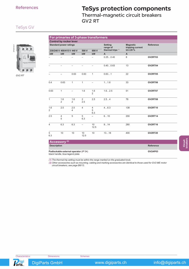
For primaries of 3-phase transformersControl by rocker leverStandard power ratings Setting
range of thermal trips (1)
Magnetic tripping current Id ± 20 %
Reference
230/240 V 400/415 V 440 V 500 V 690 VkW kW kW kW kW A A
– – – – – 0.25…0.40 8 GV2RT03
– – – – – 0.40…0.63 13 GV2RT04
– – 0.63 0.63 1 0.63…1 22 GV2RT05
0.4 0.63 1 1 – 1…1.6 33 GV2RT06
0.63 1 – 1.6 1.62
1.6…2.5 51 GV2RT07
1 1.62
1.62
22.5
2.5 2.5…4 78 GV2RT08
1.62
2.5 2.54
4 456.3
4…6.3 138 GV2RT10
2.5 45
5 56.3
– 6…10 200 GV2RT14
4 6.3 6.3 – 1012.5
9…14 280 GV2RT16
56.3
10 10 1012.5
10 13…18 400 GV2RT20
Accessory (2)
Description Reference
Padlockable external operator (IP 54) black handle, blue legend plate
GV2AP03
(1) The thermal trip setting must be within the range marked on the graduated knob.(2) Other accessories such as mounting, cabling and marking accessories are identical to those used for GV2 ME motor
circuit breakers, see page B6/13.
TeSys protection components Thermal-magnetic circuit breakers GV2 RT
GV2 RT
DF5
2614
2.tif
Characteristics:page B6/51
Dimensions:page B6/75
Schemes:page B6/82
[email protected] GmbH

B6/10
GV2 AK00GV1 L3
GV AD
GV AM11
GV AM11
GV AN
GV AN
GV2 P
GV2 ME
GV AX
GV AU
GV AS
GV AE1
GV AE1
GV AE11, GV AE20
GV2 L
GV2 LE
DF5
2634
0.ep
s
[email protected] GmbH

B6/11
Cir
cuit
b
reak
ers
TeSys GV
Contact blocksDescription Mounting Maximum
numberType of contacts
Sold in lots of
Unit reference
Instantaneous auxiliary contacts
Front (1) 1 N/O or N/C (2) 10 GVAE1N/O + N/C 10 GVAE11N/O + N/O 10 GVAE20
Side (LH)
2 N/O + N/C 1 GVAN11N/O + N/O 1 GVAN20
Fault signalling contact + instantaneous auxiliary contact
Side (3)
(LH)1 N/O (fault) + N/O 1 GVAD1010
+ N/C 1 GVAD1001N/C (fault) + N/O 1 GVAD0110
+ N/C 1 GVAD0101Short-circuit signalling contact
Side (LH)
1 C/O common point 1 GVAM11
Electric tripsMounting Voltage Reference
Undervoltage or shunt trips (4)
Side (1 block on RH side of circuit breaker)
24 V 50 Hz GVAp02560 Hz GVAp026
48 V 50 Hz GVAp05560 Hz GVAp056
100 V 50 Hz GVAp107100…110 V 60 Hz GVAp107110…115 V 50 Hz GVAp115
60 Hz GVAp116120…127 V 50 Hz GVAp125127 V 60 Hz GVAp115200 V 50 Hz GVAp207200…220 V 60 Hz GVAp207220…240 V 50 Hz GVAp225
60 Hz GVAp226380…400 V 50 Hz GVAp385
60 Hz GVAp386415…440 V 50 Hz GVAp415415 V 60 Hz GVAp416440 V 60 Hz GVAp385480 V 60 Hz GVAp415500 V 50 Hz GVAp505600 V 60 Hz GVAp505
Undervoltage trip, INRS (can only be mounted on GV2 ME) Safety device for dangerous machines conforming to INRS and VDE 0113
Side (1 block on RH side of circuit breaker GV2 ME)
110…115 V 50 Hz GVAX11560 Hz GVAX116
127 V 60 Hz GVAX115220…240 V 50 Hz GVAX225
60 Hz GVAX226380…400 V 50 Hz GVAX385
60 Hz GVAX386415…440 V 50 Hz GVAX415440 V 60 Hz GVAX385
Add-on contact blocksDescription Mounting Maximum
numberReference
Visible isolation block (5) Front (1) 1 GV2AK00 (6)
Limiters At top (GV2 ME and GV2 P)
1 GV1L3
Independent 1 LA9LB920
(1) Mounting of a GV AE contact block or a GV2 AK00 visible isolation block on GV2 P and GV2 L.(2) Choice of N/C or N/O contact operation, depending on which way round the reversible block is mounted.(3) The GV AD is always mounted next to the circuit breaker.(4) To order an undervoltage trip: replace the dot (p) in the reference with a U, example: GV AU025.
To order a shunt trip: replace the dot (p) in the reference with an S, example: GV AS025.(5) Visible isolation of the 3 poles upstream of circuit breaker GV2 P and GV2 L.
Visible isolation block GV2 AK00 cannot be used with motor circuit breakers GV2 P32 and GV2 L32 (Ith max = 25 A).(6) Ie Max = 32 A.
References TeSys protection componentsThermal-magnetic and magnetic motor circuit breakers GV2 with screw clamp connectionsAdd-on blocks and accessories
Characteristics:pages B6/89 and B6/94
Dimensions, schemes:pages B6/70 to B6/82
LA9LB920
DF5
3743
2R.e
ps
GV1L3
[email protected] GmbH


B6/13
Cir
cuit
b
reak
ers
TeSys GV
AccessoriesDescription Application Sold in
lots of Unit reference
Adapter plates For mounting a GV2 ME or GV2 LE by screw fixing
10 GV2AF02
For mounting a GV2 ME or GV2 P and contactor LC1 D09…D38 with front faces aligned
1 LAD311
Height compensation plate 7.5 mm 10 GV1F03Combination blocks Between GV2 and contactor LC1 K or LP1 K 10 GV2AF01
Between GV2 and contactor LC1 D09…D38 10 GV2AF3Between GV2 mounted on LAD 311 and contactor LC1 D09…D38
10 GV2AF4
Motor starter adapter plate With 3-pole connection for mounting a GV2 and a contactor LC1 D09…D25
1 GK2AF01
Description Application Pitch Referencemm
Sets of 3-pole 63 A busbars
2 tap-offs 45 GV2G24554 GV2G25472 GV2G272
3 tap-offs 45 GV2G34554 GV2G354
4 tap-offs 45 GV2G44554 GV2G45472 GV2G472
5 tap-offs 54 GV2G554
Description Application Sold in lots of
Unit reference
Protective end cover For unused busbar outlets 5 GV1G10
Terminal block for supply to one or more GV2 G busbar sets
Connection from the top 1 GV1G09Can be fitted with current limiter GV1 L3 (GV2 ME and GV2 P)
1 GV2G05
Cover for terminal block For mounting in modular panels 10 LA9E07
Flexible 3-pole connection for connecting a GV2 to a contactor LC1-D09…D25
Centre distance between mounting rails: 100…120 mm
10 GV1G02
Set of connections upstream/downstream
For connecting GV2 ME to a printed circuit board 10 GV2GA01
“Large Spacing” adapter UL 508 type E
For GV2 PppH7 (except 32 A) 1 GV2GH7
Clip-in marker holders (supplied with each circuit breaker)
For GV2 P, GV2 L, GV2 LE and GV2 RT (8 x 22 mm)
100 LA9D92
References TeSys protection componentsThermal-magnetic and magnetic motor circuit breakers GV2 with screw clamp connectionsAccessories
Dimensions, schemes:pages B6/70 to B6/82
DB
4179
42.e
ps
GV1 G09
[email protected] GmbH

B6/14
TeSys GV
1DB
1266
31.e
ps
5
3
2
4
DB
1266
30.e
ps
6
DB
1266
32.e
ps
7
PB10
6297
_45.
eps
Extended Rotary HandleAllows a circuit breaker or a starter-controller installed in back of an enclosure to be operated from the front of the enclosure.A rotary handle can be black or red/yellow, IP54 or IP65. It includes a function for locking the circuit breaker or the starter in the O (Off) or I (On) position (depending of the type of rotary handle) by means of up to 3 padlocks with a shank diameter of 4 to 8 mm. The extended shaft must be adjusted to use in different size enclosures. The IP54 rotary handle is fixed with a nut (Ø22) to make easier the assembling. The new Laser Square tool brings the accuracy to align the circuit breaker and the rotary handle.
Padlockable external operators for GV2P and GV2LDescription
1 Kit handle + mounting system2 Universal handle3 Shaft4 Bracket5 Shaft support plate for deep enclosure6 Retrofit accessory7 Laser Square accessory
Kit handle + mounting systemDescription Item Reference
For GV2 P/L Black handle, front plate, with trip status, IP 54 1 GV2APN01
Red handle, front plate, with trip status, IP 54 1 GV2APN02Red handle, front plate, without trip status, IP 65 1 GV2APN04
For GV2 LE Padlocking in “On” and “Off” position Black handle, blue front plate, IP 54
- GV2AP03
Universal handleFor GV2 P/L Black handle, IP 54 2 GVAPB54
Red handle, IP 54 2 GVAPR54Red handle, IP 65 2 GVAPR65
ShaftFor GV2 P/L L = 315 mm 3 GVAPA1Bracket
For GV2 P/L 4 GVAPH02Shaft support plate for deep enclosure
For GV2 P/L Depth u 250 mm 5 GVAPK11Retrofit accessory
For GV2 P/L 6 GVAPP1Laser Square accessory
For GV2 P/L 7 GVAPL01Sticker Sold in lots of
Warning label For French 10 - GVAPSFRFor English 10 - GVAPSENFor German 10 - GVAPSDEFor Spanish 10 - GVAPSESFor Chinese 10 - GVAPSCNFor Portuguese 10 - GVAPSPTFor Russian 10 - GVAPSRUFor Italian 10 - GVAPSIT
Padlocking deviceDescription Reference
For all GV2 device
For use with up to 4 padlocks, Ø6 mm shank max. (padlocks not included)
GV2V03
References TeSys protection componentsThermal-magnetic and magnetic motor circuit breakers GV2 with screw clamp connections
[email protected] GmbH


B6/16
GV AM11
GV AM11
GV AE1
GV AE1
GV AE11, GV AE20,
GV3 L
GV3 P
GV3 G364
GV AE113, GV AE203, GV AED 1013, GV AED 0113
GV AED 101, GV AED 011
GV2 V03
GV3 G264
GV3 APN02
DB
1266
35.e
ps
[email protected] GmbH

B6/17
Cir
cuit
b
reak
ers
TeSys GV
Contact blocksDescription Mounting Maximum
numberType of contacts
Sold in lots of
Unit reference
Instantaneous auxiliary contacts
Front 1 N/O or N/C (1) 10 GVAE1N/O + N/C 10 GVAE11 (2)
N/O + N/O 10 GVAE20 (2)
Side (LH)
2 N/O + N/C 1 GVAN11 (2)
N/O + N/O 1 GVAN20 (2)
Fault signalling contact + instantaneous auxiliary contact
Front 1 N/O (fault) + N/O 1 GVAED101 (2)
N/O (fault) + N/C 1 GVAED011 (2)
Side (3)
(LH)1 N/O (fault) + N/O 1 GVAD1010
+ N/C 1 GVAD1001N/C (fault) + N/O 1 GVAD0110
+ N/C 1 GVAD0101Short-circuit signalling contact Side (LH) 1 C/O common point 1 GVAM11
Electric trips - undervotlage or shunt (4)
Mounting Voltage Reference
Side (1 block on RH side of circuit breaker)
24 V 50 Hz GVAp02560 Hz GVAp026
48 V 50 Hz GVAp05560 Hz GVAp056
100 50 Hz GVAp107100…110 V 60 Hz GVAp107110…115 V 50 Hz GVAp115
60 Hz GVAp116120…127 V 50 Hz GVAp125127 V 60 Hz GVAp115200 V 50 Hz GVAp207200…220 V 60 Hz GVAp207220…240 V 50 Hz GVAp225
60 Hz GVAp226380…400 V 50 Hz GVAp385
60 Hz GVAp386415…440 V 50 Hz GVAp415415 V 60 Hz GVAp416440 V 60 Hz GVAp385480 V 60 Hz GVAp415500 V 50 Hz GVAp505600 V 60 Hz GVAp505
AccessoriesDescription Reference
Sets of 3-pole 115 A busbarsPitch: 64 mm
2 tap-off GV3 Ppp and GV3 Lpp GV3G2643 tap-off GV3 Ppp and GV3 Lpp GV3G364
Cover “Large Spacing” UL 508 type E(Only one cover required on supply side)
GV3 Ppp GV3G66
(1) Choice of N/C or N/O contact operation, depending on which way round the reversible block is mounted.(2) Contact blocks available in version with spring terminal connections. Add a figure 3 at the end of the references selected above.
Example: GV AED101 becomes GV AED1013.(3) The GV ADpp is always mounted next to the circuit breaker.(4) To order an undervoltage trip: replace the dot (p) in the reference with a U, example: GV AU025.
To order a shunt trip: replace the dot (p) in the reference with an S, example: GV AS025.
References TeSys protection componentsThermal-magnetic motor circuit breakers GV3 P and GV3 LAdd-on blocks and accessories
GV3 G66
DF5
3742
4.ep
s
[email protected] GmbH

B6/18
TeSys GV
1
DB
1266
37.e
ps
5
3 2
4
DB
1266
36.e
ps
6
DB
1266
32.e
ps
7
PB10
6297
_45.
eps
Extended Rotary HandleAllows a circuit breaker or a starter-controller installed in back of an enclosure to be operated from the front of the enclosure.A rotary handle can be black or red/yellow, IP54 or IP65. It includes a function for locking the circuit breaker or the starter in the O (Off) or I (On) position (depending of the type of rotary handle) by means of up to 3 padlocks with a shank diameter of 4 to 8 mm. The extended shaft must be adjusted to use in different size enclosures. The IP54 rotary handle is fixed with a nut (Ø22) to make easier the assembling. The new Laser Square tool brings the accurency to align the circuit breaker and the rotary handle.
Padlockable external operators for GV3 and GV3LDescription
1 Kit handle + mounting system2 Universal handle3 Shaft4 Bracket5 Shaft support plate for deep enclosure6 Retrofit accessory7 Laser Square accessory
Kit handle + mounting systemDescription Item Reference
For GV3 P/L Black handle, front plate, with trip status, IP 54 1 GV3APN01Red handle, front plate, with trip status, IP 54 1 GV3APN02Red handle, front plate, without trip status, IP 65 1 GV3APN04
Universal handleFor GV3 P/L Black handle, IP 54 2 GVAPB54
Red handle, IP 54 2 GVAPR54Red handle, IP 65 2 GVAPR65
ShaftFor GV3 P/L L = 315 mm 3 GVAPA1Bracket
For GV3 P/L 4 GVAPH03Shaft support plate for deep enclosure
For GV3 P/L Depth u 300 mm 5 GVAPK12Retrofit accessory
For GV3 P/L 6 GVAPP1Laser Square accessory
For GV3 P/L 7 GVAPL01Sticker Sold in lots of
Warning label For French 10 - GVAPSFRFor English 10 - GVAPSENFor German 10 - GVAPSDEFor Spanish 10 - GVAPSESFor Chinese 10 - GVAPSCNFor Portuguese 10 - GVAPSPTFor Russian 10 - GVAPSRUFor Italian 10 - GVAPSIT
References TeSys protection componentsThermal-magnetic motor circuit breakers GV3 P and GV3 L
[email protected] GmbH


B6/21
Cir
cuit
b
reak
ers
TeSys GV
For thermal-magnetic motor circuit breakers GV3 ME80Contact blocksDescription Type of standard
early break contactsReference
Instantaneous auxiliary contact blocks (1 per circuit breaker)
N/C + N/O GV3A01N/O + N/O GV3A02N/C + N/O + N/O GV3A03N/O + N/O + N/O GV3A05N/O + N/O + 2 volt-free terminals GV3A06N/C + N/O + 2 volt-free terminals GV3A07
Fault signalling contacts (1) N/C GV3A08N/O GV3A09
Electric tripsDescription Voltages Reference
50 Hz 60 HzUdervoltage trips (1) 110, 120, 127 V 120, 127 V GV3B11
220, 240 V 277 V GV3B22380, 415 V 440 V, 480 V GV3B38
Shunt trips (1) 110, 120, 127 V 120, 127 V GV3D11220, 240 V 277 V GV3D22380, 415 V 440 V, 480 V GV3D38
AccessoryDescription Sold in
lots ofUnit reference
Padlocking device, for locking the Start button (on open-mounted product)
5 GV1V02
For magnetic circuit breaker GK3 EF80Contact blocksDescription Number of poles Reference
Auxiliary contact blocks for On-Off signalling and “control circuit test” function (1 or 2 blocks per device) mounted on RH side of GK3 EF80
N/O GK2AX10N/O + N/O GK2AX20N/C + N/O GK2AX50
Instantaneous fault signalling contact blocks (1 or 2 blocks per device) mounted on LH side of GK3 EF80
N/O GK2AX12N/O + N/O GK2AX22N/C + N/O GK2AX52
AccessoriesDescription Reference
Padlocking device for padlocking the operator, using up to 3 padlocks (padlocks to be ordered separately)
GK3AV01
External operator for mounting on enclosure door. Red Ø40 knob on yellow plate, padlockable in position O (with up to 3 padlocks). Door locked when knob in position I, and when knob padlocked in position O.
GK3AP03
(1) 1 voltage trip OR 1 fault signalling contact to be fitted inside the motor circuit breaker.
Other versions
24 to 690 V, 50 or 60 Hz voltage trips for circuit breakers GV3 ME80.Please consult your Regional Sales Office.
References TeSys protection componentsMotor circuit breakers GV3 ME80 and GK3 EF80Add-on blocks and accessories
Characteristics:pages B6/89 and B6/92
Dimensions:page B6/47
[email protected] GmbH


B6/23
Cir
cuit
b
reak
ers
TeSys GV
Add-on auxiliary contactsThese allow remote indication of the circuit breaker contact states. They can be used for signalling, electrical locking, relaying, etc. They are available in two versions: standard and low level. They include a terminal block and the auxiliary circuits leave the circuit breaker through a hole provided for this purpose.They perform the following functions, depending on where they are located in the circuit breaker:
Location Function Application1 and/or 4 C/O contact Indicates the position of the circuit breaker poles2 Trip indication Indicates that the circuit breaker has tripped due to an
overload, a short-circuit, a differential fault or the operation of a voltage trip (undervoltage or shunt trip), or of the “push to trip” test button. It resets when the circuit breaker is reset.
3 Electrical fault indication Indicates that the circuit breaker has tripped due to an overload, a short-circuit or a differential fault. It resets when the circuit breaker is reset.
Type Reference
Standard GV7AE11
Low level GV7AB11
Fault discrimination devicesThese make it possible to:b either differentiate a thermal fault from a magnetic fault,b or open the contactor only in the event of a thermal fault.
Voltage Reference
a 24...48 and c 24…72 V GV7AD111 (1)
z 110…240 V GV7AD112 (1)
Electric tripsThese allow the circuit breaker to be tripped via an electrical control signal.
b Undervoltage trip GV7 AUv Trips the circuit breaker when the control voltage drops below the tripping threshold, which is between 0.35 and 0.7 times the rated voltage.v Circuit breaker closing is only possible if the voltage exceeds 0.85 times the rated voltage. Circuit breaker tripping by a GV7 AU trip meets the requirements of IEC 60947-2.
b Shunt trip GV7 ASTrips the circuit breaker when the control voltage rises above 0.7 times the rated voltage.
b Operation (GV7 AU or GV7 AS)v When the circuit breaker has been tripped by a GV7 AU or AS, it must be reset either locally or by remote control. (For remote control, please consult your Regional Sales Office).v Tripping has priority over manual closing: if a tripping instruction is present, manual action does not result in closing, even temporarily, of the contacts.v Durability: 50 % of the mechanical durability of the circuit breaker.
Type Voltage Reference
Undervoltage trip 48 V, 50/60 Hz GV7AU055 (1)
110…130 V, 50/60 Hz GV7AU107 (1)
200…240 V, 50/60 Hz GV7AU207 (1)
380…440 V, 50/60 Hz GV7AU387 (1)
525 V, 50 Hz GV7AU525 (1)
Shunt trip 48 V, 50/60 Hz GV7AS055 (1)
110…130 V, 50/60 Hz GV7AS107 (1)
200…240 V, 50/60 Hz GV7AS207 (1)
380…440 V, 50/60 Hz GV7AS387 (1)
525 V, 50 Hz GV7AS525 (1)
(1) For mounting of a GV7 AD or a GV7 AU or AS.
References TeSys protection componentsThermal-magnetic motor circuit breakers GV7 R with screw clamp connectionsAdd-on blocks and accessories
Characteristics:pages B6/51, B6/52 and B6/56
Dimensions:pages B6/79 to B6/81
Schemes:page B6/83
[email protected] GmbH

B6/24
ON
OFFO
ON
OFFO
ON
OFFO
OFFO
ON
ON
OFFO
GV7 RE, RS
GV7 AP03
OFFO
ON
GV7 AP04
GV7 AP01, AP02
GV7 V01
GV7 AP05
GV7 RE, RS
GV7 AC01
GV7 AC03 GV7 AC01
GV7 AC04
GV7 AC04
DF5
2634
3.ep
s
[email protected] GmbH

B6/25
Cir
cuit
b
reak
ers
TeSys GV
Cabling accessoriesDescription Application For use on
contactorsSold in lots of
Unit reference
Clip-on connectors for GV7 R
Up to 150 A, 1.5…95 mm2 – 3 GV7AC021
Up to 220 A, 1.5…185 mm2 – 3 GV7AC022
Spreader 3-pole (1)
To increase the pitch to 45 mm – 1 GV7AC03
Terminal shields IP 405 (1)
Supplied with sealing accessory
– 1 GV7AC01
Phase barriers Safety accessories used when fitting of shields is impossible
– 2 GV7AC04
Insulating screens Ensure insulation between the connections and the backplate
– 2 GV7AC05
Kits for combination with contactor (2)
Allowing link between the circuit breaker and the contactor. The cover provides protection against direct finger contact
LC1 F115…F185 1 GV7AC06
LC1 F225 and F265 1 GV7AC07
LC1 D115 and D150 1 GV7AC08
Direct rotary handleReplaces the circuit breaker front cover; secured by screws. It includes a device for locking the circuit breaker in the O (Off) position by means of up to 3 padlocks with a shank diameter of 5 to 8 mm (padlocks not included). A conversion accessory allows the direct rotary handle to be mounted on the enclosure door. In this case, the door cannot be opened if the circuit breaker is in the “ON” position. Circuit breaker closing is inhibited if the enclosure door is open.
Description Type Degree of protection
Reference
Direct rotary handle Black handle, black legend plate IP 40 GV7AP03
Red handle, yellow legend plate IP 40 GV7AP04
Adapter plate (3) Four mounting direct rotary handle on enclosure door
IP 43 GV7AP05
Extended rotary handleAllows a circuit breaker installed in the back of an enclosure to be operated from the front of the enclosure. It comprises:b a unit which screws onto the front cover of the circuit breaker,b an assembly (handle and front plate) to be fitted on the enclosure door,b an extension shaft which must be adjusted (distance between the mounting surface and the door: 185 mm minimum, 600 mm maximum). It includes a device for locking the circuit breaker in the O (Off) position by means of up to 3 padlocks with a shank diameter of 5 to 8 mm (padlocks not included). This prevents the enclosure door from being opened.
Description Type Degree of protection
Reference
Extended rotary handle Black handle, black legend plate IP 55 GV7AP01
Red handle, yellow legend plate IP 55 GV7AP02
Locking deviceAllows circuit breakers not fitted with a rotary handle to be locked in the O (Off) position by means of up to 3 padlocks with a shank diameter of 5 to 8 mm (padlocks not included).
Description Application Reference
Locking device For circuit breaker not fitted with a rotary handle GV7V01
(1) Terminal shields cannot be used together with spreaders.(2) The kit comprises links, a protective shield and a depth adjustable metal bracket for the breaker.(3) This conversion accessory makes it impossible to open the door if the device is closed and prevents the device from being
closed if the door is open.
References TeSys protection componentsThermal-magnetic motor circuit breakers GV7 R with screw clamp connectionsAccessories
GV7 AC07
+
+
DF5
3742
9.ep
s
GV7 AC08
+
DF5
3742
8.ep
s
Dimensions:pages B6/79 to B6/81
[email protected] GmbH