ontology dynamics for semantic web: the momis approach …dbgroup.unimo.it/tesi/fergnani.pdf ·...
TRANSCRIPT

UNIVERSITA DEGLI STUDI DI MODENA
E REGGIO EMILIA
Facolta di Ingegneria - Sede di Modena
Corso di Laurea in Ingegneria Informatica
Ontology dynamics for Semantic Web:
the MOMIS approach
Dinamica delle ontologie per il
Web Semantico: l’approccio di MOMIS
Relatore Tesi di Laurea diChiar.mo Prof. Sonia Bergamaschi Alain Fergnani
Correlatore ControrelatoreDott. Ing. Francesco Guerra Chiar.mo Prof. Paolo Tiberio
Anno Accademico 2001 - 2002


Key words:Semantic Web
OntologyDynamicsMOMIS
SEWASIE


RINGRAZIAMENTI
Desidero ringraziare la Professoressa Sonia Bergamaschi, l’Ing. FrancescoGuerra, l’Ing. Maurizio Vincini e il Professore Domenico Beneventano perl’aiuto fornito durante la realizzazione della presente tesi.Ringrazio inoltre l’A.C. che mi ha permesso di avere sempre una buonascusa per staccare dallo studio.Un ringraziamento speciale va poi alla mia famiglia che mi ha permesso diraggiungere questo importante obiettivo e alla mia fidanzata, Letizia, che miha sempre sostenuto e sopportato in questi anni di studi.


Contents
Abstract ix
Introduction 1
1 The Semantic Web 51.1 What is the Semantic Web? . . . . . . . . . . . . . . . . . . . 61.2 Knowledge representation . . . . . . . . . . . . . . . . . . . . 71.3 Ontologies . . . . . . . . . . . . . . . . . . . . . . . . . . . . . 81.4 Agents . . . . . . . . . . . . . . . . . . . . . . . . . . . . . . . 9
2 SEWASIE and MOMIS 112.1 SEWASIE . . . . . . . . . . . . . . . . . . . . . . . . . . . . . 11
2.1.1 Overview . . . . . . . . . . . . . . . . . . . . . . . . . 112.1.2 The Business Scenario . . . . . . . . . . . . . . . . . . 122.1.3 The SEWASIE architecture . . . . . . . . . . . . . . . 13
2.2 MOMIS . . . . . . . . . . . . . . . . . . . . . . . . . . . . . . 152.2.1 Overview . . . . . . . . . . . . . . . . . . . . . . . . . 152.2.2 The MOMIS approach . . . . . . . . . . . . . . . . . . 172.2.3 The architecture . . . . . . . . . . . . . . . . . . . . . 17
3 Ontologies 213.1 Definitions . . . . . . . . . . . . . . . . . . . . . . . . . . . . . 213.2 Modelling primitives . . . . . . . . . . . . . . . . . . . . . . . 243.3 Ontologies classification . . . . . . . . . . . . . . . . . . . . . 253.4 Ontology dynamics – different approaches . . . . . . . . . . . 30
3.4.1 Evolution approach . . . . . . . . . . . . . . . . . . . . 32Change Representation . . . . . . . . . . . . . . . . . . 33Semantics of Change . . . . . . . . . . . . . . . . . . . 34Change Implementation . . . . . . . . . . . . . . . . . 35Change Propagation . . . . . . . . . . . . . . . . . . . 35
3.4.2 Versioning approach . . . . . . . . . . . . . . . . . . . 36
i

ii CONTENTS
Analysis of compatibility . . . . . . . . . . . . . . . . . 37Requirements for versioning framework . . . . . . . . . 39Identification . . . . . . . . . . . . . . . . . . . . . . . 40Change specification and transparent evolution . . . . 41
4 Ontology management – tools and projects 434.1 Sources integration with SI-Designer . . . . . . . . . . . . . . 43
4.1.1 Generation of the Common Thesaurus . . . . . . . . . 45The WordNet lexical system . . . . . . . . . . . . . . . 46
4.1.2 Generation of the Global Schema . . . . . . . . . . . . 47Cluster generation . . . . . . . . . . . . . . . . . . . . 48Global class generation . . . . . . . . . . . . . . . . . . 48
4.1.3 The MOMIS ontology . . . . . . . . . . . . . . . . . . 494.2 Requirements for ontologies editors . . . . . . . . . . . . . . . 51
Functional requirement . . . . . . . . . . . . . . . . . . 52User’s supervision requirement . . . . . . . . . . . . . . 53Transparency requirement . . . . . . . . . . . . . . . . 54Reversibility requirement . . . . . . . . . . . . . . . . . 54Auditing requirement . . . . . . . . . . . . . . . . . . . 54Ontology refinement requirement . . . . . . . . . . . . 55Usability requirement . . . . . . . . . . . . . . . . . . . 56
4.3 Comparison of ontologies tools . . . . . . . . . . . . . . . . . . 564.3.1 Ontology development tools . . . . . . . . . . . . . . . 56
OILEd . . . . . . . . . . . . . . . . . . . . . . . . . . . 57OntoEdit . . . . . . . . . . . . . . . . . . . . . . . . . 57Protege-2000 . . . . . . . . . . . . . . . . . . . . . . . 58WebODE . . . . . . . . . . . . . . . . . . . . . . . . . 60Comments . . . . . . . . . . . . . . . . . . . . . . . . . 61
4.3.2 Ontology merge and integration tools . . . . . . . . . . 62Chimaera . . . . . . . . . . . . . . . . . . . . . . . . . 63PROMPT . . . . . . . . . . . . . . . . . . . . . . . . . 64ODEMerge . . . . . . . . . . . . . . . . . . . . . . . . 66FCA-Merge . . . . . . . . . . . . . . . . . . . . . . . . 67Comments . . . . . . . . . . . . . . . . . . . . . . . . . 68
4.3.3 Conclusion . . . . . . . . . . . . . . . . . . . . . . . . . 69
5 Integration of new sources in the MOMIS system 735.1 The static environment of MOMIS . . . . . . . . . . . . . . . 735.2 The problems faced . . . . . . . . . . . . . . . . . . . . . . . . 755.3 A first attempt . . . . . . . . . . . . . . . . . . . . . . . . . . 775.4 The proposed solution . . . . . . . . . . . . . . . . . . . . . . 81

CONTENTS iii
5.4.1 Global Schema annotation . . . . . . . . . . . . . . . . 82Global Classes’ annotation . . . . . . . . . . . . . . . . 82Global Attributes’ annotation . . . . . . . . . . . . . . 87
5.4.2 The new integration process . . . . . . . . . . . . . . . 895.5 Necessary changes . . . . . . . . . . . . . . . . . . . . . . . . . 945.6 Critical analysis of the proposed process . . . . . . . . . . . . 95
6 Semantic Web projects 976.1 W3C Consortium . . . . . . . . . . . . . . . . . . . . . . . . . 98
6.1.1 OWL Web Ontology Language . . . . . . . . . . . . . 996.2 OntoWeb . . . . . . . . . . . . . . . . . . . . . . . . . . . . . 1026.3 On-To-Knowledge . . . . . . . . . . . . . . . . . . . . . . . . . 1056.4 MAFRA . . . . . . . . . . . . . . . . . . . . . . . . . . . . . . 1146.5 SHOE . . . . . . . . . . . . . . . . . . . . . . . . . . . . . . . 1176.6 Comments . . . . . . . . . . . . . . . . . . . . . . . . . . . . . 120
Conclusions 123
A The running example 127
B The ODLI3 description language 147
C Links 151
Bibliography 158


List of Figures
2.1 The SEWASIE Virtual Network . . . . . . . . . . . . . . . . . 142.2 MOMIS prototype architecture . . . . . . . . . . . . . . . . . 18
3.1 Four elementary phases of ontology evolution process . . . . . 333.2 Ontology Evolution Process . . . . . . . . . . . . . . . . . . . 363.3 Two examples of prospective and retrospective use of ontologies 38
4.1 SI-Designer Architecture. . . . . . . . . . . . . . . . . . . . . . 44
5.1 The Common Thesaurus transformation. . . . . . . . . . . . . 775.2 The new integration process. . . . . . . . . . . . . . . . . . . . 895.3 Lexical problems. . . . . . . . . . . . . . . . . . . . . . . . . . 91
6.1 On-To-Knowledge architecture . . . . . . . . . . . . . . . . . . 1076.2 Spectacle Cluster Map Viewer. . . . . . . . . . . . . . . . . . . 1096.3 MAFRA conceptual architecture . . . . . . . . . . . . . . . . . 115
A.1 Reference example . . . . . . . . . . . . . . . . . . . . . . . . 128A.2 Cluster generation tab. . . . . . . . . . . . . . . . . . . . . . . 135A.3 Global Attributes refinement. . . . . . . . . . . . . . . . . . . 142
v


List of Tables
3.1 Composite changes in the ontology . . . . . . . . . . . . . . . 343.2 Categorization of compatibility . . . . . . . . . . . . . . . . . 38
5.1 Global Class annotation rules. . . . . . . . . . . . . . . . . . . 865.2 New mapping table example. . . . . . . . . . . . . . . . . . . . 93
vii


Abstract
Nowadays the Web is a huge collection of information and its expansion rateis very high. The users need new ways to exploit all this available informa-tion and possibilities. The problem is that Web information is meaninglessfor a computer and so it is very hard to find out what we are looking for.The Semantic Web is the new challenge of web using. Its goal is tobring structure and semantics to the content of Web pages, creating an en-vironment where software agents, roaming from page to page, can carry outsophisticated tasks for users.In consequence of this new vision of the Web many research groups began tostudy related problems. One of the most important seems to be the Ontolo-gies management. In fact, Ontologies are considered as a key component tobuild the Semantic Web.The present work explains the new scenario of the Semantic Web by meansof the numerous projects involved (mainly W3C). Moreover, we present someprojects related to the ontology issue and, in particular, the ontologies dy-namics problem.In this scenario we present SEWASIE (SEmantic Webs and AgentS inIntegrated Economies), a new project funded by the UE and led by theModena and Reggio Emilia University. Finally we explain the relevance ofthe MOMIS (Mediator envirOnment for Multiple Information Sources)system, an Intelligent Information Integration system developed at the Uni-versity of Modena and Reggio Emilia, and in particular the attempts to solvethe problems of managing dynamic aspects in an ontology.
ix


Introduction
The current WWW is an enormous amount of documents and informationand its growing rate is very high. Besides, more and more users and busi-nesses have access to the Web and want to find what they need in a shorttime. In the last few years the rapid increase in the available informationhas complicated the search of documents and web pages semantically richfor users. In fact, if on one hand internet search engines are fundamentalfor retrieving information, on the other hand the search results are oftenmeaningless and completely out of the domain users are interested in. More-over from the business point of view, it is more and more difficult to keeptheir data updated and to make them available for clients in the right format.
In this context arises the need for a new vision of the Web; its inventorTim Berners-Lee has called it The Semantic Web [1]. Berners-Lee, thathas also built the infrastructure of the current web, has imagined aWeb whereresources could be annotated with machine-processable metadata providingthem with background knowledge and meaning. Moreover this annotationcould be exploited by users’ agents, that can carry out sophisticated tasksand searches roaming from page to page.
This new scenario creates many expectations among the users and infor-mation providers but new issues and new problems have to be solved beforeachieving good results. Thus universities, private research groups, enterprisesbegan to study possible solutions. One of the main issue in this context is“dynamics”. Web environment is very changeable, it is continuously up-dated, modified and the users need to rely on the data they retrieve from thenet. Another fundamental component seems to be ontology; this “explicitspecification of a conceptualization” [2] lets information providers annotatingtheir domains. The annotation phase is a crucial step in order to create asemantically rich environment exploitable and intelligible by users’ agents.Many studies are trying to find languages and standards that can help do-main experts in the delicate task of expressing their knowledge in a formal
1

way. But as in the case of data, ontologies evolve, and therefore we have toface again the problem of managing the dynamics with respect to ontolo-gies.
Another important aspect to be considered in this context is: sources in-tegration. Today the ability to integrate, merge, manipulate heterogeneoussources is fundamental; companies merge their departments, doctors gathertheir data, vendors want to create common market places, etc.
It is clear by now that the problem is really complicated and it results in alot of related implications, such as: information retrieval and integration, se-mantic enrichment and dynamics management. For these reasons, the mainpurpose of this work is: first, to better understand how international researchprojects face the mentioned problems; second to study the state of the art ofthe tools for ontologies management, in order to acquire important knowl-edge for the solution of our problem, and finally to elaborate a solution toeffectively manage the insertion of new sources in the context of the MOMISsystem, which is the intelligent information integration system developed atthe University of Modena and Reggio Emilia.
Main organization of this dissertation.
Chapter 1This chapter introduces the Semantic Web with a typical scenario of thenew WWW.
Chapter 2The SEWASIE (SEmantic Webs and AgentS in Integrated Economies) projectis presented; its main objectives, features and architecture are introduced.The second part of the chapter is dedicated to explain the MOMIS (Media-tor envirOnment for Multiple Information Sources) system; in particular thesemantic MOMIS approach to sources integration and the developed archi-tecture of the framework are explained.
Chapter 3This chapter describes the important role of “ontologies” in Semantic Web.Many definitions and classifications are presented. The fundamental problemof the ontology dynamics is taken into consideration describing two possibleapproach: evolution and versioning.
Chapter 4
2

We dedicate this chapter to explore the main tools and projects for ontologymanagement. We define the principal requirements for ontologies’ editors,and we review the principal tools for developing and integrating ontologies.Moreover, we present SI-Designer (the GUI of the MOMIS system for theintegration process) that is the MOMIS tool for building and manage an on-tology.
Chapter 5This chapter, starting from the MOMIS approach, presents the core contri-bution of this dissertation, i.e. the extension of the MOMIS approach for themanagement of the dynamics of an ontology.
Chapter 6The last chapter describes some of the most important Semantic Web projects.We present also some new languages (OWL and SHOE) for the managementof ontologies.
Finally we give some remarks in chapter Conclusions and Future Works,a complete running example in Appendix A and the principal features ofODLI3 language in Appendix B. Appendix C gathers the links present withinthis thesis.
3


Chapter 1
The Semantic Web
In this chapter we will present the new scenario introduced by a new visionof the web: the Semantic Web. A fundamental paper about the SemanticWeb is the one written by J. Hendler, O. Lassila and T. Berners-Lee that ap-peared on Scientific America in 2001 [1]. The authors depicted a new “world”where people interoperate with their electronic devices in a completely dif-ferent way from today. They imagine that, for instances, you could be atthe doctor’s office and you have to book a series of therapy sessions but youalready have some appointments. You can instruct your Semantic Web agentthrough your handheld Web browser. You can set up the search to find onlyplaces within a 20-km radius of your home and only in a specific time of theday. The agent, then, starts to look for information interacting with otheragents present on the web sites of the doctors in the area. In few minutesthe agent presents you with a plan; if you like it you can change your weekagenda and mail your tennis trainer that for a month you can not play. Ifyou don’t like the plan you can set up your agent with stricter preferencesand redo the search.
At present the World Wide Web cannot carry out all the tasks of theabove scenario. Most of the Web’s content today is designed for humansinteraction, not for computer programs. Computers can easily parse Webpages for layout and routine processing – a header, a link to another page –but in general they have no reliable way to process the semantics: this is thehome page of my professor and this link goes to the course material page.
This is the reason for which the research area of Semantic Web is ac-tive both at the the European (IST program supports several projects, On-To-Knowledge, SEWASIE, etc.) and American level as it is shown in thefollowing subsections.

6 The Semantic Web
1.1 What is the Semantic Web?
Nowadays the Web is a huge collection of information useful for people butmeaningless for machines without a post-processing. By now the WWWreaches its second version; the first saw the HTML static pages changing thestyle people share information, while the second is the one we are experienc-ing today with dynamic pages created as response to a query on a database.The increasing of available information and of the usage of the Web, arecreating new expectations with the users. In other words it’s time to thinkabout the third version of the WWW: the Semantic Web.The Semantic Web will bring structure to the meaningful content of Webpages, creating an environment where software agents, roaming from page topage, can readily carry out sophisticated tasks for users.Such an agent coming to the professor’s Web page will not just know thatthe page has some keywords such as “ontology, knowledge representation,artificial intelligence” (as might be encoded today) but also that the courseis scheduled for Tuesday and Thursday at 11.00 am. These semantics wereencoded into the Web pages using off-the-shelf software for writing SemanticWeb pages.The Semantic Web is not a separate Web but an extension of the currentone, in which information is given well-defined meaning, better enabling com-puters and people to work in cooperation. The first steps in weaving theSemantic Web into the structure of the existing Web are already under way.In the near future, these developments will introduce new functionality asmachines become much better able to process and “understand” the datathat they merely display at present.The essential property of the World Wide Web is its universality. The powerof a hypertext link is that “anything can link to anything”. Web technology,therefore, does not discriminate between commercial and academic informa-tion, or among cultures, languages, media and so on. Information varies alongmany axes. One of these is the difference between information produced pri-marily for human consumption and that produced mainly for machines. Atone end we have everything from the TV commercial to poetry. At the otherend we have databases, programs and sensor output. Today, the Web hasdeveloped most rapidly as a means of documents for people rather than fordata and information that can be processed automatically. The SemanticWeb aims to build these capabilities. Like the Internet, the Semantic Webwill be as decentralized as possible. Such Web-like systems generate a lotof excitement at every level, from major corporation to individual user, andprovide benefits that are hard or impossible to predict in advance.

1.2 Knowledge representation 7
1.2 Knowledge representation
For the semantic web to function, computers have to be able to access struc-tured collections of information and sets of inference rules that they canuse to conduct automated reasoning. Artificial-intelligence and DataBaseresearchers have studied such systems since long before the Web was devel-oped. Knowledge representation is currently in a state comparable to that ofhypertext before the advent of the Web. Many studies has been conductedin this area but till now there are only some demonstrations of the numerouspotential.Traditional knowledge-representation systems typically have been central-ized, requiring everyone to share exactly the same definition of common con-cepts. But central control is increasing the size and scope of such a systemand rapidly it becomes unmanageable.Semantic Web researchers make the language for the rules as expressive asneeded to allow the Web to reason as widely as desired. The challenge ofthe Semantic Web, therefore, is to provide a language that expresses bothdata and rules for reasoning about the data and that allows rules from anyexisting knowledge-representation system to be exported onto the Web.Adding logic to the Web – that means to use rules to make inferences, tochoose courses of action and to answer question – is a fundamental taskwithin the Semantic Web community at the moment. Two important tech-nologies for developing the Semantic Web are already in place: eXtensibleMarkup Language (XML) and the Resource Description Framework(RDF). XML lets everyone create their own tags – hidden labels that anno-tate Web pages or sections of text on a page. Scripts, or programs, can makeuse of these tags in sophisticated ways, but the scripts writer has to knowwhat the page writer uses each tag for. In other words, XML allows users toadd arbitrary structure to their documents but says nothing about what thestructures mean.Meaning is expressed by RDF, which encodes it in sets of triples, each triplebeing like subject, verb and object of an elementary sentence. These triplescan be written using XML tags. In RDF, a document makes assertions thatis, particular things (people, Web pages or whatever) have properties (“is asister of”, “is the author of”) with certain values (another person, anotherWeb page). This structure turns out to be a natural way to describe the vastmajority of the data processed by machines. Subject and object are eachidentified by a Universal Resource Identifier (URI), just as used in a link ona Web page. The verbs are also identified by URIs, which enables anyone todefine new concept, a new verb, just by defining a URI for it somewhere onthe Web.

8 The Semantic Web
1.3 Ontologies
In such a system, where information is distributed in different Web sites ordatabases, a program that wants to compare or combine information acrosstwo databases has to solve the problem of information integration. For ex-ample the word “staff” in a DB may reference to the people which work in acertain department while another DB may call them “employee”. Ideally, theprogram must have a way to discover such common meanings for whateverdatabases it encounters. A solution to this problem is provided by the keycomponent of the Semantic Web, collections of information called ontologies .Ontology is a term borrowed from philosophy that refers to the science ofdescribing the kinds of entities in the world and how they are related (seechapter 3 for a complete overview). The most typical kind of ontology forthe Web has a taxonomy and a set of inference rules. The taxonomy definesclasses of objects and relations among them. For example, an address maybe defined as a type of location, and city codes may be defined to apply onlyto locations, and so on. Classes, subclasses and relations among entities area very powerful tool for Web use. We can express a large number of relationsamong entities by assigning properties to classes and allowing subclasses toinherit such properties.
Inference rules in ontologies supply further power. An ontology mayexpress rules on the classes and relations in such a way that a machine candeduce some conclusions. The computer does not truly “understand” any ofthis information, but it can now manipulate the terms much more effectivelyin ways that are useful and meaningful to the human user. With ontologypages on the Web, solutions to terminology (and other) problems begin toemerge. The meaning of terms or XML codes used on a Web page can bedefined by pointers from the page to an ontology.
Ontologies can enhance the functioning of the Web in many ways. Theycan be used in a simple fashion to improve the accuracy of Web searches– the search program can look for only those pages that refer to a preciseconcept instead of all the ones using ambiguous keywords. More advancedapplications will use ontologies to relate the information on a page to theassociated knowledge structures and inference rules.
A more precise and large description of ontologies will be presented inchapter two.

1.4 Agents 9
1.4 Agents
The real power of the Semantic Web will be realized when people createmany programs that collect Web content from diverse sources, process theinformation and exchange the results with other programs. The effectivenessof such software agents will increase exponentially as more machine-readableWeb content and automated services (including other agents) become avail-able. In fact, an agent is a software component that enjoys the followingproperties [3]:
• autonomy: agents encapsulate some state and make decision aboutwhat to do based on this state, without any human interaction;
• reactivity: agents are situated in an environment, they are able toperceive the modifications of the environment, and they can respondto those modifications;
• pro-activeness: agents are able to exhibit goal-directed behavior bytaking the initiative;
• social ability: agents interact with other agents and with other appli-cations.
Due to the described features, an agent can automatically navigate in theWeb and move from a site to an other site in order to accomplish a specifictask. If the web where the agent navigates is a Semantic Web, an agent mayhave the perception of the contents stored in the visited sources. In this way,it can change its behavior on the base of the visited sites, and, for example,it can follow specific links because they are semantically correct with respectto the goal of the agent. Therefore, the Semantic Web allows an agent tohave a well-knowledge of the environment where the agent is instantiate andconsequently to react to the environment without mistakes.
Important contributions to these fundamental components of the Seman-tic Web arrive from AgentLink1, an European excellence network fundedby the UE IST programme, that is very active in the study and productionsof software agents.
1http://www.agentlink.org/


Chapter 2
SEWASIE and MOMIS
2.1 SEWASIE
2.1.1 Overview
SEWASIE1 stands for “SEmantic Webs and AgentS in IntegratedEconomies”. It is an European project inserted in the 5th Framework ISTprogramme of the European Community within the Semantic Web ActionLine. The project is coordinated by Universita degli studi di Modena eReggio Emilia (Italy), and the other partners are: CNA SERVIZI Modenas.c.a.r.l. (Italy), Universita di Roma “La Sapienza” (Italy), Rheinisch West-faelische Technische Hochschule Aachen (Germany), The Victoria Universityof Manchester (UK), Thinking Networks AG (Germany), IBM Italia SPA(Italy), Fraunhofer-Gesellschaft zur Frderung der angewandten Forschungeingetragener Verein (Germany). It started in May 2002 and will end inApril 2005.
SEWASIE will design and implement an advanced search engine en-abling intelligent access to heterogeneous data sources on the web via semanticenrichment to provide the basis of structured secure web-based communica-tion.
The objectives are to develop a distributed agent-based architecture ofsemantic search and communication using community-specific multilingualontologies; to equip ontologies with an inference layer grounded in W3C stan-dards; to develop prototypes that meet the needs of SMEs in a EU context; toobtain practical experience (user requirements, potential added value, risks
1http://www.sewasie.org/

12 SEWASIE and MOMIS
etc.). In particular the programme focuses on the question how to assistnetworks of small and medium enterprises (so-called Integrated Economies)in enhancing their intra-and inter-organisational information managementcapabilities. The project also includes novel techniques for semantic en-richment, query management, and presentation techniques in multi-lingualinformation acquisition from the web.
2.1.2 The Business Scenario
Throughout Europe, much of the industrial fabric is made of small andmedium-sized agricultural, manufacturing, commercial, and services firms(SMEs). For social and historical reasons, they often aggregate into sec-torial clusters (that the economic literature names as industrial districts);nowadays, this kind of economic organization is made vulnerable by theglobalisation and it will be more so in the future.
In such a condition, to find (the adequate supplier, an innovative workingmethod, a new market, and so on) and to be found (by possible customers,partners or sponsors) makes the difference; the current Internet tools (e.g.search engines) are inadequate since they are very difficult to use (smallfirms do not necessarily have the required technological infrastructure andknow-how) and because a simple query produces pages and pages of links,most of them worthless. Suppose that a firm needs to know about a topic(a product, a supplier, a fashion trend, a norm, and so on): generally theyhave to make several quests. For example, if they look for a new “fabricdyeing process” they need to find who produces it and if there exist specificnorms about the disposal of the dyeing waste material. First of all theyhave to make a quest using the term “fabric dyeing”. Clearly, the searchengine will list links (540 in the case of www.google.com) concerning notonly manufacturers of fabric dyeing equipment, but also the history of dyeing,the dyeing technology, and so on. After having located a possible supplier,the company must find relevant laws and norms about waste disposal andtheir related interpretations. The search criteria can be, for example, thenumber of the law, the term “law”, the interpretation etc. Both searchesbecome more difficult when searching abroad, since there can exist a specificterminology that the user might not be familiar with.
Suppose instead that the user is a business professional, and (s)he isinterested only in the normative part. In this case (s)he needs to retrieverapidly not only the relevant laws, but also references, connected issues andso on; all this by searching both on free and subscribed web sites.
For this reason, users need to have at their disposal an engine equippedwith an easy-to-use query interface able to extract the required informa-

2.1 SEWASIE 13
tion from the Internet and to show it in an easily enjoyable format. If astep-by-step approach is allowed, the following deductive reasoning steps areeasy as well. Easy-to-use means “usable by lay users and by means of poorinfrastructures”.
The main requirement is to get structured results obtained from an in-terpretation of vague queries followed by some filtering techniques based ondesigner rules and the acquired experiences. For instance, starting from arequest simply constituted by the keyword “punch” the engine should answerwith one or more documents containing information in an easy-to-accessibleformat such as sellers, prices, manufacturers, technical literature on its use,importer and so on. Particularly interesting for products and manufacturesis also to know if some stock goods at low price exist or if there are any auc-tions or other negotiation mechanisms for the construction or the purchase(from e-procurement sites).
2.1.3 The SEWASIE architecture
SEWASIE tools and methods will be developed to create/maintain multilin-gual ontologies, with an inference layer grounded in W3C standards (XML,XML Schema, RDF(S)), that are the basis for the advanced search mech-anisms and that provide the terminology for the structured communicationexchanges. Search results will be personalised and visualised according tousers’ preferences.
SEWASIE will provide an open and distributed architecture based on mo-bile, intelligent agents (brokers, mediators and wrappers) facing scalabilityand flexibility issues, i.e. the ability to fit in changing and growing envi-ronments and to interoperate with other systems, while offering one centralpoint of access to the user.
The user will be supported in querying heterogeneous web informationsources. The user query will be sent to a query agent that processes andanswers the query moving through the SEWASIE information nodes in orderto retrieve the information requested by the user (see figure 2.1).
Information nodes are independent components that semantically enrichexisting data sources by linking the data to ontologies and other metadata.The SEWASIE project will also allow for a real life business evaluation ofthe results, striving to develop a system and tools which will not only solvethe problem, but do so in a usable, marketable way.
In particular, the SEWASIE project will pursue the following aims:

14 SEWASIE and MOMIS
Figure 2.1: The SEWASIE Virtual Network
• To develop an agent-based secure, scalable and distributed system ar-chitecture for semantic search (ontology based) and for structured web-based communication (for electronic negotiation).
• To develop a general framework responsible for the implementation ofthe semantic enrichment processes leading to the semantically enrichedvirtual data stores, which constitute the information nodes accessibleby the users. The created ontology will be multilingual accessible,founded on a logical layer and coded using widespread W3C standards.
• To develop a general framework for query management and informationreconciliation taking into account the semantically enriched data stores.In particular, first commonalities among queries will be detected, thenthe relevant virtual data stores responsible for answering parts of thequeries determined and the queries accordingly splitted, finally the sub-answers will be combined together in order to provide the user with anoverall answer to the original query.
• To develop an information brokering component which will includemethods for collecting, contextualising and visualising semantically rich

2.2 MOMIS 15
data. To obtain this result, intelligent information filtering and knowl-edge guidance services will be developed on the basis of semantic webtechnologies; structured data will be linked to semi- or unstructureddata via ontologies; for financial controlling applications collected datawill be visualised to show related documents and search result contexts.
• To develop structured communication processes that enable the use ofontologies. The communication tool will enable structured negotiationsupport for human negotiators engaging in business-to-business elec-tronic commerce and employing intelligent software agents for someroutine communication task.
• To develop end-user interfaces for both the semantic design and thequery management. The first is a tool supporting the design, the man-agement, and the storage of the semantic information associated tovirtual data stores together with a conceptual modelling methodologyassociated to the devised data model. The latter is a tool for end-userquery management and intelligent navigation exploiting the semanticinformation associated to virtual data stores and to the global virtualview.
Another important aim of the project is to assess the economic and organ-isational impact of a semantically rich web of information on SME indus-trial systems. In particular the potential economic benefits expected by theSEWASIE system and the internal and external factors needed to achievesuch benefits will be analyzed, taking care to study the business and or-ganisational changes requested to the firms by the new tool. Since differentfirms exhibit different features concerning the required type of information,available information sources, own skills, manufacturing technologies and soon, SEWASIE has selected to conduct the business user requirement analysisand test in two very distinct sectors, namely the industrial moulding sectorand the textile and clothing.
2.2 MOMIS
2.2.1 Overview
In the last years the need to have access to distributed information and theproblem of data integration coming from heterogeneous sources have becomemore and more important. Companies have equipped themselves with datastoring systems building up informative systems containing data which are

16 SEWASIE and MOMIS
related one another, but which are often redundant, heterogeneous and notalways substantial. On the other hand, the web explosion, both at internetand intranet level, has enlarged the need for the sharing and retrieving ofinformation located in different sources, thus obtaining an integrated viewso as to eliminate any contradiction or redundancy. The problems that haveto be faced in this field are mainly due both to structural and applicationheterogeneity, as well as to the lack of a common ontology, causing semanticdifferences between information sources. Moreover these semantic differencescan cause different kinds of conflicts, ranging from simple contradictions innames’ use (when different names are used by different sources to indicatethe same concept), to structural conflicts (when different models/primitivesare used to represent the same information). The integration problem isrelevant also in the E-Commerce environment. Electronic catalogs are a keycomponent of E-Commerce and they can be organized as individual companycatalogs or they can participate in a multicatalog framework. In the secondcase, from a user point of view, it is very important to have a uniform interfaceto search products, that is a uniform view of data coming from differentcompanies catalogs and a unique query language. On the other hand, froma company point of view it is important to guarantee both the uniquenessof their catalogs and the participation in a multi-catalog framework. VirtualCatalogs synthesize this approach as they are conceived as instruments todynamically retrieve information from multiple catalogs and present productdata in a unified manner, without directly storing product data from catalogs.Instead of having to interact with multiple heterogeneous catalogs, customerscan interact in a uniform way with a virtual catalog.
In this context the problem to be faceed is the identification of semanti-cally related information, that is, information describing the same real-worldconcepts in different sources having semantic heterogeneity. In fact, infor-mation sources to be integrated are usually preexisting and have been de-veloped independently. Consequently, semantic heterogeneity can arise forthe aspects related to terminology, structure, and context of the information,and has to be properly dealt with during integration in order to effectivelyand correctly exploit the information available at the sources.
MOMIS2 stands for “Mediator envirOnment for Multiple InformationSources”. MOMIS [4, 5, 6, 7] is a mediator-based system for informationextraction and integration that works with structured and semistructureddata sources. MOMIS began as a joint collaboration among the Universityof Modena and Reggio Emilia, the University of Milano and the Universityof Brescia, within the INTERDATA national research project, under the
2http://www.dbgroup.unimo.it/Momis/

2.2 MOMIS 17
direction of Professor S. Bergamaschi. Now, part of the research activitycontinues within the D2I: Integration, Warehousing, and Mining of Hetero-geneous Data Sources national research project.
2.2.2 The MOMIS approach
MOMIS [5, 6, 7] follows a “semantic approach” to information integrationbased on the conceptual schema (or metadata), of the information sources.In the MOMIS system, each data source provides a schema and a globalvirtual schema of all the sources is semi-automatically obtained. The globalschema has a set of mapping descriptions that specify the semantic mappingbetween the global schema and the sources schemata.
The system architecture is composed of functional elements that commu-nicate using the CORBA standard. A data model, ODMI3 , and a language,ODLI3are used to describe information sources. ODLI3and ODMI3have beendefined as a subset of the corresponding ones in ODMG, augmented by prim-itives to perform integration. To interact with a specific local source, MOMISuses a Wrapper, which has to be placed over each source. The wrapper trans-lates metadata descriptions of a source into the common ODLI3representation.The Global Schema Builder (GSB) module (see Figure 2.2) processes andintegrates descriptions received from wrappers to derive the global sharedschema by interacting with different service modules: ODB-Tools, an in-tegrated environment for reasoning on object oriented database that relieson Description Logics [8]; WordNet [9] a lexical database that supports themediator in building lexicon-derived relationships; and ARTEMIS tool thatperforms the clustering operation [10].
2.2.3 The architecture
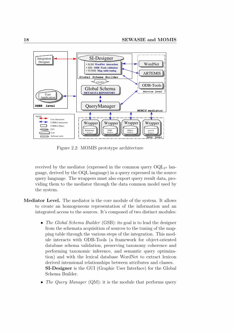
The MOMIS system is designed for schema integration. Figure 2.2 showsthe architecture of the system in terms of functional modules. The system iscomposed of several objects that communicate using the CORBA3 standardand it follows the I3architecture [11]. The modules are on three levels:
Data Level. Here there are the Wrappers. They are placed over eachsource and represent the interface modules between the mediator andthe local data sources. They carry out a double function: in the inte-gration phase, they translate the description of the information held inthe source. This description is supplied through the ODLI3 language;in the query processing phase, they translate the query which has been
3Object Management Group. http://www.omg.org/
18 SEWASIE and MOMIS
Wrapper Wrapper
Relational Source
Relational Source
Wrapper Wrapper
Relational Relational
Source
Wrapper Wrapper
XML Source
XML Source
Wrapper Wrapper
XML XML Source
Wrapper Wrapper
Object Source
Object Source
Wrapper Wrapper
Object Object Source
Wrapper Wrapper
generic Source
generic Source
Wrapper Wrapper
generic generic Source
legenda
CORBA Object
User
GUI
Software tools
CORBA interaction User interaction
legend
CORBA Object
User
GUI
Software tools
CORBA interaction User interaction
WordNet WordNet
Service level ODB - Tools ODB-Tools
Global Schema METADATA REPOSITORY
Global Schema METADATA REPOSITORY
Global Schema Builder
QueryManager QueryManager
• SLIM WordNet interaction • SIM ODB - Tools validation • ARTEMIS Clustering • TUNIM Map. table tuning
• SLIM WordNet interaction • SIM ODB - Tools validation • TUNIM Map. table tuning
SI-Designer
MOMIS mediator
creates
User User Application
Integration Designer
Integration Designer
USER level
User User Application
Integration Designer
Integration Designer
USER level
ARTEMIS
Data level
Figure 2.2: MOMIS prototype architecture
received by the mediator (expressed in the common query OQLI3 lan-guage, derived by the OQL language) in a query expressed in the sourcequery language. The wrappers must also export query result data, pro-viding them to the mediator through the data common model used bythe system.
Mediator Level. The mediator is the core module of the system. It allowsto create an homogeneous representation of the information and anintegrated access to the sources. It’s composed of two distinct modules:
• The Global Schema Builder (GSB): its goal is to lead the designerfrom the schemata acquisition of sources to the tuning of the map-ping table through the various steps of the integration. This mod-ule interacts with ODB-Tools (a framework for object-orienteddatabase schema validation, preserving taxonomy coherence andperforming taxonomic inference, and semantic query optimiza-tion) and with the lexical database WordNet to extract lexiconderived intensional relationships between attributes and classes.SI-Designer is the GUI (Graphic User Interface) for the GlobalSchema Builder.
• The Query Manager (QM): it is the module that performs query
2.2 MOMIS 19
processing and optimization. The QM generates OQLI3queries tobe sent to wrappers starting from each query posed by the user onthe Global Schema. It automatically generates the translation ofthe query into a corresponding set of sub-queries for the sourcesand synthesizes a unified global answer for the user.
User Level. The designer interacts with the Global Schema Builder andbuilds the integrated view of the sources. The users pose the querieson the Global Schema then the QM performs the queries on the localsources and presents the users with an unified answer.
The MOMIS project aims at integrating data from structured and semi-structured data sources. SI-Designer is a support tool for semi-automaticintegration of heterogeneous sources schema (relational, object, XML andsemistructured sources).
The MOMIS approach to perform Global Virtual View is articulated inthe following phases:
1. Generation of a Common Thesaurus.The Common Thesaurus is a set of terminological intensional and ex-tensional relationships, describing intra and inter-schema knowledgeabout classes and attributes of sources schemas. We express intra andinter-schema knowledge in form of terminological and extensional re-lationships (synonymy, hypernymy and relationship) between classesand/or attribute names. In this phase the WordNet database is usedto extract lexicon derived relationships.
2. Affinity analysis of classes.Relationships in the Common Thesaurus are used to evaluate the levelof affinity between classes intra and inter sources. The concept ofaffinity is introduced to formalize the kind of relationships that canoccur between classes from the integration point of view. The affinity oftwo classes is established by means of affinity coefficients based on classnames, class structures and relationships in the Common Thesaurus.
3. Clustering classes.Classes with affinity in different sources are grouped together in clus-ters using hierarchical clustering techniques. The goal is to identifythe classes that have to be integrated because describing the same orsemantically related information.
4. Generation of the mediated schema.Unification of affinity clusters leads to the construction of the predicted
20 SEWASIE and MOMIS
schema. A class is defined for each cluster, which is representative ofall clusters’ classes and is characterized by the union of their attributes.The global schema for the analyzed sources is composed of all classesderived from clusters, and is the basis for posing queries against thesources.
A graphical tool, the Source Integration Designer, SI-Designer, has beendeveloped to support the designer during the source integration phase. Moredetails about SI-Designer will be presented in section 4.1.

Chapter 3
Ontologies
Many articles in the literature have been devoted to presenting differentdefinitions and features of ontologies; in this chapter we have followed theoverview written by Valentina Tamma in her Ph.D. Final Thesis [12].
The need to share knowledge and information with other applicationsalready built, has given rise to a growing interest in research on ontology.This term has been originally used in Philosophy where it indicated the sys-tematic explanation of Existence. More recently, the term has been used invarious areas in Artificial Intelligence (AI) and more widely in Computer Sci-ence, such as knowledge engineering, knowledge representation, qualitativemodelling, database design, language engineering, information integration,information retrieval and extraction, knowledge management and organisa-tion, agent-based system design and e-commerce [13]. Ontologies play alsoa key role in one of the newest area of interest, the Semantic Web, as con-firmed by efforts such as OntoWeb (http://www.ontoweb.org) and DAML(http://www.daml.org).
3.1 Definitions
In each area mentioned before, the term “ontology” can take a different mean-ing. In some cases this term denotes a set of activities performed followinga standardised methodology, such as conceptual analysis and domain mod-elling, while in some other cases it just indicates a warehouse of vocabularyto solve lexical, semantic and synonym problems. It is thus clear that thereis no unique definition of the term “ontology”. The meaning of the termontology changes moving from philosophy to AI. The philosophical accountfor the term ontology is the branch of metaphysics that deals with the natureof Being, and it can be considered as a particular system of categories ac-

22 Ontologies
counting for a certain vision of the world [13]. In the remainder of the thesisthe word ontology is used as an uncountable noun (which does not have aplural form) when it refers to the philosophical notion of ontology, whereaswe will use it as a countable noun when referring to the engineering artifactsdefined in AI.
One of the most widely quoted definition of “ontology” was given by TomGruber in 1993, who states [2, p. 199]:
an ontology is an explicit specification of a conceptualization.
A useful link to find additional information ishttp://www-ksl.stanford.edu/kst/what-is-an-ontology.htmlmaintained by Gruber. According to Gruber an ontology is a quintuple com-posed of classes, instances, functions, relationships, axioms. Classes corre-spond to entities of the domain, instances are the actual objects which are inthe domain, functions and relationships relating entities of the domain, andfinally axioms constrain the meaning and the use of classes and instances,functions and relationships.
Another definition of ontology, often used in literature, has been given byNicola Guarino in [13]:
an ontology is a set of logical axioms designed to account for theintended meaning of a vocabulary.
From this definition arises the relationship between a conceptualization andthe ontology which specifies and formalize it.
Now I present a list of interesting definitions that other researcher groupshave studied. In fact, each research group involved in the ontological fieldhas tried to clarify their view on ontologies and have developed their owndefinition of ontology. These definitions depend on the purposes for whichthey have been developed, but, despite some minor differences, they refer tothe ontology as a common understanding of a domain, and that implies that itis a repository of vocabulary for the knowledge of a domain. The vocabularycontains both formal and informal definitions. Borst has extended Gruber’sdefinition [14, p. 12]:
an ontology is a formal specification of a shared conceptualization.
Studer and collegues have merged Gruber’s and Borst’s definition, andhave provided an explanation for the terms used [15, p. 185]:
An ontology is a formal, explicit specification of a shared concep-tualisation. A ’conceptualisation’ refers to an abstract model of

3.1 Definitions 23
some phenomenon in the world by having identified the relevantconcepts of that phenomenon. ’Explicit’ means that the type ofconcepts used, and the constraints on their use are explicitly de-fined. ... ’Formal’ refers to the fact that the ontology should bemachine-readable. ’Shared’ reflects the notion that an ontologycaptures consensual knowledge, that is it is not private to someindividual, but accepted by a group.
Neches and colleagues developed the following definition about what isdefined by an ontology [16, p. 40]:
An ontology defines the basic terms and relations comprising thevocabulary of a topic area, as well as the rules for combining termsand relations to define extensions to the vocabulary.
This definition states clearly that an ontology is not only describing theexplicit knowledge about a domain, but also the knowledge that can beinferred.The relationship between ontologies and knowledge bases has been includedin the definition of Bernaras and colleagues [17]; they have defined what aknowledge base provides while designing an ontology:
The ontology provides the means for describing explicitly the con-ceptualisation behind the knowledge represented in a knowledgebase.
Swartout and colleagues [18], on the other hand, have defined the contribu-tion given by an ontology to the design of a knowledge base:
An ontology is a hierarchically structured set of terms describinga domain that can be used as a skeletal foundation for a knowledgebase.
Each definition presented above highlights a specific aspect of the roleplayed by ontologies. All definitions share the idea that an ontology providesa description of a particular viewpoint about a domain and that such adescription must be explicit, because it states a vocabulary for the domain,which is expressed by a certain degree of formality, and that a group commitsto use the vocabulary according to the intended meaning associated with itin order to communicate.

24 Ontologies
Ontologies, then, can be classified into lightweight and heavyweight on-tologies, depending on the degree of formality used to express them. Heavy-weight ontologies are those which are provided with axioms, inference mecha-nisms aimed to equip ontologies with deductive power (e.g., inheritance), andthat are characterised by a high degree of formality (e.g., underlying formalsemantics). Lightweight ontologies, on the other hand, are those ontologiesthat define a vocabulary of terms with some specifications of their meaning[19].
3.2 Modelling primitives
Before proceeding by illustrating the different types of ontologies we intro-duce here the conceptual primitives that can be used when knowledge abouta domain is formalised in an ontology. In [2] an ontology is defined as thequintuple:
(C, I,R,F ,A)
where:
• C is the set of the concepts, that is the set of the abstractions used todescribe the objects of the world;
• I is the set of individuals, that is, the actual objects of the world. Theindividuals are also called instances of the concepts;
• R is the set of relationships defined on the set C, that is, each R ∈ R isan ordered n-ple R= (C1×C2× . . .×Cn). For example subconcept-ofis the pair (Cp,Cc) where Cp is the parent concept and Cc is the childconcept;
• F is the set of functions defined on the set of concepts and that returna concept. That is, each element F is a function F: (C1 × C2 × . . . ×Cn−1 7→ Cn). For example, the function Price-of-flat is functionof the concepts Year, Location and Number-of-square-metres, andreturns a concept Price, that is Price-of-flat: Year × Location ×Number-of-square-metres 7→ Price;
• A: set of axioms, that is first order logic predicates that constrain themeaning of concepts, relationships and functions.

3.3 Ontologies classification 25
Some of these components have necessarily to be in an ontology. For ex-ample, few ontologies include also instances. The simplest type of ontologyis composed by the set of concepts C and the relationships R (lightweightontologies), although this limits the knowledge that can be expressed about adomain. Concepts are also called classes. Concepts and instances are usuallyorganised in an Is-a hierarchy, which permits, when it is a strict relationship(in the mathematical sense), inheritance to be exploited in the structure,that is if A is an ancestor of B (denoted by A 7→ B) and B 7→ C then, A 7→C. When ontologies include also the content concerning ground individualsand their relationships with the concepts they instantiate, then the notionof inheritance is extended to instances and it is called the instance relation.The Is-a relationship, also called the subclass relationship, is not the onlyone that can be defined on concepts.
Concepts can be defined in terms of characteristic features describingthem, that are called attributes. If the concepts are organised in an Is-ahierarchy, then the inheritance is extended also to attributes. Attributes areshared by concepts either in their original form or modified in order to givethe inheriting class, known also as subclass, a more restrictive definition thanthe one provided by the parent concept. Furthermore other properties canbe added to form more specialised concepts.
3.3 Ontologies classification
The ontologies presented in the literature can be classified according to dif-ferent dimensions, which range from the level of generality of the conceptsthey describe, to the type of knowledge they model. In this section I presentthe most commonly used classifications of ontologies. The first dimensionthat can be used to classify ontology is the level of generality that is used inthe description of a domain. It is possible to distinguish the following typesof ontologies [13]:
• Top-level ontologies : this kind of ontology describes very general con-cepts or common-sense knowledge such as space, time, matter, object,event, action, etc., which are independent of a particular problem ordomain.
• Domain ontologies : this kind of ontology describes the vocabulary re-lated to a generic domain such as medicine or physics.
• Task ontologies : this kind of ontology describes the vocabulary relatedto a generic task or activity such as diagnosis or selling.

26 Ontologies
• Application ontologies : this kind of ontology describes concepts de-pending both on a particular domain and on a particular task. Theyare often a specialisation of both domain and task ontologies and corre-spond to the roles played by domain entities when they perform certainactivities.
Van Heijst and colleagues propose to classify ontologies according to twodimensions, which are the amount and the type of structure of the concep-tualisation and the subject of the conceptualisation [20].
• Amount and type of structure of the conceptualisation: this dimensionis mainly concerned with the level of granularity of the conceptualisa-tion and thus can be subdivided into:
- Terminological Ontologies: these are not strictly speaking ontologiesbut just lexicons that specify the terminology that is used to repre-sent knowledge in the domain of discourse. They do not representthe semantics of the terms;
- Information Ontologies: they specify the record structure of databases(for example, database schemata). They provide means to recordthe basic observations concerning instances of the database, butthey do not define the concepts that are instantiated by theseinstances;
- Knowledge Modelling Ontologies: they specify conceptualisations ofknowledge. They are structurally richer than information ontolo-gies and are often specified according to a particular use of theknowledge they describe.
• Subject of the conceptualisation: this dimension concerns the type ofknowledge that is modelled in the ontologies. Four categories are dis-tinguished along this dimension:
- Application Ontologies: specify those concepts that are necessary inorder to model the knowledge required for a specific applications.Usually, application ontologies specialise terms taken from moregeneral ontologies such as the domain and the generic ontologiesdescribed below and may extend generic and domain knowledgeby representing method and task-specific components. Applica-tion ontologies are not reusable, they reuse knowledge which maybe modelled in ontology libraries by tuning it for the specific ap-plication at hand;

3.3 Ontologies classification 27
- Domain Ontologies: specify those concepts that are specific of a par-ticular domain. Knowledge engineers draw a line between domainontologies and domain knowledge, where the former has ontologi-cal nature and the latter epistemic. Domain knowledge describesfactual situations in certain domains whereas domain ontologiesspecify the constraints to apply on the structure and the contentof the domain knowledge. But the distinction between what is on-tological and what is epistemological is quite subtle, and thereforesuch a line often cannot be drawn too neatly.
- Generic Ontologies: specify concepts that are generic across manyfields. Concepts in the domain ontologies may specialise thosein the generic ontologies in order to tune them to a particulardomain. Generic ontologies correspond to the top-level ontologiesin Guarino’s classification presented above; they typically defineconcepts like state, event, process, action, etc.
- Representation Ontologies: explicate conceptualisations underlyingknowledge representation formalisms. They provide a representa-tional framework without making claims about the world, becausethey are meant to be neutral with respect to the world. Domainand generic ontologies are described by means of the primitivesgiven in the representation ontologies.
Ontologies differ also in the degree of formality by which the terms andtheir meaning are expressed in the ontology, as in [21]. Here, the knowledgeexpressed in the ontology might be the same, but they differ in the way inwhich it is expressed.In discussing how formally ontologies are described, it makes little sense totalk about categories, because the degree of formality is better thought of asa continuum rather than a set of classes.Nevertheless, we can set four points in this continuum:
• Highly informal: are those ontologies expressed in natural language.Term definitions might be ambiguous due to the inherent ambiguity ofnatural language;
• Semi-informal: these ontologies are expressed in a restricted and struc-tured form of natural language. Restricting and structuring naturallanguage achieves improvement in clarity and reduction in ambiguity;
• Semi-formal: these are ontologies expressed in artificial languages whichare formally defined, such as Ontolingua [22];

28 Ontologies
• Rigorously formal: these are ontologies whose terms are precisely de-fined with formal semantics, theorems and proofs of desired propertiessuch as soundness and completeness.
Along the same line, McGuinness in [23] “classifies” ontologies on the groundof their expressiveness, that is, on the grounds of the information that theontology needs to express. In fact, depending on the different types of in-terpretation which are associated with the word ontology, we can distinguishbetween less or more complex notions of ontologies, which may range from acontrolled vocabulary, to a glossary, to reach, at the other end of this spec-trum, ontologies which also provide general logical constraints such as dis-jointness, inverse, part of, etc. The points they distinguish in the spectrumare:
• Controlled vocabularies: a vocabulary is the simplest possible notion ofontology, that is a finite list of terms. A typical example of this categoryis catalogues. Indeed, catalogues provide terms with an unambiguousinterpretation, but nothing more;
• Glossaries: they are a list of terms and their meanings. The meaningsare usually expressed in natural language statements that are chieflyaimed at humans. These statements, however, are ambiguous and can-not be used by computer agents;
• Thesauri: add to glossaries the semantics emerging from the definitionof the relations between terms, such as the synonym relationship. Typ-ically, they do not provide an explicit hierarchical structure, althoughthis can often be deduced by broader or narrower term specifications.A computer agent can often interpret the relationships defined in athesaurus univocally;
• Informal Is-a hierarchies: this category includes many of the ontologieson the web. These are ontologies where a general notion of generali-sation and specialisation is provided although it is not strict subclasshierarchy. A typical example is Yahoo! , which provides a small num-ber of top-level categories, but does not provide an explicit hierarchicalstructure, and its hierarchy is not a strict subclass of the Is-a hierar-chy. In hierarchies that are not strict Is-a hierarchies it is not alwaysthe case that an instance of a more specific class is necessarily an in-stance of a more general class, therefore inheritance (with or withoutexceptions) cannot be assumed here;

3.3 Ontologies classification 29
• Formal Is-a hierarchies: these are ontologies where concepts are organ-ised according to a strict subclass hierarchy. Thus, for these ontologiesinheritance is always applicable because it is always the case that ifa concept C is a superclass of the concept C ′, then any subclass of C
must necessarily be a subclass of C ′. These ontologies may include onlyclass names;
• Formal instances: ontologies including formal instance relations are anatural extension of ontologies enforcing a strict hierarchical structure.Indeed, some classification schemes include only class names, as wehave pointed out when discussing strict subclass hierarchies. Whenformal instance relations hold, the ontologies include also the contentconcerning ground individuals and their relationships with the conceptsthey instantiate;
• Frames (description of concept properties): these are ontologies whoseconcepts are described in terms of their characteristic properties. Forexample, a concept Book might be described in terms of features liketitle, author, publisher, etc. The inclusion of properties in the conceptdescription becomes more interesting when inheritance can be appliedto these properties, and thus properties can be specified for a moregeneral concept and be inherited down the hierarchy by more specificconcepts;
• Value restriction: these ontologies permit to apply restrictions on thevalues associated with properties. For example, in describing the con-cept Book we might restrict the value to associate with the propertyAuthor to be composed of maximum two names. These restrictions areusually to be inherited by the sub-concepts of the concept where theyare stated for the first time, which clearly poses a problem when thetype of hierarchical relation supported by the ontology is not a strictsubclass relation;
• General logical constraints: these ontologies are those with the richestexpressiveness. For example, properties might be based on mathemat-ical equations, which use values from other properties, or propertiesmight be expressed as logical statements. This type of ontology is usu-ally written in very expressive ontology languages, such as Ontolingua[22], which permit the specification of first order logic constraints onconcepts and their properties.
As a final consideration, it may be important to make clear the differ-ence between an application ontology and a knowledge base. The answer

30 Ontologies
is related to the purpose of an ontology, which is a particular knowledgebase, describing facts assumed to be always true by a community of users,in virtue of the agreed-upon meaning of the vocabulary used. A genericknowledge base, instead, may also describe facts and assertions related to aparticular state of affairs or a particular epistemic state. Within a genericknowledge base, we can distinguish therefore two components: the ontology(containing state-independent information) and the “core” knowledge base(containing state-dependent information).
3.4 Ontology dynamics – different approaches
With rising importance of knowledge interchange, many industrial and aca-demic applications have adopted ontologies as their conceptual backbone.However, business dynamics and changes in the operating environment oftengive rise to continuous changes to application requirements that may be ful-filled only by changing the underlying ontologies. This is especially true forWWW and Semantic Web applications, that are based on heterogeneous andhighly distributed information resources and therefore need efficient mecha-nisms to cope with changes in the environment. So over a period of time anontology needs to be modified to reflect changes in the real world, changes inuser’s requirements, drawbacks in the initial design, to incorporate additionalfunctionality or to allow for incremental improvement. In fact very seldoman ontology is perfect the first time it is made, and then continues, withoutchange, to be as useful over time as when it was first deployed. The reasonsfor changes are inherent in the complexity of reality and in the limited abilityof humans to cope with this complexity. Thus a small list of possible causesof change may be the following:
• Ontologies often contain “design error” and sometimes do not immedi-ately meet the requirements of its users;
• The environment in which the ontology operates can change unpre-dictably, thereby invalidating the assumptions that were made whenthe ontology was built;
• Users’ requirements can change after the ontology is initially built,requiring that the existing ontology evolves to meet the new require-ments.
Another way to comprehend the causes of change is to refer to the Gruberdefinition of ontology [2] (it is a specification of a shared conceptualization ofa domain). Analyzing this definition we can enlighten these causes of change:

3.4 Ontology dynamics – different approaches 31
1. changes in the domain;
2. changes in the shared conceptualization;
3. changes in the specification.
The first type of change is often occurring and is well known in thedatabase schema versioning area. In this case changes in the domain re-quire changes in the database model. An example of this type of change isthe merge of two university departments. As the ontology describes the realworld, a change in it requires a modification in the ontology itself.
About the second case, it is important to notice that the shared concep-tualization of a domain is not a static specification produced only once inthe history, but has to be reached over time. Fensel [24] describes ontologiesas dynamic networks of meaning, in which consensus is achieved in a socialprocess of exchanging information and meaning. This view gives a dual roleto ontologies in information exchange; they provide consensus that is both apre-requisite for information exchange and a result of this exchange process.Often the conceptualization can change because of the usage perspective. Infact different tasks may need different views on the domain and consequentlya different conceptualization. For example when an ontology is adapted fora new task or domain, the modifications represent changes to the conceptu-alization. When an ontology about a traffic connections with concepts likeroads, bridges, is adapted for a bicycle perspective new concepts have to beadded and other have to be modified or removed.
Eventually the specification change is a kind of translation, i.e. a changein the way in which a conceptualization is formally recorded. Therefore thistype of change is less interesting because it has a simple solution. In facttranslation should retain the semantics, as the specification variants shouldbe equivalent and they only cause syntactic change.
At the end of this overview of the causes of changes, it is simple to under-stand the fundamental necessity to have methods, tools, framework, environ-ment to face the dynamics aspect of ontologies. Many research groups areinvolved in the solving of this crucial issue. In the following two approachesare presented.
The first is the Evolution approach. It is proposed by [25] and [26] andit is developed at the University of Karlsruhe (Germany). This approachintend to face the dynamics problem in all its complexity and to manage allthe consequences that changes require.
The second is the Versioning approach. It is proposed by [24] and it isdeveloped at the Free University of Amsterdam (The Netherlands). This

32 Ontologies
approach, differently from the previous one, try to cope with the complexityof the problem suggesting a system based on versions (or better, on ontologyversions).
3.4.1 Evolution approach
The ontology evolution [24] is the timely adaptation of the ontology as wellas the consistent propagation of changes, because a modification in one partof the ontology may generate subtle inconsistencies in other parts of the sameontology, in the instances, depending ontologies and applications. The on-tology evolution is becoming more important nowadays. The major reasonfor this is the increasing number of ontologies in use and the increasing costsassociated with adapting them to changing requirements. Developing on-tologies and their applications is expensive, but evolving them is even moreexpensive. However, even though evolution over time is an essential require-ment for useful ontologies, appropriate tools and strategies for enabling andmanaging evolution are still missing. This level of ontology management isnecessary not only for the initial development and maintenance of ontologies,but it is essential during deployment, when scalability, availability, reliabilityand performance are absolutely critical.
Ontology development is now clear, it is a dynamic process starting withan initial rough ontology, which is later revised, refined and filled in thedetails [27]. Consequently, an ontology almost certainly should be evolved inorder:
• to fix “bugs” in the initial design (corrective maintenance);
• to adapt itself to the changes in the environment (adaptative mainte-nance);
• to improve itself after it has become operational (perfective mainte-nance);
• to avoid future changes and to alleviate maintenance (preventive main-tenance).
Moreover, ontology evolution has to be supported through the entire lifecycle[28].
The most important problem to face when a change to an ontology oc-curs, is to ensure the consistency of the ontology and all the dependentartifacts. When a change to a consistent ontology is identified, we have tounderstand how to carry out it in order to maintain its consistent state. The

3.4 Ontology dynamics – different approaches 33
importance of this problem became more clear if we consider the instancesthat rely on the ontology and all the applications that depend on it. Thisissue can be faced diving it in four phases as shown in Figure 3.1.
Change Representation
Semantics of Change
Change Implementation
Change Propagation
Request for the change
Required change
Required and
derived changes
Modified ontology and local instances
Suggestion for the changes: - distributed instances - dependent ontologies - dependent applications
Source Ontology
Ontology Instances
Dependent ontologies
Applications
Figure 3.1: Four elementary phases of ontology evolution process
Change Representation
Approaching this problem, the first thing to do is trying to represent thechanges, that means to identify and to represent them in the correct format.In the course of ontology evolution different type of changes can be requested.Some of them are simple and interest a defined component of the ontology.Sometimes the changes are complex and involve several components of theontology, in addition the intent of these changes can be expressed on a higherlevel. For example, they may need to generate a common superconcept sc oftwo concepts c1 and c2. To take the ontology into the desired state, a list ofchanges have to be applied:
- Add Concept sc;
- Delete SubConceptOf relation from c1 to its current parent;
- Add SubConceptOf relation from c1 to sc;
- Delete SubConceptOf relation from c2 to its current parent;
- Add SubConceptOf relation from c2 to sc.
This case presents significant drawbacks: (I) five steps are needed toperform the intent change, the process is error prone; (II) a lot of unnecessarychanges may be performed if each change is applied alone. For example,removing sub-concept-of relation from c1 may introduce changes to propertyinstantiations that should be reversed when assign sub-concept-of relation

34 Ontologies
from c1 to sc.To avoid these drawbacks, changes should be express on a more coarse level,with the intent of change directly visible. In this way it become simpler tounderstand the meaning and the objective of the requested changes. Someexample of composite changes are presented in the table 3.1.
Composite change DescriptionMerge concepts Replace several concepts with one and aggregate all instances.Extract subconcepts Split a concept into a several subconcepts and distribute
properties among them.Extract superconcepts Create a common superconcepts for a set of unrelated
concepts and transfer common properties to it.Pull up properties Move properties from a subconcept to superconcept.Move properties Move properties from one concept to another concept.Move instance Moves an instances from one concept to another.
Table 3.1: Composite changes in the ontology
Semantics of Change
Application of an elementary change in the ontology can induce inconsisten-cies in other parts of the ontology. We can distinguish syntax and semanticinconsistency. Syntax inconsistency arises when undefined entities at theontology or instance level are used or ontology model constraints are in-validated. Semantic inconsistency arises when the meaning of an entity ischanged due to changes performed in the ontology.For example, removal of a concept which is the only element of domain setfor some property results in syntax inconsistency. Resolving that problemis treated as a request for a new change in the ontology, which can inducenew problems that cause new changes and so on. Therefore, one changecan potentially trigger other changes and cause an unpredictable chain ofalterations. If an ontology is large, it may be difficult to fully comprehendthe extent and the meaning of each induced change. The task of ‘semanticsof change’ phase is to enable resolution of induced changes in a systematicmanner, ensuring consistency of the whole ontology. To help in better under-standing the effects of each change, this phase should contribute maximumtransparency providing detailed insight into each change being performed.
In the course of evolution, actual meanings of concepts often shifts to bet-ter represent the structure of the real world. While some shifts of conceptmeaning are performed explicitly, a meaning of a concept can sometimesshift implicitly through changes in other parts of the ontology. For example,

3.4 Ontology dynamics – different approaches 35
consider an ontology describing a relationship between jaguars and persons.In this ontology the meaning of the concept Jaguar is clear through the ex-istence of the property eats that links Jaguars and Persons – it is clear thatconcept Jaguar stands for an animal. For any reason one may delete the con-cept Person, which may result in the removal of the property eats as well.After this change, the semantics of concept Jaguar is not clear any more –is it a Jaguar cat or a Jaguar car? This example highlights the importanceof the semantics of change and the problems that arise if we do not treat itproperly. For this reason is important to use a rich description of each ontol-ogy entity. One way may be attaching meta-information about e.g. essentialproperties of a concept.
Change Implementation
This phase has the principal aim to prevent undesired changes. Before ap-plying a change to the ontology, a list of all implications to the ontologyis generated and presented to the user. He should be able to comprehendthe list and approve or cancel the change. When the changes are approved,they are performed by successively resolving changes from the list. At thisstage, no action is already done, in fact if changes are cancelled, the ontologyremains intact.
Change Propagation
When the ontology is modified, ontology instances need to be changed topreserve consistency with the ontology. This can be performed in three steps.In the first step, the instances are collected in the knowledge base (often theyare widespread on the Web). In the second step, modification of instances isperformed according to the changes list prepared in the previous phases. Inthe last step “out-of-date” instances are replaced with corresponding “up-to-date” instances.Despite this simple process the change propagation arises some importantproblems. As ontologies often reuse and extend other ontologies, an ontologyupdate might also corrupt ontologies that depend on the modified ontologyand also all artifacts that are based on these ontologies. One possible solutionto this problem is the recursive application of the ontology evolution processon all the interested ontologies. Nowadays many applications are based onontologies so when an ontology is modified the application may not workcorrectly. The ontology evolution system has to recognize which change inthe ontology can affect the functionality of the dependent applications andreact with the right operations.

36 Ontologies
Eventually, to explain the complexity of the ontology evolution processFigure 3.2 can be useful. It shows how the process has a cyclic structure,
6. Validation
Businness requirements
Discovering
1. Capturing
2. Representation
3. Semantics of change
4. Implementation
5. Propagation
Figure 3.2: Ontology Evolution Process
since validation of realized changes may (automatically) induce new changesin order to obtain a consistent state or to satisfy users’ expectations. Thephases 2 to 5 correspond to the evolution process explained before; phase6 gives the user the opportunity to control the process and to supervise it,while phase number 1 is fundamental to continuously identify changes topropose to the user for preventing changes or improving the quality of theontology.
3.4.2 Versioning approach
In the previous section we have seen one of the most interesting approach tothe dynamics of ontologies, but it is not the only one. In literature severalstudies start assuming that the complexity of the dynamics involving ontolo-gies, applications and instances, is too high to maintain everything aligned.As we have already seen, a request for changing an ontology can start a longprocess to keep consistent the ontology and all the entities that depend onit. A versioning methodology can handle this complexity providing the userwith such a system that manages ontology revisions over time.Before going deeper in this argument it is better to explain what actually

3.4 Ontology dynamics – different approaches 37
means versioning. In a general sense, ontology versioning means that thereare multiple variants of an ontology around. In practice, those variants oftenoriginate from changes to an existing variant of the ontology and thus forma derivation tree. It is also possible that different “versions” of ontologies ofthe same domain are independently developed and do not have a derivationrelation. In this case, however, we will not use the word “version”, but wewill see the variants as separate ontologies that describe the domain from aspecific viewpoint or perspective. In this view, ontology versioning is closelyrelated to changes in ontologies [24].
Ontology versioning can be defined as the ability to handle changesin ontologies by creating and managing different variants of it. In order toachieve this ability a methodology has been studied. In particular methodsto distinguish and recognize versions, and procedures to update and changeontologies are provided.
Analysis of compatibility
The consequences of the change are very important, as we have already saidbefore (see section 3.4.1). Now we discuss the problems that a versioningsystem has to solve related to the compatibility of changed ontologies anddata sources.A typical scenario presents various versions of many ontologies around. A lotof web pages or applications use (or are intended to use) a specific versionof the ontology. At this point incompatibility problems arise. In fact it isnot clear which version of an ontology is related to a certain data source.Basically there are tree ways to relate ontology versions with data sources:1) using the intended version of the ontology; 2) using a newer version of theontology; 3) using an older version of the ontology. The first type of com-bination is clearly compatible, so we focus our attention on two directions,which are illustrated in figure 3.3. The terms used in the following are wellknown in the schema versioning literature; they describe the two directionsof investigation.
• Prospective use: the use of data sources that conform to a previousversion of the ontology via a newer version of the ontology (i.e. viewthe data from a newer perspective).
• Retrospective use: the use of data sources that conform to a newerversion of the ontology via a previous version of the ontology (i.e. viewthe data from an older perspective).

38 Ontologies
Ontology version 1
Datasource
Conform to
Ontology version 2
Datasource
Conform to
Ontology version 3
Datasource
Conform to
Prospective use
Ontology version 1
Datasource
Conform to
Ontology version 2
Datasource
Conform to
Ontology version 3
Datasource
Conform to
Retrospective use
Figure 3.3: Two examples of prospective and retrospective use of ontologies
Based on these directions of use we can now categorize the compatibilityrevisions into different types. In this categorization, we examine whether itis valid to use a revision of an ontology on the set of all possible instances ofan other revision of the ontology. In other words, we assume that the datasources that conforms to a specific version of the ontology uses the wholeontology, i.e., all concepts and relations. This is the worst scenario. Table3.2 shows the types of compatibility.
prospective use validyes no
retrospective yes full compatible upward compatibleuse valid no backward compatible incompatible
Table 3.2: Categorization of compatibility
The types of revisions can be described as follow:
• full compatible revisions (upward and backward): the semanticsof the ontology is not changed, e.g. syntactic changes or updates ofnatural language descriptions; this type of change is compatible in bothprospective use and retrospective use;
• backward compatible revisions: the semantics of the ontology ischanged in such a way that the interpretation of data via the new ontol-ogy is the same as when using the previous version of the ontology, e.g.the addition of an independent class; this type of change is compatiblein prospective use;
• upward compatible revisions: the semantics of the ontology ischanged in such a way that an older version can be used to interpretnewer data sources correctly, e.g. the removal of an independent class;this revision is compatible in retrospective use;

3.4 Ontology dynamics – different approaches 39
• incompatible revisions: the semantics of the ontology is changed insuch a way that the interpretation of old data sources is invalid, e.g.changing the place in the hierarchy of a class; this type of change isincompatible in both prospective use and retrospective use.
Note that both backward compatibility and upward compatibility are tran-sitive: when the changes from v1 to v2 as well as the changes from v2 to v3are backward compatible, then the changes from v1 to v3 are also backwardcompatible. So, if all subsequent revisions to an ontology up to a certainversion are backward compatible, it is also possible to name the resultingversion of the ontology itself backward compatible. However, it is never al-lowed to call a version of an ontology upward or full compatible, because thesemantics of future versions are not known beforehand. It is always possiblethat new versions of ontologies will introduce new things that cannot cor-rectly be interpreted via older versions. Thus, backward compatibility can bea characteristic of an ontology, but upward or full compatibility can not.
Requirements for versioning framework
As we have seen there are various scenarios for ontology changing. Now wepresents some requirements and goals for a versioning system.Principally a versioning methodology should provide mechanisms and tech-niques to manage changes to ontologies, while achieving maximal interoper-ability with existing data and applications. This means that it should retainsas much information and knowledge as possible, without deriving incorrectinformation. This general achievement can be translate in a more detailedlist of requirements:
- for every use of a concept or a relation, a versioning framework shouldprovide an unambiguous reference to the intended definition (identification);
- a versioning framework should make the relation of one version of aconcept or relation to other versions of that construct explicit (changespecification);
- a versioning framework should – as far as possible – automaticallytranslate and relate the versions and data sources, to enable transparentaccess (transparent evolution).
Fensel et al. [24] are working on this framework and till now they havestudied in particular the identification and change specification problems.

40 Ontologies
Identification
In order to manage various versions of ontologies is fundamental to iden-tify each version unequivocally. About this issue there are different opinionson how to treat changes. In fact one can see an ontology as a specifica-tion of a conceptualization, so every modification to the specification can beconsidered a new conceptualization of the domain. In that case, the descrip-tions specify different concepts, which are per definition not equal. Anotherperspective can see an ontology primarily as a conceptualization, which isrepresented as complete as possible in a specification. In this case one couldargue that an update to a natural language description of a concept is nota semantic change, but just a refined description of the same conceptualiza-tion. To solve this debate an ontology is represented as a file on the Web.Every change that results in a different character representation of an on-tology constitutes a revision. When the logical definitions are not changed,the author of the revision has to decide whether the revision is a semanticchange and thus forms a new conceptualization with its own identity, or justa change in the representation of the same conceptualization.The concrete translation of this debate is that an ontology is considered asa resource on the Web, thus it can be identified with a URI (Uniform Re-source Identifier). Fensel et al. in this way propose to separate the identityof ontologies completely from the identity of files on the web that specifiesthe ontology. In other words, the class of ontology resources should be dis-tinguished from the class of file resources. A revision – normally specified ina new file – may constitute a new ontology, but this is not automatic. Everyrevision is a new file resources and gets a new file identifier, but does notautomatically get a new ontology identifier.The method can be summarized with the following points:
• a distinction between three classes of resources:
1. files;
2. ontologies;
3. lines of backward compatible ontologies.
• a change in a file results in a new file identifier;
• the use of a URL for the file identification;
• only a change in the conceptualization results in a new ontology iden-tifier;
3.4 Ontology dynamics – different approaches 41
• a new type of URI for ontology identification with a two level numberingscheme:
- minor numbers for backward compatible modifications (an ontology-URI ending with a minor number identifies a specific ontology);
- major numbers for incompatible changes (an ontology-URI end-ing with a major number identifies a line of backward compatibleontologies);
• individual concepts or relations, whose identifier only differs in minornumber, are assumed to be equivalent;
• ontologies are referred to by an ontology URI with the according majorrevision number and the minimal extra commitment, i.e., the lowestnecessary minor revision number.
Change specification and transparent evolution
For change specification and transparent evolution, there are two importantrequirements.First, in consequences of the suggested practice of referring to the minimalextra addition, the changes in a line of backward compatible ontologies shouldbe easily recognizable and identifiable. A proposal in this direction is to adda class Addition<Major>.<Minor>, e.g., Addition1.2, of which the new de-scriptions are an instance. This makes that class a unique identifier for theset of additions in a certain revision. Then, the additions can be retrievedby asking for all instances of a specific “Addition” class.Second, the relation to a previous version should explicitly be specified. Oneaspect of this specification is a pointer to the ontology from which it is de-rived. These pointers form a lattice of versions that can be used to deducethe derivation relation from one version to an arbitrary other version of theontology. A second aspect of this specification is the relation between con-cepts and relations in the previous and current version of the ontology. Asconcepts and relations that do not have the same major number in theiridentifier are assumed to be different, this specification should both specifyequivalence relations as subsumption relations.


Chapter 4
Ontology management – toolsand projects
Ontology management is a crucial problem within the Semantic Web. As wehave already seen before, ontology evolves at a high frequency rate, so theontology management is a key challenge to exploit the enormous possibilitiesof the Semantic Web.
We start by describing SI-Designer, the GUI of the MOMIS project thatsupports the designer during the source integration phase. We insert itsdescription here because it can be seen as an ontology management tool. Infact, beside its fundamental role during the integration process, it is also usedto construct the MOMIS ontology (see sec. 4.1.3).
Secondly we will explain the requirements that an ontology editor shouldhave to be able to handle ontologies during all their life cycle. Doing thiswe will better understand the problems related to changes and the possiblesolution to keep the ontology consistent.
Afterwards we will present an overview of the existing tools and projectsthat aim at helping the user during the ontologies’ development and integra-tion process.
4.1 Sources integration with SI-Designer
SI-Designer (Source Integrator Designer) is a designer support toolfor semi-automatic integration of heterogeneous sources schemata (relational,object and semi-structured sources). It has been implemented within theMOMIS project and it carries out integration following a semantic approachwhich uses intelligent Description Logics-based techniques, clustering tech-niques and an extended ODMG-ODL language, ODLI3 , to represent schemata

44 Ontology management – tools and projects
extracted information. Starting from the sources ODLI3 descriptions (localschemata), SI-Designer supports the designer in the creation of an integratedview of all the sources (global schema) which is expressed in the same ODLI3
language.
As described in section 2.2, the integration process is composed of varioussteps implemented in separate module. All the modules involved are availableas CORBAObject and interact using established idl interfaces. In particularthe SI-Designer provides (Fig 4.1) the designer with a graphical interfaceto interact with MOMIS modules showing the extracted relationships andhelping him in the Common Thesaurus construction. Once the CommonThesaurus has been built, SI-Designer uses the ARTEMIS [29] module toevaluate a disjoint set of structural similar classes (clusters). Each clusterhas a corresponding global class (a view over all similar classes belonging tothe cluster) characterized by a set of global attributes and a mapping-table.SI-Designer automatically generates a set of global attributes for each globalclass and a mapping table which maps each global attribute into the localattributes of the classes in the cluster.Then, a semi-automatic interaction with the designer starts: he may revisethe set of global attributes and the mapping table, to assign a name to eachglobal class, so as to achieve a global schema.
Local Schemata Acquisition
Intensional intra/inter schema relationships
extraction
Acquisition of relations provided by
designer
Inferred and validated relationships
Cluster Generation Global Class & Mapping-table
generation
DESIGNER
ARTEMIS
Common Thesaurus
Local Schemata
ODB-Tools
SIM
SLIM
Wrapper
Wrapper
Figure 4.1: SI-Designer Architecture.

4.1 Sources integration with SI-Designer 45
The integration process can be divided into two phases:
1. Generation of the Common Thesaurus;
2. Generation of the Global Schema.
At the end of the integration process the Global Virtual View generatedcan be exported into a XML DTD, by adding the appropriate XML TAGs torepresent the mapping table relationships. The use of XML in the definitionof the Global Virtual View makes it possible to use MOMIS infrastructurewith other open integration information system by the interchange of XMLdata files. In addition, also the Common Thesaurus is translated into anXML file, so that MOMIS may provides a shared ontology that can be usedby different semantic ontology languages.
4.1.1 Generation of the Common Thesaurus
The Common Thesaurus is a set of terminological intensional and ex-tensional relationships, describing intra and inter-schema knowledge aboutclasses and attributes of sources schemas ; it provides a reference to definethe identification of classes candidate to integration and subsequent deriva-tion of their global representation. In the Common Thesaurus, we expressknowledge in form of intensional relationships (SYN, BT, NT, and RT) andextensional relationships (SYNext, BText, and NText) between classes and/orattribute names. The Common Thesaurus is constructed through an incre-mental process during which relationships are added in the following order:
1. Schema-derived relationships.Intensional and extensional relationships holding at intra-schema level.These relationships are extracted analyzing each ODLI3 schema sepa-rately. In particular, intra-schema RT relationships are extracted fromthe specification of foreign keys in relational source schemas or complexattributes (relationships) in object oriented database. When a foreignkey is also a primary key both in the original and in the referencedrelation, a BT/NT relationship is extracted.
2. Lexical-derived relationships.Terminological relationships holding at inter-schema level are extractedby the SLIM module by analyzing different sources ODLI3 schemastogether according to the Wordnet supplied ontology.
3. Designer-supplied relationships.Intensional and extensional relationships supplied directly by the de-signer, to capture specific domain knowledge about the source schemata.

46 Ontology management – tools and projects
This is a crucial operation, because the new relationships are forcedto belong to the Common Thesaurus and thus used to generate theglobal integrated schema. This means that, if a nonsense or wrong re-lationship is inserted, the subsequent integration process can produce awrong global schema. Our system helps the designer in detecting wrongrelationships by performing a Relationships validation step with ODB-Tools. Validation is based on the compatibility of domains associatedwith attributes. For a complete description see [6].
4. Inferred relationships.Intensional and extensional new relationships, holding at intra-schemalevel, inferred by exploiting inference capabilities of ODB-Tools.
All these relationships are added to the Common Thesaurus and thusconsidered in the subsequent phase of construction of Global Schema.Relationships defined in each step hold at the intensional level by definition.Furthermore, in each of the above steps the designer may “strengthen” aterminological relationships SYN, BT and NT between two classes C1 andC2, by establishing that they hold also at the extensional level, thus definingalso an extensional relationship.
The WordNet lexical system
We use WordNet [9] lexical system as lexicon reference ontology ; this choice isdue most to these reasons: WordNet is a well-known and widespread lexicaldatabase, it seems to be a complete and professional instrument, is men-tioned in many scientific papers and it is continuously reviewed (for moredetails see [6]).Having different sources, it is however necessary to translate all their at-tributes and classes’ names in a common language, thus resulting in a map-ping process of all those terms in a well defined set of concepts (assumedas the WordNet ontology). This mapping process is often referred to inliterature as the sources annotation phase.
Sources annotation phaseWhat exactly the designer is requested for annotating the schema is to manu-ally choose a WordNet’s meaning for each schema element. Starting from theschema to be integrated, the designer must declare a relation between eachterm (class or attribute name) and the WordNet meaning appropriated forthe particular context. Then the designer must choose one or more meaningsfor each name. This is a two-step process.

4.1 Sources integration with SI-Designer 47
Word form choice In this step, the WordNet morphologic processor shouldaid the designer. A word form is the word without any suffixes due todeclination or conjugation. If such word form is not found or there isambiguity (E.g. axes has 3 word forms: ax (1 sense), axis (5 senses),axe (2 senses)), or it is not satisfactory, the designer can set a customword form. Notice that this operation, however, does not allow thedesigner to physically extend WordNet ontology with his particularannotation concept.About this issue a recent study to extend WordNet has been conductedby V. Guidetti in her thesis [30].
Meaning choice The designer can choose to map an element on zero, oneor more senses. For example WordNet has 15 meanings for the wordform address from which the most appropriate ones to the particularcontext are chosen. Notice that the user can choose a sense only amongthe existing ones, that is he is not able to extend WordNet with his newmeanings which could be more appropriate to the particular domain ofinterest than the pre-existing ones.
The relations coming from WordNet are proposed as semantic relations tobe added to the Common Thesaurus according to the following mapping:
Synonymy: corresponds to a SYN relationHypernymy: corresponds to a BT relationHyponymy: corresponds to a NT relationHolonomy: corresponds to a RT relationMeronymy: corresponds to a RT relationCorrelation: corresponds to a RT relation
4.1.2 Generation of the Global Schema
Here we describe the process to construct the global ontology, that is, theconstruction of the Global Virtual integrated View (GVV) of the managedsources, its annotation and the mapping description between the GVV itselfand the integrated sources.
Once the Common Thesaurus has been built, SI-Designer can generatethe global class. Such activity is carried out in the following way:
1. Cluster generation;

48 Ontology management – tools and projects
2. Global class generation.
Cluster generation
To integrate the ODLI3 classes of the different sources into a global ODLI3
class, MOMIS employs hierarchical clustering techniques based on theconcept of affinity . In this way, MOMIS identifies ODLI3classes that de-scribe the same or semantically related information in different source schemasand give a measure of the level of matching of their structure. This activityis performed by ARTEMIS [10], evaluating a set of affinity coefficientsfor all possible pairs of ODLI3 classes on the basis of the relationships ofthe common thesaurus. Affinity coefficients determine the degree of semanticrelationship between two classes based on their names (name affinity co-efficient) and on their attribute refined by the data type validation (struc-tural affinity coefficient). A comprehensive affinity value, called globalaffinity coefficient, is the linear combination of the name and structuralaffinity coefficients. The output of the clustering procedure is an affinitytree. The leaves represent all the local classes : adjacent leaves representclasses with high affinity, while leaves far apart from each other representclasses with low affinity; each node represents a clustering level and is as-sociated to the affinity coefficient between the sub-trees (clusters) it joins.Within SI-Designer, the designer, at any iteration, can insert a thresholdvalue which is used by ARTEMIS to build clusters : each cluster is madeof all the classes belonging to a sub-tree having a coefficient at the root nodewhich is higher than the threshold value.
Global class generation
Starting from the output of the cluster generation, we define, for each cluster,a Global Class that represents the mediated view of all the classes of thecluster.
For each global class, SI-Designer creates a set of global attributes and,for each of them, it determines the correspondence with the local attributes(i.e. those of the classes belonging to the cluster to which the global classcorresponds). In some cases, the correspondence is unique while in othercases the tool identifies different kinds of correspondences but cant solvetheir ambiguity: in this case the tool asks the designer to choose the rightone. The tool builds the global attributes set to be associated to a clusterin two phases: (1) Union of the attributes of all the classes belonging tothe cluster; (2) Fusion of the “similar” attributes. In this phase SI-Designertries to eliminate redundancies considering the relationships of the Common

4.1 Sources integration with SI-Designer 49
Thesaurus. The fusion process is automatic for the attributes which areassociated by validated relationships while it is not always automatic whentheir relationships are not validated.
The attributes having a valid terminological relationship are unified intoa unique global attribute. The attribute unification process is performedautomatically for what concerns names according to the following rules: forattributes that have a SYN relationship, only one term is selected as the namefor the corresponding global attribute; for attributes that have a BT/NTrelationship, a name which is a broader term for all of them is selected andassigned to the corresponding global attribute.
For each global class a persistent mapping-table storing all the inten-sional mappings is generated. The mapping-table is a table whose columnsrepresent the set of the local classes which belong to the cluster and whoserows represent the global attributes.
An element MT[ag][L] represents how the global attribute ag is mappedinto the local class L. Each element MT[ag][L] of the table has to assumeone of the following values:
• MT[ag][L] = al: the global attribute ag maps into the al local at-tribute.
• MT[ag][L] = al1 and al2 and ...and aln: this correspondence isused when the value of the ag attribute is the concatenation of thevalue assumed by a set of attributes ali belonging to the same localclass.
• MT[ag][L] = case of al const1 : al1, ...constn : aln: thissituation occurs when the ag global attribute can assume one value ina set of ali belonging to the same local class L and the chosen valuedepends on a third attribute, al, which acts as a selector.
• MT[ag][L] = const: in this case a global attribute value does not referto any local attribute and a constant value is set by the designer.
• MT[ag][L] = null: in this case no attribute of the class L correspondsto the global attribute ag.
4.1.3 The MOMIS ontology
At this point we can precisely define MOMIS ontology constructed at theend of the presented process. We can identify the following components:

50 Ontology management – tools and projects
• local ontologies of the sources : a local ontology is a formal explicitdescription of concepts in an information source (classes), propertiesof each concept describing various features of the concept (attributes),and restrictions on instances of classes (integrity constraints).Since this description is expressed by a formal language, the local on-tology is called also local schema.
• annotation of the local sources : having different sources, it is nec-essary to analyze the meaning of the terms in different local ontologieswith respect to a common lexicon ontology as Wordnet, that resultingin a mapping of all those terms in a well defined set of concepts of theadopted lexicon ontology.
• Common Thesaurus : correlations among the terms coming fromdifferent local ontologies; in particular it is a set of terminological inten-sional and extensional relationships, describing intra and inter-schemaknowledge about classes and attributes of sources’ schemas;
• global ontology : it is a global integrated view of the managed localontologies and a mapping between the global integrated view itself andthe integrated local ontologies.Since the global integrated view is expressed by a formal language (thesame language used to express a local ontology), the global ontology iscalled also global schema .
• annotation of the integrated view : meaning of the terms (classesand attributes) of the global ontology with respect to a common lexicon.
It is important to note that the last component is new with respect to thepresent MOMIS system; it has been conceived during the study of this thesis.We will explain how to annotate the integrated view in the next chapter.
The building of the MOMIS ontology, as we have just seen, is an in-cremental process that starts with the acquisition of the sources’ schema,it continues with the extraction of the integrity constraint rules and of theinter/intra schema relationships terminating with the building of the GlobalVirtual View and the definitions of the mapping rules among the globalclasses and the local interfaces. Furthermore we add the annotation of theintegrated view in order to enrich its semantics and expressive power andpreparing the schema to the integration with new sources. We will describethis issue in details in the next chapter.
We recall here the fundamental role of ontology to elaborate the globalview, in fact, the cluster generation (that is the core phase of the process)

4.2 Requirements for ontologies editors 51
relies mainly on the exploitation of the knowledge represented by the ontol-ogy.
Eventually the MOMIS ontology can be considered as an ApplicationOntology, with respect to the classification given in section 3.3, because itdescribes concepts strictly related to a particular domain and dependent onthe specific task they are used for.
4.2 Requirements for ontologies editors
Since an ontology is usually developed using an ontology editor, many re-quirements for the ontology evolution have to be part of the ontology edi-tors. An ontology editor must provide an interface that allows the knowledgeengineer to modify the underlying ontology. The interface is based on theset of available ontology changes. Moreover, there are many features whichcan significantly improve the usability of an ontology editor and enhance itsfunctionality regarding the ontology evolution.
Following [25] we can divide these requirements in several groups:
• Functional requirement specifies all evolution changes that must besupported;
• User’s supervision requirement enables the user-driven process of changeresolving;
• Transparency requirement deals with providing control of the evolutionprocess through an insight into the scope of an evolution operationbefore the operation is applied;
• Reversibility requirement states how the effect of evolution changes canbe undone;
• Auditing requirement is related to the management of the ontologychange history;
• Ontology refinement requirement provides support for continual ontol-ogy improvement;
• Usability requirement allows the user to manage changes more easily byfinding ontology inconsistencies and providing the explanation to solvethem.

52 Ontology management – tools and projects
Now a more detailed explanation of these requirements will be presented.In this way we can improve the comprehension of the complexity that anontology editor have to face.
It is important to note that it is very difficult to find an editor thataccomplish to all these requirements, because of the high level of complexityand completeness of such an editor, but it can be useful to understand the“ideal” characteristics of an editor if we want to evaluate easily the “real”tools we will present later in section 4.3.
Functional requirement
The functional requirement specifies which functionality must be provided forthe ontology development and evolution. This functionality heavily dependson the underlying ontology model. The more powerful and expressive modelrequires a richer set of modelling primitives. Thus, before speaking aboutfunctional requirements, the notion of an ontology itself has to be clarified.As we have already seen there is not a standard ontology model, but thereare several attempts to achieve this objective.Due to differences in ontology models, we concentrate on the “common” fea-tures of ontology models, namely concepts, properties, instances, as well asconcept inheritance. Each of these ontology entities can be updated by oneof the meta-change transformations: add, remove, modify.The existence of the “modify” change causes the set of primitives not to beminimal with respect to completeness. However, this change adds some im-portant semantic variants to the set of changes, since a modify change is notequivalent to a removal followed by an addition. The difference is that themodification of an entity (i.e. renaming a concept) maintains its identity,while removing and adding loses its identity.The previous changes are called elementary changes since they cannot be de-composed into simpler changes. Elementary changes in the ontology specifyfine-grained changes that can be performed in the course of ontology evolu-tion. However, this granularity is not always appropriate. Often, the intentof the changes may be expressed on a higher level. Composite changes spec-ify coarse-grained changes that can be performed to improve the ontologystructure according to some criteria. They are more powerful, since the de-signer does not need to go through every step of the sequence of basic changesto achieve the desired effect. Moreover, composite changes often have moremeaningful semantics. For example, the semantics of moving the conceptfrom one parent concept to another is clearly different from the semanticsof removal and addition of a subConceptOf relation. While “move” as acomposite change maintains the identifiers of a subConceptOf relation and

4.2 Requirements for ontologies editors 53
preserves all properties and instances, the removal and subsequent additioncreate a new identifier for a subConceptOf relation and cause the loss ofmuch information (e.g. at the instance level). Changes are applied to anontology in a valid state, and after all changes are performed, the ontologyand dependent artifacts must evolve to another valid state.
User’s supervision requirement
The ontology evolution is a process of changing an ontology while maintain-ing its consistency. However, there are many ways to achieve consistencyafter a change request. For example, when a concept from the middle of thehierarchy has been deleted, all subconcepts may either be deleted or recon-nected to other concepts. If subconcepts are preserved, then properties ofthe deleted concept may be propagated, its instances distributed, etc. Thus,for each change in the ontology, it is possible to generate different sets ofadditional changes, leading to different final consistent states.Hence, a mechanism is required for users to manage changes resulting notin an arbitrary consistent state, but in a consistent state fulfilling the userspreferences. In order to enable the user to obtain the ontology most suit-able to her needs, an ontology editor should allow the customization of theontology evolution process. One mean is to enable the user to set up one ofevolution strategies that are used for resolving the changes.An evolution strategy unambiguously defines the way how elementary andcomposite changes will be resolved. Typically, a particular evolution strat-egy is chosen by the user at the start of the ontology evolution process. Thus,an evolution strategy defining a common policy must be chosen to specifyhow to handle each of the following situations:
- how to handle orphaned concepts - those concepts that don’t haveparents any more;
- how to handle orphaned properties - those properties that don’t haveparents any more;
- how to propagate properties to the concept whose parent changes;
- what constitutes a valid domain of a property;
- what constitutes a valid range of a property;
- whether a domain (range) of a property can contain a concept that isat the same time a subconcept of some other domain (range) concept;
- the allowed shape of the concept hierarchy;

54 Ontology management – tools and projects
- the allowed shape of the property hierarchy;
For each of these situations, there is a set of possible options, e.g. in caseof the first issue, orphaned subconcepts of a concept may be connected tothe parent concept(s) of that concept, connected to the root concept of thehierarchy or deleted as well.
Transparency requirement
A change in one part of an ontology may have far reaching consequenceson other parts of the ontology and associated instances. If an ontology islarge, it may be difficult to fully comprehend the extent and meaning ofeach change. To improve understanding of effects of each change, the on-tology evolution should provide maximum transparency into details of eachchange being performed. Transparency should provide a human-computerinteraction for evolution by presenting change information in an orderly way,allowing easy spotting of potential problems and alleviating the understand-ing of the scope of the change.Before any change is applied to the ontology, a list of all implications must begenerated and reported to the user. The ontology engineer should approve orcancel the changes. If the changes are cancelled, the ontology should remainintact.
Reversibility requirement
There are numerous circumstances where it may be desired to reverse theeffects of changes. The reversibility requirement states that an ontologyeditor has to allow undoing changes at the users request. Consequently, theuser can control changes and make appropriate decisions.It is important to note that reversibility means undoing all effects of a change,which may not be the same as simply requesting an inverse change manually.For example, if a concept is removed from a concept hierarchy, its subconceptswill be modified (e.g. attached to the root). Reversing such change is notequal to recreating the deleted concept one also needs to revert the concepthierarchy into an original state.
Auditing requirement
Often business applications use ontologies, so the need for auditing ontologyevolution become more important and changes to business information areaccompanied with responsibility for their effects on the business. Auditingis therefore a typical component of business systems, and must be reflected

4.2 Requirements for ontologies editors 55
in the ontology evolution as well.The ontology evolution auditing involves the following aspects:
• Keeping a detailed log of all performed changes allowing later recon-struction of the events that led to the current state of the ontology;
• Associating meta-information with each log change, such as textualchange description, cost of change, time of change etc.;
• Tracking the identity of the change author.
The auditing requirement is also related to the reversibility requirement,since the auditing log is typically used to provide reversibility. The auditinglog can also serve as a source for information mining about change trends.
Ontology refinement requirement
This requirement states that potential changes improving the ontology maybe discovered semi-automatically from the ontology-based data and throughthe analysis of the users behaviour. We distinguish (i) structure-driven, (ii)data-driven and (iii) usage-driven change discovery.
(i) The structure-driven change discovery identifies some heuristics toimprove an ontology, based on the analysis of the structure of the ontology:for example, if all subconcepts have the same property, the property may bemoved to the parent concept or if a concept has a single subconcept it shouldbe merged with its subconcept. A concept without properties is a candidatefor deletion
(ii) The data-driven change discovery states that some changes are im-plicit changes in the domain, reflected in its instances and can be discoveredonly through their analysis. A set of heuristics is necessary, for example: aconcept with no instances may probably be deleted; a concept with manyinstances is a candidate for being split into subconcepts and its instancesdistributed among newly generated concepts.
(iii) The usagedriven ontology evolution takes into account the usage ofthe ontology in the knowledge management system. It is based on the analy-sis of the users behaviour in two phases of a knowledge management cycle: inproviding knowledge by analysing the quality of annotations, and in search-ing for knowledge by analysing the users queries and the responses from theknowledge repository. For example, by tracking when the concept was lastretrieved by a query, it may be possible to discover that some concepts areout of date and should be deleted or updated.
56 Ontology management – tools and projects
Usability requirement
An ontology editor has to have an interface that enables the user to createand maintain ontologies, one that is easily understood and allows the user towork efficiently with all the complexities inherent in an ontology editor. Anontology editor has to guide the user through the ontology development pro-cess by providing additional information, such as why the users activity didnot succeed, or what else he has to do in order to finish the current activity.Moreover, a good ontology editor must provide capabilities for identifyinginconsistencies. When such conflicts arise, an editor must assist the user inidentifying the source of the problem and resolving it.
4.3 Comparison of ontologies tools
In the last years, a high number of environments for ontology constructionand ontology use have been conceived. Tool support is really important bothfor the ontology development process (ontology building, annotation, merge,etc.) and for the ontology usage in applications, such as electronic commerce,knowledge management, the Semantic Web, etc.
Tools can be divided into two big categories according to [31]:
Ontology development tools. This group include tools, environmentsand suites that can be used for building a new ontology from scratch orreusing existing ontologies. Apart from the common edition and browsingfunctionality, these tools usually include ontology documentation, ontologyexportation and importation from different formats, graphical views of theontologies built, ontology libraries, attached inference engines, etc.
Ontology merge and integration tools. These tools have been con-ceived to solve the problem of merging or integrating different ontologies onthe same domain. This need becomes apparent when two companies or or-ganizations are merged together, or when it is necessary to obtain a betterontology from other existing ontologies in the same domain.
Now we present some of the most important tools following the work doneby the members of the Ontology-environments SIG in the OntoWeb project[31]. Afterwards some critical comments are reported (page 61 and 68).
4.3.1 Ontology development tools
In this section we will present the most important tools that can be used tobuild an ontology from scratch or to reuse other existing ontologies. A brief

4.3 Comparison of ontologies tools 57
description of each tool will be provided. Information about its main featuresand functionalities and its relationship with KR (knowledge representation)formalisms will be illustrated.
OILEd
OILEd is a graphical ontology editor developed by the University of Manch-ester that allows the user to build ontologies using DAML+OIL.
The knowledge model of OILEd is based on that of DAML+OIL, al-though this is extended by the use of a frame-like presentation for modelling.Thus OILEd offers a familiar frame-like paradigm for modelling while stillsupporting the rich expressiveness of DAML+OIL where required. Classesare defined in terms of their superclasses and property restrictions, withadditional axioms capturing further relationships such as disjointness. Theexpressive knowledge model allows the use of complex composite descriptionsas role fillers.
The main task that OILEd is targeted at is that of editing ontologies orschemas, as opposed to knowledge acquisition or the construction of largeknowledge bases of instances. Although functionality is provided that allowsthe definition of individuals, this is primarily intended for the definition ofnominal, which are used in the DAML+OIL one-of construction.
A key aspect of OILEd’s behaviour is the use of the FaCT reasoner toclassify ontologies and check consistency via a translation from DAML+OILto the SHIQ description logic. This allows the user to describe their ontologyclasses and have the reasoner determine the appropriate place in the hierarchyfor the definition.
The DAML+OIL RDF Schema is used for loading and storing ontologies.In addition, the tool will read and write concept hierarchies in pure RDF andwill render ontology definitions as HTML for browsing and as SHIQ for laterclassification by the FaCT reasoner.
OILEd version 3.4 is implemented in Java and is freely available fromthe OILEd web site. Further information and relevant publications are alsoavailable at the web site.
URL: http://oiled.man.ac.uk/
OntoEdit
OntoEdit is an Ontology Engineering Environment supporting the develop-ment and maintenance of ontologies by using graphical means. OntoEdit has

58 Ontology management – tools and projects
been developed by OntoPrise GmBH 1.
OntoEdit is built on top of a powerful internal ontology model. Thisparadigm supports representation-language neutral modelling as much aspossible for concepts, relations and axioms. Several graphical views onto thestructures contained in the ontology support modelling the different phasesof the ontology engineering cycle.
The tool allows the user to edit a hierarchy of concepts or classes. Theseconcepts may be abstract or concrete, which indicates whether or not it isallowed to make direct instances of the concept. A concept may have severalnames, which essentially is a way to define synonyms for that concept. As ithappens in the well-known “copy-and-paste” functionality, the tool permitsthe reorganizing of concepts within the hierarchy.
The tool is based on a flexible plugin framework. Firstly this easily makesit possible to extend functionality in a modularized way. The plugin inter-face is open to third parties which enables users to extend OntoEdit easily byadditionally needed functionalities. Secondly, having a set of plugins avail-able like e.g. a domain lexicon, an inferencing plugin and several export andimport plugins, this allows for user-friendly customization to adapt the toolto different usage scenarios.
Currently the version 2.6 is available. The Professional Version of On-toEdit contains many more plugins than the free version. Beside others thefunctionality is extended by (i) an inferencing plugin for consistency check-ing, classification and execution of rules, (ii) collaborative engineering of on-tologies and (iii) an ontology server for administration of ontology libraries,collaborative sharing of ontologies and a persistent storage for ontologies.
OntoEdit web portal contains tutorials, technical documents, version de-tails, plug-ins and there is the possibility to download a free version and haveinformation and costs of professional version.
URL: http://www.ontoprise.de/ontoedit en.htm
Protege-2000
Protege-2000 is the latest tool in an established line of tools developed atStanford University for knowledge acquisition. Protege- 2000 is freely avail-able for download under the Mozilla open-source license from the web site.
1http://www.ontoprise.de/

4.3 Comparison of ontologies tools 59
Protege-2000 provides a graphical and interactive ontology-design andknowledge-base development environment. It helps knowledge engineers anddomain experts to perform knowledge-management tasks. Ontology develop-ers can have quick access to relevant information whenever they need it, andcan use direct manipulation to navigate and manage an ontology. Tree con-trols permits quick and simple navigation through a class hierarchy. Protegeuses forms as the interface for filling in slot values.
The knowledge model of Protege-2000 is OKBC-compatible. It includessupport for classes and the class hierarchy with multiple inheritance; templateand own slots; specification of pre-defined and arbitrary facets for slots, whichinclude allowed values, cardinality restrictions, default values, and inverseslots; metaclasses and metaclass hierarchy.
One of the major advantages of the Protege-2000 architecture is that thesystem is constructed in an open, modular fashion. Its component-basedarchitecture enables system builders to add new functionality by creatingappropriate plugins. The Protege Plugin Library(http://protege.stanford.edu/plugins.html) contains contributions from de-velopers all over the world.
Most plugins fall into one of the three categories: (1) backends that en-able users to store and import knowledge bases in various formats; (2) slotwidgets, which are used to display and edit slot values or their combinationin a domain-specific and task-specific ways, and (3) tab plugins, which areknowledge-based applications usually tightly linked with Protege knowledgebases.
Current backend plugins (and standard backends) include support forstoring and importing ontologies in RDF Schema, XML files with a DTD, andXML Schema files. The development of DAML+OIL support is in its finalstages. Available slot widgets include user-interface components to displayGIF images, as well as video and audio. A diagram widget allows developersto build elements of a knowledge base by drawing a diagram in which nodesand edges are themselves frames of particular types (distinguished by shapeand color).
Currently available tab plugins provide capabilities for advanced visual-ization, ontology merging and version management, inferencing, and so on.
The OntoViz and Jambalaya tabs, for example, present different graphi-cal views of a knowledge base, with the Jambalaya tab allowing interactivenavigation, zooming in on particular elements in the structure, and differentlayouts of nodes in a graph to highlight connections between clusters of data.
Some tabs provide support to express constraints on the data. Other tabs(for instance PAL) provide inference engine capable to analyze data and totell the users which constraints the instances in the knowledge base violate

60 Ontology management – tools and projects
and how.The PROMPT tab provides an environment for managing multiple on-
tologies (see also next section). Its components include tools for ontologymerging that help the user to find similarities between source ontologies andto merge the ontologies; for ontology versioning, which automatically finds astructural “diff” between versions of an ontology; and for extracting seman-tically complete subparts of an ontology and rearranging frames in differentlinked ontologies.
The UMLS and WordNet tabs enable users to import and integrate ele-ments of the large on-line knowledge sources into their ontologies.
The project portal is useful to find documentations, ontologies, tutorialsand to download the tool and the plug-ins.
URL: http://protege.stanford.edu/
WebODE
WebODE is an ontological engineering workbench that provides varied on-tology related services and covers and gives support to most of the activitiesinvolved in the ontology development process and in the ontology usage. Itis built on an application server basis, which provides high extensibility andusability by allowing the easy addition of new services and the use of existingservices. It has been developed by the Ontology & Knowledge Reuse Group(AI Lab), from the Artificial Intelligence Department of the Computer Sci-ence Faculty (FI) from the Technical University of Madrid (UPM).
WebODE ontologies are represented using a very expressive knowledgemodel, based on the reference set of intermediate representations of theMETHONTOLOGY methodology, which includes ontology components suchas concepts (with instance and class attributes), partitions, adhoc binary re-lations, predefined relations (taxonomic and part-of ones), instances, axioms,rules, constants and bibliographic references. It also allows the importationof terms from other ontologies, through the use of imported terms.
Ontologies in WebODE are stored in a relational database. Moreover,WebODE provides a well-defined service-oriented API for ontology accessthat makes easy the integration with other systems. Ontologies built withWebODE can be easily integrated with other systems by using its auto-matic exportation and importation services from and into XML, its transla-tion services into and from varied ontology specification languages (currently,

4.3 Comparison of ontologies tools 61
RDF(S), OIL, DAML+OIL, CARIN and FLogic), and its translation servicesto other languages and systems, such as Java.
Ontology edition in the WebODE ontology editor is aided both by formbased and graphical user interfaces, a user-defined views manager, a consis-tency checker, an inference engine, an axiom builder and the documentationservice. Two interesting and novel features of WebODE with respect to otherontology engineering tools are: instance sets, which allow to instantiate thesame conceptual model for different scenarios, and conceptual views from thesame conceptual model, which make it possible to create and store differentparts of the ontology, highlighting and/or customizing the visualization ofthe ontology for each user.
The graphical user interface make it possible to browse all the relation-ships defined on the ontology as well as graphical-pruning these views withrespect to selected types of relationships. Mathematical properties such asreflexive, symmetric, etc. and other user-defined properties can also be at-tached to the “ad hoc” relationships.
The collaborative edition of ontologies is ensured by a mechanism that al-lows users to establish the type of access of the ontologies developed, throughthe notion of groups of users. Synchronization mechanisms also exist thatallow several users to edit the same ontology without errors.
Constraint checking capabilities are also provided for type constraints,numerical values constraints, cardinality constraints and taxonomic consis-tency verification (i.e., common instances of disjoint classes, loops, etc.).
Finally, WebODEs inference service has been developed in Ciao Prolog.A subset of the OKBC primitives has been defined in prolog for their use inthis inference engine. Additionally, the WebODE Axiom Builder transformsfirst-order logic axioms and rules into Prolog, if possible, so that they can beused in it as well.
On the web site is possible to find documents related to the project.
URL: http://delicias.dia.fi.upm.es/webODE/
Comments
Now some comments and observations related to the previous tools will bepresented.
All editors permit elementary changes, but only OntoEdit provides sup-port for some composite changes with its functionality “copy-and-paste”.

62 Ontology management – tools and projects
Most of the existing systems provide only one possibility for realizinga change, and this is usually the simplest one. It means that users arenot able to control the way changes are performed (supervision). More-over, users hardly obtain explanations why a particular change is necessary(transparency). Furthermore, there is no possiblity to undo effects of changes(reversibility). None of the existing development systems offer support forsemi-automatic ontology improvement.
About software architecture and platform, most of the tools are movingtowards Java platforms, and most of them already have an extensible archi-tecture. Some of them are available open source and can be extended bythe users (OILEd, Protege2000, OntoEdit). In certain cases functionalitiescan be added with plugins (Protege2000, OntoEdit). Only OntoEdit prof.,Protege2000 and WebODE store ontologies in databases, while other storeontologies in files.
Almost all tools have a good capability to import and to export ontologiesfrom and to many different languages: XML, OIL, RDF(S), DAML+OIL arethe most important.
Otherwise there are two families of tools from the KR paradigm: description-logic based tools, such as OILEd; and the rest of tools, which permit torepresente knowledge following a hybrid approach based on frames and firstorder logic.
An important aspect to observe is the inference service provided by eachtool. In particular we mean built-in inference engines, constraint and consis-tency checking mechanisms, automatic classification and exception handling.OntoEdit prof. uses OntoBroker, OILEd performs inference using the FACTinference engine, Protege2000 and WebODE use internal inference engine,PAL and Prolog respectively.
WebODE has interesting functionality to permit the collaborative editionof ontologies and a synchronization mechanism to avoid errors.
As regards usability, each tool tries to provide special functionality tohelp the user with the visualization of the ontologies or the navigation, orsome zooming options, or customization.
4.3.2 Ontology merge and integration tools
In this section we will present the most important tools that can be used tomerge or to integrate two or more ontologies. A brief description of each toolwill be provided. Information about its main features and functionalities willbe illustrated.

4.3 Comparison of ontologies tools 63
Chimaera
Chimaera is a merging and diagnostic web-based browser ontology environ-ment developed by the Knowledge Systems Laboratory at Stanford Univer-sity.
Chimaera is built on a platform that handles any OKBC compliant repre-sentation system. Chimaera accepts over 15 designated input format choices(such as ANSI KIF, Ontolingua, Protege, CLASSIC, XOL, etc.) as wellas any other OKBC compliant form. It will soon be compliant with otheremerging standards such as RDF and DAML.
Chimaera contains a simple editing environment in the tool and also al-lows the user to use the full Ontolingua editor/browser environment for moreextensive editing. Ontolingua is not a requirement however; other editorscould be used in its place. It facilitates merging by allowing users to up-load existing ontologies into a new workspace (or into an existing ontology).Chimaera will suggest potential merging candidates based on a number ofproperties. It generates a name resolution list that may be used as a guidethrough the merging task. The user sees a display of the places where thetwo terms appear in the hierarchy (with only the connected portions of thehierarchy displayed). The user may browse the hierarchy in more details bydoing things like expanding subclasses. The user may also view the defini-tions of the terms and, within Ontolingua, also obtain the results of similarand different structural comparisons of the definitions. The user may thenchoose to merge the terms with a simple menu choice from the class menu.Chimaera allows the user to choose the level of vigor with which it sug-gests merging candidates. Higher settings, for example will look for thingslike possible acronym expansion (which was extremely valuable in the use ofChimaera on some government knowledge bases).
Chimaera also supports a taxonomy resolution mode. It looks for a num-ber of syntactic term relationships (such as < X −Y > and < Y > since thetwo are usually subclass related). When attached to a classifier, it can lookfor semantic subsumption relationships as well.
Chimaera includes an analysis capability that allows users to run a diag-nostic suite of tests selectively or in their entirety. The output is displayed asan interactive log that allows users to see the results of the tests and also toexplore the results. The tests include incompleteness tests, syntactic checks,taxonomic analysis, and semantic checks. This is essentially a “to-do” listcontaining updates that would likely need to be done before the ontologieswould be of the most use. The list contains things such as terms that areused but that are not defined, terms that have contradictory ranges, cycles

64 Ontology management – tools and projects
detected in the ontology definitions.On Chimaera web site it is possible to find documents and tutorials.
Moreover you can demo Chimaera on line and find fully functional versionat http://www-ksl-svc.stanford.edu/ after the login.
URL: http://www.ksl.stanford.edu/software/chimaera/
PROMPT
PROMPT is a tool for semi-automatic guided ontology merging. It is a plu-gin for Protege-2000 (see page 4.3.1).
PROMPT leads the user through the ontology-merging process, identi-fying possible points of integration, and making suggestions regarding whatoperations should be done next, what conflicts need to be resolved, andhow those conflicts can be resolved. PROMPT’s ontology-merging process isinteractive. A user makes many of the decisions, and PROMPT either per-forms additional actions automatically based on the user’s choices or createsa new set of suggestions and identifies additional conflicts among the inputontologies.
The tool takes into account different features in the source ontologies tomake suggestions and to look for conflicts. These features include:
• names of classes and slots (e.g., if frames have similar names and thesame type, then they are good candidates for merging)
• class hierarchy (e.g., if the user merges two classes and PROMPT hasalready thought that their superclasses were similar, it will have moreconfidence in that suggestion, since these superclasses play the samerole of the classes that the user declared as the same)
• slot attachment to classes (e.g., if two slots from different ontologies areattached to a merged class and their names, facets, and facet valuesare similar, these slots are candidates for merging)
• facets and facet values (e.g., if a user merges two slots, then their rangerestrictions are good candidates for merging)
In addition to providing suggestions to the user, PROMPT identifies con-flicts. Some of the conflicts identified by PROMPT are:
• name conflicts (more than one frame with the same name),

4.3 Comparison of ontologies tools 65
• dangling references (a frame refers to another frame that does not ex-ist),
• redundancy in the class hierarchy (more than one path from a class toa parent other than root),
• slot-value restrictions that violate class inheritance.
The features in the list above employ the graph structure of the ontologies toa limited extent: we traverse the nodes that are only one or two steps away.Anchor-PROMPT is an extension of PROMPT that compares the graphstructure on a larger scale. It takes as input a set of anchors-pairs of relatedterms defined by the user or automatically identified by lexical matching.Anchor-PROMPT treats an ontology as a graph with classes as nodes andslots as links. The algorithm analyzes the paths in the subgraph limitedby the anchors and determines which classes frequently appear in similarpositions on similar paths. These classes are likely to represent semanticallysimilar concepts.
In terms of user support, the PROMPT tool has the following features:
• Setting the preferred ontology. It often happens, that the source on-tologies are not equally important or stable, and that the user wouldlike to resolve all the conflicts in favor of one of the source ontologies.We allow the user to designate one of the ontologies as preferred. Whenthere is a conflict between values, instead of presenting the conflict tothe user for resolution, the system resolves the conflict automatically.
• Maintaining the user’s focus. Assuming a user is merging two largeontologies and is currently working in one content area of the ontology,PROMPT maintains the users focus by rearranging its lists of sugges-tions and conflicts and presenting first the items that include framesrelated to the topics of the latest operations.
• Providing feedback to the user. For each of its suggestions, PROMPTpresents a series of explanations, starting with the reason why it sug-gested the operation in the first place. If PROMPT then changesthe operation placement in the suggestions list, it also explains whyit moved the operation.
URL: http://protege.stanford.edu/
66 Ontology management – tools and projects
ODEMerge
ODEMerge is a tool to merge ontologies that is integrated in WebODE, thesoftware platform to build ontologies developed by the Ontology Group atTechnical Universitiy of Madrid (see page 4.3.1). Therefore it is a client-server tool that works in the Web. This tool is a partial software support forthe methodology for merging ontologies elaborated by de Diego (de Diego,R. Metodo de mezcla de catalogos electronicos. Final Year Project. Facultadde Informatica de la Universidad Politcnica de Madrid. Spain. 2001). Thismethodology proposes the following steps: 1) transformation of formats of theontologies to be merged; 2) evaluation of the ontologies; 3) merging of theontologies; 4) evaluation of the result; and 5) transformation of the formatof the resulting ontology to be adapted to the application where it will beused.
The methodology establishes in a very detailed way: what tasks we needto carry out when we have to merge two ontologies, when we have to dothese tasks, who must perform each task, how he must carry it out, andwhat the products of each tasks are. For the evaluation and merging ofontologies, very detailed rules are proposed. The methodology is based onthe experience merging e-commerce ontologies.
WebODE helps in steps (1), (2), (4) and (5) of the merging methodology,and ODEMerge carries out the merge of taxonomies of concepts in step (3).Besides, ODEMerge helps in the merging of attributes and relations, and itincorporates many of the rules identified in the methodology. ODEMergeuses the following inputs : the source ontology 1 to be merged; the sourceontology 2 to be merged; the table of synonyms, which contains the synonymyrelationships of the terms of the ontology 1 with the terms of the ontology2; the table of hyperonyms, which contains the hyperonymy relationships ofthe terms of the ontology 1 with the terms of the ontology 2.
ODEMerge processes the ontologies together with the information of thetables of synonymy and hyperonymy, and it generates a new ontology, whichis the merge of the ontology 1 and the ontology 2. That is, the tool comparesthe ontology 1 with the ontology 2 considering the tables of synonymy andhyperonymy, and it merges these ontologies. An important characteristic ofODEMerge is that it can be used to merge ontologies in so many ontologyimplementation languages as the ones that WebODE processes, since We-bODE is the host platform of ODEMerge. The WebODE import moduleallows importing ontologies written in XML, RDF(S) or CARIN, and allowsexporting into XML, RDF(S), OIL, DAML+OIL, CARIN, FLogic, Prolog,Java and HTML.

4.3 Comparison of ontologies tools 67
URL: http://delicias.dia.fi.upm.es/webODE/
FCA-Merge
FCA-Merge is a method for merging ontologies, which follows a bottom-upapproach offering a global structural description of the merging process. Forthe source ontologies, it extracts instances from a given set of domain-specifictext documents by applying natural language processing techniques. Basedon the extracted instances mathematically founded techniques are appliedto derive a lattice of concepts as a structural result of FCA-Merge. Theresult obtained is explored and transformed into the merged ontology by theontology engineer.
This method is based on application-specific instances of the two givenontologies O1 and O2 that are to be merged. The overall process of merg-ing two ontologies consists of three steps, namely (i) instance extraction andcomputing of two formal contexts K1 and K2, (ii) the FCAMerge core al-gorithm that derives a common context and computes a concept lattice, and(iii) the interactive generation of the final merged ontology based on theconcept lattice.
The extraction of instances from text documents avoids the problem thatin most applications there are no objects which are simultaneously instancesof the source ontologies, and which could be used as a basis for identifyingsimilar concepts.
This method takes the two ontologies and a set D of natural languagedocuments as input data. The documents have to be relevant to both ontolo-gies, so that the documents are described by the concepts contained in theontology. The documents may be taken from the target application, whichrequires the final merged ontology. From the documents in D, instances areextracted. This automatic knowledge acquisition step returns a formal con-text for each ontology indicating which ontology concepts appear in whichdocuments.
The extraction of the instances from documents is necessary because thereare usually no instances which are already classified by both ontologies. How-ever, if this situation is given, one can skip the first step and use the classi-fication of the instances directly as input for the two formal contexts.
The second step of the ontology merging approach comprises the FCA-Merge core algorithm. The core algorithm merges the two contexts andcomputes a concept lattice from the merged context using FCA techniques.More precisely, it computes a pruned concept lattice which has the samedegree of detail as the two source ontologies.
Instance extraction and the FCA-Merge core algorithm are fully auto-

68 Ontology management – tools and projects
matic. The final step of deriving the merged ontology from the conceptlattice requires human interaction. Based on the pruned concept lattice andthe sets of relation names R1 and R2, the ontology engineer creates theconcepts and relations of the target ontology.
For obtaining good results, a few assumptions have to be met by the in-put data: firstly, the documents have to be relevant to each of the sourceontologies. A document from which no instance is extracted for each sourceontology can be neglected for the task. Secondly, the documents have tocover all concepts from the source ontologies. Concepts that are not coveredhave to be treated manually after the merging procedure (or the set of doc-uments has to be expanded). And last but not least, the documents mustseparate the concepts well enough. If two concepts that are considered as dif-ferent always appear in the same documents, FCA-Merge will map them tothe same concept in the target ontology (unless this decision is overruled bythe knowledge engineer). When this situation appears too often, the knowl-edge engineer might want to add more documents that further separate theconcepts.
Reference: B. Ganter, R. Wille: Formal Concept Analysis: Mathematicalfoundations. Springer, Berlin-Heidelberg 1999
Comments
The first thing we can notice is the higher level of heterogeneity of thesetools with respect to the development tools. In fact the differences amongthe tools presented are more evident than in the previous case.
Merging tools are different in the output they can provide, in the inputthey need, in the capabilities they have during the merging process, in theintervention of the designer, besides the normal difference related to archi-tecture and methodology.
Now we try to present some comments and observations to better under-stand better the characteristic of each tool.
We can start observing that PROMPT and ODEMerge are integrated inProtege2000 and WebODE, respectively (see the previous sec.). Chimaera,instead, is based on a web-browser environment.
All the tools are able to integrate ontologies expressed in different lan-guages (XML, RDF(S), OIL, etc.).
An important issue for merging tools is the input they need. Some toolsdeal only with class hierarchies of the sources and are agnostic in their merg-ing algorithms about slots or instances (e.g. Chimaera). Other tools usenot only classes but also slots and value restrictions in their analysis (e.g.PROMPT). Another set of tools require not only that instances are present,

4.3 Comparison of ontologies tools 69
but also that source ontologies share a set of instances (e.g. FCA-Merge).Besides the two ontologies to merge, ODEMerge eventually requires the tableof synonyms and the table of hyperonyms in order to conduct the process.
Also regarding the interactivity with the designer there are different ap-proaches. FCA-Merge works independently and produce suggestions to theuser at the end, allowing the user to analyze the suggestions. PROMPT andChimaera rely heavily on interaction with the designer and base their anal-ysis not only on the source ontologies themselves but also on the merging oralignment steps that the user performs. ODEMerge performs a completelyautomatic process. During the integration process Chimaera and PROMPTpresent the user with possible alternatives with a graphical interface whichallows the user to visually compare the source ontologies visually and acceptor reject the results of the tools.
All the tools presented support the conflict detection and in particularthey are able to detect name and structure conflicts. Furthermore all toolspermit merging concepts, taxonomies, relations and instances.
With respect to the tool experience, PROMPT, Chimaera and ODE-Merge have been used with many different ontologies and different domains.Nevertheless PROMPT is one of the most frequently quoted tools in inter-national papers. Studies to evaluate tools are frequent, one of them is [32]where PROMPT is tested following a defined framework for evaluating thequality of its suggestions.
4.3.3 Conclusion
After the presentation of this survey of development and integration tools,we can write some conclusions.
A first conclusion concerns development tools : they are partially out ofour interest because their main objective is to help users in building ontolo-gies, providing useful features for reducing the time necessary to build largeontologies.
Integration and merging tools, on the other side, are limited because theydo not face all the problems related to dynamics. In particular it is importantto notice that the main objective of integration tools is not to solve the dy-namics issue but simply to help the designer during the integration process.For example none of the presented tools exploits the presence of previous ver-sions to perform integration but they execute a process from scratch. Withthese observations we do not mean to doubt of the effectiveness and efficiencyof the tools features, but we want to insert these tools’ in the right context

70 Ontology management – tools and projects
with respect to our study.
In section 3.4 we described the complex operations that the designer hasto do to keep the ontology updated, aligned and consistent after the creation.Moreover we have presented two of the main approaches to dynamics’ prob-lem: evolution and versioning. We can say that integration tools can notbe discussed with respect to those approaches because the purpose of thetools is not to provide an environment for managing the dynamics’ aspectsof ontologies. In other words the tools are not able to support the complexmodifications that ontologies need in order to remain consistent, and they arenot able to exploit or manage multiple versions of ontologies or the previousresults for preventing new integration process from scratch.
We can also argue that, with respect to ontology editor requirements (seesec. 4.2), integration tools cannot be classified as ontology editors. The mainreason for this assumption is that ontology editors are inserted in a scenariowhere there are consistent ontologies, different changes are applied to ontolo-gies and we want to keep them consistent. The integration tools, as we haveseen, do not have the characteristics to face such a situation; none of the toolhas the capability to manage changes, and in particular they do not have thenotions of applying changes to a consistent ontology.
The study of development and integration tools has been useful for us tounderstand the state-of-the-art proposals and to evaluate the MOMIS systemagainst the most important tools available. In particular, we can considerSI-Designer, the module of MOMIS for the integration process, as an inte-gration tool. In this case we can say that SI-Designer is a good “integrationtool” because, as we have shown before, it has similar characteristics to theother tools: software platform (Java), architecture (three layer architecture),import and export features (by means of wrappers from virtually any formatand to XML and ODLI3), annotation of terms (with the WordNet lexicalsystem), an internal inference engine (ODB-Tools), affinity and clusteringtechnics and source navigation features.
Concerning the ontology editor and the possible approaches to dynamics,we can say that it is difficult to insert MOMIS in this context because theprincipal objective of MOMIS is to integrate sources in order to query thecreated global view using ontologies to execute the integration process. Thestudy performed was motivated by the serious intention to face the dynamicsaspects with the MOMIS system. In fact, the current version of MOMISdoes not deal with the insertion of new sources and the modification or

4.3 Comparison of ontologies tools 71
the deletion of the previously integrated ones. Studying the state-of-the-art approaches we have understood the present limits and weak points ofthe MOMIS system and moreover we have acquired important knowledge inorder to face the dynamics’ issue. In the following chapter we will thoroughlyexplain the problems related to the management of dynamics aspects and wewill propose a possible solution to the problem.


Chapter 5
Integration of new sources inthe MOMIS system
As we have seen before, the dynamics’ issue is a crucial aspect in severalresearch areas such as Information Integration, Knowledge Representation,Ontology Management, Artificial Intelligence and Semantic Web.
In this chapter we will present the problems that arise when a new source(or more than one) has to be integrated in the MOMIS system. In fact,MOMIS is able to integrate sources by scratch. We will illustrate the currentlimits of the system, the problems that arise when we want to manage thedynamics, and possible approaches to solve them.
5.1 The static environment of MOMIS
In the previous chapters we have analyzed the new scenarios that the Se-mantic Web is creating all over the world. In particular we have seen howmany research groups are working on projects related to the “new” Web, tothe ontologies and their management, to the dynamics. Specially this lastissue is becoming essential today.
Everything, in fact, evolves and changes rapidly: web pages, web appli-cations, data of any type, ontologies, languages, models, methodology, etc.These elements are continuously modified to accomplish new requirementsor to keep them consistent. So if someone wants to keep in contact with thisnew scenario, he has to face and solve the dynamics problem.
The MOMIS system is actually able to integrate heterogeneous sources ina semi-automatic way (see sec. ?? and 4.1 for details) but MOMIS was de-signed to solve the integration problem in a static environment. The MOMISintegration process, in fact, aims at building an integrated view of all the

74 Integration of new sources in the MOMIS system
sources involved. This view is also called Global Virtual View (or shortGVV) because it allows the users to have a Global View on the integrateddomain, but it is Virtual because it is not materialized. In other words, theGVV allows the users to look at the domain as if it is a unique source, leavingall the details for the management of the underlying sources to the system.
The present methodology of the MOMIS system is optimized to achievethe best results in the case in which the candidate sources to be integratedare all available at the beginning of the integration process. Besides, if thesources come from the same domain, that means they describe the sameentities (such as persons, products, diseases, etc.) in different ways, theresults will be probably better. The skill and the experience of the designerthat follows and supervises the integration process are a key aspect to obtaingood results.
The process is semi-automatic and therefore a designer or a domain experthas to interact with the system. Even if the SI-Designer (the integration toolof the MOMIS system) helps the user during every phase, the integrationprocess is not trivial and it heavily depends on the dimension of the candidatesources. Similar observations are valid if we consider the computational effortto build the final view.
Before going on, it is better to explain what we exactly mean with“dynamics management” in the MOMIS system. We can define themanagement of the dynamics as the capability to face the re-quest of inserting new sources and updating or deleting integratedsources.
This definition raises several considerations and comments. The requestsare normal and obvious in the scenario we have depicted before, but findinga solution to them is not easy and the following issues are of fundamentalimportance during the discussion of possible solutions.
1. Consistency. When the integration process is finished and the GVVhas been generated, the system is in a consistent state. Any modifica-tion can lead to an inconsistent state of the system. The system hasto manage this situation and reconcile the schema to a consistent stateafter each intervention.
2. Dependency. Users and applications rely on the GVV, that is userspose queries on the schema, and applications use the schema to oper-ate. If the schema changes, unpredictable side effects on the queries’results and on the applications output may appear. Moreover some
5.2 The problems faced 75
optimizations may have been calculated relying on the present schema;recalculations are necessary if changes intervene.
In the second chapter we presented two approaches to the dynamics prob-lem: Evolution approach (sec. 3.4.1) and Versioning approach (sec. 3.4.2).
The evolution approach is the most interesting attempt to formalize andto explain the whole complexity of the problem. This approach considersevery implication that each change can have on the system. It can be usefulin our context to help us to understand the possible side effects that eachchange can induce. But this study refers to an environment which is differentfrom ours; the MOMIS system, in fact, is a source integration system andnot an ontology management tool. So it is clear that we cannot follow allthe requirements that the study proposes.
The versioning approach is surely of less interest for us. The proposal isto manage the changing scenario with versions of ontologies. In the MOMISsystem is impossible to follow such a solution because it was designed for thecreation of an integrated view of the interested domain.
As we have seen the problem is very complex. In the following wewill study only the case of the integration of new sources. We willpresent the problems related to the introduction of new sources, explainingour choices and suggesting some possible solutions.
5.2 The problems faced
In this section we try to give more details about the problems related to theintegration of new sources in the GVV.
We start analyzing the request: new sources have to be integrated inthe schema. As we said before, the sources integrated usually come from acommon domain (university, business, enterprise, etc.) and so they have somelevel of similarity. If the sources to integrate belong to the same domain of theGVV, there is higher probability to obtain a good result with few changes.Otherwise, if the sources are completely out of the domain, the final GVVwill be probably quite different from the pre-existing one.
Now, in order to draw some guidelines for the discussion of the problem,we list a series of questions we will try to find an answer to.
• Is the Global Virtual View a good representation and a good synthesisof the knowledge of the integrated local sources?
• How can we save the knowledge hidden behind the GVV?

76 Integration of new sources in the MOMIS system
• Is it useful to save that knowledge?
• How can we use the knowledge of the local sources during the integra-tion of new sources?
The answer to the first question is fundamental, because, if we consider theGVV as a good synthesis of the integrated sources, we have to compare thenew sources with the GVV itself. On the other side, if we consider also theconnections and the knowledge related to the local sources as important, theintegration process has to take into account this assumption.
The GVV, as we have seen in the description of its construction, repre-sents an integrated view of the local sources, but it saves also all the infor-mation that link each global entity to the corresponding local one (by meansof the mapping tables). Moreover, the MOMIS system has an importantsource of knowledge: the Common Thesaurus. Therefore, the debate con-cerns the possibility to exploit the “local information” we have in the systemto conduct the new integration process.
In case we decided to take advantage also of the information related tothe old local sources, we have to study the best way to exploit this duringthe process.
A further aspect of the problem is the complexity of the present MOMISprocess. In fact, the integration process is expensive for the designer, whohas to interact with the system, and for the system, which has to support thedesigner during the process. These claims are important in order to decidethe strategy to be followed to solve the problem. One of the possible andprobably the most simple solution is to restart the process from scratchinvolving old and new local sources.
We did not consider this solution as good solution because it did notexploit the work of the previous integration process and thus, in the followingwe will not consider it anymore.
In order to improve our study, we observe that in the present integra-tion process all the sources to be integrated equally concur to the process.Therefore, if we suppose that the domain described by a MOMIS GVV isquite static and new sources to be integrated belong to that domain, we mayassume that a new source brings less semantics than the GVV. Therefore,we assume an integration process of the new source that startsfrom the GVV obtained and tries to integrate this new source inthe GVV.

5.3 A first attempt 77
5.3 A first attempt
We are now going to present the heuristic approach which was initially used,trying to exploit the previous assumptions related to dynamics. This solutionhas been then abandoned, but it has been useful to understand some defectsof the present MOMIS integration approach.
Let us analyze the final results of the integration process. The GlobalVirtual View is mainly composed of global classes, each one with its mappingtable. We observe that global classes represent a well defined integrated viewof the local sources, but they are not related to each other. The relationshipssaved in the Common Thesaurus are referred to local sources and they areused only to determine clusters.
The idea was to better exploit the knowledge contained in the CommonThesaurus. We thought that during the integration of new sources againstthe GVV, it could be useful to have relationships among global classes. Insome ways it was an attempt to preserve some of the knowledge saved in theCommon Thesaurus.
We have to transform the Common Thesaurus in order to exploit it dur-ing the integration of new sources (see figure 5.1).Before going on, we recall here the structure of a CT (Common Thesaurus)
_______ SYN _______
...
_______ BT _______
...
_______ RT _______
….
CT Common Thesaurus (before)
TRANSF.
_______ SYN _______
...
_______ BT _______
...
_______ RT _______
….
CT Common Thesaurus (after)
______ ______ ______
GClass_1
GVV Global Virtual View
______ ______ ______
GClass_i
______ ______ ______
GClass_n
...
...
Figure 5.1: The Common Thesaurus transformation.

78 Integration of new sources in the MOMIS system
relationships:- Name path of the left side of the relationship;- Type of relationship: SYN, NT, BT, RT;- Name path of the right side of the relationship.
The name path is expressed in “dot notation”:- NameLocalSource.NameLocalClass or- NameLocalSource.NameLocalClass.NameLocalAttribute
The relationships can involve different elements:- Local Class ↔ Local Class or- Local Class ↔ Local Attribute or- Local Attribute ↔ Local Class or- Local Attribute ↔ Local Attribute.
For example we can have:- UNI.Room RT UNI.Section
- CS.Location BT CS.Office.address
- UNI.School member.faculty RT CS.CS Person
- UNI.Section.room code SYN UNI.Room.room code
At the end of the integration process each local entity is mapped in aglobal one: local classes are mapped in clusters (i.e. global classes) andlocal attributes, by means of the mapping tables, are mapped into globalattributes. Relying on this knowledge, we propose to update CT relationshipsin order to have a new set of relationships among global entities (classes andattributes). The rules to elaborate the CT relationships are listed below andare divided into three groups:
1. Global Class ↔ Global ClassThe relationship involves two local classes that are mapped in two dif-ferent global classes. The sources of the local classes are of no impor-tance. The type of relation does not change. The path name changeswith respect to the global class, that is, the source name becomes thename of the global schema defined by the designer at the beginning ofthe integration process, while the local class name becomes the nameof the global class in which it is mapped.
UNI.Room RT UNI.Section (before the transf.)GVV1.Room RT GVV.Course (after)
1GVV is considered the name of the Global Schema chosen by the designer.

5.3 A first attempt 79
UNI.Research Staff RT CS.Course (before)GVV.Person RT GVV.Course (after)
The relationships are taken from the complete example presented inappendix A.
2. Global Class ↔ Global AttributeThe relationship involves a local class and a local attribute that aremapped in two different global entities. The global entities can belongor not to the same global class. The source name becomes the nameof the global schema, while the local class name becomes the name ofthe global class in which it is mapped, and the local attribute takes thename of the corresponding global attribute.
CS.CS Person BT UNI.Article.author (before the transf.)GVV.Person BT GVV.Publication.authors (after)
The relationship involves two different global classes (Location andOffice).
CS.Professor RT UNI.School Member.faculty (before)GVV.Person RT GVV.Person.faculty (after)
UNI.Department SYN UNI.Department.dept name (before)GVV.Department SYN GVV.Department.dept name (after)
The relationships involve the same global classes (Person and Department).
3. Global Attribute ↔ Global Attribute
The relationship involves two local attributes that are mapped in twodifferent global attributes. Like before, the source name becomes thename of the global schema, while the local class name becomes thename of the global class in which it is mapped and the local attributetakes the name of the corresponding global attribute.
UNI.Section.room code SYN UNI.Room.room code (before the transf.)GVV.Course.room code SYN GVV.Room.code (after)

80 Integration of new sources in the MOMIS system
The relationship involves two different global classes (Course and Room)but it can also involve the same global class.
The updated relationships are then saved in a data structure similar tothe one used with the CT relationships; they will be exploited during theintegration of new sources. This transformation enriches the global schema,in fact, now we can know the relationships among the global entities (classesand attributes).
At this point a further fundamental assumption is necessary. In orderto define the new integration process we consider that: the global schema,which was previously built, with the new relationships just created, is a goodsynthesis of the integrated local sources. This claim allows us to compare thenew candidate sources with this enriched schema.
As a consequence, we suggest a new integration process that exploits thepresent architecture of the MOMIS system bringing only small changes. Theidea is to transform the global schema with the aims of simulating a newsource. Since the global schema does not have a “real” structure from whichwe can extract relationships, we take advantage of the relationships we haveobtained before. In this way we can use the normal integration process ofMOMIS but this time there are:
- the Global Virtual View;
- the new sources.
The phases of the previous process remain the same except the extractionof intra and inter schema relationships that is not performed on the GlobalVirtual View.
This solution exploits the feature of the MOMIS system to export theGlobal Schema as a XML file and to load a schema from an XML file. In thisway we force the system to accept the GVV as a new source; in addition wehave to modify the process in order to load also the updated CT relationships(referred to the GVV) from the XML file, instead of calculating them.
We wrote the code to accomplish these directions. We create a new tab inthe MOMIS system that guides the designer in the creation of the XML file.This file has to simulate a new source in the integration of further sources.Thanks to the tabs, the user can:
- update the Common Thesaurus relationships following the rules de-scribed above;

5.4 The proposed solution 81
- create the XML file that simulates a source.
We tested this process and we obtained good results. Tests were carriedout on few examples and therefore we do not have significant data to evaluatethis process completely.
This first heuristic attempt has been very useful because we have under-stood some important defects of the present process. In particular we haveobserved that the result of the integration process, the Global Virtual View,has to be modified to become a good synthesis of the local sources. We triedto solve these problems with the solution we have just presented, but duringthe study we understood that the problems were concentrated around theGVV. We summarize here two main defects we found:
- global classes are separated, there are no relationships among them;
- global terms (names of classes and attributes) are not lexically anno-tated.
5.4 The proposed solution
Exploiting the previous study, we present here a new solution.
The solution we propose is based on the assumption that thepresent integration process is effective and gives good results.
This assumption is coherent with what we stated before about our inten-tion to save the present MOMIS approach and its results as much as possible.Therefore, working with this in mind, we identified two main problems to besolved:
Global Schema annotation. The global schema has to be semanticallyenriched if we want to improve the expressive power of the schema.This phase is fundamental to prepare the GVV for the integration withnew sources. Moreover the annotation step allows us to save as muchknowledge as possible in the GVV to be exploited in next integrationsessions.
New integration process. The present integration process must be changedin order to accept new sources and the previous GVV semantically en-riched as input.
The following sections will explain the details of these two important issues.

82 Integration of new sources in the MOMIS system
5.4.1 Global Schema annotation
The Global Schema annotation extends the present version of the MOMISframework. The integration process builds global classes (see sec. 4.1.2 fordetails) but it does not annotate them. As said before, the annotation phasewill enrich the global schema and prepare it to be used for new integrationprocesses.
Before going on we specify what we mean with annotation: the anno-tation process wants to assign a name and a meaning (at leastone) to global classes and attributes.
We point out that the local terms are annotated during the presentMOMIS process. Now we explain what is to be done to annotate the globalschema presenting all the possible cases.
In the following we will use this notation:
- Global Class gck = {lc1, . . . , lcn} where n ≥ 1, is composed of a set ofLocal Classes, lci, belonging to the Cluster Clk associated to gck
- Local Class lci =< lcNamei, {lcMi1, . . . , lcMim} > where m ≥ 0, iscomposed of a name, lcNamei, identifying unambiguously the localclass and a set of meanings lcMij
Global Classes’ annotation
The operation of semantically annotating a Global Class consists of assigninga representative name (unique in the schema) and a set of meanings to it.We recall that a Global Class represents a set of local classes related to eachother by a high affinity level. The name of the Global Class is automaticallyset by the system and therefore it is not significant; it has the structureGlobali where i is the global class counter. Afterwards the designer has toset a significant name for each Global Class. What we want it is to eventuallyhave an annotated Global Class:
gck =< gcNamek, {gcMk1, . . . , gcMkp} > where p ≥ 0
Concerning the Global Class name we consider it as a label; its princi-pal role is, in fact, to help the designer to identify the Global Class and itscontents, so in some cases the selected name could not match with a wordform of WordNet (e.g. School Member), or the chosen name may not berepresented by the meanings of the global class.

5.4 The proposed solution 83
Concerning the global class meaning, we assume that each meaning hasa unique identifier within WordNet, let us say M . In order to associate aword form F to the right meaning M we use F#counter, that is we use theelement of the lexical matrix of WordNet:
Word Form F . . .Meaning
M F#counter
. . .
In this way a meaning can be identified also with F#counter; furthermoreeach meaning can have more than one of these identifiers. In our exampleswe will use this type of notation.
The annotation process can be achieved semi-automatically followingsome rules; of course, the designer may always refine what the system sug-gests. The possible cases are:
a) Only one Local Class belongs to the Global Class (n = 1). Inthis case, both the name and the meaning of the global class are thesame of the Local Class. If no meaning was provided before by thedesigner for the Local Class, the designer is asked here to supply themissing information.
The clustering result is:
Global3 = {CS.Office}
where
CS.Office = <office,{office#1}>
thus we automatically obtain:
Global3 = <office,{office#1}>
office#1 = place of business where professional or clerical dutiesare performed

84 Integration of new sources in the MOMIS system
b) More than one Local Class belongs to the Global Class (n > 1).We examine the following cases:
1. There is a synonymy relationships among all the Local Class names.In this case, the system has to assign the union of the local classesmeanings to the meaning of the Global Class, and for the name,the designer has to choose the more significant term.Notice that, if a synonymy relationship lcNamei SYN lcNamej wasgenerated by the lexical analysis, then the corresponding meaningsare the same.
The clustering result is:
Global0 = {CS.Course, UNI.Section}
where
CS.Course = <course,{course#1}>UNI.Section = <section,{course#1}>
and with the following relation:
CS.Course SYN UNI.Section
following the rules, the global class is:
Global0 = <course,{course#1}>or
Global0 = <section,{course#1}>
course#1 = education imparted in a series of lessons or class meet-ings
2. All the class names are connected only by narrow (broader) termrelationships. The name and the meaning of the Global Class arederived from the broadest local class of the cluster.
The clustering result is:
Global5 = {CS.Essay, CS.Publication, UNI.Article}

5.4 The proposed solution 85
where
CS.Essay = <essay,{essay#1}>CS.Publication = <publication,{publication#2}>UNI.Article = <article,{article#1}>
and with the following relations:
UNI.Article NT CS.Publication
CS.Essay NT CS.Publication
following the rules:
Global5 = <publication,{essay#1,publication#2,article#1}>
essay#1 = an analytic or interpretive literary composition
publication#2 = a copy of a printed work offered for distribution
article#1 = nonfictional prose forming an independent part of apublication
3. All the class names are connected by synonymy and narrow (broader)term relationships. If it is possible to calculate the transitive clo-sure of the meanings, then the system suggests the broadest mean-ing. Otherwise, see next case.
The clustering result is:
Global4 = { CS.CS Person, CS.Professor, UNI.School Member,
UNI.Research Staff, CS.Student}
where
CS.CS Person = <person,{person#1}>CS.Professor = <professor,{professor#1}>UNI.School Member = <student,{student#1}>UNI.Research Staff = <researcher,{professor#1}>CS.Student = <student,{student#1}>
and with the following relations:
CS.Professor NT CS.CS Person
UNI.School Member NT CS.CS Person

86 Integration of new sources in the MOMIS system
UNI.Research Staff SYN CS.Professor
UNI.Research Staff NT CS.CS Person
UNI.School Member SYN CS.Student
CS.Student NT CS.CS Person
following the rules:
Global4 = <person,{person#1,professor#1,student#1}>
person#1 = a human being
professor#1 = someone who is a member of the faculty at a collegeor university
student#1 = a learner who is enrolled in an educational institution
4. Other cases. In every other case, the designer has to manuallyselect the name and the meaning(s) of the Global Class.
Given a Global Class gc, a set of Local Classes belonging to gc (lc1, . . . , lcn),the next table summarizes the described cases (Table 5.1).
Case Local Class Global Class1 lcNamei SYN lcNamej for each i, j gcName = lcName1orlcName2or . . .
gcM = ∪i{lcMi1, . . . , lcMim}2 lcNamei BT lcNamej for each i 6= j gcName = lcNamei
gcM = {lcMi1, . . . , lcMim}3 lcName1 BT (lcName2 SYN/BT lcNamen) gcName = lcNamei
gcM = {lcM11, . . . , lcM1m}4 gcName = lcName1or . . . lcNamen
gcM ⊆ ∪i{lcMi1, . . . , lcMim}
Table 5.1: Global Class annotation rules.
When gcM is different from the union of all the local classes meanings,some semantics (lexical relationships) is lost. To avoid this loss of semantics,we can consider all the meanings of the local classes belonging to a GlobalClass, i.e. we could have gcM = ∪i{lcMi1, . . . , lcMim}.

5.4 The proposed solution 87
Global Attributes’ annotation
In order to obtain as much as possible an automatic annotation we proposeto provide to the designer the solution explained before. In this way, thedesigner must only refine the suggestions he does not like.
With respect to the complete reference example presented in Appendix “A”we can have the following situation:
Global Class Global4 (Person)
CS CS CS UNI UNI
CS Person Professor Student Research Staff School Member
belongs to null belongs to null null null
dept code null null null dept code null
e mail null null null e mail null
faculty null null null null faculty
name first name and first name and first name and name name
last name last name last name
rank null rank rank null null
relation null null null relation null
section code null null null section code null
title null title null null null
year null null year null year
the local attributes have been annotated:
CS.Student.first name = <first name,{first name#1}>CS.Student.last name = <last name,{last name#1}>CS.Professor.name = <name,{name#1}>CS.Professor.rank = <rank,{rank#2}>CS.Student.rank = <rank,{rank#4}>CS.Professor.title = <title,{title#6,tile#9}>
first name#1 = the name that precedes the surname
last name#1 = the name used to identify the members of a family
name#1 = a language unit by which a person or thing is known
rank#2 = relative status
rank#4 = position in a social hierarchy
title#6 = an identifying appellation signifying status or function
title#9 = an appellation signifying nobility
we also have these relations:
CS.CS Person.first name NT UNI.Research Staff.name
CS.CS Person.last name NT CS.Research Staff.name

88 Integration of new sources in the MOMIS system
CS.CS Person.first name NT UNI.School Member.name
CS.CS Person.last name NT CS.School Member.name
CS.Student.rank SYN CS.Professor.rank
At this point, we may distinguish three possible cases:
1. The Global Attribute maps only one Local Attribute. In this case, theGlobal Attribute has the same name and the same meaning of themapped Local Attribute.
Global4.title = <title,{title#6,tile#9}>
2. The Global Attribute maps more than one Local Attribute (only withsimple correspondence). The name of the Global Attribute is chosenaccording with the rules defined in the present MOMIS framework.Regarding the meaning choice, we distinguish two possible solutions,similarly to the Global Class case. In fact, the Global Attribute may beassigned the meaning corresponding to the Local Attribute, to whichthe name refers. In this case, some further relationships between thisattribute and a hypothetic new source can not be extracted (we losesome of the meanings mapped by the Global Attribute). The secondapproach assign the meanings as the union of the meanings of themapped Local Attributes.
Global4.rank = <rank,{rank#2,rank#4}>
3. The Global Attribute maps more than one Local Attribute (correspon-dence defined by functional mappings). The rule is the same of point 2.In particular, according to the mapping function, we may develop someways in order to ignore some meanings (transitive closure calculation,. . . ), or to prefer other ones.
Global4.name = <name,{first name#1,last name#1,name#1}>
In all other cases we consider all the mappings, and the designer will selecta significant name.

5.4 The proposed solution 89
5.4.2 The new integration process
As we have just seen, the annotation phase enriches the semantics of theSchema adding significant names and meanings to global terms. The GlobalSchema is now a satisfactory synthesis of the local sources and it is ready tobe used as a component of the new integration process.
The new integration process involves: the GVV, previously en-riched, and the new source schemas extracted by wrappers.
In other words, the global classes of the GVV are considered as localclasses and they are integrated with the local classes of the new sources. Asmentioned, this methodology aims at obtaining a new GVV reducing relevantchanges. This aspect guarantees a minor impact for the applications basedon the previous view. In fact, other modules or applications could have beenoptimized for the old GVV, therefore that view has to be saved from uselesschanges. Figure 5.2 schematically represents the new integration process andin particular the components that are involved.
ELAB.
______ ______ ______
GVV annotated
______ ______ ______
New Source_1
______ ______ ______
New Source_n
...
___________ ___________ ___________ ___________
New Global Schema
Figure 5.2: The new integration process.
Before going on, we define the meaning of some symbols we will use later.
gcOld is a Global Class of the old integrated schema. It is composedof a name (gcOldName) and a set of global attributes (gcOldAttj).
lcNew is a Local Class of the new source. It is composed of a name(lcNewName) and a set of local attributes (lcNewAttk).

90 Integration of new sources in the MOMIS system
gcNew is a Global Class of the new integrated schema. It is composedof a name (gcNewName) and a set of global attribute (gcNewAtti).
In accordance with the usual integration methodology (see sec. 4.1) wesummarize the steps to be done in order to integrate the new sources strength-ening the principal differences:
1. the wrappers extract the schemata from the new candidate sources andtranslate them into the MOMIS common language, ODLI3 ;
2. the Common Thesaurus of the involved sources is built up and contains:
• schema-derived relationships extracted from the analysis of thenew sources (old global classes do not add significant relation-ships);
• inter-schema lexicon-derived relationships (new sources will be an-notated by the designer and old global classes have to be seman-tically enriched according to the rules shown in 5.4.1);
• user supplied relationships;
• inferred relationships;
3. Clusters generation is made by using the usual methodology;
4. Global Classes’ and mapping tables’ refinement is performed;
5. annotation of the Global Schema as described before is performed.
Let us express some important considerations about this new approach.
The integration process is based fundamentally on lexical se-mantics. In fact, as we have seen also presenting the first attempt, we can-not exploit the relationships contained in the Common Thesaurus becausethese relationships involve local sources referring to the previous integra-tion session. Moreover, we cannot extract any relationship from the GlobalSchema because Global Classes are flat, that is, they do not have any typeof structure from which relationships can be inferred. Therefore we have todefine new strategies to find out relationships among Global Classes if wewant to effectively integrate the GVV with new sources. The solution wepropose is the annotation process of global terms with respect to the lexicaldatabase WordNet.
If we analyze this aspect more deeply, we can say that it is possible thatnew sources have some lexical relationships with a concept not annotated ina Global Class.

5.4 The proposed solution 91
For example, let us consider the case in Figure 5.3; if the annotated mean-ing within the cluster composed of {person, professor} is only the broadest(i.e. person), the relationship with the new class faculty will be lost. Infact, the concept belonging to the new source is a holonym of a conceptassociated to a local class, and this relationship is not transitive. With re-
Figure 5.3: Lexical problems.
spect to a previous hypothesis for considering the union of the local classes’meanings in the annotation of a global class, we can illustrate some possi-ble side effects. In the previous example, if the global class is annotatedwith both the meanings of person and professor, the holonym relationshipbetween faculty and professor will be promoted to the global class. Theresult is that all elements belonging to this global class will have a holonymrelationship with faculty and in this specific case, will be part of a faculty.This partially wrong result will be corrected within the Common Thesaurus,where further relationships generated by other terms of involved sources arepresent.
If we consider the Global Class and mapping table refinement, we can saythat the objective of this phase is to provide mapping rules among GlobalClasses and new, or old, Local Classes. In order to achieve this result, wesubstitute old Global Glasses with the respective Local Classes preserving allthe previous mappings. In this way, new Global Classes, representing oldLocal Classes and new Local Classes, are built. Following this approach, wecan represent a Global Class as a set of old Global Glasses and new LocalClasses by using the following notation:
gcNew = {gcOld1, . . . , gcOldp, lcNew1, . . . , lcNewn}
the result of the rewriting step will be:

92 Integration of new sources in the MOMIS system
gcNew = {lcOld11, . . . , lcOld1z, . . . , lcOldp1, . . . , lcOldpn, lcNew1, . . . , lcNewn}.
For example:
gcNew = {GVV.Room, Math.ClassRoom}
that becomes:
gcNew = {CS.ClassRoom, UNI.Room, Math.ClassRoom}
The following are the possible cases that can arise in the creation of globalclasses (see also Appendix “A”):
Case A. A new global class gcNew is composed of only one old global class(gcOld), and one or more than one new local classes (lcNewi):
gcNew = {gcOld, lcNew1, . . . , lcNewi, . . . , lcNewn}gcNew = {GVV.Person,Math.Person,Math.Researcher,
Math.Student,Math.Teacher}
Regarding this case we can observe that new sources’ classes can be“integrated” by the way of the old GVV, thus, without effects on theapplications based on that previous schema.
The new global class (gcNew) may have new global attributes gener-ated from the semantic contribution of new local classes. In this case,the new global class has a name (gcNewName), a set of global at-tributes derived from the old global class (gcOldAtti) and a set of newglobal attributes (gcNewAttj).
New mapping rules define the connection between a global attributeand its corresponding local attribute(s). In this situation, global at-tributes belonging to the gcOld (gcOldAtti) can map both local classesof the previous GVV and new local classes (see the column associatedto lcNew1, for example). New global attributes can only map new localclasses (see the null cells in the table).
With respect to the meanings associated to each global attribute wehave that:
• the meaning(s) of old global attributes have to be enriched withthe semantics of the new local classes possibly mapped by thisattribute;
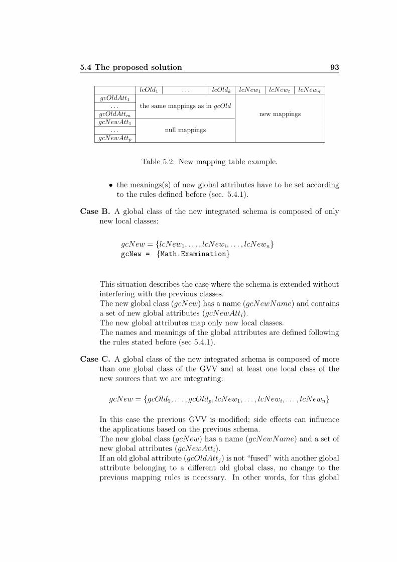
5.4 The proposed solution 93
lcOld1 . . . lcOldk lcNew1 lcNewt lcNewn
gcOldAtt1. . . the same mappings as in gcOld
gcOldAttm new mappingsgcNewAtt1
. . . null mappingsgcNewAttp
Table 5.2: New mapping table example.
• the meanings(s) of new global attributes have to be set accordingto the rules defined before (sec. 5.4.1).
Case B. A global class of the new integrated schema is composed of onlynew local classes:
gcNew = {lcNew1, . . . , lcNewi, . . . , lcNewn}gcNew = {Math.Examination}
This situation describes the case where the schema is extended withoutinterfering with the previous classes.The new global class (gcNew) has a name (gcNewName) and containsa set of new global attributes (gcNewAtti).The new global attributes map only new local classes.The names and meanings of the global attributes are defined followingthe rules stated before (sec 5.4.1).
Case C. A global class of the new integrated schema is composed of morethan one global class of the GVV and at least one local class of thenew sources that we are integrating:
gcNew = {gcOld1, . . . , gcOldp, lcNew1, . . . , lcNewi, . . . , lcNewn}
In this case the previous GVV is modified; side effects can influencethe applications based on the previous schema.The new global class (gcNew) has a name (gcNewName) and a set ofnew global attributes (gcNewAtti).If an old global attribute (gcOldAttj) is not “fused” with another globalattribute belonging to a different old global class, no change to theprevious mapping rules is necessary. In other words, for this global

94 Integration of new sources in the MOMIS system
attribute all the previous mappings, w.r.t. the previous lcOld, arevalid. Otherwise we have to define new mappings.
It can be demonstrated that these are the three only possible cases. Thisclaim remains true only if the same clustering parameters are used duringthe new integration process.
5.5 Necessary changes
The present framework of the MOMIS system is not able to accomplish thepresented approach, so some changes are necessary. Now we try to analyzethe main modifications that have to be designed and realized in the future.
According to the approach we have illustrated, two main parts of inter-vention are: I) global schema annotation and II) new sources integration.These phases are managed by SI-Designer component, therefore changes willinterest its modules (see sec. 4.1).
I) Global Schema annotation.First of all, the global class building and refinement process have to be
changed in order to allow the designer to annotate global classes and at-tributes. The SI-Designer modules involved are:
• ARTEMIS: at present this module computes global clusters exploitingaffinity indexes. New features have to be added to guide the designerafter the creation of the global classes. In particular we need featuresin order to:
– select a significant name for each global class, suggesting possiblenames to the designer according to the rules explained before insec. 5.4.1;
– assign the correct meanings to each global class suggesting possiblemeanings to the designer according to rules in sec. 5.4.1.
• TUNIM: at present this module computes global attributes and helpsthe designer during the refinement phase. New features have to beadded to accomplish the new rules defined in sec. 5.4.1, that is toenrich global attributes with meanings derived from local attributesannotation. In particular we need features in order to:
– select a significant name for each global attribute;

5.6 Critical analysis of the proposed process 95
– assign the correct meanings to each global attribute suggestingpossible meanings to the designer according to rules in sec. 5.4.1.
II) New sources’ integration.After the enrichment process we need to modify the integration process
to be able to integrate new sources according to the proposal of sec. 5.4.2.Mainly we have to modify:
• SAM: at present this module allows the designer to import sources tobe integrated. New features have to be added to import the previousGVV and to treat it as candidate source.
• SIM: at present this module extracts Common Thesaurus relationshipsfrom the local schemata and infers new relationships using ODB-Tools.Changes are necessary to exclude that the module treats the previousGVV as a normal schema.
• SLIM: this module allows the designer to annotate the local terms.We have to modify the module in order to exploit the global schemaannotation.
5.6 Critical analysis of the proposed process
We have introduced a new integration process approach, now we present someconsiderations about advantages and drawbacks we have noticed during thestudy.
Benefits :
• The process does not restart from scratch and therefore the de-signer’s effort and the computational effort are reduced.
• The process exploits the knowledge acquired during the previousintegration sessions (especially annotation); the time for integrat-ing is remarkably reduced.
• The previous schema is preserved as much as possible from use-less changes and therefore the possible side effects on the basedapplications are reduced.
• The present methodology of MOMIS is preserved, only some ad-ditions and modification are necessary.

96 Integration of new sources in the MOMIS system
Drawbacks :
• We must annotate the GVV, before integrating new sources.
• The mistakes of the previous integration session can propagate tothe new schema.
• The new GVV is based on the previous one, and then it could notrepresent all the local sources in the best way.
• Repeated sessions of integration can reduce the expressive powerof the integrated schema.

Chapter 6
Semantic Web projects
All around the world several universities, organizations, research communi-ties started projects related to Semantic Web. In this chapter we will presentsome projects and languages of particular interest for this thesis. To realizethis overview we have chosen the most important works or the most cited pa-pers in literature and we have tried to understand how the dynamics problemis faced and which are the most valuable proposals to solve it. This presenta-tion is not complete and exhaustive; we have studied these projects in orderto evaluate our approach to dynamics. Further information can be foundfollowing the links present in this chapter.
The W3C consortium has a particular group of people that are study-ing new languages (OWL Web Ontology Language for example) and newstandards related to the new tools that begin to appear on the web. TheEuropean Union by means of the IST (Information Society Technologies)Programme supports different projects involved in the same area of interest;we will give information about OntoWeb and On-To-Knowledge thathave done many studies and involve many researchers from academic andindustrial area. Some important universities are also involved in the study ofthe problem. Karlsruhe University is working on a framework for the man-agement of the dynamics of ontologies (MAFRA - Kaon), which is veryinteresting for its completeness. Finally we will present SHOE, a languagefor the Semantic Web proposed by J. Heflin and J. Hendler of the Universityof Maryland.
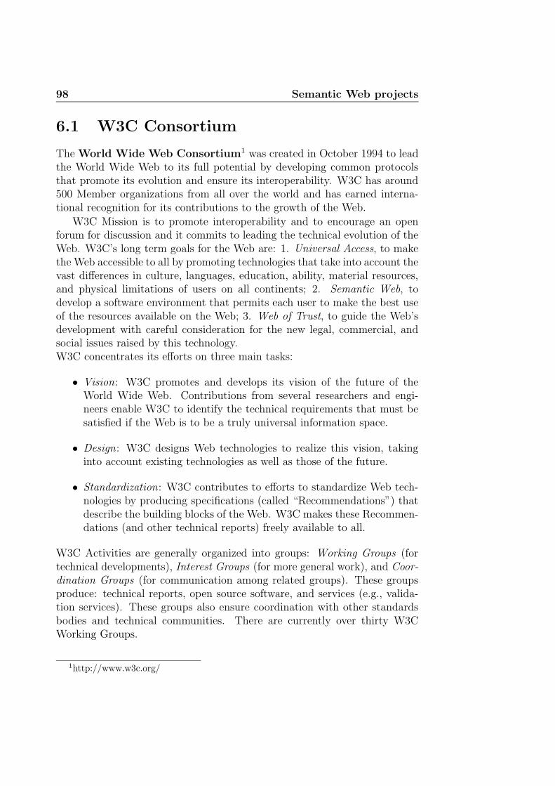
98 Semantic Web projects
6.1 W3C Consortium
The World Wide Web Consortium1 was created in October 1994 to leadthe World Wide Web to its full potential by developing common protocolsthat promote its evolution and ensure its interoperability. W3C has around500 Member organizations from all over the world and has earned interna-tional recognition for its contributions to the growth of the Web.
W3C Mission is to promote interoperability and to encourage an openforum for discussion and it commits to leading the technical evolution of theWeb. W3C’s long term goals for the Web are: 1. Universal Access, to makethe Web accessible to all by promoting technologies that take into account thevast differences in culture, languages, education, ability, material resources,and physical limitations of users on all continents; 2. Semantic Web, todevelop a software environment that permits each user to make the best useof the resources available on the Web; 3. Web of Trust, to guide the Web’sdevelopment with careful consideration for the new legal, commercial, andsocial issues raised by this technology.W3C concentrates its efforts on three main tasks:
• Vision: W3C promotes and develops its vision of the future of theWorld Wide Web. Contributions from several researchers and engi-neers enable W3C to identify the technical requirements that must besatisfied if the Web is to be a truly universal information space.
• Design: W3C designs Web technologies to realize this vision, takinginto account existing technologies as well as those of the future.
• Standardization: W3C contributes to efforts to standardize Web tech-nologies by producing specifications (called “Recommendations”) thatdescribe the building blocks of the Web. W3C makes these Recommen-dations (and other technical reports) freely available to all.
W3C Activities are generally organized into groups: Working Groups (fortechnical developments), Interest Groups (for more general work), and Coor-dination Groups (for communication among related groups). These groupsproduce: technical reports, open source software, and services (e.g., valida-tion services). These groups also ensure coordination with other standardsbodies and technical communities. There are currently over thirty W3CWorking Groups.
1http://www.w3c.org/

6.1 W3C Consortium 99
One of them works in the Semantic Web area2. They rely their activitieson the considerations that facilities to put machine-understandable data onthe Web are becoming a high priority for many communities. The Web canreach its full potential only if it becomes a place where data can be sharedand processed by automated tools as well as by people. For the Web to scale,tomorrow’s programs must be able to share and process data even when theseprograms have been designed totally independently. The Semantic Web,they state, is a vision : the idea of having data on the web defined and linkedin a way that they can be used by machines not just for display purposes, butfor automation, integration and reuse of data across various applications.
6.1.1 OWL Web Ontology Language
In November 2001, the W3C started a Web Ontology Working Groupto define a language. This group is committed to take DAML+OIL as itsstarting point and is developing a language called OWL Web OntologyLanguage. The OWL is intended to provide a language that can be usedto describe the classes and relations between them that are inherent in Webdocuments and applications. The OWL is being designed in order to pro-vide a language that can be used for applications that need to understand thecontent of information instead of just understanding the human-readable pre-sentation of content. OWL allows more machine readability of web contentthan XML, RDF, and RDF-S support by providing an additional vocabularyfor term descriptions. The OWL language is a revision of the DAML+OILweb ontology language incorporating learnings from the design and applica-tion use of DAML+OIL. OWL can be viewed as an extension of a restrictedview of the RDF language. This implies that every OWL document is anRDF document, but not all RDF documents are OWL documents.
OWL is a language for defining Web ontologies and their associatedknowledge bases. In OWL, an ontology is a set of definitions of classes,properties, and constraints on the way those classes and properties can beemployed. An OWL ontology may include the following elements :
• taxonomic relations between classes ;
• datatype properties, descriptions of attributes of elements of classes;
• object properties, descriptions of relations between elements of classes;
2http://www.w3c.org/sw/

100 Semantic Web projects
and, to an inferior degree:
• instances of classes;
• instances of properties.
Datatype properties and object properties are collectively the properties ofa class.
A set of OWL assertions loaded into a reasoning system is called a knowl-edge base (KB). These assertions may include facts about individuals that aremembers of classes, as well as various derived facts, facts not literally presentin the original textual representation of the ontology, but entailed (logicallyimplied) by the semantics of OWL. These assertions may be based on a singleontology or multiple distributed ontologies that have been combined usingOWL mechanisms.
OWL is a set of three, increasingly complex languages.
OWL Lite has been defined with the intention of creating a simple languagethat will satisfy users primarily needing a classification hierarchy andsimple constraint features. For example, while it supports cardinalityconstraints, it only permits cardinality values of 0 or 1.
OWL DL includes the complete OWL vocabulary, interpreted under a num-ber of simple constraints. Primary among these is type separation.Class identifiers cannot simultaneously be properties or individuals.Similarly, properties cannot be individuals. OWL DL is so named dueto its correspondence with description logics.
OWL Full includes the complete OWL vocabulary, interpreted more broadlythan in OWL DL, with the freedom provided by RDF. In OWL Fulla class can be treated simultaneously as a collection of individuals(the class extension) and as an individual in its own right (the classintension). Another significant difference from OWL DL is that aDatatypeProperty can be marked as an InverseFunctionalProperty.
An OWL ontology is made up of several components, some of which areoptional, and some of which may be repeated. Now a simple example of anOWL ontology is presented.
<rdf:RDF
xmlns ="http://www.example.org/wine#"
xmlns:vin ="http://www.example.org/wine#"
xmlns:food="http://www.example.org/food#"

6.1 W3C Consortium 101
xmlns:owl ="http://www.w3.org/2002/07/owl#"
xmlns:rdf ="http://www.w3.org/1999/02/22-rdf-syntax-ns#"
xmlns:rdfs="http://www.w3.org/2000/01/rdf-schema#"
xmlns:xsd ="http://www.w3.org/2000/10/XMLSchema#"
xmlns:dte ="http://www.example.org/wine-dt#">
A typical OWL ontology begins with a namespace declaration. The first twodeclarations identify the namespace associated with this ontology. The firstmakes it the default namespace, stating that unprefixed elements and emptyURI references refer to the current ontology. To state the beginnings of theontology we use
<owl:Ontology rdf:about="http://www.example.org/wine">
<rdfs:comment>An example OWL ontology</rdfs:comment>
<owl:versionInfo>
$Id: Overview.html,v 1.2 2002/11/08 16:42:25 connolly Exp $
</owl:versionInfo>
<owl:imports rdf:resource=
"http://www.w3.org/TR/2002/WD-owl-guide-20021104/food.owl"/>
A simple class Wine sub-class of PotableLiquid. The rdfs:label entryprovides an optional human readable name for this class.
<owl:Class rdf:ID="Wine">
<rdfs:subClassOf rdf:resource="#PotableLiquid"/>
<rdfs:label xml:lang="en">wine</rdfs:label>
<rdfs:label xml:lang="fr">vin</rdfs:label>
...
</owl:Class>
In addition to classes there are also their members. We normally think ofthese as individuals in our universe of things.
<Region rdf:ID="CentralCoastRegion" />
Some words are needed to better explain the difference between class and in-dividual. A class is simply a name and collection of properties that describea set of individuals, and individuals are the members of those sets. Thusclasses should correspond to naturally occurring sets of things in a domainof discourse, and individuals should correspond to actual entities that can begrouped into these classes.
Properties let us assert general facts about the members of classes andspecific facts about individuals. A property is a binary relation. Two types of

102 Semantic Web projects
properties are distinguished: datatype properties, relations between elementsof classes and XML datatypes; object properties, relations between elementsof two classes. When we define a property there are a number of ways torestrict the elements of the relation. The domain and range can be speci-fied. The property can be defined to be a specialization (subproperty) of anexisting property.
<owl:ObjectProperty rdf:ID="madeFromGrape">
<rdfs:domain rdf:resource="#Wine"/>
<rdfs:range rdf:resource="#WineGrape"/>
</owl:ObjectProperty>
The ontology header definition is closed with the following tag.
</owl:Ontology>
This prelude is followed by the actual definitions that make up the ontologyand is ultimately closed by
</rdf:RDF>
Many other elements can be introduced to enrich the ontology. Youcan define complex properties (symmetric, transitive, inverseOf, functional,inverseFunctional), restrictions, cardinality, ontology mapping, but the de-scription of them is out of the objective of this thesis. For further informationit is possible to visit the W3C web site. It’s important to note that the lan-guage is steadily developing and changes are frequent.Here you can find a guide to OWL: http://www.w3.org/TR/owl-guide/and here a technical reference: http://www.w3.org/TR/owl-ref/
6.2 OntoWeb
OntoWeb3: Ontology-based information exchange for Knowledge Manage-ment and Electronic Commerce. OntoWeb is a Thematic Network fundedby the European Commission. It started in June 2001 and it will end in May2004. Its contract number is IST-2000-29243. The Network is coordinatedby The Free University of Amsterdam (The Netherlands) and more than onehundred partners from academic and industrial area collaborate to the re-search. The University of Modena and Reggio E. is a member too.
3http://www.ontoweb.org/

6.2 OntoWeb 103
As we have seen in the previous section the Web is evolving towardsa new generation based on the semantics. To do this, we need ontologiesthat provide shared and common domain theories. They can be seen asmeta data that explicitly represent semantics of data in machine-processableway. Ontology-based reasoning services can operationalize this semantics toprovide various services. Ontologies help people and computers access theinformation they need, and effectively communicate with each other. Thegoal of the OntoWeb Network is to bring researchers and industry togetherto promote interdisciplinary work on the Semantic Web.
Another important aspect the project relies on, is the competitiveness ofcompanies active in this area. The business world has a high rate of changeso it is of crucial importance how effectively the companies acquire, maintain,exchange and can access to their knowledge, and whether they can deliverthe right information to the right individual or business at the right timewherever they are. Due to the impact of the Internet, many organizationsare more and more geographically dispersed and organized around virtualteams. Such organizations need knowledge management and organizationalmemory tools that encourage users to understand each other’s changing con-textual knowledge and encourage collaboration while capturing, representingand interpreting the knowledge resources of their organizations. At the sametime, competitiveness of companies will also depend on the products andservices they offer. The growth of a wide range of e-commerce services,both to individuals and between businesses, is contributing to the increase ininternational trading of products and services. The ability to find, interro-gate and exchange knowledge is fundamental for B2B and B2C e-Commerce.OntoWeb will identify and publicize the ontolgy-based technologies requiredfor the promotion of knowledge management and e-Commerce.
The OntoWeb Network will be the European focal point to bring to-gether activities in the area of ontology-based methods and tools for the Se-mantic Web. It wants to help companies in the emerging business field by:
• Visioning and outlining the current state-of-the-art of the ontology-related fields in Europe and World Wide and providing a strategicguide to industrial and commercial applications.
• Cooperating with several standardization bodies to promote the de-velopment of Ontology-based Content Standardization and OntologyLanguage Standardization.
• Providing non-discriminatory access to services by individuals and busi-nesses and helping in finding and extracting information from an ex-ponentially growing network.

104 Semantic Web projects
• Organizing dissemination workshops, special interesting groups, a sci-entific journal, and training or education courses with special empha-sis on Web based applications, e-commerce, knowledge managementand information integration. It addresses aspects of know-how transferbetween academia and industry about these emerging ontology-basedtechnologies in order to gain competitive advantage in these rapidlydeveloping markets.
The project’s members are divided into Special Interest Groups (SIGs).They study a particular aspect of the project and produce deliverables toexplain their outcomes. The OntoWeb SIGs are the following:
• Content Standards (SIG1). It is coordinated by Nicola Guarino(LADSEB-CNR, Italy). This group cooperates with current initia-tives related to ontology-based content standardization, develops aframework for characterizing and comparing content standardizationefforts, pushes the current standardization initiatives towards well-defined ontology-based harmonization goals, promotes the research onfoundational aspects of ontology development and stimulates the trans-fer of research on ontology development from academia to industry.
• Ontology Language Standards (SIG2). It is coordinated by IanHorrocks (University of Manchester, UK) and Frank van Harmelen(Vrije Universiteit Amsterdam). The mission of this group is to coop-erate with related initiatives (DAML) and standardization efforts andworking groups (W3C ontology language standardisation processes).To disseminate the results and transfer the research and needs betweenacademia and industry. To provide a forum for cooperation in thedevelopment of language extensions and the initiation of further stan-dardization efforts.
• Enterprise-Standard Ontology Environments (SIG3). The re-sponsible persons for this SIG are Asuncion Gomez-Perez (Universityof Marid, Spain) and Mike Brown (SemanticEdge, Germany). They tryto support a dialog for the development of Quality Requirements forenterprise-standard ontology environments. They promote the effectiveapplication of ontology technology in modern enterprises’ informationtechnology systems and provide an open forum to promote synergy andcooperation amongst the ontology technology providers and industrialontology users.
• Industrial Applications (SIG4). It is guided by Hans Akkermans(Vrije Universiteit Amsterdam, the Netherlands). They provide an

6.3 On-To-Knowledge 105
open forum to bridge the potential ontology-related researches withthe current electronic commerce market, for instance, B2C, B2B.
• Language Technology in Ontology Development and Use (SIG5).Paul Buitelaar, Thierry Declerck and Gunter Neumann (DFKI-LanguageTechnology, Germany) are responsible for this groups. Their main ob-jective is to define an information portal on language technology inontology development and use (as part of the OntoWeb portal). Theportal will serve as a platform for cooperation between R&D groupsin language technology and knowledge management, in order to estab-lish a common understanding of market and research needs, of relevantemerging standards, of tools and resources and related benchmarkingand evaluation efforts, and to identify priorities in NLP (Natural Lan-guage Processing) development for ontology learning and application.Finally, the portal will function also as a contact point for related userand technology communities, among which in particular the ”semantictechnology” industry.
Further information about the thematic network activities can be found onthe web portal where there are the published deliverables:URL: http://ontoweb.aifb.uni-karlsruhe.de/About/Deliverables
During this thesis we exploit in particular Deliverable D1.3 that presentsa complete survey on ontologies tools (see sec. 4.3). An interesting area ofthe portal is called “browse ontology” where you can navigate the commu-nity’s ontology and search documents or information inserting preferencesinto the search engine. Moreover a web portal provided by the University ofMadrid allows the user to find a lot of information and links of other inter-esting projects, tools, ontology and applications.URL http://babage.dia.fi.upm.es/ontoweb/wp1/OntoRoadMap/index.html
Finally we can say that this group is very active and their web portalis an important and updated reference point where a lot of information andlinks about the Semantic Web and Ontologies can be easily found.
6.3 On-To-Knowledge
On-To-Knowldege4 is the name of an European project that aims at creat-ing innovative tools for knowledge management. It is funded by the European
4http://www.ontoknowledge.org/

106 Semantic Web projects
Commission and is comprised within the EU Information Society Technolo-gies Programme (EU-IST-10132). It started in January 2000 and terminatedin June 2002. The project’s partners were: Free University of Amsterdam(NL), coordinator, British Telecom (UK), Swiss Life (CH), AIdministrator(NL), CognIT (NO), EnerSearch (SE), AIFB University of Karlsruhe (D),OntoText Lab. (BU).
Information Technology (IT), and especially the Internet/WWW, haveboosted the potential for knowledge acquisition and sharing but informationresources are heterogeneous, distributed, semi-structured, and enormous insize. So there is the need for tools of selective semantic (meaning-oriented)access.On-To-Knowledge wants to improve access to information sources and tolower costs to provide and maintaining large bodies of textual and semistruc-tured information. In order to reach that objectives they prepared tools forontology construction and interchange, they built up infrastructure for in-formation representation and they refined the means for information accessand extraction. During the project they analyzed three large case studies inorder to develop the technology according to the actual needs of large and/orvirtual organizations.
The project is now over and in the last deliverable5 (available on the website) they describe their achievements. On-To-Knowledge provides severalbreakthroughs on the way to the next generation of the web: advanced tools,an ontology language standard for the web, case studies, and knowledge man-agement methodology.Now we summarize some of the principal results. Figure 6.1 shows theOn-To-Knowledge architecture.
Tools.
A major objective of the project was to create intelligent software to supportusers in both having access to information and in the maintenance, conver-sion, and acquisition of information sources. These tools are based on athree-layer architecture around information access, information storage, andinformation generation.
QuizRDF is an ontology-based tool for knowledge discovery which combinestraditional keyword querying of WWW resources with the ability to browseand query against RDF annotations of those resources. RDF(S) and RDFare used to specify and populate an ontology and the resulting RDF anno-
5On-To-Knowledge Final Report

6.3 On-To-Knowledge 107
OntoWrapper OntoExtract
OMM BOR
Sesame
Quiz RDF
OntoShare
Spectacle
OntoEdit
User
Knowledge Engineer
OIL-Core ontology repository
Annotated Data Repository
Pers 349 Par05 car
Text, text, text, text, text
text, text
Data Repository (external)
RQL
OIL - Core
Tel About
Figure 6.1: On-To-Knowledge architecture
tations are then indexed along with the full text of the annotated resources.The resulting index permits both keyword querying against the full text ofthe document and against the literal values occurring in the RDF annota-tions, along with the ability to browse and query the ontology. This abilityto combine searching and browsing behaviors supports a typical information-seeking task more fully than “traditional” search engine technology.At the link below you can find the starting web page from where you canperform searches. The tool requires only a web browser and a networkconnection to have access to QuizRDF server. After entering a textualquery, the users are presented with a set of concepts from which they canselect in order to significantly narrow down their search results to a setthat is relevant to them. It can either be used in conjunction with anRDF repository such as Sesame or it can be used in it is own right to ex-tract RDF from source pages. QuizRDF is a fully developed prototype andhas been used in On-To-Knowledge case studies. It has been realized by

108 Semantic Web projects
BT Exact Technologies6.A detailed paper is “J. Davies, U. Krohn, and R. Weeks, QuizRDF: searchtechnology for thesemantic web. In WWW2002 workshop on RDF & Seman-tic Web Applications, 11th International WWW Conference WWW2002,Hawaii, USA, 2002”.
URL: http://i97.labs.bt.com/quizrdf-bin/rdfsearch/pmika2.89
OntoShare enables the storage of the best practice information in an on-tology and the automatic dissemination of the new best practice informationto relevant co-workers. It also allows users to browse or search the ontologyin order to find the most relevant information to the problem that they aredealing with at any given time. The ontology helps to orientate new usersand acts as a store for key learning and best practices accumulated throughexperience.In other words, OntoShare is a knowledge sharing system that allows a com-munity to share information. Users can enter information from the Web orIntranet pages as well as plain text articles. The system then notifies otherusers that might be interested (based upon user profiles) that some data hasbeen added. OntoShare is a Java application and users only need a webbrowser to use it. OntoShare has been realized by BT Exact Technologies.The starting page is at the link below.A detailed paper is “J. Davies, A. Duke, and A. Stonkus, OntoShare: Us-ing Ontologies for Knowledge Sharing. In Proceedings of the WWW2002Semantic Web workshop, 11th International WWW Conference WWW2002,Hawaii, USA, 2002”.
URL: http://i97.labs.bt.com/ontoshare/ologin
Spectacle organizes the presentation of information. This presentation isontology driven. Ontological information, such as classes or specific at-tributes of information, is used to generate exploration contexts for users.An exploration context makes it easier for users to explore a domain. Thecontext is related to certain tasks, such as finding information or buyingproducts.At present we have found on the site of AIdministrator7, the developer ofSpectacle, three specialized applications: Spectacle e-commerce, Spectacleanalysis, Spectacle enterprise.
6http://www.btexact.com/7http://www.aidministrator.nl/

6.3 On-To-Knowledge 109
Spectacle e-commerce is a development platform for the creation of web siteapplications that shows the products of a virtual store helping visitors tofind products they really want by sharing knowledge about the products inthe store. Spectacle makes it possible for visitors to explore a virtual storein order to learn what is there. Following the link below there is a web sitedemo.Spectacle enterprise is dedicated to companies with valuable informationrepositories that want to keep track of the latest information by automat-ically classifying new information. This enables workers to find and shareinformation. The process of adding new information to the system is simplewith the help of automatic classification software. In this way different usershave the information they need presented in the most useful manner, givingthem the possibility to save time in finding information.Spectacle analysis provides the qualitative and quantitative graphical analy-sis of information, in particular it helps information professionals understandtheir information collections. Spectacle analysis visually shows the cohesionwithin large collections of information, typically collections of documents. Itintegrates structured and unstructured information from document reposi-tories, web sites, databases, and other applications. Figure 6.2 shows theoutput of the Spectacle Cluster Map Viewer.A detailed paper is “Spectacle, Ch. Fluit, H. ter Horst, J. van der Meer, M.
Figure 6.2: Spectacle Cluster Map Viewer.

110 Semantic Web projects
Sabou,P. Mika, Ch. 9 (pgs. 145-160) of Towards the Semantic Web:Ontology-driven Knowledge Management, J. Davies, D. Fensel, F. vanHarmelen (eds.),John Wiley, 2002” or Deliverable D13 of On-To-Knowledge8.
URL: http://www.aidministrator.nl/spectacle/channel/summer2002?section=products/spectacle
OntoEdit makes it possible to inspect, browse, codify and modify ontolo-gies, and thus serves to support the ontology development and maintenancetask. Modelling ontologies using OntoEdit involves modelling at a concep-tual level, that is: (i) as independently of a concrete representation languageas possible, and (ii) using GUI’s representing views on conceptual structures(concepts, concept hierarchy, relations, axioms) rather than codifying con-ceptual structures in ASCII.This tool has been developed in java by Ontoprise (The Ontoprise GmbHwas founded 1999 as a spin off of the University of Karlsruhe) and it isavailable in different versions; one of them is downloadable free from the website (http://www.ontoprise.de/customercenter/software downloads/free en),other versions provide more services and plugins to enrich its features.A detailed paper is “Y. Sure et al.: OntoEdit: Collaborative Ontology En-gineering for the Semantic Web. In Proceedings of the first InternationalSemantic Web Conference 2002 – ISWC 2002” or Deliverable D3 of On-To-Knowledge9.Further information has been presented also in sec. 4.3.1.
URL: http://www.ontoprise.de/ontoedit.htm
Ontology Middleware Module (OMM) supports well-defined applica-tion programming interfaces (OMAPI) used for access to knowledge anddeals with such matters as:
• Ontology versioning, including branching;
• Security – user profiles and groups are used to control the rights foraccess, modifications and publishing;
• Meta-information and ontology lookup – support for meta-properties(such as Status, Last-Updated-By, Responsible, Comments, etc.) forwhole ontologies, as well as for separate concepts and properties. On-tology and concept lookup according to meta-information is possible;
8http://www.ontoknowledge.org/downl/del13.pdf9http://www.ontoknowledge.org/countd/countdown.cgi?del3.pdf

6.3 On-To-Knowledge 111
• Access via a number of protocols: HTTP, RMI, EJB, CORBA, andSOAP.
The Ontology Middleware Module is an enterprise back-end for formal knowl-edge management. It permits to knowledge representation and manage-ment in RDF(S) and languages structurally compatible with it, such as,DAML+OIL and OWL. OMM is an extension of Sesame.Further information can be found in Deliverable D3810.The Ontology Middleware is open source and is available for download andcontributions at http://sourceforge.net/projects/sesame/It has been developed by the OntoText Lab11. On the web site a workingdemo version is also present.
URL: http://www.ontotext.com/omm
Sesame is a system that permits persistent storage of RDF data and schemainformation and subsequent online querying of that information. One of themost important modules of Sesame is the query engine. This query enginesupports an OQL-style query language called RQL. RQL supports queryingof both RDF data (e.g. instances) and schema information (e.g. class hierar-chies, domains and ranges of properties). RQL also supports path-expressionsthrough RDF graphs, and can combine data and schema information in onequery.Sesame has been developed in java by AIdministrator and it needs to beinstalled locally; it is open source and can be downloaded athttp://sourceforge.net/projects/sesame/Further information can be found here: “Jeen Broekstra, Arjohn Kampman,Frank van Harmelen(2002). Sesame: A generic architecture for storing andqueryingrdf and rdf schema. In Proceedings of the First International Se-manticWeb Conference, Horrocks, I. & Hendler, J. A. (Eds.), volume 2342of Lecture Notes in Computer Science. Springer”http://www.cs.vu.nl/ frankh/postscript/ISWC02.pdfOn the Sesame web site several documents and also a demo version of thesystem are available.
URL: http://sesame.aidministrator.nl
BOR provides additional reasoning services so as to extend the functionalityprovided by SESAME. Most of the classical reasoning tasks for description
10http://www.ontoknowledge.org/downl/del38.pdf11http://www.ontotext.com/

112 Semantic Web projects
logics (DL) are available, including realization and retrieval.In other words BOR is a description logics (DL) reasoner. It has been devel-oped by OntoText in java and it has been integrated in the Sesame system.It can be downloaded from the web site with examples and tutorials. LikeSesame, it needs to be installed locally.On-To-Knowledge has studied BOR in Deliverable D40(http://www.ontoknowledge.org/downl/del40.pdf).
URL: http://www.ontotext.com/bor
CORPORUM toolset (OntoWrapper and OntoExtract) performs in-formation extraction and ontology generation. It is situated in the extractionlayer. CORPORUM has two related tasks: interpretation of natural languagetexts and extraction of specific information from free text. Whereas COR-PORUM tools can perform the former process autonomously, the latter taskrequires a user who defines business rules to extract information from tables,(phone) directories, homepages, etc.These tools allow the user to specify the pages he wants to analyze specifyingmany preferences to refine the final result (an ontology). Tools have beendeveloped as Microsoft COM objects by CognIt12 and need to be installedlocally. Following the link below you can find further documents and tutori-als.A specific paper is “R.Engels and B.A. Bremdal. CORPORUM: A Work-bench for the SemanticWeb. Semantic WebMining workshop. PKDD/ECML- 01. Freiburg, Germany,2001”.
URL: http://ontoserver.cognit.no/
Language.
Regarding the language, OIL language has been studied (cf. D. Fensel etal.: OIL: Ontology Infrastructure to Enable the Semantic Web, IEEE In-telligent System, 2001). It was designed to combine frame-like modellingprimitives with the increased expressive power, formal rigor and automatedreasoning services of an expressive description logic. OIL is “web enabled” byhaving both XML and RDFS based serializations. As part of the SemanticWeb activity of the W3C, a very simple web-based ontology language hadalready been defined, namely RDF Schema. This language only provides fa-cilities to define class and property names, inclusion axioms for both classes
12http://www.cognit.no/

6.3 On-To-Knowledge 113
and properties (subclasses and sub properties), and to define domain andrange constraints on properties. OIL has been designed to be a superset ofthe constructions in RDF Schema and the syntax of OIL has been designedsuch that any valid OIL document is also a valid RDF(S) document when allthe elements from the OIL-namespace are ignored.
For many of the applications, it is unlikely that a single language will beideally suited for all uses and all users. In order to allow users to choosethe expressive power which is appropriate to their application, and to makefuture extensions possible, a layered family of OIL languages has been con-structed. The sub-language OIL Core has been defined to be exactly thepart of OIL that coincides with RDF(S). This corresponds to full RDF(S),without some of RDFs more dubious constructions: containers and reifica-tion.During the project it was observed that some problems arise using OIL. Infact in the case studies they worked on, the domain experts often did notemploy the features of OIL to construct ontologies, they simply referred toRDF(S) or to Core-OIL. Very lightweight ontologies were constructed, some-times consisting of not much more than taxonomies of terms, often with noproperties relating them. Similarly, the automatic concept-extraction tech-nology that was employed also yielded very light-weight collections of terms,with almost no hierarchical structure and with only very general associa-tions between the concepts (of the kind: “Concept1 isStronglyRelatedToConcept2”). They try to explain these problems and they state that:
• Some case studies already started even before the first version of OILwas available;
• OIL lacks any tutorial support, any customized tool support, and anyreal practical experience. From a user point of view this makes it nearlyunusable for the moment;
• OIL is ongoing standardization efforts including high change rates. Nei-ther the user nor the tool developer can trust the current language ver-sion as being final and not just an intermediate step. Using OIL is ofhigh risk, both for users in case studies as well as for tool developers.
Methodology.
Finally, a methodology for employing ontology-based tools for knowledgemanagement applications was developed. They prepared an initial base-line methodology and applied it to the case studies they worked on. This

114 Semantic Web projects
methodology provides guidelines for introducing knowledge management con-cepts and tools into enterprises, helping knowledge providers and seekers topresent knowledge efficiently and effectively.
At the end of the project they published a book to present and promotetheir outcomes (“Towards the Semantic Web. Ontology-Driven KnowledgeManagement”. J. Davies, D. Fensel, F. van Harmelen, Wiley ed.). Theycontributed to the creation of the first International Semantic Web Confer-ence (ISWC) that took place in June 2002 in Sardinia (Italy) and they willorganize the second one in October 2003 in Florida (USA).13
The researchers that worked at the On-To-Knowledge project are stronglyinvolved in creating the international standard called OWL described before.In co-operation with the large US project DAML14 they developed a joinedconsensual sub-dialect of OIL called DAML+OIL.
6.4 MAFRA
MAFRA – A Mapping FRAmework for Distributed Ontologies [33]developed at the University of Karlsruhe. It is an interactive, incrementaland dynamic framework for mapping distributed ontologies.
As we have seen also before, the de-centralized nature of the Web makesindeed inevitable that communities will use their own ontologies to describetheir data. In this vision, ontologies are themselves distributed and the keypoint is the mediation between distributed data using mappings betweenontologies. Thus, complex mappings and reasoning about those mappingsare necessary for comparing and combining ontologies, and for integratingdata described using different ontologies.
Following the MAFRA approach, an ontology mapping process is the setof activities required to transform instances of a source ontology into instancesof a target ontology. The framework, they are building, consists of five hori-zontal modules describing the fundamental phases of mapping process. Fourvertical components run along the entire mapping process, interacting withhorizontal modules (see Figure 6.3).
Within the horizontal dimension, there are the following five modules:
Lift and Normalization. This module focuses on raising all data to bemapped onto the same representation level, coping with syntactical, struc-tural and language heterogeneity. Both ontologies must be normalized to a
13http://iswc.semanticweb.org/14http://www.daml.org/
6.4 MAFRA 115
E v o
l u t i o
n
D o m
a i n
K n o
w l e
d g e
& C
o n t r a
i n t s
C o o
p e r a
t i v e
C o n
s e n s
u s B
u i l d
i n g
G U
I
Post-processing
Execution
Semantic Bridging
Similarity
Lift & Normalization
Figure 6.3: MAFRA conceptual architecture
uniform representation, that is RDF(S), thus eliminating syntax differencesand making semantics differences between the source and the target ontol-ogy more apparent. The source and target ontologies are already representedin RDF-Schema with their instances in RDF. An essential step of this firstphase is also normalization. Three distinct ordered tasks are performed inour approach: (i) tokenization of the entities, (ii) elimination of resultingstop words and (iii) expansion of acronyms. The result is a list of normalizedlexicon.
Similarity. This module establishes similarities between entities from thesource and target ontology, thus, it supports mapping discovery. Several dif-ferent similarity measures have been proposed in literature. They adopted amulti-strategy process, that calculates similarities between ontology entitiesusing different algorithms.
Semantic Bridging. Based on the similarities computed in the previousphase, the semantic bridging phase is responsible for establishing correspon-dence between entities from the source and target ontology. It intends tospecify bridges between entities in a way that each instance represented ac-cording to the source ontology is translated into the most similar instancedescribed according to the target ontology.

116 Semantic Web projects
Execution. This module actually transforms instances from the source on-tology into target ontology by evaluating the semantic bridges defined earlier.In general two distinct modes of operation are possible, namely offline (static,one-time transformation) and online (dynamic, continuous mapping betweensource and the target) execution.
Post-processing. The post-processing component takes the results of theexecution module to check and improve the quality of the transformationresults. The most challenging task of post-processing is establishing objectidentity-recognizing that two instances represent the same real-world object.
The vertical dimension of MAFRA contains modules that interact withhorizontal modules during the overall mapping process. Four modules havebeen identified.
Evolution. This aspect focuses on keeping semantic bridges obtained bythe “Semantic Bridge” module, which must be kept in synchrony with thechanges in the source and target ontologies.
Cooperative Consensus Building. The cooperative consensus buildingaspect is responsible for establishing a consensus on semantic bridges betweentwo communities participating in the mapping process. This is a requirementsince one has to choose frequently from multiple, alternatively possible map-pings .The amount of human involvement required to achieve consensus maybe reduced by automating the mapping process as much as possible.
Domain Constraints and Background Knowledge. The quality ofsimilarity computation and semantic bridging may be dramatically improvedby introducing background knowledge and domain constraints, e.g. by usingglossaries to help identify synonyms or by using lexical ontologies, such asWordNet or domain-specific thesauri, to identify similar concepts.
Graphical User Interface. Mapping is a difficult and time consumingprocess, which is not less difficult than building an ontology itself, i.e. deepunderstanding of both conceptualizations required on human side, thus ex-tensive graphical support must be given and it is a separate issue how thiscan be achieved in an optimal way.

6.5 SHOE 117
MAFRA is currently under development within the KAON Ontologyand Semantic Web Framework. KAON15 is the Karlsruhe Ontologyand Semantic Web framework, it has been developed at the University ofKarlsruhe (Germany) and is used as a basis for several ontology-enabled re-search and industry projects. Its primary goal is to establish a platformneeded to apply Semantic Web technologies to e-commerce scenarios, knowl-edge management, automatic generation of Web portals, E-Learning etc. Tillnow they achieved the implementation of four modules of MAFRA: the au-tomatic similarity discovery module, the semantic bridging representation,the graphical user interface and the execution engine.
Navigating the KAON web portal you can find all the updated informationabout the evolution of modules (http://kaon.semanticweb.org/modules) anddownload them (http://kaon.semanticweb.org/download). Tools have beendeveloped in Java. There is also an interesting section of the site where itis possible to find demos of KAON (http://kaon.semanticweb.org/demos).Moreover there are several useful ontologies to download for testing or usingwith tools (http://kaon.semanticweb.org/ontologies). Further informationsuch as tutorials, papers, and links to other projects that use KAON areavailable in the documentation, papers and projects sections of the site.
6.5 SHOE
The Simple HTML Ontology Extension (SHOE16) is an HTML-basedknowledge representation language developed at the Computer Science De-partment of the Maryland University. SHOE is a superset of HTML whichadds the tags necessary to embed arbitrary semantic data into web pages [34].
The underlying philosophy of SHOE is that intelligent internet agentswill be able to better perform their tasks if the most useful information isprovided in a structured manner. To this end, SHOE extends HTML witha set of knowledge oriented tags that, unlike HTML tags, provide structurefor knowledge acquisition as opposed to information presentation. SHOEassociates meaning with this content by making each web page commit to oneor more ontologies. These ontologies permit the discovery of implicit knowl-edge through the use of taxonomies and inference rules, allowing informationproviders to encode only the necessary information on their web pages, andto use the level of detail that is appropriate to the context. Interoperability
15http://kaon.semanticweb.org16http://www.cs.umd.edu/projects/plus/SHOE/index.html

118 Semantic Web projects
is promoted through the sharing and reuse of ontologies. To achieve compati-bility with existing web standards, SHOEs syntax is defined as an applicationof SGML, a language that defines tag-based languages and was the influencefor HTMLs syntax. A slight variant of the syntax exists for compatibilitywith XML, and can be used by web sites that are migrating to XML.
SHOE tags are divided into two categories. First, there are tags for con-structing ontologies. SHOE ontologies are sets of rules which define whatkinds of assertions SHOE documents can make and what these assertionsmean. For example, a SHOE ontology might say that a SHOE documentcan declare that a data entity is a “dog”, and that this “dog” is permittedto have a “name”. Secondly, there are tags for annotating web documents tosubscribe to one or more ontologies, declare data entities, and make asser-tions about those entities under the rules proscribed by the ontologies. Forexample, a SHOE document subscribing to the SHOE ontology above, mightthen declare that it is all about a dog named “Fido”.
SHOE can be used to embed data from a variety of sources and for avariety of purposes. It is not intended for any particular function. However,SHOE is primarily meant to make it possible for web robots and intelligentagents to finally simplify the actions we perform every day.
SHOE is not just a meta-content language. SHOE provides a relativelyrich level of semantics and abilities, which enable web designers to embeddocuments not only with information about the overall “content” of thosedocuments but any arbitrary information at all. SHOE also allows agents tomake automatic inferences about the data they learn, provides a hierarchi-cal categorization scheme, and a sophisticated ontology mechanism designedspecifically for the web needs. SHOE tags can be used for a wide range ofagent-based functions.
SHOE does not have any pre-defined ontologies, categories, relationships,or inferences. SHOE is a language in which categories, relationships, at-tributes, inferences, etc. can be defined by ontologies, but SHOE itself doesnot define them. This is the job of ontology designers for specific tasks ordomains. However, the SHOE project offers some initial ontologies to start.SHOE Ontologies declare:
• Classifications (categories) for data entities. Classifications may inheritfrom other classifications (“Dogs are Animals”).
• Valid relationships between data entities and other data entities or sim-ple data (strings, numbers, dates, boolean). Arguments for relation-

6.5 SHOE 119
ships are typed, either by the simple data that can fill the argument,or with the classification a data entity must fall under in order to fillan argument (“Dogs can chase cats”).
• Inferences in the form of horn clauses with no negation (“If a personworks for an organization, that person automatically works for anyorganization the organization is a sub-part of”).
• Inheritance from other ontologies: ontologies may be derived from orextend zero or more outside ontologies (“The SPCA ontology extendsthe common Library of Congress ontology”).
• Versioning. Ontologies may extend previous ontology versions.
HTML pages with embedded SHOE data may:
• Declare arbitrary data entities. Usually, one of these entities is the webpage itself.
• Declare the ontologies which they will use when making declarationsabout entities (“I’m using the ’Pets’ ontology promulgated by the SPCA”).
• Categorize entities (“This entity is a dog”).
• Declare relationships between entities or between entities and data(“This entity likes to chase that entity”, “This entity’s name is ’Fido”’).
SHOE permits n-ary relations, simple inheritance in the form of classifica-tion, multi-valued relations, and a conjunctive knowledge base. It does notcurrently permit negation, disjunction, or arbitrary functions and predicates.In order to add SHOE to web pages there are two methods: I) you can usethe “Knowledge Annotator” that is a tools developed to help user that arenot familiar with the HTML and the SHOE language; II) you can add byyourself the right tags into your web (html) pages according to SHOE specifi-cations (http://www.cs.umd.edu/projects/plus/SHOE/spec.html). Here weshow a simple example of a SHOE ontology.
<HTML>
...
<BODY>
<ONTOLOGY ID="cs-dept-ontology" VERSION="1.1"
BACKWARD-COMPATIBLE-WITH="1.0">
<USE-ONTOLOGY ID="univ-ontology" VERSION="1.0" PREFIX="u"
URL="http://ontlib.org/univ_v1.0.html">

120 Semantic Web projects
...
<DEF-CATEGORY NAME="ComputerScience" ISA="u.ResearchArea">
...
<DEF-RELATION NAME="writtenIn">
<DEF-ARG POS=1 TYPE="Program">
<DEF-ARG POS=2 TYPE="ComputerLanguage">
</DEF-RELATION> ... <DEF-RENAMEFROM="u.Department"TO="Department">
<DEF-RENAME FROM="u.Chair" TO="DepartmentHead">
...
</ONTOLOGY>
</BODY>
</HTML>
The researchers of SHOE have recently moved to the MIND SWAP17
(Maryland Information and Network Dynamics Lab - Semantic Web AgentsProject) of the University of Maryland. They use OWL and DAML+OILlanguages that are partially based on SHOE.
On both web sites (SHOE and MIN SWAP) different tools are available todownload: web pages annotator (SMORE, Knowledge Annotator, RIC), con-verter (ConvertToRDF, OWL Converter, Excel2RDF). The tools have beendeveloped using Java. Moreover they have annotated web pages and theypropose a search engine that performs semantic searches exploiting SHOEfeatures.
6.6 Comments
We begin observing that many projects are on going with respect to the newissue of the Semantic Web but we think that there is not a clear and commonobjective; in some way, this fact creates some confusion in the research envi-ronment. Probably the causes of such a situation are that, on one hand, theidea of Semantic Web has created a lot of expectations but on the other handthis idea has not specified what it is necessary to become concrete. Thus theresearch has followed different trails instead of concentrating on few clearrequirements or components to build the Semantic Web.
The projects and the studies that OntoWeb and On-To-Knowledge areconducting, are heterogeneous. Specially the tools that On-To-Knowledgehas developed, cooperate to realize their architecture, but they do not form
17http://www.mindswap.org/

6.6 Comments 121
a complete environment for the management of all the aspects related to thedynamics of ontologies. Moreover the tools have been developed by manyresearch groups and therefore they are quite different.
From our point of view this fragmentation is a problem, because our firstobjective is to build a complete infrastructure that can lead the users duringall the life cycle of ontologies, from their creation, through their exploitation,their evolution, their interrogation. Concerning this we can say that thestudy of related projects has been useful to acquire important knowledgeabout the management of ontologies and to elaborate our proposal.
With respect to the results of MAFRA we can observe that the approachthey have chosen is very interesting. They try to build a framework thathelps the users in all the phases of ontologies’ management. We rememberthat they use a mapping approach to solve the problem of distributed on-tologies, while our objective is to construct a common and shared ontologyand use this integrated view to look at the represented domain.
Finally we have languages. As we have seen before, On-To-Knowledgeresearchers have encountered problems using the new language they studied,OIL, and they have tried to explain some causes. We are convinced that alsoSHOE suffers the same problems. In fact, the researchers have to be surethat the language is stable or better, standard in order to develop tools andmodels that can rely on it. Moreover both OIL and OWL (its successor) havemore than one level of use; this flexibility is necessary to help domain expertsproviding them with the most suitable level of details, during the modellingphase. Probably researchers will change their language only when a newlanguage will reach a sure status of standardization and the improvementswill be tested clearly.
In consequence of these drawbacks related to new languages, we decidedto keep ODLI3 and XML as base language to represent and to export ourdata.


Conclusions
In this work we have studied the following issues:
- the Semantic Web and the new Web scenarios;
- ontologies and their management;
- the MOMIS approach for supporting dynamics of ontologies.
One of the main objectives of this work has been the understanding of thescenarios and the problems introduced by the Semantic Web. Many re-search groups are trying to find an effective solution but it is an hard task.The infrastructure of the web is not ready yet to realize the useful expecta-tions of this new web.In particular, a lot of work has been done in finding a solution for ontologiesmanagement. We analyzed the many tools which try to face some aspectsof this issue, but there is not any tool that solves the problem in its com-pleteness and complexity. Moreover, the rapid evolving of domains and webenvironments is a further difficult problem to be faced.
We can say that the Semantic Web vision is very attracting because its princi-pal aim is to simplify the way in which people exploit the Web, but, studyingthe problem, we understood that there is not a clear research line to followyet. The scientific community, in our opinion has to work hard in order todefine solutions.
A good point in this direction is that W3C is very active in this new researcharea; an evidence of this interest is the creation of a special group with thetask to explore the problems related to the Semantic Web. They are chargedto develop facilities to put machine-understandable data on the Web.
Strictly related to these issues, we tried to understand the role that ontolo-gies have in building of the Semantic Web.
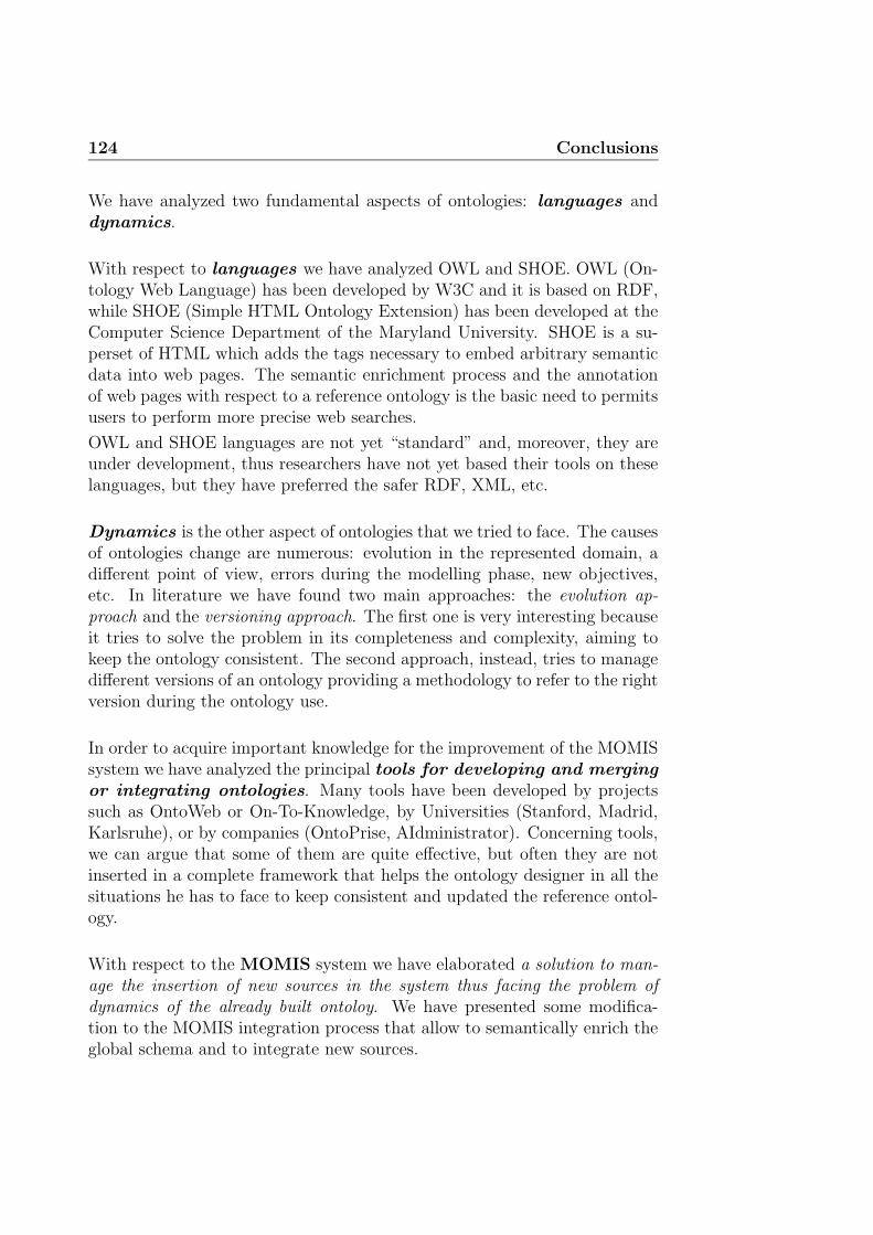
124 Conclusions
We have analyzed two fundamental aspects of ontologies: languages anddynamics.
With respect to languages we have analyzed OWL and SHOE. OWL (On-tology Web Language) has been developed by W3C and it is based on RDF,while SHOE (Simple HTML Ontology Extension) has been developed at theComputer Science Department of the Maryland University. SHOE is a su-perset of HTML which adds the tags necessary to embed arbitrary semanticdata into web pages. The semantic enrichment process and the annotationof web pages with respect to a reference ontology is the basic need to permitsusers to perform more precise web searches.
OWL and SHOE languages are not yet “standard” and, moreover, they areunder development, thus researchers have not yet based their tools on theselanguages, but they have preferred the safer RDF, XML, etc.
Dynamics is the other aspect of ontologies that we tried to face. The causesof ontologies change are numerous: evolution in the represented domain, adifferent point of view, errors during the modelling phase, new objectives,etc. In literature we have found two main approaches: the evolution ap-proach and the versioning approach. The first one is very interesting becauseit tries to solve the problem in its completeness and complexity, aiming tokeep the ontology consistent. The second approach, instead, tries to managedifferent versions of an ontology providing a methodology to refer to the rightversion during the ontology use.
In order to acquire important knowledge for the improvement of the MOMISsystem we have analyzed the principal tools for developing and mergingor integrating ontologies. Many tools have been developed by projectssuch as OntoWeb or On-To-Knowledge, by Universities (Stanford, Madrid,Karlsruhe), or by companies (OntoPrise, AIdministrator). Concerning tools,we can argue that some of them are quite effective, but often they are notinserted in a complete framework that helps the ontology designer in all thesituations he has to face to keep consistent and updated the reference ontol-ogy.
With respect to the MOMIS system we have elaborated a solution to man-age the insertion of new sources in the system thus facing the problem ofdynamics of the already built ontoloy. We have presented some modifica-tion to the MOMIS integration process that allow to semantically enrich theglobal schema and to integrate new sources.

Conclusions 125
First of all, our approach requires the annotation of the Global Virtual Viewelements (Global Classes and Global Attributes), created with the MOMISmethodology. The second phase is the integration of the new sources withthe previous GVV.
Our proposal aims to preserve as much as possible the results of the previ-ous integration phase because we assume too costly restarting the processfrom scratch. The annotation phase plays a key role to add the proper andnecessary semantics to the schema and moreover in this way we transformit in the best candidate for the integration of new sources. In other words,the new integration process is based on the exploitation of lexicon-derivedrelationships extracted after the annotation phase among previous global el-ements and new local elements of the added sources.
At present, the process that we have developed solves only the case of theinsertion of new sources. This first step is important because we have un-derstood the key role of the semantic enrichment in order to achieve goodresults. In the future the system can be extended to manage the modificationor the deletion of an integrated source.
The new integration process has been partially implemented in the MOMISsystem.
Finally we express some consideration on the importance of our work forthe SEWASIE project, in fact, MOMIS is a fundamental component of theSEWASIE system. The capability to manage dynamically the insertion ofnew sources is of great importance for the SEWASIE framework.
The efforts to extend the functionalities of the MOMIS and SEWASIE sys-tems is demonstrated also by the works done in different directions. In thefollowing we report two recent thesis.
Veronica Guidetti in her degree thesis [30] studied the possibility to extendthe WordNet lexical system. Her work wants to allow the user of SI-Designerto annotate with the right meanings new terms extracted by sources. Thisnew possibility helps the annotation and semantic enrichment process, in-creasing the probability to obtain a better integration result in the MOMIScontext. Moreover, this work is important because it opens the possibilityto extend the system to other languages different from English. Guidetti’sachievement will be integrated in the MOMIS system in the near future.

126 Conclusions
Another way to improve the completeness and the features of MOMIS is theability to find new sources to be integrated on the web. Doing this, a prob-lem is the format of web pages; HTML, in fact, is human-readable, and sowe need wrappers to transform HTML in XML that is a machine-readableformat and thus to exploit it within the MOMIS system. Lorenzo Lugli inhis thesis [35] reviews some of the most important wrappers available today.

Appendix A
The running example
In this appendix we present a complete running example of the MOMISframework.
We start introducing a schematic model of two sources (Figure A.1). Thesources derive from an university scenario:
• The first source, University (UNI), is a relational DataBase that con-tains data about personnel and student of a specific university; it hasthe following tables: Research Staff, School Member, Department,Section, Room and Article. For a given professor (in Research Staff)his department (dept code), his section (section code) and his e-mail address (e-mail) are stored. In the relation School Member theinformation name, year and faculty about students enrolled at theuniversity are stored. Department has a code (dept code), a name(dept name) and a budget. We know that a Section has a code(section code), a name (section name), a length and it is relatedto a room (room code). With reference to Room we know its code(room code), the number of seats (seats number) and we have somenotes. Finally we have articles, written by an author, with a title,a code (article code), the year of publication and the subject.
• The source Computer Science (CS) represents information about peo-ple related to the Computer Science department. This source is an ob-ject DataBase. There are nine classes: CS Person, Professor, Student,Office, Location, ClassRoom, Essay, Publication and Course. In-formation is quite similar to the first source: it stores data on professors(Professor) and students (Student), also giving the possibility to re-trieve the Office of a given professor. The class Location maintainsthe position inside the computer science department. With respect to

128 The running example
Sorgente UNIVERSITY (UNI)
Research Staff(relation,name,dept code,section code,e mail)
School Member(name,faculty,year)
Department(dept name,dept code,budget)
Section(section name,section code,length,room code)
Room(room code,seats number,notes)
Article(year,subject,author,title,journal,article code)
Sorgente COMPUTER SCIENCE (CS)
CS Person(first name,last name)
Professor:CS Person(belongs to,rank,title)
Student:CS Person(year,takes,rank)
Office(description,address,code)
Location(floor,number,building name)
Course(course name,taught by,taught in)
Essay:Publication(subject,journal)
Publication(year,title,authors)
ClassRoom(seats,code,address,notes)
Figure A.1: Reference example
students (Student), we may know the courses they take (takes), theiryear and their rank. Moreover we have information about the pub-lications (Publication) or essays (Essay) written by the computerscience’s members and of the classrooms (ClassRoom) where courses(Course) are taught.
Now we present the description of the two sources in ODLI3 language.

129
Source University UNI:
interface Research_Staff
( source relational University
extent Research_Staff
key (name)
foreign_key (dept_code) references Department (dept_code)
foreign_key (section_code) references Section (section_code) )
{ attribute string relation;
attribute string name;
attribute long section_code;
attribute long dept_code;
attribute string e_mail; };
interface Room
( source relational University
extent Room
key (room_code) )
{ attribute long seats_number;
attribute string notes;
attribute long room_code; };
interface Article
( source relational University
extent Articles
key (article_code)
foreign_key (author) references Research_Staff (name) )
{ attribute long year;
attribute string subject;
attribute string author;
attribute string title;
attribute string journal;
attribute long article_code; };
interface School_Member
( source relational University
extent School_Member
key (name) )
{ attribute long year;
attribute string name;
attribute string faculty; };
interface Section
( source relational University
extent Section
key (section_code)
foreign_key (room_code) references Room (room_code) )
{ attribute long section_code;
attribute long length;
attribute string section_name;
attribute long room_code; };
interface Department ( source relational University
extent Department
key (dept_code) )
{ attribute long dept_code;
attribute long budget;
attribute string dept_name; };

130 The running example
Source Computer Science CS:
interface Professor: CS_Person interface ClassRoom
( source object Computer_Science ( source object Computer_Science
extent Professors ) extent ClassRooms )
{ attribute string rank; { attribute long seats;
attribute string title; attribute long code;
attribute Office belongs_to; }; attribute Location address;
attribute string notes; };
interface Essay: Publication
( source object Computer_Science
extent Essays )
{ attribute string subject;
attribute string journal; };
interface Publication
( source object Computer_Science
extent Publications )
{ attribute long year;
attribute set<Professor> authors;
attribute string title; };
interface Office
( source object Computer_Science
extent Offices
key (description) )
{ attribute string code;
attribute string description;
attribute Location address; };
interface Student: CS_Person
( source object Computer_Science
extent Students )
{ attribute long year;
attribute string rank;
attribute set<Course> takes; };
interface Course
( source object Computer_Science
extent Courses )
{ attribute string course_name;
attribute Professor taught_by;
attribute ClassRoom taught_in; };
interface Location
( source object Computer_Science
extent Locations )
{ attribute long floor;
attribute long number;
attribute string building_name; };
interface CS_Person
( source object Computer_Science
extent CS_Persons
key (first_name, last_name) )
{ attribute string first_name;
attribute string last_name; };

131
The Common Thesaurus at the end of the sources analysis contains thefollowing relations. The last two column represent the module that has pro-duced the relation and if the relation is validated.
Common Thesaurus relationships
Term Rel. Term Module Validated
Computer Science.Location RT Computer Science.ClassRoom SIMA YES
University.Department RT University.Research Staff SIMA YES
University.Section RT University.Research Staff SIMA YES
University.Research Staff.name SYN University.Article.author SIMA YES
University.Research Staff RT University.Article SIMA YES
University.Room RT University.Section SIMA YES
Computer Science.Professor NT Computer Science.CS Person SIMA YES
Computer Science.Essay NT Computer Science.Publication SIMA YES
Computer Science.Student NT Computer Science.CS Person SIMA YES
Computer Science.Office RT Computer Science.Professor SIMA YES
Computer Science.Professor RT Computer Science.Publication SIMA YES
Computer Science.Location RT Computer Science.Office SIMA YES
Computer Science.Course RT Computer Science.Student SIMA YES
Computer Science.Professor RT Computer Science.Course SIMA YES
Computer Science.ClassRoom RT Computer Science.Course SIMA YES
University.Section RT Computer Science.Professor SIMB YES
University.Article RT Computer Science.Professor SIMB YES
University.Department RT Computer Science.Professor SIMB YES
Computer Science.Office RT University.Research Staff SIMB YES
Computer Science.Course RT University.Research Staff SIMB YES
Computer Science.Publication RT University.Research Staff SIMB YES
University.Room RT Computer Science.Course SIMB YES
Computer Science.Course RT University.School Member SIMB YES
Computer Science.Student RT University.Section SIMB YES
Computer Science.ClassRoom RT University.Section SIMB YES
University.Article NT University.Research Staff.relation SLIM YES
University.Article.year SYN University.School Member.year SLIM YES
University.Article.year SYN Computer Science.Publication.year SLIM YES
University.Article.year SYN Computer Science.Student.year SLIM YES
University.School Member.year SYN Computer Science.Publication.year SLIM YES
University.School Member.year SYN Computer Science.Student.year SLIM YES
Computer Science.Publication.year SYN Computer Science.Student.year SLIM YES
University.Article.author SYN Computer Science.Publication.authors SLIM NO
Computer Science.CS Person BT University.Article.author SLIM YES
Computer Science.CS Person BT Computer Science.Publication.authors SLIM YES
University.Research Staff.name SYN University.School Member.name SLIM YES
University.Research Staff.name NT University.Research Staff.relation SLIM YES
University.School Member.name NT University.Research Staff.relation SLIM YES
Computer Science.Professor.title NT University.Research Staff.name SLIM YES
Computer Science.Professor.title NT University.School Member.name SLIM YES
Computer Science.Professor.title NT University.Research Staff.relation SLIM YES
University.Research Staff SYN Computer Science.Professor SLIM YES
University.Research Staff NT Computer Science.CS Person SLIM YES
Computer Science.Location.floor RT Computer Science.Location.building name SLIM NO
Computer Science.Essay NT University.Research Staff.relation SLIM YES
Computer Science.Office.code NT University.Research Staff.relation SLIM YES
University.Section SYN University.Section.section name SLIM YES
University.Section SYN Computer Science.Course SLIM YES
University.Section SYN Computer Science.Course.course name SLIM YES
Computer Science.Course SYN University.Section.section name SLIM YES

132 The running example
Term Rel. Term Module Validated
University.Section.section name SYN Computer Science.Course.course name SLIM YES
Computer Science.Course SYN Computer Science.Course.course name SLIM YES
University.Room RT Computer Science.Location.building name SLIM YES
University.Article.title SYN Computer Science.Publication.title SLIM YES
University.Article.title NT University.Research Staff.relation SLIM YES
Computer Science.Publication.title NT University.Research Staff.relation SLIM YES
Computer Science.Professor.rank SYN Computer Science.Student.rank SLIM YES
University.School Member SYN Computer Science.Student SLIM YES
University.School Member NT Computer Science.CS Person SLIM YES
Computer Science.Office.address SYN Computer Science.ClassRoom.address SLIM YES
Computer Science.Office.address NT University.Room.room code SLIM NO
Computer Science.ClassRoom.address NT University.Room.room code SLIM NO
Computer Science.ClassRoom NT University.Room SLIM YES
University.Room.notes SYN Computer Science.ClassRoom.notes SLIM YES
University.Room.notes NT University.Research Staff.relation SLIM YES
Computer Science.ClassRoom.notes NT University.Research Staff.relation SLIM YES
Computer Science.CS Person.first name NT University.Research Staff.name SLIM YES
Computer Science.CS Person.last name NT University.Research Staff.name SLIM YES
Computer Science.CS Person.first name NT University.School Member.name SLIM YES
Computer Science.CS Person.last name NT University.School Member.name SLIM YES
University.Article.title NT University.Research Staff.name SLIM YES
University.Article.title NT University.School Member.name SLIM YES
Computer Science.Publication.title NT University.Research Staff.name SLIM YES
Computer Science.Publication.title NT University.School Member.name SLIM YES
University.Room.seats number SYN Computer Science.ClassRoom.seats SLIM YES
University.Room.seats number NT University.Research Staff.relation SLIM NO
Computer Science.ClassRoom.seats NT University.Research Staff.relation SLIM NO
University.Department SYN University.School Member.faculty SLIM YES
University.School Member.faculty SYN University.Department.dept name SLIM YES
University.Department SYN University.Department.dept name SLIM YES
University.Article.journal SYN Computer Science.Essay.journal SLIM YES
Computer Science.Publication BT University.Article.journal SLIM YES
Computer Science.Publication BT Computer Science.Essay.journal SLIM YES
University.Article NT Computer Science.Publication TRE∗ YES
∗ = Thesaurus Relations Editor.
We recall briefly the source of each type of relations (see sec. 4.1.1 for acomplete description):
• SIMA is the module that analyze the local sources schemas to findintra- and inter-schema relationships.
• SIMB is the module that checks (validates) the correctness of attributerelationships and infers new relationships using ODB-Tools.
• SLIM is the module that infers relationships exploiting the semanticannotation of the local terms using the lexical database of WordNet.
• TRE is the Thesaurus Relations Editor that guide the user insertingspecific relationships into the Thesaurus.
With respect to the annotation of the local terms, we show some examples.

133
Each term has a name and a meaning; each meaning is composed of a wordform (or lemma) and a counter that represents the sense associated withthose word form. Some terms can be annotated with more than one meaning.Below each term there is the complete WordNet sense.
Source.Class.Attribute = <name, {lemma#sense}>
Local terms annotation.
Computer_Science.CS_Person = <person,{person#1}>
person#1 = a human being
Computer_Science.Professor = <professor,{professor#1}>
professor#1 = someone who is a member of the faculty at a college or university
University.School_Member = <student,{student#1}>
student#1 = a learner who is enrolled in an educational institution
Computer_Science.Essay = <essay,{essay#1}>
essay#1 = an analytic or interpretive literary composition
Computer_Science.Publication = <publication,{publication#2}>
publication#2 = a copy of a printed work offered for distribution
University.Article = <article,{article#1}>
article#1 = nonfictional prose forming an independent part of a publication
Computer_Science.Course = <course,{course#1}>
course#1 = education imparted in a series of lessons or class meetings
University.Section = <section,{course#1}>
course#1 = education imparted in a series of lessons or class meetings
Computer_Science.Office = <office,{office#1}>
office#1 = place of business where professional or clerical duties are performed
Computer_Science.Student.first_name = <first_name,{first name#1}>
first name#1 = the name that precedes the surname
Computer_Science.Student.last_name = <last_name,{last name#1}>
last name#1 = the name used to identify the members of a family
Computer_Science.Professor.name = <name,{name#1}>
name#1 = a language unit by which a person or thing is known
Computer_Science.Professor.rank = <rank,{rank#2}>
rank#2 = relative status
134 The running example
Computer_Science.Student.rank = <rank,{rank#4}>
rank#4 = position in a social hierarchy
Computer_Science.Professor.title = <title,{title#6,tile#9}>
title#6 = an identifying appellation signifying status or function
title#9 = an appellation signifying nobility
The next step is the Clusters generation. The integration process producesseven clusters.
Clusters.
Global0 (Course)Computer Science.Course
University.Section
Global1 (Department)University.Department
Global2 (Location)Computer Science.Location
Global3 (Office)Computer Science.Office
Global4 (Person)Computer Science.CS Person
Computer Science.Professor
University.Research Staff
University.School Member
Global5 (Publication)Computer Science.Essay
Computer Science.Publication
University.Article

135
Global5 (Publication)Computer Science.ClassRoom
University.Room
Figure A.2 is a screenshot of the Clusters generation tab of the MOMISsystem; the designer can refine the automatic elaboration of the clusters.
Figure A.2: Cluster generation tab.
After the creation of clusters there is the Global Class generation; for eachglobal class the system propose a mapping table to the designer that can re-fine the proposed mapping rules. We present here the ODLI3 representationof the global classes.
Global Classes.
interface Global0 (Course) {
attribute string course_name;
mapping_rules(
Computer_Science.Course: course_name
University.Section: section_name
)

136 The running example
attribute integer length;
mapping_rules(
Computer_Science.Course: NULL
University.Section: length
)
attribute integer room_code;
mapping_rules(
Computer_Science.Course: NULL
University.Section: room_code
)
attribute integer section_code;
mapping_rules(
Computer_Science.Course: NULL
University.Section: section_code
)
attribute complex taught_by;
mapping_rules(
Computer_Science.Course: taught_by
University.Section: NULL
)
attribute complex taught_in;
mapping_rules(
Computer_Science.Course: taught_in
University.Section: NULL
)
}
interface Global1 (Department) {
attribute integer budget;
mapping_rules(
University.Department: budget
)
attribute integer dept_code;
mapping_rules(
University.Department: dept_code
)
attribute string dept_name;
mapping_rules(
University.Department: dept_name
)
}

137
interface Global2 (Location) {
attribute string building_name;
mapping_rules(
Computer_Science.Location: building_name
)
attribute integer floor;
mapping_rules(
Computer_Science.Location: floor
)
attribute integer number;
mapping_rules(
Computer_Science.Location: number
)
}
interface Global3 (Office) {
attribute complex address;
mapping_rules(
Computer_Science.Office: address
)
attribute string code;
mapping_rules(
Computer_Science.Office: code
)
attribute string description;
mapping_rules(
Computer_Science.Office: description
)
}
interface Global4 (Person) {
attribute complex belongs_to;
mapping_rules(
Computer_Science.CS_Person: NULL
Computer_Science.Professor: belongs_to
Computer_Science.Student: NULL
University.Research_Staff: NULL
University.School_Member: NULL
)
attribute integer dept_code;
mapping_rules(
Computer_Science.CS_Person: NULL

138 The running example
Computer_Science.Professor: NULL
Computer_Science.Student: NULL
University.Research_Staff: dept_code
University.School_Member: NULL
)
attribute string e_mail;
mapping_rules(
Computer_Science.CS_Person: NULL
Computer_Science.Professor: NULL
Computer_Science.Student: NULL
University.Research_Staff: e_mail
University.School_Member: NULL
)
attribute string faculty;
mapping_rules(
Computer_Science.CS_Person: NULL
Computer_Science.Professor: NULL
Computer_Science.Student: NULL
University.Research_Staff: NULL
University.School_Member: faculty
)
attribute string name;
mapping_rules(
Computer_Science.CS_Person: first_name AND last_name
Computer_Science.Professor: first_name AND last_name
Computer_Science.Student: first_name AND last_name
University.Research_Staff: name
University.School_Member: name
)
attribute string rank;
mapping_rules(
Computer_Science.CS_Person: NULL
Computer_Science.Professor: rank
Computer_Science.Student: rank
University.Research_Staff: NULL
University.School_Member: NULL
)
attribute string relation;
mapping_rules(
Computer_Science.CS_Person: NULL
Computer_Science.Professor: NULL
Computer_Science.Student: NULL
University.Research_Staff: relation

139
University.School_Member: NULL
)
attribute integer section_code;
mapping_rules(
Computer_Science.CS_Person: NULL
Computer_Science.Professor: NULL
Computer_Science.Student: NULL
University.Research_Staff: section_code
University.School_Member: NULL
)
attribute array takes;
mapping_rules(
Computer_Science.CS_Person: NULL
Computer_Science.Professor: NULL
Computer_Science.Student: takes
University.Research_Staff: NULL
University.School_Member: NULL
)
attribute string title;
mapping_rules(
Computer_Science.CS_Person: NULL
Computer_Science.Professor: title
Computer_Science.Student: NULL
University.Research_Staff: NULL
University.School_Member: NULL
)
attribute integer year;
mapping_rules(
Computer_Science.CS_Person: NULL
Computer_Science.Professor: NULL
Computer_Science.Student: year
University.Research_Staff: NULL
University.School_Member: year
)
}
interface Global5 (Publication) {
attribute integer article_code;
mapping_rules(
Computer_Science.Essay: NULL
Computer_Science.Publication: NULL
University.Article: article_code
)

140 The running example
attribute array authors;
mapping_rules(
Computer_Science.Essay: authors
Computer_Science.Publication: authors
University.Article: author
)
attribute string journal;
mapping_rules(
Computer_Science.Essay: journal
Computer_Science.Publication: NULL
University.Article: journal
)
attribute string subject;
mapping_rules(
Computer_Science.Essay: subject
Computer_Science.Publication: NULL
University.Article: subject
)
attribute string title;
mapping_rules(
Computer_Science.Essay: title
Computer_Science.Publication: title
University.Article: title
)
attribute integer year;
mapping_rules(
Computer_Science.Essay: year
Computer_Science.Publication: year
University.Article: year
)
}
interface Global6 (Room) {
attribute complex address;
mapping_rules(
Computer_Science.ClassRoom: address
University.Room: NULL
)
attribute integer code;
mapping_rules(
Computer_Science.ClassRoom: code
University.Room: room_code
)

141
attribute string notes;
mapping_rules(
Computer_Science.ClassRoom: notes
University.Room: notes
)
attribute integer seats;
mapping_rules(
Computer_Science.ClassRoom: seats
University.Room: seats_number
)
}
Each Global Class can be shown as a table where each row of the first columnrepresents the global attributes while the others columns represent the localclasses that belong to the global class. Each element of the table representthe local attributes mapped by the corresponding global attribute. We showalso a screenshot of the MOMIS tab that help the designer in the refinementof the mapping tables.
Global Class Global4 (Person)
CS CS CS UNI UNI
CS Person Professor Student Research Staff School Member
belongs to null belongs to null null null
dept code null null null dept code null
e mail null null null e mail null
faculty null null null null faculty
name first name and first name and first name and name name
last name last name last name
rank null rank rank null null
relation null null null relation null
section code null null null section code null
title null title null null null
year null null year null year
Figure A.3 shows the SI-Designer’s tab where the mapping tables of theglobal attributes are refined by the designer.
Following the proposal that we have formulated for the integration of newsources, we have first to annotate the terms (classes and attributes) of theGlobal Schema (GVV). Doing this we respect the rules presented in section5.4.1. Some results are here provided.
Global terms annotation.

142 The running example
Figure A.3: Global Attributes refinement.
Global0 = <course,{course#1}>
course#1 = education imparted in a series of lessons or class meetings
Global3 = <office,{office#1}>
office#1 = place of business where professional or clerical duties are performed
Global4 = <person,{person#1,professor#1,student#1}>
person#1 = a human being
professor#1 = someone who is a member of the faculty at a college or university
student#1 = a learner who is enrolled in an educational institution
Global5 = <publication,{essay#1,publication#2,article#1}>
essay#1= an analytic or interpretive literary composition
publication#2 = a copy of a printed work offered for distribution
article#1 =nonfictional prose forming an independent part of a publication
Global4.title = <title,{title#6,tile#9}>
title#6 = an identifying appellation signifying status or function
title#9 = an appellation signifying nobility
Global4.rank = <rank,{rank#2,rank#4}>
rank#2 = relative status
rank#4 = position in a social hierarchy

143
Global4.name = <name,{first name#1,last name#1,name#1}>
first name#1 = the name that precedes the surname
last name#1 = the name used to identify the members of a family
name#1 = a language unit by which a person or thing is known
Now we present the XML schema of the new source MATH that we try tointegrate into the previous GVV.
The new source describes the information related to persons, students, courses,examinations, and papers of a math department.
Source Math
<Source name="Math" type="xml">
<Interface name="Teacher" persistent="false">
<extends name="Person"/>
<extent name="Teachers"/>
<Attribute name="rank" type="string"/>
<Attribute name="teach" type="set" collectionOf="Course"/>
<Attribute name="write" type="set" collectionOf="Paper"/>
<Attribute name="work_in" type="Office"/>
</Interface>
<Interface name="Office" persistent="false">
<extent name="Offices"/>
<Key name="PrimaryKey">
<KeyAttribute name="code"/>
</Key>
<Attribute name="code" type="string"/>
<Attribute name="section" type="string"/>
<Attribute name="floor" type="long"/>
</Interface>
<Interface name="Student" persistent="false">
<extends name="Person"/>
<extent name="Students"/>
<Attribute name="year" type="long"/>
<Attribute name="attend" type="set" collectionOf="Course"/>
</Interface>
<Interface name="Course" persistent="false">
<extent name="Courses"/>
<Attribute name="course_name" type="string"/>

144 The running example
<Attribute name="taught_in" type="ClassRoom"/>
<Attribute name="period" type="string"/>
</Interface>
<Interface name="ClassRoom" persistent="false">
<extent name="ClassRooms"/>
<Attribute name="code" type="string"/>
<Attribute name="seats" type="long"/>
<Attribute name="description" type="string"/>
</Interface>
<Interface name="Person" persistent="false">
<extent name="Persons"/>
<Key name="PrimaryKey">
<KeyAttribute name="first_name"/>
<KeyAttribute name="last_name"/>
</Key>
<Attribute name="first_name" type="string"/>
<Attribute name="last_name" type="string"/>
<Attribute name="birth_date" type="string"/>
</Interface>
<Interface name="Researcher" persistent="false">
<extends name="Person"/>
<extent name="Researcher"/>
<Attribute name="write" type="set" collectionOf="Paper"/>
<Attribute name="work_in" type="Office"/>
<Attribute name="subject" type="string"/>
</Interface>
<Interface name="Examination" persistent="false">
<extent name="Examinations"/>
<Key name="PrimaryKey">
<KeyAttribute name="candidate"/>
<KeyAttribute name="course"/>
</Key>
<Attribute name="candidate" type="Student"/>
<Attribute name="course" type="Course"/>
<Attribute name="result" type="long"/>
</Interface>
<Interface name="Paper" persistent="false">
<extent name="Papers"/>

145
<Key name="PrimaryKey">
<KeyAttribute name="title"/>
</Key>
<Attribute name="title" type="string"/>
<Attribute name="year" type="long"/>
<Attribute name="journal" type="string"/>
<Attribute name="subject" type="string"/>
</Interface>
</Source>
The integration process with the previous GVV produces the following clus-ters.
Clusters.
NewGlobal0 (Location)GVV.Location
NewGlobal1 (Department)GVV.Department
NewGlobal2 (Room)GVV.Room
Math.ClassRoom
NewGlobal3 (Office)GVV.Office
Math.Office
NewGlobal4 (Examination)Math.Examination
146 The running example
NewGlobal5 (Person)GVV.Person
Math.Person
Math.Researcher
Math.Student
Math.Teacher
NewGlobal6 (Publication)GVV.Publication
Math.Paper

Appendix B
The ODLI3 descriptionlanguage
We present here the BNF description of ODLI3 language. We illustrate onlythe syntactic elements that differ from the original ODL grammar defined inODMG-93 standard.
〈interface dcl〉 : : = 〈interface header〉{[〈 interface body〉]};[union 〈identifier〉 { 〈interface body〉 };]
〈interface header〉 : : = interface 〈identifier〉[〈inheritance spec〉][〈type property list〉]
〈inheritance spec〉 : : = : 〈scoped name〉[,〈inheritance spec〉]

148 The ODLI3 description language
Definition of local schema model: wrappers have to be able to specify source’stype and name for each model.
〈type property list〉 : : = ( [〈source spec〉][〈extent spec〉][〈key spec〉] [〈f key spec〉] [〈c key spec〉] )
〈source spec〉 : : = source 〈source type〉〈source name〉
〈source type〉 : : = relational | nfrelational| object | file| semistructured
〈source name〉 : : = 〈identifier〉〈extent spec〉 : : = extent 〈extent list〉〈extent list〉 : : = 〈string〉 | 〈string〉,〈extent list〉〈key spec〉 : : = key[s] 〈key list〉〈f key spec〉 : : = foreign key (〈f key list〉)
references 〈key list〉 [〈f key spec〉]
〈c key spec〉 : : = candidate key 〈identifier〉(〈key list〉)

149
Definition of mapping rules between global attributes and corresponding lo-cal attributes of local sources.
〈attr dcl〉 : : = [readonly] attribute[〈domain type〉]〈attribute name〉 [*][〈fixed array size〉][〈mapping rule dcl〉]
〈mapping rule dcl〉 : : = mapping rule 〈rule list〉〈rule list〉 : : = 〈rule〉 | 〈rule〉,〈rule list〉〈rule〉 : : = 〈local attr name〉 |
‘〈identifier〉’〈and expression〉 |〈union expression〉
〈and expression〉 : : = ( 〈local attr name〉 and〈and list〉 )
〈and list〉 : : = 〈local attr name〉| 〈local attr name〉 and〈and list〉
〈union expression〉 : : = ( 〈local attr name〉 union〈union list〉 on 〈identifier〉 )
〈union list〉 : : = 〈local attr name〉| 〈local attr name〉 union〈union list〉
〈local attr name〉 : : = 〈source name〉.〈class name〉.〈attribute name〉
. . .
Terms relationships inserted in the Common Thesaurus.
〈relationships list〉 : : = 〈relationship dcl〉; |〈relationship dcl〉;〈relationships list〉
〈relationships dcl〉 : : = 〈local name〉〈relationship type〉〈local name〉
〈local name〉 : : = 〈source name〉.〈local class name〉[.〈local attr name〉]
〈relationship type〉 : : = SYN | BT | NT | RT. . .

150 The ODLI3 description language
Definition of OLCD integrity constraints: rule declarations (using if thendefinition) valid for each data instance; mapping rule declarations (specifica-tion of or, and rules).
〈rule list〉 : : = 〈rule dcl〉; | 〈rule dcl〉; 〈rule list〉〈rule dcl〉 : : = rule 〈identifier〉 〈rule spec〉〈rule spec〉 : : = 〈rule pre〉 then 〈rule post〉 |
{ 〈case dcl〉 }〈rule pre〉 : : = 〈forall〉 〈identifier〉 in 〈identifier〉 :
〈rule body list〉〈rule post〉 : : = 〈rule body list〉〈case dcl〉 : : = case of 〈identifier〉 : 〈case list〉〈case list〉 : : = 〈case spec〉 | 〈case spec〉 〈case list〉〈case spec〉 : : = 〈identifier〉 : 〈identifier〉 ;
〈rule body list〉 : : = ( 〈rule body list〉 ) |〈rule body〉 |〈rule body list〉 and〈rule body〉 |〈rule body list〉 and( 〈rule body list〉 )
〈rule body〉 : : = 〈dotted name〉〈rule const op〉〈literal value〉 |〈dotted name〉〈rule const op〉〈rule cast〉 〈literal value〉 |〈dotted name〉 in〈dotted name〉 |〈forall〉 〈identifier〉 in〈dotted name〉 :〈rule body list〉 |exists 〈identifier〉 in〈dotted name〉 :〈rule body list〉
〈rule const op〉 : : = = | ≥ | ≤ | > | <〈rule cast〉 : : = (〈simple type spec〉)〈dotted name〉 : : = 〈identifier〉 | 〈identifier〉.
〈dotted name〉〈forall〉 : : = for all | forall

Appendix C
Links
Chapter 1 – The Semantic Web
Scientific Americanhttp://www.sciam.com/
Agent Linkhttp://www.agentlink.org/
Chapter 2 – SEWASIE and MOMIS
SEWASIEhttp://www.sewasie.org/
MOMIShttp://www.dbgroup.unimo.it/Momis/
Object Management Grouphttp://www.omg.org/
Chapter 3 – Ontologies
Gruber’s definition of ontologyhttp://www-ksl.stanford.edu/kst/what-is-an-ontology.html

152 Links
Chapter 4 – Ontology management -tools andprojects
OILEdhttp://oiled.man.ac.uk/
OntoEdithttp://www.ontoprise.de/ontoedit en.htm
Protege-2000 and PROMPThttp://protege.stanford.edu/
WebODEhttp://delicias.dia.fi.upm.es/webODE/
Chimaerahttp://www.ksl.stanford.edu/software/chimaera/
Chapter 6 – Semantic Web projects
World Wide Web Consortium W3Chttp://www.w3c.org/Semantic Web Working Grouphttp://www.w3c.org/sw/
OWL guidehttp://www.w3.org/TR/owl-guide/OWL technical referencehttp://www.w3.org/TR/owl-ref/
OntoWebhttp://www.ontoweb.org/http://babage.dia.fi.upm.es/ontoweb/wp1/OntoRoadMap/index.htmlOntoWeb deliverableshttp://ontoweb.aifb.uni-karlsruhe.de/About/Deliverables
On-To-Knowledgehttp://www.ontoknowledge.org/

153
BT Exact Technologieshttp://www.btexact.com/
AIdministratorhttp://www.aidministrator.nl/
OntoEdithttp://www.ontoprise.de/ontoedit.htm
OntoText Labhttp://www.ontotext.com/
Ontology Middleware Modulehttp://www.ontotext.com/omm
Sesamehttp://sesame.aidministrator.nlhttp://sourceforge.net/projects/sesame/
BORhttp://www.ontotext.com/bor
CognIthttp://www.cognit.no/
CORPORUMhttp://ontoserver.cognit.no/
International Semantic Web Conference (ISWC)http://iswc.semanticweb.org/
DAMLhttp://www.daml.org/
KAONhttp://kaon.semanticweb.org
Simple HTML Ontology Extension (SHOE)http://www.cs.umd.edu/projects/plus/SHOE/index.html

154 Links
SHOE specificationshttp://www.cs.umd.edu/projects/plus/SHOE/spec.html
MIND SWAPhttp://www.mindswap.org/

Bibliography
[1] J. Hendler, O. Lassila, and T. Berners-Lee. The semantic web, a newform of web content that is meaningful to computers will unleash arevolution of new possibilities. Scientific American, May 2001.
[2] T. R. Gruber. A translation approach to portable ontology specifica-tions. In Knowledge Acquisition, volume 5, pages 199–220, 1993.
[3] M. Wooldridge and N.R. Jennings. Intelligent agents: Theories andpractice. The Knowledge Engineering Review, 10(2):115–152, 1995.
[4] S. Bergamaschi, S. Castano, and M. Vincini. Semantic integration ofsemistructured and structured data sources. SIGMOD Records, 28(1),March 1999.
[5] Domenico Beneventano, Sonia Bergamaschi, Silvana Castano, AlbertoCorni, R. Guidetti, G. Malvezzi, Michele Melchiori, and MaurizioVincini. Information integration: The momis project demonstration.In Amr El Abbadi, Michael L. Brodie, Sharma Chakravarthy, Umesh-war Dayal, Nabil Kamel, Gunter Schlageter, and Kyu-Young Whang,editors, VLDB 2000, Proceedings of 26th International Conference onVery Large Data Bases, September 10-14, 2000, Cairo, Egypt, pages611–614. Morgan Kaufmann, 2000.
[6] S. Bergamaschi, S. Castano, D. Beneventano, and M. Vincini. Seman-tic integration of heterogeneous information sources. Special Issue onIntelligent Information Integration, Data and Knowledge Engineering,36(1):215–249, 2001.
[7] I. Benetti, D. Beneventano, S. Bergamaschi, F. Guerra, and M. Vincini.An information integration framework for e-commerce. IEEE IntelligentSystems Magazine, Jannuary/February 2002.
[8] D. Beneventano, S. Bergamaschi, C. Sartori, and M. Vincini. Odb-tools:a description logics based tool for schema validation and semantic query

156 BIBLIOGRAPHY
optimization in object oriented databases. In Sesto Convegno AIIA -Roma, 1997.
[9] A.G. Miller. Wordnet: A lexical database for english. Communicationsof the ACM, 38(11):39–41, 1995.
[10] Castano S., De Antonellis V., and De Capitani Di Vimercati S. Globalviewing of heterogeneous data sources. IEEE Transactions TKDE,(13(2)):277–297, 2001.
[11] R. Hull and R. King et al. Arpa i3 reference architecture, 1995. Availableat http://www.isse.gmu.edu/I3 Arch/index.html.
[12] V. Tamma. An Ontology Model supporting Multiple Ontologies forKnowledge sharing. PhD thesis, Department of Computer Science, Uni-versity of Liverpool, 2001.
[13] N. Guarino. Formal ontologies and information systems. In Proceedingsof the International Conference on Formal Ontology in Information Sys-tems (FOIS’98), Trento, Italy, june 1998.
[14] P. Borst. Construction of Engineering ontologies for knowledge sharingand reuse. PhD thesis, University of Twente, Centre for Telematica andInformation Technology, 1997.
[15] R. Studer, V.R. Benjamins, and D. Fensel. Knowledge engineering,principles and methods. In Data and Knowledge Engineering, volume 25,pages 161–197, 1998.
[16] R. Neches, R.E. Fikes, T. Finin, T.R. Gruber, R. Patil, and T. Senator.Enabling technology for knowledge sharing. AI Magazine, 12(3):36–56,1991.
[17] A. Bernaras, I. Laresgoiti, and J. Corera. Building and reusing ontologiesfor electrical network applications. In W. Wahlster, editor, Proceedingsof the 12th European Conference on Artificial Intelligence (ECAI), pages298–302, Chichester, England, 1996. John Wiley Sons, Ltd.
[18] B. Swartout, R. Patil, K. Knight, and T. Russ. Towards distributeduse of largescale ontologies. In University of Calgary, editor, In Pro-ceedings of Tenth Knowledge Acquisition for Knowledge-Based SystemsWorkshop (KAW), Banff, Alberta, Canada, 1996.
[19] M. Uschold. Knowledge level modelling: concepts and terminology.Knowledge Engineering Review, 1998.

BIBLIOGRAPHY 157
[20] G. van Heijst, A.Th. Schreiber, and B.J. Wielinga. Using explicit on-tologies in kbs development. International Journal of Human-ComputerStudies, 45:184–292, 1997.
[21] M. Uschold and M. Gruninger. Ontologies: principles, methods, andapplications. Knowledge Engineering Review, 11(2):93–155, 1996.
[22] A. Farquhar, R. Fikes, and J. Rice. The ontolingua server: a tool forcollaborative ontology construction. International Journal of Human-Computer Studies, 46:707–728, 1997.
[23] O. Lassila and D. McGuinness. The role of frame-based representationon the semantic web. Electronic Transactions on Artificial Intelligence(ETAI) Journal: area The Semantic Web, To appear, 2001.
[24] M. Klein and D. Fensel. Ontology versioning on the semantic web. InInternational Semantic Web Working Symposium (SWWS), pages 75–91, Stanford University, USA, July 30 - August 1 2001.
[25] Ljiljana Stojanovic and Boris Motik. Ontology evolution within ontol-ogy editors. In 2002 in 13th International Conference on Knowledge En-gineering and Knowledge Management (EKAW2002), Siguenza, Spain,October 1-4 2002.
[26] L. Stojanovic, A. Maedche, B. Motik, and N. Stojanovic. User-drivenontology evolution management. In 13th International Conferenceon Knowledge Engineering and Knowledge Management (EKAW2002),Siguenza, Spain, October 1-4 2002.
[27] N. F. Noy and D. McGuinness. Ontology development 101: A guideto creating your first ontology. Technical Report KLS-01-05, StandfordKSL, 2000.
[28] Y. Sure. On-to-knowledge – ontology based knowledge managementtools and their application. German Journal Kuenstliche Intelligenz,Special Issue on Knowledge Management, (1/02), 2002.
[29] S. Castano and V. De Antonellis. Deriving global conceptual viewsfrom multiple information sources. In preProc. of ER’97 PreconferenceSymposium on Conceptual Modeling, Historical Perspectives and FutureDirections, 1997.
[30] Veronica Guidetti. Intelligent information integration systems: ex-tending lexicon ontology. Master’s thesis, Universita di Modena

158 BIBLIOGRAPHY
e Reggio Emilia, Facolta di Ingegneria, corso di laurea in In-gegneria Informatica, Modena, Italy, 2001-2002. Available fromhttp://www.dbgroup.ing.unimo.it/.
[31] Asuncion Gomez Perez. A survey on ontology tools. Deliverable 1.3,OntoWeb Ontology-based information exchange for knowledge manage-ment and electronic commerce, IST-2000-29243, May 2002.
[32] Natalya F. Noy and Mark A. Musen. Evaluating ontology-mappingtools: Requirements and experience. In 2002 in 13th InternationalConference on Knowledge Engineering and Knowledge Management(EKAW2002), Siguenza, Spain, October 1-4 2002.
[33] A. Maedche, B. Motik, N. Silva, and R. Volz. Mafra-a mappingframework for distributed ontologies. In 13th International Conferenceon Knowledge Engineering and Knowledge Management (EKAW2002),Siguenza, Spain, October 1-4 2002.
[34] J. Heflin and J. Hendler. Dynamic ontologies on the web. In AAAI/MITPress, editor, 7th National Conference on Artificial Intelligence (AAAI-2000), pages 443–449, Menlo Park, CA, USA, 2000.
[35] Lorenzo Lugli. Integrazione di sorgenti html in momis: Analisicomparativa degli strumenti esistenti. Master’s thesis, Universita diModena e Reggio Emilia, Facolta di Ingegneria, corso di laurea inIngegneria Informatica, Modena, Italy, 2001-2002. Available fromhttp://www.dbgroup.ing.unimo.it/.