onondaga county, ny€¦ · 3.3 moving bed biofilm reactor (mbbr) pretreatment ... clarification,...
TRANSCRIPT

Onondaga County, NY Oak Orchard Wastewater Treatment Plant
Capacity Evaluation
July 2013


Table of Contents
1. Introduction.......................................................................................................................................... 1
2. Existing Facilities ................................................................................................................................. 2 2.1 Current Plant Flows and Loads ................................................................................................ 2
2.2 Current Plant Performance ....................................................................................................... 4
2.3 Current Unit Process Loadings ................................................................................................. 7
3. Screening of Alternatives .................................................................................................................. 10 3.1 Plant Re-Rate ......................................................................................................................... 10
3.2 Magnetite Ballasted Settling ................................................................................................... 10
3.3 Moving Bed Biofilm Reactor (MBBR) Pretreatment ................................................................ 12
3.4 Integrated Fixed-Film Activated Sludge (IFAS) Post-Treatment ............................................ 13
3.5 Hybrid Activated Sludge (HYBACS) Roughing Pretreatment ................................................. 15
3.6 Membrane Bioreactor (MBR) .................................................................................................. 16 3.7 Full IFAS Conversion .............................................................................................................. 18
3.8 Webitat Media in Effluent Lagoons ......................................................................................... 19
3.9 Alternatives Rating .................................................................................................................. 20
3.10 Other Alternatives ................................................................................................................... 21
4. Detailed Alternatives Evaluation ....................................................................................................... 23 4.1 Magnetite Ballasted Settling ................................................................................................... 23
4.2 MBBR Pretreatment ................................................................................................................ 25
4.3 IFAS Post-Treatment .............................................................................................................. 26
4.4 BioWin Modeling – Treatment Capacity Comparison ............................................................. 28
5. Estimate of Probable Construction Costs ......................................................................................... 31 5.1 General Assumptions.............................................................................................................. 31
5.2 Magnetite Ballasted Settling Assumptions ............................................................................. 31
5.3 MBBR Pretreatment Assumptions .......................................................................................... 31
5.4 IFAS Post-Treatment Assumptions ........................................................................................ 32
5.5 Operations and Maintenance Costs ....................................................................................... 32 5.6 Costs ....................................................................................................................................... 32
GHD | Oak Orchard Wastewater Treatment Plant Capacity Evaluation, Onondaga County, NY 8615142.2 | i

Table Index Table 2-1 Discharge Permit Limits Table 2-2 2012 Flows and Loads Table 2-3 Primary Treatment Capacities Table 2-4 Secondary Treatment Capacities Table 4-1 MMBR Design Criteria Table 4-3 Modeling Results and Treatment Alternative Biological Treatment Capacities Table 4-4 Unit Process Capacities Table 4-2 IFAS Design Criteria Table 5-1 Summary of Capital Costs Table 5-2 Estimated O&M Costs
Figure Index
Figure 2-1 Existing Site Plan Figure 2-2 Existing Process Flow Diagram Figure 2-3 Influent Flows Figure 2-4 Influent BOD Figure 2-5 Effluent CBOD and TSS Discharge Figure 2-6 Effluent UOD Performance Figure 2-7 Effluent Ammonia Performance Figure 4-1 Magnetite Ballasted Settling Figure 4-2 Magnetite Ballasted Settling Process Flow Diagram Figure 4-3 BioMag System Process Flow Diagram Figure 4-4 Magnetite Ballasted Sludge Process Flow Diagram Figure 4-5 MBBR Pretreatment Figure 4-6 MBBR Pretreatment Process Flow Diagram Figure 4-7 IFAS Post-Treatment Figure 4-8 IFAS Post-Treatment Process Flow Diagram
Appendices Appendix A Magnetite Ballasted Settling Vendor Information Appendix B Moving Bed Biofilm Reactor (MBBR) Pretreatment Vendor Information Appendix C Integrated Fixed-Film Activated Sludge (IFAS) Post-Treatment Vendor Information Appendix D Hybrid Activated Sludge (HYBACS) Roughing Pretreatment Vendor Information Appendix E Membrane Bioreactor (MBR) Vendor Information Appendix F Full IFAS Conversion Vendor Information Appendix G Webitat Media in Effluent Lagoons Vendor Information Appendix H Cost Estimates
GHD | Oak Orchard Wastewater Treatment Plant Capacity Evaluation, Onondaga County, NY 8615142.2 | ii

1. Introduction The Oak Orchard Wastewater Treatment Plant (WWTP) is owned and operated by the Onondaga County Department of Water Environment Protection (OCDWEP). The plant service area consists of the Village of North Syracuse and portions of the Towns of Clay and Cicero. The majority of the wastewater from the service area is from residential sources with the some commercial and industrial sources.
The New York State Department of Environmental Conservation (NYSDEC) requires that an Annual Certification Form be completed for the treatment facility as part of the State Pollutant Discharge Elimination System (SPDES) discharge permit administration process. The Annual Certification Form is completed by the treatment facility SPDES discharge permit holder (OCDWEP). The intent of the certification form is to identify treatment facilities that are nearing or exceeding their design capacity for flow, influent BOD, or influent TSS loadings.
The 2012 Annual Certification Form for the Oak Orchard WWTP identified that the facility was exceeding the design capacity for influent BOD for 10 of the 12 months in 2012 but has not exceeded the influent flow or TSS capacity. Any facility exceeding design capacity loads in eight or more months of the year is required to prepare a Plan for Future Growth in accordance with 6 NYCRR Part 750-2.9(c)(2). This required plan must be submitted to the NYSDEC Regional Water Engineer no later than August 1, 2013.
OCDWEP has retained the services of GHD Consulting Services Inc. to evaluate alternatives to re-rate the Oak Orchard WWTP with an expanded capacity to handle additional wastewater loads. The alternatives evaluated were focused on technologies that could cost effectively provide increased capacity while minimizing the construction of additional tanks.
An initial screening was conducted to determine the technologies available for increasing the capacity of the treatment facility. The alternatives were ranked and the three most favorable were evaluated in more detail. In addition, the current performance of the treatment facility was evaluated to determine if a potential opportunity exists to re-rate the plant without the need for capital improvements.
GHD | Oak Orchard Wastewater Treatment Plant Capacity Evaluation, Onondaga County, NY 8615142.2 | 1

2. Existing Facilities The Oak Orchard WWTP is located on Oak Orchard Road in Clay, NY. The original facilities at this site consisted of two wastewater treatment lagoons and a chlorine disinfection system. In the late 1970s, the facilities were upgraded to provide primary and secondary treatment, as well as ammonia removal. The treatment facility currently consists of screenings and grit removal, primary clarification, high purity oxygen (HPO) activated sludge aerobic treatment followed by secondary clarification, aerated lagoon nitrification, and disinfection. A site plan of the existing treatment plant is included as Figure 2-1 and the plant process flow diagram is shown in Figure 2-2.
Several additional plant modifications were performed at the Oak Orchard WWTP in the late 1990s and early 2000s, as follows:
1. Plant access road improvements.
2. Addition of a lagoon bypass pipeline.
3. Upgrade and conversion of the coagulant feed system.
4. Addition of odor control facilities.
5. Upgrade and conversion of the disinfection system.
Planning is currently underway for upgrades to the treatment facility that include:
1. HVAC and gallery piping improvements.
2. Removal of the burning sludge system equipment.
3. Administration Building improvements.
4. Influent screen replacement.
5. Infill and abandonment of the primary and secondary flocculation tanks.
6. Clarifier equipment replacements
7. Lagoon cleaning and aeration upgrades.
Some of the planned improvements should be coordinated with the proposed capacity expansion. In particular, the secondary flocculation tanks offer the opportunity for expanded treatment if not infilled. Also, any expansion involving media (IFAS, MBBR) would require screening to at least 6 mm range with a perforated plate-type screen. The proposed climber screen replacement would not be compatible with these media addition options.
2.1 Current Plant Flows and Loads
The current influent flows and loads to the Oak Orchard WWTP were reviewed based on data provided by OCDWEP for a 52-month period from January 2009 through April 2013. During this period, the facility treated wastewater from the Oak Orchard service area plus wastewater from the Gaskin Road Pump Station. The Gaskin Road Pump Station has the ability to pump to either the Oak Orchard or Wetzel Road WWTP. Based on a previous report prepared by GHD (formerly Stearns & Wheler) in 2009, the Gaskin Road Pump Station contributes approximately 0.8 mgd of average daily flow to the Oak Orchard WWTP.
GHD | Oak Orchard Wastewater Treatment Plant Capacity Evaluation, Onondaga County, NY 8615142.2 | 2

Plot Date: Cad File No:25 July 2013 - 9:29 AM G:\86\15142\CADD\Drawings\Figures\Oak Orchard\8615142-FIG 2-1.dwg
Figure
Date
Revision
Job Number
One Remington Park Drive, Cazenovia NY 13035 USA T 1 315 679 5800 F 1 315 679 5801 E [email protected] W www.ghd.com
2-1
OAK ORCHARD WWTP
CAPACITY EVALUATION
EXISTING SITE PLAN
86-15142
A
07/2013
0
SCALE 1"=200' AT ORIGINAL SIZE
400'300200100

CAZENOVIA, NEW YORK
DATE: July 2013 JOB No.: 8615142
Oak Orchard WWTP
Figure 2-2Existing Process Flow Diagram
CHLORINE CONTACT
TANKTO OUTFALL
PRIMARYSETTLING
TANKSINFLUENTBAR RACK
AERATED GRIT
PRIMARY FLOCCULATION
TANKSSCREENING
HPO AERATIONTANKS
SECONDARY FLOCCULATION
TANKS
SECONDARY SETTLING
TANKSLAGOON 1 LAGOON 2
EXISTING PROCESSES

The average influent flow to the treatment facility over the 52-month period was 5.9 mgd. The facility has been operating well within the permitted flow of 10 mgd and therefore should be able to handle additional flow related to a capacity expansion. Figure 2-3 is a graph of the influent flow for this period.
Figure 2-3 Influent Flows
The organic load of concern for the Annual Certification is the influent BOD. The treatment facility has a stated design capacity of 14,200 lbs/day of BOD. The available sampling data available for influent BOD is limited since the SPDES permit for Oak Orchard is written around limits based on CBOD. The available individual day sampling for BOD is used in conjunction with the daily flow to determine the average influent BOD on a lbs/day basis. For the year 2012, only one BOD sample per month was taken, so this result was used to represent the monthly average. Beginning in 2013, multiple BOD samples were taken and then averaged to determine the monthly influent BOD. The influent BOD for the period of January 2012 through May 2013 is shown in Figure 2-4. During this 17-month period, there were 14 occurrences when the BOD exceeded the design capacity of 14,200 lbs/day. The average influent BOD during this period was 16,029 lbs/day.
GHD | Oak Orchard Wastewater Treatment Plant Capacity Evaluation, Onondaga County, NY 8615142.2 | 3

Figure 2-4 Influent BOD
The Annual Certification Form also addresses the influent TSS to a facility. The stated capacity for influent TSS is 16,700 lbs/day. The average TSS for over the 52-month period was 7,479, which is less than half of this value and therefore is not of concern.
2.2 Current Plant Performance
The Oak Orchard WWTP has a two-season SPDES discharge permit. The permit requires nitrification in the summer period from June 16 through October 31 with a limit for pounds of ammonia discharge and a UOD limit for concentration and pounds. The treatment facility has a good history of meeting the discharge limits. The last violations were in 2010 for fecal coliform and dissolved oxygen. However, these violations were isolated and not related to loadings on the treatment facility. The discharge permit limits are summarized in Table 2-1.
The effluent CBOD and TSS discharges are shown on Figure 2-5. The treatment facility is performing well at removing CBOD and TSS to below the discharge limit. The removal of TSS is aided by the lagoons which help to settle any TSS that is able to pass through the secondary clarifiers.
GHD | Oak Orchard Wastewater Treatment Plant Capacity Evaluation, Onondaga County, NY 8615142.2 | 4

Table 2-1 Discharge Permit Limits
Parameter Averaging
Period
Current Permit June 16 - October 31 November 1-June 15
Flow 30-day average 10 mgd 10 mgd
CBOD5 30-day average 25 mg/L 2,085 lbs/day
CBOD5 7-day average 40 mg/L 3,336 lbs/day
TSS 30-day average 30 mg/L 2,500 lbs/day 30 mg/L 2,500 lbs/day
TSS 7-day average 45 mg/L 3,750 lbs/day 45 mg/L 3,750 lbs/day
UOD 30-day average 4,289 lbs/day
Ammonia (as NH3)
30-day average 400 lbs/day
Dissolved oxygen Daily minimum 5.0 mg/L
Total phosphorus 30-day average 1.0 mg/L 1.0 mg/L
Settleable solids Daily maximum 0.3 ml/L 0.3 ml/L
pH Range 6.0 - 9.0 S.U. 6.0 - 9.0 S.U.
Fecal coliform(1) 30-day geometric mean
200/100 ml 200/100 ml
Fecal coliform(1) 7-day geometric mean
400/100 ml 400/100 ml
Chlorine residual Daily maximum 0.35 mg/L 18.4 lbs/day 0.35 mg/L 18.4 lbs/day
(1) Fecal coliform limits are in effect from May 15 to October 15.
Figure 2-5 Effluent CBOD and TSS Discharge
GHD | Oak Orchard Wastewater Treatment Plant Capacity Evaluation, Onondaga County, NY 8615142.2 | 5
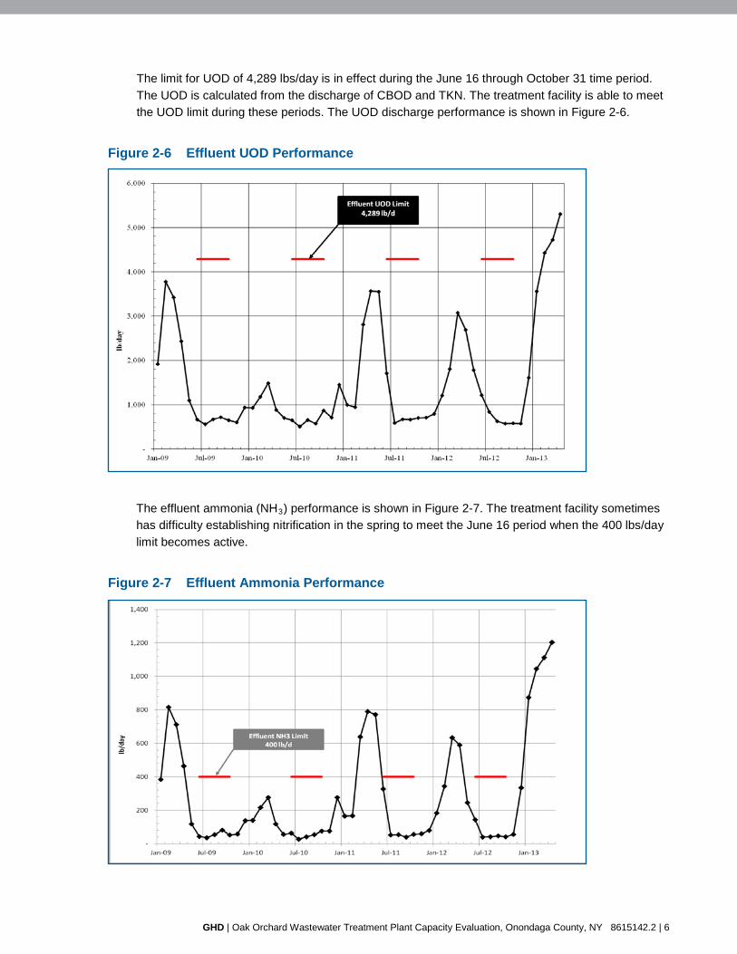
The limit for UOD of 4,289 lbs/day is in effect during the June 16 through October 31 time period. The UOD is calculated from the discharge of CBOD and TKN. The treatment facility is able to meet the UOD limit during these periods. The UOD discharge performance is shown in Figure 2-6.
Figure 2-6 Effluent UOD Performance
The effluent ammonia (NH3) performance is shown in Figure 2-7. The treatment facility sometimes has difficulty establishing nitrification in the spring to meet the June 16 period when the 400 lbs/day limit becomes active.
Figure 2-7 Effluent Ammonia Performance
GHD | Oak Orchard Wastewater Treatment Plant Capacity Evaluation, Onondaga County, NY 8615142.2 | 6

The treatment facility has been able to successfully meet the other discharge parameters, including settable solids, pH, dissolved oxygen, and total phosphorus.
2.3 Current Unit Process Loadings
The current loadings on the individual unit processes at the Oak Orchard WWTP were evaluated to determine which processes are operating below, at, or above their original design capacities. This evaluation was performed to determine which unit processes can handle higher capacity based on the current design and which process could handle additional capacity based on current performance. The current version of Recommended Standards for Wastewater Facilities, 2004 Edition (Ten-States Standards) was used as a benchmark for rated capacity of the unit processes.
The flows and loadings for 2012 were used as the basis for evaluating the current unit process loadings. The flows and loads for 2012 are summarized in Table 2-2.
Table 2-2 2012 Flows and Loads
Parameter Flow (mgd)
BOD(1)
(lbs/day) CBOD
(lbs/day) TSS
(lbs/day) TKN
(lbs/day) Average 5.58 16,300 12,905 7,999 1,584 Maximum month 7.28 20,352 13,735 9,335 1,711 Maximum day 11.41 -- -- -- -- Peak(2) 17.72 -- -- -- --
(1) BOD based on OCDWEP process sampling. (2) Peak flow based on instantaneous peak on January 27, 2012.
2.3.1 Primary Treatment
Raw wastewater entering the treatment plant passes through a manually-cleaned coarse bar screen that removes the larger debris. Downstream of this screen, the wastewater flows into two aerated grit chambers where sand, gravel, and other heavy particles are removed. After the grit chambers, there are two mechanically cleaned climber-type bar screens with more closely spaced bars that provide additional screenings removal. Another manually-cleaned bar screen is located between the two mechanical screens to provide bypass screening in the event the mechanical screens are out of service.
Screened and degritted wastewater flows to the primary treatment system to two primary clarifiers. Each clarifier is separated into three troughs for sludge collection with one common sludge hopper at the influent end of each clarifier. Ahead of the preliminary clarifiers are primary flocculation tanks which are current not used for flocculation. Aluminum sulfate (alum), is added prior to the primary clarifiers to remove phosphorus and provide enhanced settling.
The aerated grit chambers and primary clarifiers have additional unused capacity based on the current flows to the plant. A summary of the capacity of the primary treatment systems is provided in Table 2-3.
GHD | Oak Orchard Wastewater Treatment Plant Capacity Evaluation, Onondaga County, NY 8615142.2 | 7

Table 2-3 Primary Treatment Capacities
Process Design Criteria Current Loading
Current Percent
of Capacity Aerated Grit Channels Total volume Detention time – peak hour Peak flow capacity
98,000 gallons 3 minutes 47 mgd
7.96 minutes 17.72 mgd
38%
Primary Clarifiers Primary clarifier surf area Surface overflow rate - average flow Surface overflow rate - peak flow Peak flow capacity
14,400 sf 1,000 gpd/sf 2,000 gpd/ sf 28.8 mgd
388 gpd/sf 1231 gpd/sf 17.72 mgd
39% 62% 62%
2.3.2 Secondary Treatment
The Oak Orchard WWTP utilizes an HPO aeration treatment process for biological treatment. There are two HPO trains (north and south) and each train is partitioned into three stages configured in series, with each stage separated by a concrete dividing wall. Each stage of the aeration tanks contains two mechanical aerators for imparting high purity oxygen to the mixed liquor. The Oxygen Generation Building, located adjacent to the aeration tanks to the south, contains a pressure swing adsorption (PSA) system for generating the high purity oxygen used for the biological treatment process.
Downstream of the biological treatment process, the mixed liquor flows through channels to the secondary clarifiers, bypassing the four secondary flocculation tanks, which are no longer in service. A polymer solution is added to the mixed liquor upstream of the secondary clarifiers to aid in settling. There is currently no mixing equipment provided to mix the polymer with mixed liquor prior to settling. There are six rectangular secondary clarifiers at the plant, each with chain-and-flight-type mechanisms for sludge and scum collection. The six clarifiers are separated into two sets of three units each. Flow distribution to the six units is achieved through the use of channels and adjustable slide gates located at the inlet of each clarifier.
There are two treatment lagoons at the Oak Orchard WWTP. These lagoons were modified as part of the major plant upgrade in the 1970s to provide nitrification of the secondary effluent. The lagoons, which are configured in series, each contain aeration equipment for this purpose. The lagoons have been inadequate in providing the desired nitrification and therefore are not in use for this purpose. The aeration equipment is operated seasonally to provide the necessary effluent dissolved oxygen concentration to meet the requirements of the SPDES discharge permit.
Effluent from the secondary treatment process or the lagoon system flows to the disinfection system at the northern end of the treatment plant prior to being discharged from the facility. The disinfection system consists of two chlorine contact tanks and an adjacent Chlorination Building which houses the liquid sodium hypochlorite used for disinfection.
A summary of the capacity of the secondary treatment systems is provided in Table 2-4. The HPO aeration tanks are currently operating at high loading rate of up to 145 lbs BOD/day/1,000 cf. The mean cell residence time for the process is maintained around five days in the winter and increased
GHD | Oak Orchard Wastewater Treatment Plant Capacity Evaluation, Onondaga County, NY 8615142.2 | 8
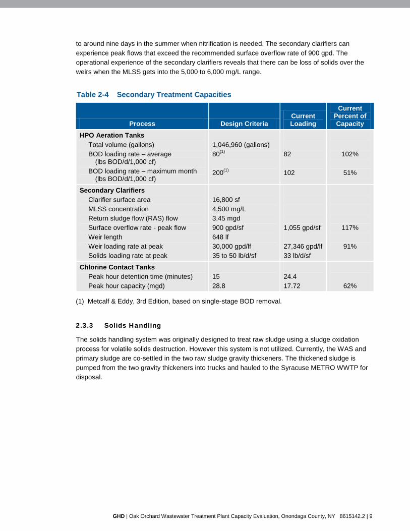
to around nine days in the summer when nitrification is needed. The secondary clarifiers can experience peak flows that exceed the recommended surface overflow rate of 900 gpd. The operational experience of the secondary clarifiers reveals that there can be loss of solids over the weirs when the MLSS gets into the 5,000 to 6,000 mg/L range.
Table 2-4 Secondary Treatment Capacities
Process Design Criteria Current Loading
Current Percent of Capacity
HPO Aeration Tanks Total volume (gallons) BOD loading rate – average
(lbs BOD/d/1,000 cf) BOD loading rate – maximum month
(lbs BOD/d/1,000 cf)
1,046,960 (gallons) 80(1) 200(1)
82 102
102%
51%
Secondary Clarifiers Clarifier surface area MLSS concentration Return sludge flow (RAS) flow Surface overflow rate - peak flow Weir length Weir loading rate at peak Solids loading rate at peak
16,800 sf 4,500 mg/L 3.45 mgd 900 gpd/sf 648 lf 30,000 gpd/lf 35 to 50 lb/d/sf
1,055 gpd/sf 27,346 gpd/lf 33 lb/d/sf
117%
91%
Chlorine Contact Tanks Peak hour detention time (minutes) Peak hour capacity (mgd)
15 28.8
24.4 17.72
62%
(1) Metcalf & Eddy, 3rd Edition, based on single-stage BOD removal.
2.3.3 Solids Handling
The solids handling system was originally designed to treat raw sludge using a sludge oxidation process for volatile solids destruction. However this system is not utilized. Currently, the WAS and primary sludge are co-settled in the two raw sludge gravity thickeners. The thickened sludge is pumped from the two gravity thickeners into trucks and hauled to the Syracuse METRO WWTP for disposal.
GHD | Oak Orchard Wastewater Treatment Plant Capacity Evaluation, Onondaga County, NY 8615142.2 | 9

3. Screening of Alternatives 3.1 Plant Re-Rate
3.1.1 Overall Process Description
The historical performance data from the facility has been reviewed and is reported in Section 2. Based on the data, the plant is outperforming the original design parameters. The plant has consistently outperformed the permit requirement for CBOD, TSS, and UOD, all while operating at a BOD loading that exceeds the original design. Some of the reasons for this include current practices of chemically enhanced primary settling, careful MLSS/solids retention time (SRT) control, and polymer addition to the final settling tanks. In addition, the lagoons provide effluent polishing during wet weather high solids periods.
If a plant consistently outperforms its anticipated design operating parameters and the effluent permit requirements are being met, the plant capacity can often times be re-rated. Based on the historical treatment at the facility it is recommended that the plant capacity loading in BOD be increased to match the current operating parameters of the facility.
3.1.2 Additional Capacity
Historical plant performance data is shown in Figures 2-5, 2-6, and 2-7. In 2012, the average monthly influent BOD to Oak Orchard was 16,300 lb/d and the maximum month BOD was 20,350 lb/d, during which time the plant met all effluent permit requirements. Therefore, it is suggested that the influent BOD capacity be increased from its current design of 14,200 to 16,300 lb/d to take credit for the current performance of the plant. Additional process improvements will be necessary to expand the plant capacity beyond the current average flows and loads.
3.1.3 Summary
The following are some of the major advantages and disadvantages of re-rating the plant. Advantages include:
1. Takes credit for current performance with the higher loads.
2. No capital expenditures are required.
Disadvantages of this alternative include
1. Does not provide capacity to handle additional growth in the service area.
3.2 Magnetite Ballasted Settling
3.2.1 Overall Process Description
Magnetite ballasted settling is a developing technology that is gaining popularity. Patented by Siemens, the BioMag™ system is an enhanced biological wastewater treatment process that uses magnetite, a common inert iron derivative, to increase the specific gravity of biological floc. The addition of magnetite has two major benefits:
1. Allows for a higher MLSS for the given clarifier area (i.e., allows higher loading rates to existing clarifiers).
GHD | Oak Orchard Wastewater Treatment Plant Capacity Evaluation, Onondaga County, NY 8615142.2 | 10

2. Typically no additional process tanks are required for increased treatment capacity.
The majority of equipment and modifications associated with the technology are for the removal and recovery of the magnetite from the waste activated sludge (WAS) prior to disposal. The magnetite is recovered from the waste stream and returned into the biological process. During this process, some magnetite is lost and additional magnetite will need to be added.
3.2.2 Application to Oak Orchard
Due to site constraints and cost concerns, eliminating new process tanks has been identified as a key cost saving criteria. Magnetite ballasted settling would eliminate the requirement for additional process tankage while effectively increasing plant loading capacity. In addition, the technology would help reduce the likelihood of clarifier upsets due to overloading.
3.2.3 Additional Capacity
The magnetite ballasted option will allow the plant to operate at greatly increased MLSS (6,000 to 10,000 mg/L) as well as improving settling characteristics and removal efficiency within its existing final clarifier capacity.
3.2.4 Incorporation into the WWTP
Based on the preliminary analysis, minimal site modifications would be required in order to accommodate the magnetite ballasted settling technology. Major modifications would include the following:
1. New magnetite storage silo.
2. Magnetite recovery equipment shall be located within the existing Sludge Process Building.
3. New pumping station to return recovered magnetite to the biological process.
4. New pumping station to return WAS to the existing solids treatment system.
Due to the higher specific gravity, in many cases, additional mixing capacity may be required to keep the biological floc in suspension. Additional mixing within the HPO biological reactors would likely be required; however, this requirement is still being investigated with the manufacturer. For the purpose of this report, it was assumed that one additional mixer would be needed in each reactor zone.
A potential concern with this alternative is that there are very few permanently installed systems for operational comparison, and none of those installations use the HPO process.
Section 4.1 provides more detailed information on this technology.
3.2.5 Summary
The following are some of the major advantages and disadvantages of the BioMag system. Advantages include:
1. Allows for increased MLSS concentrations while eliminating the need for additional secondary HPO volume and clarifier surface area.
2. Increased capacity without additional tank capacity.
3. Minimal process modifications.
GHD | Oak Orchard Wastewater Treatment Plant Capacity Evaluation, Onondaga County, NY 8615142.2 | 11

4. Minimal site disturbance.
Disadvantages of this alternative include:
1. Greater mixing required to keep mixed liquor in suspension.
2. Additional solids processing equipment required for removal and return of magnetite.
3. Minimal long-term operational experience at other facilities.
4. No current installations of BioMag™ exist which utilize the HPO process.
Vendor information for this treatment technology is provided in Appendix A.
3.3 Moving Bed Biofilm Reactor (MBBR) Pretreatment
3.3.1 Overall Process Description
The MBBR is a fixed-film treatment process that uses specifically designed plastic media, or biofilm carriers, to support the biomass for biological treatment. Aeration diffusers are used to provide the necessary oxygen for the fixed-film biomass on the media. Screens, or sieves, are required to keep the media contained within the process tanks while allowing the biologically treated wastewater to flow out of the tanks. Wastewater enters the MBBR process treatment tanks, where the fixed-film biomass growing within the internal structures of the plastic media provides biological treatment, such as BOD and ammonia removal. Solids are generated by this process when excess biofilm sloughs off of the plastic media and flows downstream to the next unit process. There is no return sludge required for this process, as all of the treatment is accomplished within the fixed film on the media.
3.3.2 Application to Oak Orchard
Based on the current BOD loading limitation present at the Oak Orchard WWTP, one of the most effective means of increasing the plant’s treatment capacity is to provide an additional pretreatment step, upstream of the existing HPO activated sludge system. This pretreatment step serves to reduce the incoming BOD loading prior to the HPO process, increasing the available capacity of the overall plant to process additional BOD loading, as well as nitrogenous loads. The increased loading can be accommodated without increasing the solids loading to the final settling tanks.
Providing an MBBR-based pretreatment process upstream of the existing HPO activated sludge process, downstream of the primary clarifiers, was evaluated as an alternative for capacity expansion at the Oak Orchard WWTP.
3.3.3 Additional Capacity
The MBBR pretreatment process will increase the treatment capacity at the Oak Orchard WWTP by increasing the total quantity of biomass available for treatment as well as the volume of process tankage under aeration. The primary purpose of this treatment process would be to remove BOD contained in the primary effluent, which would in turn allow for greater levels of BOD removal and nitrification within the existing HPO activated sludge process while not increasing solids loading to the final settling tanks.
GHD | Oak Orchard Wastewater Treatment Plant Capacity Evaluation, Onondaga County, NY 8615142.2 | 12
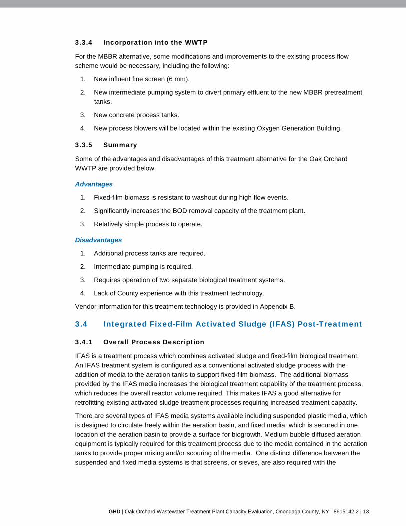
3.3.4 Incorporation into the WWTP
For the MBBR alternative, some modifications and improvements to the existing process flow scheme would be necessary, including the following:
1. New influent fine screen (6 mm).
2. New intermediate pumping system to divert primary effluent to the new MBBR pretreatment tanks.
3. New concrete process tanks.
4. New process blowers will be located within the existing Oxygen Generation Building.
3.3.5 Summary
Some of the advantages and disadvantages of this treatment alternative for the Oak Orchard WWTP are provided below.
Advantages
1. Fixed-film biomass is resistant to washout during high flow events.
2. Significantly increases the BOD removal capacity of the treatment plant.
3. Relatively simple process to operate.
Disadvantages
1. Additional process tanks are required.
2. Intermediate pumping is required.
3. Requires operation of two separate biological treatment systems.
4. Lack of County experience with this treatment technology.
Vendor information for this treatment technology is provided in Appendix B.
3.4 Integrated Fixed-Film Activated Sludge (IFAS) Post-Treatment
3.4.1 Overall Process Description
IFAS is a treatment process which combines activated sludge and fixed-film biological treatment. An IFAS treatment system is configured as a conventional activated sludge process with the addition of media to the aeration tanks to support fixed-film biomass. The additional biomass provided by the IFAS media increases the biological treatment capability of the treatment process, which reduces the overall reactor volume required. This makes IFAS a good alternative for retrofitting existing activated sludge treatment processes requiring increased treatment capacity.
There are several types of IFAS media systems available including suspended plastic media, which is designed to circulate freely within the aeration basin, and fixed media, which is secured in one location of the aeration basin to provide a surface for biogrowth. Medium bubble diffused aeration equipment is typically required for this treatment process due to the media contained in the aeration tanks to provide proper mixing and/or scouring of the media. One distinct difference between the suspended and fixed media systems is that screens, or sieves, are also required with the
GHD | Oak Orchard Wastewater Treatment Plant Capacity Evaluation, Onondaga County, NY 8615142.2 | 13

suspended-type media to keep the media in the aeration tanks. The IFAS treatment process is essentially a combination of a conventional activated sludge process and an MBBR process.
3.4.2 Application to Oak Orchard
The Oak Orchard WWTP has four existing secondary flocculation tanks located downstream of the HPO activated sludge process and upstream of secondary clarification. These tanks are no longer in use as part of the treatment process and are therefore available for potential reuse. Another alternative that has been considered to increase treatment capacity at the Oak Orchard WWTP is to convert these existing secondary flocculation tanks into process aeration tanks with IFAS media and conventional aeration. This alternative can be accomplished with minimal impact to the existing treatment plant.
3.4.3 Additional Capacity
The IFAS post-treatment alternative will increase treatment capacity at the Oak Orchard WWTP by increasing the total quantity of biomass available for treatment, and by increasing the volume of process tankage under aeration. The primary purpose of this treatment process would be to expand the existing activated sludge process and to augment the activated sludge process with additional fixed-film biomass. This would provide additional treatment for both BOD and TKN.
3.4.4 Incorporation into the WWTP
To implement this alternative, the following minimal modifications and improvements to the existing WWTP would be required:
1. New influent fine screen (6 mm).
2. New aeration diffusers.
3. New process blowers will be located within the existing Oxygen Generation Building.
3.4.5 Summary
Some of the advantages and disadvantages of this treatment alternative are provided below.
Advantages
1. Lower capital costs.
2. Ability to retrofit into existing activated sludge treatment process.
3. Fixed-film biomass on the IFAS media is resistant to washout during high flow events.
4. Fixed-film biomass on the IFAS media assists in maintaining nitrification and reseeding the suspended growth activated sludge process.
5. Reduced solids loading to the secondary clarification process.
Disadvantages
1. Less additional capacity compared with other potential alternatives.
2. No County experience with technology.
3. Existing tanks are considered shallow for use of this technology.
GHD | Oak Orchard Wastewater Treatment Plant Capacity Evaluation, Onondaga County, NY 8615142.2 | 14

Vendor information for this treatment technology is provided in Appendix C.
3.5 Hybrid Activated Sludge (HYBACS) Roughing Pretreatment
3.5.1 Overall Process Description
The HYBACS™ process is a hybrid process similar to IFAS, where a media system is used in conjunction with an activated sludge process to enhance the treatment capacity within a given process treatment tank. The HYBACS process uses rotating cylindrical media units, similar to a traditional rotating biological contactor (RBC), that consist of a series of high porosity mesh plates for fixed biomass growth. The media units are partially submerged within the wastewater and rotate the media system in and out of the wastewater. This arrangement allows the process to provide aeration for the biomass without the need for conventional aeration blowers and diffusers. As the units rotate, the media and supported biomass are exposed to the ambient air and then the wastewater. An air scour system is provided to aid in sloughing the biomass off of the media through intermittent sparging.
The rotating cylindrical units are located upstream of the main activated sludge treatment process, and RAS from the main process is circulated through the HYBACS media units.
3.5.2 Application to Oak Orchard
This alternative, which is similar to the MBBR pretreatment alternative discussed in Section 3.3, is to provide the HYBACS treatment system upstream of the existing HPO activated sludge process, downstream of the primary clarifiers. This system would act as a BOD removal roughing reactor prior to the existing HPO process. One major difference from the MBBR alternative is that the HYBACS process requires RAS (similar to the IFAS process). In addition, the HYBACS vessels can be located within concrete process tanks, or within self-contained steel tanks for each HYBACS unit.
3.5.3 Additional Capacity
The HYBACS pretreatment process will increase the treatment capacity at the Oak Orchard WWTP by increasing the total quantity of biomass available for treatment, and by increasing the volume of process tankage available. The primary purpose of this process would be to remove BOD contained in the primary effluent, which in turn allows for greater levels of BOD removal and nitrification within the existing HPO activated sludge process.
3.5.4 Incorporation into the WWTP
For this alternative, some modifications to the existing process flow scheme would be necessary, including the following general modifications and improvements:
1. New influent fine screen (6 mm).
2. New process treatment tanks or steel vessels to house the HYBACS units.
3. New air scour equipment (blower and diffusers).
3.5.5 Summary
Some of the advantages and disadvantages of this treatment alternative are provided below.
GHD | Oak Orchard Wastewater Treatment Plant Capacity Evaluation, Onondaga County, NY 8615142.2 | 15

Advantages
1. Lower O&M costs.
2. High-rate BOD removal capability.
3. Fixed-film biomass on the IFAS media is resistant to washout during high flow events.
Disadvantages
1. Limited installations/operational experience.
2. Lack of full-scale operating performance.
3. No County experience with technology.
Vendor information for this treatment technology is provided in Appendix D.
3.6 Membrane Bioreactor (MBR)
3.6.1 Overall Process Description
The MBR process is an activated sludge treatment process in which the solids separation step typically performed by settling in the secondary clarifiers is replaced with membrane filtration. The membrane filters are capable of providing significantly improved solids separation (filtration) than settling, or even when coupled with tertiary sand filters. As a result of the improved solids separation process, the mixed liquor concentration that can be maintained in the aeration tanks is much greater than that of a typical activated sludge process followed by settling. An MBR typically operates with a MLSS concentration of 8,000 to 10,000 mg/L. This MLSS concentration is substantially higher than the typical MLSS concentrations of 2,500 to 4,000 mg/L used in a conventional activated sludge process. The higher MLSS concentrations make the MBR process a good retrofit option for existing wastewater treatment plants by providing increased treatment capacity within the existing process tankage on site. This process is particularly beneficial to facilities with limited available site space.
The membranes are arranged in cassettes, or racks, that are submerged directly in the mixed liquor. Treated effluent is filtered through the membranes using a vacuum system and sludge is periodically wasted directly from the aeration tank. MBR systems are equipment-intensive due to the various pumps, blowers, actuated valves, and chemical systems required to operate and maintain the systems. Three levels of cleaning are used to maintain the flux, or transfer, of treated wastewater through the membranes:
1. Air Scour Cleaning - Intermittent coarse bubble aeration is used to remove build-up of solids on the membranes. This prevents a cake of solids from developing around the membrane fibers. The air scour cleaning blowers run continually and the air is automatically switched between cassettes in a set sequence.
2. Maintenance Cleaning - The membranes are typically backwashed two to three times per week with clean effluent using backpulse pumps. Backwash cleaning is an automated process and sodium hypochlorite is added to the backpulse water to remove organic fouling from the membranes.
3. Recovery Cleaning - Membranes progressively foul over time and the transmembrane pressure needed to pull water through the membranes increases to an unacceptable level.
GHD | Oak Orchard Wastewater Treatment Plant Capacity Evaluation, Onondaga County, NY 8615142.2 | 16

At this point, recovery cleaning is conducted, which consists of isolating an individual tank, draining the contents, and soaking the membrane in a solution of citric acid and sodium hypochlorite for 8 to 12 hours. The frequency between recovery cleanings varies from site to site, but can be on the order of once every six months.
3.6.2 Application to Oak Orchard
The MBR process was considered as another alternative for the Oak Orchard WWTP to increase the facility’s treatment capacity. This process would be implemented at Oak Orchard by converting the existing secondary clarifiers into additional process aeration tanks and membrane tanks (location of the membrane modules). The membranes would replace the existing secondary clarification process as the solids separation process, thus requiring no additional process tankage.
3.6.3 Additional Capacity
The MBR process is capable of providing significant additional treatment capacity. This is accomplished through increased MLSS concentrations and additional aeration tank volume by retrofitting the existing secondary clarifiers. This would provide additional treatment for both BOD and TKN.
3.6.4 Incorporation into the WWTP
Significant modifications to the existing process flow scheme would be necessary for this alternative; however, no new process tankage would be required. The following is a list of general modifications and improvements that would be required:
1. New fine screening equipment (3 mm).
2. Major modification to the existing secondary clarifiers.
3. New process building for pumps and aeration equipment, and accessories.
3.6.5 Summary
Some of the advantages and disadvantages with this treatment technology are provided below.
Advantages
1. Effluent quality.
2. Elimination of clarifiers.
3. Low space requirements.
4. Ability to retrofit into existing activated sludge treatment process.
5. Would provide substantial increase in capacity to the biological process.
6. Eliminates the capacity limitations of the final settling tanks.
Disadvantages
1. High capital cost.
2. High operation and maintenance cost.
3. Complex to operate and maintain.
GHD | Oak Orchard Wastewater Treatment Plant Capacity Evaluation, Onondaga County, NY 8615142.2 | 17

4. No County experience with this technology.
Vendor information for this treatment technology is provided in Appendix E.
3.7 Full IFAS Conversion
3.7.1 Overall Process Description
The IFAS process is defined in Section 3.4 of this report. It consists of a combination of activated sludge and fixed-film biological treatment through the use of media to support biomass growth, and sieves/screen assemblies to retain the media system within the tanks.
3.7.2 Application to Oak Orchard
For this alternative, the existing HPO aeration tanks would be completely retrofitted to conventional aeration, eliminating the existing HPO treatment process altogether, and the existing tanks would be fitted with IFAS media and accessories. Significant modifications to the existing aeration tanks would be necessary to accommodate this conversion.
This alternative would be capital cost-intensive for the Oak Orchard WWTP, but is anticipated to provide increased treatment capacity.
3.7.3 Additional Capacity
The full IFAS alternative will increase treatment capacity at the Oak Orchard WWTP by increasing the total quantity of biomass available for treatment. The primary purpose of this treatment process would be to augment the activated sludge process with additional fixed-film biomass. This would provide additional treatment for both BOD and TKN by supporting additional biomass and would also provide beneficial reseeding of the nitrifying bacteria within the system due to the sloughing biomass from IFAS media.
3.7.4 Incorporation into the WWTP
To implement this alternative, the following minimal modifications and improvements to the existing WWTP would be required:
1. New influent fine screen (6 mm).
2. Modification of the existing HPO aeration tanks,
3. New aeration diffusers.
4. New conventional process aeration blowers (potential reuse of HPO Generation Building)
3.7.5 Summary
Some of the advantages and disadvantages of this treatment alternative are provided below.
Advantages
1. No additional process tankage required.
2. Fixed-film biomass on the media is resistant to washout during high flow events.
3. Fixed-film biomass on the media assists in maintaining nitrification.
GHD | Oak Orchard Wastewater Treatment Plant Capacity Evaluation, Onondaga County, NY 8615142.2 | 18
Disadvantages
1. High capital cost.
2. Limited capacity improvement in relation to capital cost.
3. Requires extensive modifications to the HPO tanks and replacement of all HPO equipment.
4. No County experience with this technology.
Vendor information for this treatment technology is provided in Appendix F.
3.8 Webitat Media in Effluent Lagoons
3.8.1 Overall Process Description
Existing wastewater treatment lagoons can be enhanced with the addition of fixed media units, which provide surface area for the growth of biomass capable of removing BOD and nitrogen-based pollutants in the wastewater. The Webitat is a fixed media system configured into individual modules for installation in lagoons. Each Webitat module contains its own integral aeration diffusers to provide air scour to control biomass growth, oxygen for biological activity, and circulation of the wastewater through the media system. In addition, a shroud is provided around the perimeter of each Webitat module to provide additional process control for wastewater circulation and biomass growth.
3.8.2 Application to Oak Orchard
This option includes installing a new fixed media system to support biomass growth in the existing effluent lagoons to provide additional effluent polishing prior to discharge to the plant’s outfall. The fixed media would support biomass growth within the lagoons and be capable of polishing the effluent for both BOD and nitrogen.
3.8.3 Additional Capacity
This alternative would provide additional treatment capacity by supporting a separate biomass system within the existing lagoons that would be capable of removing additional BOD and TKN prior to discharging treated effluent from the facility. However, based on the performance of the current secondary treatment process, which regularly yields secondary clarifier effluent BOD and TKN concentrations that are well below 10 mg/L and often non-detect, this alternative does not appear to provide the most effective means for increasing plant capacity based upon the current plant configuration.
3.8.4 Incorporation into the WWTP
For this alternative, minimal modifications and improvements to the existing Oak Orchard WWTP would be required for implementation:
1. New Webitat module installation in the existing lagoons.
2. New aeration blowers for Webitat modules (possible reuse of existing/new lagoon blowers may be possible, but would require evaluation).
3. Minor modifications to the existing lagoons to install Webitat modules.
GHD | Oak Orchard Wastewater Treatment Plant Capacity Evaluation, Onondaga County, NY 8615142.2 | 19

3.8.5 Summary
Some of the advantages and disadvantages of this treatment alternative are provided below.
Advantages
1. Beneficial use of the existing lagoon system for treatment.
2. No additional process tankage required.
3. Fixed-film biomass on the media is resistant to washout during high flow events.
4. Fixed-film biomass on the media assists in maintaining nitrification.
Disadvantages
1. Minimal additional capacity compared with other potential alternatives due to existing performance of HPO activated sludge process.
2. Lower treatment kinetics due to low wastewater temperatures observed in lagoons.
3. Relatively high capital cost versus treatment capacity provided.
Vendor information for this treatment technology is provided in Appendix G.
3.9 Alternatives Rating
An evaluation matrix was developed which evaluated and scored the alternatives based on seven different criteria. The criteria were based on guidance provided by the County from similar projects with GHD, as well as additional criteria identified by GHD based upon the objectives of this study. Each criterion was scored on a scale of 1 to 5 or 1 to 10, depending on the importance of that criterion, with 1 being the worst score and 5 or 10 being the best score.
For each alternative, a score was assigned to each of the seven evaluation criteria. A total score was generated for each alternative by adding the individual scores assigned to each criterion. The highest scoring alternative based on this scoring system was considered to be the best option for the County.
GHD developed the initial scoring for the evaluation matrix prior to meeting with the County to review. Based on the scores from the completed matrix, the top three scoring alternatives were selected for detailed evaluation.
Based on the advantages and disadvantages of the wastewater treatment process alternatives described above and their resulting scores in the evaluation matrix, the following alternatives were selected for detailed evaluation:
• Alternative 1 - Magnetite ballasted settling
• Alternative 2 – MBBR Pretreatment
• Alternative 3 – IFAS Post-Treatment
The scoring results of the wastewater treatment evaluation matrix are summarized in Table 3-1.
GHD | Oak Orchard Wastewater Treatment Plant Capacity Evaluation, Onondaga County, NY 8615142.2 | 20

Table 3-1 Evaluation Matrix
Alternative
Additional Treatment Capacity
Capital Cost
Operating Cost
Constructability/ Maintenance of
Operations
Performance and
Experience Operation
Complexity Score Rank Minimum-Maximum Score 1-10 1-10 1-10 1-10 1-10 1-5
Existing WWTP Facilities Enhancement
1. BioMag 6 5 5 9 6 4 35 2
2. MBBR Pretreatment 6 5 5 6 3 4 29 3
3. IFAS Post-Treatment 3 8 7 10 4 5 37 1
4. HYBACS Roughing Treatment 4 3 10 6 1 2 26 5
5. Membrane Bioreactor (MBR) 10 1 1 5 8 1 26 5
6. Full IFAS Conversion 3 2 6 1 7 3 22 7
7. Webitat in Lagoons 1 6 5 8 3 5 28 4
GHD | Oak Orchard Wastewater Treatment Plant Capacity Evaluation, Onondaga County, NY 8615142.2

3.10 Other Alternatives
3.10.1 Pretreatment
Pretreatment at the Davis Road Pumping Station is another alternative not reviewed as part of this report that could be considered under separate analysis. The Davis Road Pumping Station handles the majority of the influent flows/loads and could be a good location for significant reduction in the amount of influent loading to the facility. The costs associated with screening, grit, and solids handling and disposal will be a significant factor in determining whether pretreatment is a viable alternative for consideration
3.10.2 Chemically Enhanced Primary Treatment (CEPT)
Overall Process Overview
CEPT is a process by which coagulant is added upstream of primary settling in order to improve the removal of influent wastewater constituents, most frequently BOD and TSS. CEPT can oftentimes increase the amount of treatment capacity within a smaller tank compared to a facility without CEPT. Most CEPT systems require a chemical feedpoint and flocculation tanks prior to the settling system. CEPT has been shown to be most effective for high concentration wastewaters, but has also been shown to be effective in typical strength wastewater applications. Oak Orchard is currently using CEPT through alum addition to the primary settling tanks. It may be possible to enhance CEPT to improve operating performance.
Application to Oak Orchard
The WWTP was originally designed to provide flocculation upstream of primary settling. The flocculation system has since been abandoned; however, the plant continues to dose metal coagulant upstream of the primary settling tanks to increase removal efficiencies within the tanks. If desired, the plant could rehabilitate the existing flocculation tanks and possibly increase the removal efficiency within the primary settling tanks.
Additional Capacity
Increased removal efficiency as a result of CEPT is difficult to predict without additional testing. Pilot testing or bench-scale testing would need to be completed to better predict performance improvements. The expected improvements as a result of CEPT for BOD and TSS vary significantly from facility to facility and can range from 2 to 30 percent. However, since the plant is already using CEPT (without flocculation), the anticipated improvements will be in the lower range.
3.10.3 Screening
Overall Process Overview
The plant currently utilizes bar screens for influent screening. New screening will be required if either the IFAS or MBBR alternatives analyzed herein are selected. The recommended screening size for both alternatives is no greater than 6 mm. Improved influent screening is required for removal of particulate which may clog or otherwise cause operational difficulties with both the IFAS and MBBR alternatives.
GHD | Oak Orchard Wastewater Treatment Plant Capacity Evaluation, Onondaga County, NY 8615142.2 | 21

Application to Oak Orchard
New, finer screens will reduce the likelihood of downstream operation issues. However, the smaller screen opening size will impart greater headloss and higher water levels in the influent channel of the WWTP. The higher water surface elevation is not anticipated to cause hydraulic backups, restrictions, or issues with the influent pumping station.
GHD | Oak Orchard Wastewater Treatment Plant Capacity Evaluation, Onondaga County, NY 8615142.2 | 22

4. Detailed Alternatives Evaluation 4.1 Magnetite Ballasted Settling
4.1.1 Site Plan
A site plan layout of the HPO reactor process with the magnetite ballasted settling alternative is shown in Figure 4-1. The site plan shows that all magnetite equipment will be located within the existing Sludge Process Building. The table below lists the equipment to be stored in the Sludge Process Building.
Equipment Name Number of Units Horsepower (Each) Magnetite air compressor 2 20 Shear mill 3 50 Magnetic drum separator 3 7 Ballast tank mixer 1 3 Ballast tank discharge pumps 2 10 WAS pumps (from mag drum) 2 10
4.1.2 Process Flow
The plant process flow will not change significantly from the current process flow. After grit removal, screening, and primary clarification, wastewater is conveyed to the biological HPO process tanks. Prior to the biological HPO process, magnetite will be introduced to the wastewater, which allows the magnetite to impregnate with the biological floc. A modified process flow diagram for the magnetite ballasted settling process is presented in Figure 4-2.
A generic schematic of the BioMag process from the manufacturer is illustrated in Figure 4-3. As shown in the figure, magnetite is blended into the mixed liquor and/or return sludge. This typically requires a mixing tank just upstream of the biological tanks and commonly takes place at a plant’s reactor distribution box. Because this facility does not have a common reactor distribution box, alternatives for magnetite delivery will need to be further investigated. One design option may be to add the magnetite at the recycle pits at the end of the reactors and have the magnetite delivered into the biological reactors with the RAS process.
The ballasted mixed liquor then enters the biological tanks. The BioMag system allows the system to be operated at a much higher MLSS (6,000 to 10,000 mg/L), which effectively increases the treatment capacity of the biological tanks. This concentration does not include the added solids associated with the magnetite. Although further investigation is warranted, additional mixing within the biological tanks may be required to adequately keep the higher MLSS concentrations in suspension. For the purpose of this report, it was assumed that one additional mixer for each reactor zone would be needed.
From the biological tanks, the flow then enters the secondary or final clarifiers where the solids will settle and thicken. Polymer is added upstream of the clarifiers to strengthen the magnetite-infused flocs for better settling and to prevent floc breakup. The increased specific gravity of the magnetite-infused floc particles allows for an increase in the solids loading to clarifiers. It is anticipated that 60 to 100 lbs/d/sf can effectively be treated in the clarifiers. This loading rate is for MLSS only and
GHD | Oak Orchard Wastewater Treatment Plant Capacity Evaluation, Onondaga County, NY 8615142.2 | 23

SLUDGE PROCESSING BUILDING /MAGNETITE RECOVERY SYSTEM
Plot Date: Cad File No:25 July 2013 - 9:29 AM G:\86\15142\CADD\Drawings\Figures\Oak Orchard\8615142-FIG 4-1.dwg
Figure
Date
Revision
Job Number
One Remington Park Drive, Cazenovia NY 13035 USA T 1 315 679 5800 F 1 315 679 5801 E [email protected] W www.ghd.com
4-1
OAK ORCHARD WWTP
CAPACITY EVALUATION
MAGNETITE BALLASTED SETTLING
86-15142
A
07/2013
0
SCALE 1"=200' AT ORIGINAL SIZE
400'300200100

CAZENOVIA, NEW YORK
DATE: July 2013 JOB No.: 8615142
Oak Orchard WWTP
Figure 4-2Magnetite Ballasted Settling Process Flow Diagram
CHLORINE CONTACT
TANKTO OUTFALL
PRIMARYSETTLING
TANKSINFLUENTBAR RACK
AERATED GRIT
PRIMARY FLOCCULATION
TANKSSCREENING
HPO AERATIONTANKS
(WITH SUPPLEMENTALMIXING)
SECONDARY FLOCCULATION
TANKS
SECONDARY SETTLING
TANKSLAGOON 1 LAGOON 2
MAGNETITEEXISTING PROCESSES
PROCESS MODIFICATIONS

does not include magnetite. The maximum allowable solids loading rate to a clarifier with a conventional process would be approximately 35 lbs/d/sf. The majority of the magnetite ballasted sludge is then returned to the front of the process through the return sludge line.
Figure 4-3 BioMag System Process Flow Diagram
The hydraulics of the existing plant will not be altered by this alternative. Weirs, baffles, and piping will not need to be significantly modified to accommodate the BioMag technology.
4.1.3 Solids Handling
The major changes to the current operation would take place in the solids handling portion of the plant. A solids handling flow diagram is shown in Figure 4-4. Ballasted waste activated sludge (BWAS) will be wasted from each reactor. For the purpose of this report, it was assumed the existing WAS pumps would be reused to pump BWAS to the new magnetite recovery system.
BWAS is pumped from the existing WAS pumps through a shear mill located within the Sludge Process Building. The shear mill is used to break the floc formed within the settling tanks, allowing a more efficient recovery rate of magnetite within the magnetic recovery drums. From the shear mill, flow is conveyed to the magnetic recovery drum where the magnetite is removed and recovered from the sludge. The recovered magnetite is then sent by gravity to a mixing tank where it is blended with a small amount of fresh magnetite; this magnetite slurry is then mixed with a diverted portion of the return sludge (or other form of carrier water) prior to being pumped back to the biological treatment trains. One hundred pounds per day per million gallons of treated wastewater is a very typical amount of magnetite that must be added to the system daily (lost out of the system); however, actual amounts will depend on the process and recovery efficiency. BioMag has indicated a recovery rate of over 95 percent of the magnetite material can be guaranteed with use of the shear mills.
GHD | Oak Orchard Wastewater Treatment Plant Capacity Evaluation, Onondaga County, NY 8615142.2 | 24

CAZENOVIA, NEW YORK
DATE: July 2013 JOB No.: 8615142
Oak Orchard WWTP
Figure 4-4Magnetite Ballasted Sludge Process Flow Diagram
SECONDARY SLUDGE(BALLASTED
OXIDIZED SLUDGEBWAS)
OXIDIZED WASPUMPS
MAGNETIC DRUMS
SUPPLEMENTAL MAGNETITE TO HPO AERATION TANKS
RECOVERED MAGNETITE (BALLAST)
WAS
RAW SLUDGE GRAVITY
THICKENERS
PRIMARY SLUDGE
RAW THICKENED SLUDGE PUMPS
SLUDGE LOAD OUT
MAGNETITE SLURRY PUMPS
RAS
MAGNETITE MIX TANK
SHEAR MILLS
EXISTING PROCESSES
PROCESS MODIFICATIONS

After the magnetic recovery drum, WAS (without ballast) would then be pumped to the sludge gravity thickeners where WAS can be thickened and then offloaded to trucks for hauling. Recovering magnetite from the BWAS prior to the gravity thickeners will allow the plant to continue to maintain their current operational procedures for sludge load-out.
Overall, it would appear that the magnetite ballasted process is a strong alternative with minimal modifications to the existing treatment process.
4.2 MBBR Pretreatment
4.2.1 Site Plan
A site plan layout of the MBBR pretreatment process has been attached and is shown in Figure 4-5. The site plan shows the approximate size and recommended location for the MBBR reactor tank. The Oxygen Generation Building will house the aeration blower required for operation of the MBBR system. The design criteria for the process tanks and blowers are shown in Table 4-1.
Table 4-1 MBBR Design Criteria
Parameter Value Number of tanks 2 Tank dimensions (feet) 40 x 40 x 15 (W x L x H) Total tank volume (gallons) 360,000 Media type Suspended Media fill fraction (%) 33 Total effective surface area (ft2) 3,169,000 Process air requirements (scfm) 3,100 Number of process blowers 2 (1 standby)
4.2.2 Process Flow
For this alternative, following grit removal, screening, and primary clarification, a portion of the plant flow will be conveyed through new pumps, located at the influent end of the HPO reactor, to the new MBBR process tanks. After review of the hydraulic profile, it appears adequate space is not available for flow to travel to and from the new process tanks by gravity. Therefore, the flow will be pumped to the new reactor tanks and return by gravity. The new pumping and reactor systems will be designed to handle a user-adjustable flow rate up to a maximum of 10 mgd for pretreatment. The remainder of the flow will continue through to the HPO system. Flow that is pumped to the MBBR system will be pretreated and then flow by gravity back to the head of the HPO system.
The MBBR system will be a fully mixed and aerated system that uses media to allow for increased surface area for biological growth. The biomass attaches to the media and is retained within the reactors without the need for return sludge. Mixing of the media and aeration is provided through diffuser grids and air located at the bottom of the tank. Air will be supplied by new process blowers located in the Oxygen Generation Building. The media are retained within each reactor by mesh screens which allow water to pass through, but keep media within the tank. After passing through the MBBR tanks, flow will then go by gravity back to the HPO process for additional treatment and
GHD | Oak Orchard Wastewater Treatment Plant Capacity Evaluation, Onondaga County, NY 8615142.2 | 25

MBBR PRE-TREATMENT TANK
OXYGEN GENERATION BUILDING /MBBR BLOWER BUILDING
Plot Date: Cad File No:25 July 2013 - 9:28 AM G:\86\15142\CADD\Drawings\Figures\Oak Orchard\8615142-FIG 4-5.dwg
Figure
Date
Revision
Job Number
One Remington Park Drive, Cazenovia NY 13035 USA T 1 315 679 5800 F 1 315 679 5801 E [email protected] W www.ghd.com
4-5
OAK ORCHARD WWTP
CAPACITY EVALUATION
MBBR PRE-TREATMENT
86-15142
A
07/2013
0
SCALE 1"=200' AT ORIGINAL SIZE
400'300200100

will be blended with the other portion of the flow not processed through the pretreatment system. The remainder of the process flow will remain unchanged, with wastewater traveling through the HPO system, final clarifiers, effluent lagoons, disinfection, and then to the outfall.
A process flow diagram for the MBBR pretreatment alternative is provided in Figure 4-6.
4.2.3 Solids Handling
There would be no significant changes to the current solids handling procedures under this proposed alternative.
4.2.4 Other Design Considerations Not Analyzed For This Report
Another design consideration that could be further investigated is reuse of the existing Sludge Process Building to house the blower and ancillary equipment associated with the MBBR system. It is GHD’s understanding that the solids handling equipment within this building is no longer being used and the space may be available for other unit processes.
4.3 IFAS Post-Treatment
4.3.1 Site Plan
A site plan layout of the IFAS post-treatment process is shown in Figure 4-7. The site plan shows the approximate size and recommended location for the modified IFAS post-treatment tanks (existing secondary flocculation tanks). The Oxygen Generation Building will house the aeration blowers required for the operation of the IFAS system and will provide process air to the medium bubble aeration diffuser grids located within the tanks. The IFAS system will be located within the existing tank secondary flocculation tanks which will be retrofitted to fit the IFAS system. The system shall be divided into two process tanks, each tank occupying two of the existing secondary flocculation tanks. The wall between each of the two sets of flocculation tanks will be demolished along with the existent flocculation equipment. Structural modifications will be made to the influent channels to properly divert flow to each set of IFAS tanks. The design criteria for the process tanks and blowers are shown in Table 4-2.
Table 4-2 IFAS Design Criteria Parameter Value
Number of tanks 2 Tank dimensions (feet) 42 x 26 x 11 (W x L x H) Total tank volume (gallons) 180,000 Media type Suspended Media fill fraction (%) 50 Total effective surface area (ft2) 2,927,000 Process air requirements (scfm) 1,700 Number of process blowers 2 (1 standby) Sieve air scour requirements (scfm) 115 Number of air scour blowers 2 (1 standby)
GHD | Oak Orchard Wastewater Treatment Plant Capacity Evaluation, Onondaga County, NY 8615142.2 | 26

CAZENOVIA, NEW YORK
DATE: July 2013 JOB No.: 8615142
Oak Orchard WWTP
Figure 4-6MBBR Pretreatment Process Flow Diagram
CHLORINE CONTACT
TANKTO OUTFALL
PRIMARYSETTLING
TANKS
INFLUENTBAR RACK
AERATED GRIT
PRIMARY FLOCCULATION
TANKSSCREENING
HPO AERATIONTANKS
SECONDARY FLOCCULATION
TANKS
SECONDARY SETTLING
TANKSLAGOON 1 LAGOON 2
MBBR TankEXISTING PROCESSES
PROCESS MODIFICATIONS
CONVENTIONAL PROCESS AIR

OXYGEN GENERATION BUILDING /IFAS BLOWER BUILDING
IFAS POST-TREATMENT TANKS(SECONDARY FLOCCULATION TANKS)
Plot Date: Cad File No:25 July 2013 - 9:27 AM G:\86\15142\CADD\Drawings\Figures\Oak Orchard\8615142-FIG 4-7.dwg
Figure
Date
Revision
Job Number
One Remington Park Drive, Cazenovia NY 13035 USA T 1 315 679 5800 F 1 315 679 5801 E [email protected] W www.ghd.com
4-7
OAK ORCHARD WWTP
CAPACITY EVALUATION
IFAS POST-TREATMENT
86-15142
A
07/2013
0
SCALE 1"=200' AT ORIGINAL SIZE
400'300200100

4.3.2 Process Flow
Under this alternative, plant flow that has passed through grit removal, screening, primary clarification, and biological treatment through the existing HPO reactors will then flow through the IFAS post-treatment system. For the basis of this detailed alternative, a suspended-type IFAS media was used. The IFAS system will be design to treat normal flows, with the peak flows being bypassed around the IFAS system. Flows will then be blended together in the secondary settling tanks.
After review of the hydraulic profile, it appears there is adequate space within the hydraulic profile to flow by gravity through the new post-treatment IFAS process tanks, between the HPO process, and the secondary settling tanks. No intermediate pumping will be necessary for this alternative. As noted previously the tanks will be designed such that if flows get too high, excess flow will be bypassed around the IFAS tanks.
The IFAS system will be a fully mixed aerated system that uses media to allow for increased surface area for biological growth. The biomass attaches themselves to the media and is retained within the reactors. Mixing of the media and aeration is provided through means of diffuser grids and air located at the bottom of the tank. Air will be supplied by new process blowers located in the Oxygen Generation Building. The media are retained within each reactor by use of mesh screens which allow water to pass through, but keep media within the tank. The screens within the tank are kept clean through use of an air scour system that continuously cleans the screens.
A process flow diagram for the IFAS post-treatment alternative is provided in Figure 4-8.
4.3.3 Solids Handling
There would be no significant changes to the current solids handling procedures under this proposed alternative.
4.3.4 Other Design Considerations Not Analyzed For This Report
In lieu of free-circulating, suspended-type IFAS media, it would be possible to provide a fixed-type IFAS media in the converted secondary flocculation tanks. This option would reduce and simplify the modifications that would be required to the existing secondary flocculation tanks, but would provide less media surface area for biofilm growth.
4.3.5 Potential Sub-Alternatives for Consideration
In addition to the alternative of providing an IFAS post-treatment process downstream of the existing HPO process, some other sub-alternatives worthy of consideration are briefly outlined below.
1. One sub-alternative identified for Oak Orchard is to provide conventional aeration for secondary flocculation tanks, but to not include the proposed IFAS media discussed above. This sub-alternative would not provide as much additional treatment capacity as the IFAS alternative or some of the fixed-film biomass benefits, but it would be less costly to install.
2. A second sub-alternative for consideration would be to install the fixed-type IFAS media directly into the existing HPO aeration tanks. The existing surface aerators would provide the mixing and aeration necessary to support biomass growth on the media system and provide circulation of the wastewater through the media system. This type of installation has been
GHD | Oak Orchard Wastewater Treatment Plant Capacity Evaluation, Onondaga County, NY 8615142.2 | 27

CAZENOVIA, NEW YORK
DATE: July 2013 JOB No.: 8615142
Oak Orchard WWTP
Figure 4-8IFAS Post-treatment Process Flow Diagram
CHLORINE CONTACT
TANKTO OUTFALL
PRIMARYSETTLING
TANKS
INFLUENTBAR RACK
AERATED GRIT
PRIMARY FLOCCULATION
TANKSSCREENING
HPO AERATIONTANKS
IFAS TANKS (CONVERTED SECONDARY
FLOCCULATIONTANKS)
SECONDARY SETTLING
TANKSLAGOON 1 LAGOON 2
EXISTING PROCESSES
PROCESS MODIFICATIONS
CONVENTIONAL PROCESS AIR

implemented at an existing municipal WWTP in Pennsylvania and appears to be performing successfully.
4.4 BioWin Modeling – Treatment Capacity Comparison
Process modeling of the Oak Orchard WWTP was performed using BioWin® Version 3.1 (Envirosims) to evaluate and compare the relative treatment capacity improvement of the selected treatment alternatives, The model is a well-established, kinetic model based on International Water Association (IWA) activated sludge models, utilizing the IWA format for activated sludge models. It is capable of modeling the processes responsible for biological carbon, phosphorus, and nitrogen removal, including both activated sludge and fixed-film processes. It also has the ability to simulate the chemical reactions associated with phosphorus removal by precipitation with aluminum or iron salts.
Developing a process-specific model requires an understanding of the various carbon, nitrogen, and phosphorus fractions in the influent wastewater, typically gained by a specialized sampling program. No such sampling program was conducted for this project. Instead, historical plant data was used in conjunction with information provided by the plant operations staff.
For the purposes of this report, all modeling was performed using the steady-state conditions. No dynamic modeling was performed.
4.4.1 Calibration Modeling
Prior to performing any modeling of the selected treatment alternatives, a calibration model was developed and run to confirm that the BioWin model would be capable of achieving a reasonably accurate fit with the historic data. The calibration model was developed based on data from the Oak Orchard WWTP for March 2012, and the model results indicated the calibration was successful.
4.4.2 Treatment Alternatives Modeling
Upon completion of the calibration modeling process, the model was reconfigured for each of the three selected alternatives. Modeling of the proposed alternatives was conducted under multiple influent loading conditions to assess what additional capacity could be accommodated. The initial loading conditions modeled were based upon the average influent flows and loads to the plant for the period of January 2012 to April 2013. This period was selected due to the high influent organic loading to the plant that occurred. The following is a list of additional conditions used to perform all of the treatment alternative modeling:
• Wastewater Temperature = 14°C
- Lowest average influent temperature in the month of May for the period of record (2009 – 2013).
- May temperature selected to allow plant nitrification to fully develop preceding the June SPDES permit period for effluent ammonia and UOD.
• The RAS flow was maintained at 5.6 mgd based on historical operations and discussion with the plant operator.
• A primary clarifier solids removal rate of 50 percent was utilized based on historic plant data and projected flow and loading increases being modeled.
GHD | Oak Orchard Wastewater Treatment Plant Capacity Evaluation, Onondaga County, NY 8615142.2 | 28

• An influent alkalinity of 5.0 mmol/L was used based on data provided for the nearby Baldwinsville-Seneca Knolls WWTP, which has a common municipal water supply. Alternatives should be analyzed at Oak Orchard for verification.
• Based on calibration modeling results, the alum-to-phosphorus ratio was modified to more accurately simulate the historical performance of phosphorus removal through the primary clarifiers.
To assess the potential treatment capacity increase alternatives, the initial loading conditions from January 2012 to April 2013 (base model) were scaled up linearly by increasing the plant flow and maintaining the same constituent concentrations, such as CBOD, TSS, TKN, etc. The modeling results for each treatment alternative, under the various increased loading conditions, were then evaluated individually for adequate aerobic SRT, MLSS concentrations, and effluent performance in relation to the plant’s historic performance. In this manner, treatment capacity expansion levels were determined for each of selected treatment alternatives.
Table 4-3 provides a summary of the modeling results and the estimated biological treatment capacity increase possible for each alternative.
Table 4-3 Modeling Results and Alternative Biological Treatment Capacities
Parameter Base Model
Magnetite Ballasted Settling
MBBR Pretreatment
IFAS Post-Treatment
Flows and loads
% BOD load increase over original design capacity 12.5% 41% 29% 35.0%
Average plant flow (mgd) 5.90 7.38 6.79 7.08
Maximum month flow (mgd) 8.20 10.25 9.43 9.84
Peak hour flow (mgd) 17.7 22.13 20.36 21.24
Bod loading (lbs/day) 15,977 19971 18373 19172
CBOD loading (lbs/day) 12,941 16176 14882 15529
TKN (lbs/day) 1,614 2,017 1,856 1,937
Ammonia (lbs/day) 1,329 1,661 1,528 1,594
Model results
Target SRT (days) 3.82 5.21 4.23 4.24
MLSS (mg/L) 5,000 7,800 5,000 5,000
Sludge production (lbs/day) 11,134 12,753 12,376 13,198
Aerobic volume (gal) 1,050,000 1,050,000 1,410,000 1,229,000
Nominal aerobic HRT (hrs) 4.27 3.42 4.99 4.17
Aerobic biomass (lbs) 43,785 68,305 51,469 60,046
Based on historical data and the plant configuration (HPO activated sludge process) for the Oak Orchard WWTP, the following observations were made while performing the modeling for the selected treatment alternatives:
GHD | Oak Orchard Wastewater Treatment Plant Capacity Evaluation, Onondaga County, NY 8615142.2 | 29

1. pH in Aeration Tanks – Due to the HPO process and its inherent low pH, the model runs close to an inhibiting condition. Therefore, the relationship between pH and alkalinity within the biological treatment process will need to be considered moving forward
2. Phosphorus Limitations – Based on the historical data used for the modeling and Oak Orchard’s current alum coagulant feed setup preceding the primary clarifiers, there appears to be a shortage of phosphorus in the biological treatment process, which can potentially impact cell growth and proper treatment. This may indicate that chemically enhanced primary treatment may not be feasible.
The expansion of the organic treatment capacity of the plant will be limited by the plant’s ability to handle additional flows and the performance of the other unit treatment processes. Table 4-4 lists the maximum capacity of the main unit processes at the Oak Orchard WWTP based on recommended values in the Ten-States Standards.
Table 4-4 Unit Process Capacities
Unit Process Maximum Month
Capacity Peak Hour Capacity Criteria
Aerated grit channels - - 47 mgd 3-minute detention time Primary clarifiers Surface loading rate
15 mgd
30 mgd
1,000 gpd/sf and 2,000 gpd/sf
Secondary clarifiers Surface loading rate Weir loading rate Solids loading rate
-- -- 13.3 mgd(1)
15 mgd 19.4 mgd
900 gpd/sf 30,000 gpd/lf 30 to 50 lb/d/sf
Chlorine contact tanks -- 29 mgd 15-minute detention time
(1) Peak day value based on 5,000 MLSS and 50 percent RAS.
The recent peak hour flows have been on the order of 17 mgd, which can be handled by all unit capacity except for the secondary clarifiers, which are the main limiting factor for expanding the flow to the treatment plant. The rectangular clarifiers have an 11-foot depth, which is shallower than the recommended 12-foot depth. The plant was originally designed for BOD removal only in the HPO process, which allows for a higher surface loading rate in the clarifiers. However, since BOD removal, nitrification, and chemical phosphorus removal are being performed ahead of the clarifiers, the recommended surface loading rate is only 900 gpd/sf.
The secondary clarifiers have been operated satisfactorily by the addition of polymer and by limiting the mixed liquor concentrations in the activated sludge process. In addition, the lagoons provide a backup for settling, such as when the secondary clarifiers are overloaded. The use of polymer and need for lagoon cleaning are expenses incurred for these undersized clarifiers.
The amount of additional capacity that can be handled by the secondary clarifiers should be investigated prior to proceeding with a capacity expansion of the plant with the IFAS or MBBR alternatives. The actual capacity of the clarifiers can be quantified by performing stress testing. The magnetite ballasted settling alternative would help alleviate the concerns regarding capacity in the secondary clarifiers.
GHD | Oak Orchard Wastewater Treatment Plant Capacity Evaluation, Onondaga County, NY 8615142.2 | 30

5. Estimate of Probable Construction Costs An estimate of probable construction costs was developed for each of the three alternatives selected for detailed evaluation. The costs should be used for planning purposes only. In preparing these cost estimates, the following assumptions were made:
5.1 General Assumptions
1. No significant electrical modifications (new electrical power sources, backup power, or
2. replacement of transformers etc.) would be needed for the additional electrical load associated with the recommended alternatives.
3. All new structures would be located on piles to a depth of 50 feet. Each pile is used to support approximately 70 square feet of building/tank.
4. No significant sheeting will be required for construction.
5. 8 percent general conditions, 10 percent profit, 10 percent overhead, and 30 percent contingency were used.
6. All costs are presented in June 2013 U.S. dollars (June 2013 ENR Construction Cost Index Value 9542).
7. The cost assumptions from the equipment manufacturers have been identified in the attached equipment proposals.
5.2 Magnetite Ballasted Settling Assumptions
1. All equipment shall be located within the existing Sludge Process Building. No significant
2. modifications will be needed to reuse this structure, including no major modifications for code improvements (including NFPA 820).
3. It was assumed that the existing Sludge Process Building can be adequately modified to house the magnetite storage system, and adequate spare electrical capacity for the new treatment system is available.
4. The facility will reuse the existing WAS pumps. New pumping stations will be needed for pumping magnetite slurry and WAS after magnetite recovery.
5.3 MBBR Pretreatment Assumptions
1. The blowers will be located within the existing Oxygen Generation Building. No major modifications will be needed to this building. In addition, the building has adequate spare electrical capacity for the new treatment system.
2. A new pumping station will be required to convey flow from the primary effluent channels to the MBBR. Flow will then be conveyed by gravity directly into the respective reactors.
3. Adequate spare electrical capacity for pumping is available.
GHD | Oak Orchard Wastewater Treatment Plant Capacity Evaluation, Onondaga County, NY 8615142.2 | 31
5.4 IFAS Post-Treatment Assumptions
1. The blowers will be located within the existing Oxygen Generation Building. No major modifications will be needed to this building and there is adequate spare electrical capacity for the new treatment system.
2. The existing secondary flocculation tanks will be reused and will not need significant structural repair.
3. No significant electrical feed modifications are required.
5.5 Operations and Maintenance Costs
Operations and maintenance (O&M) costs were developed for the three alternatives for comparison purposes only and should not be used for O&M budgeting purposes. The following assumptions were used in the development of the costs:
1. Maintenance costs were assumed to be 2 percent of capital equipment costs.
2. Materials costs at 1 percent of equipment costs were carried for both the MBBR and IFAS systems. Only added magnetite costs were carried for the magnetite ballasted settling alternative.
3. Power costs were assumed to be $0.10 per KWH.
4. Costs shown are in June 2013 dollars.
5. For 20-year present-worth costs, a 4 percent interest rate and 3 percent inflation were assumed.
6. Maintenance, materials, and power costs common to all alternatives were not included and were assumed equal, including influent pumping, screening and grit removal, disinfection, chemical usage, and solids handling.
7. Labor costs were assumed to be approximately equal for all alternatives and were not included.
5.6 Costs
Table 5-1 provides a summary of the capital and O&M costs for each alternative as well as a breakdown for increased loading capacity to the treatment plant. As shown in the cost analysis, the IFAS system appears to be the most cost-effective treatment solution when looking at both capital and O&M costs. Refer to Appendix H for detailed cost information.
GHD | Oak Orchard Wastewater Treatment Plant Capacity Evaluation, Onondaga County, NY 8615142.2 | 32

Table 5-1 Summary of Capital and O&M Costs
Annual Cost Component(1) Magnetite
Ballasted Settling MBBR
Pretreatment IFAS Post-Treatment
Maintenance costs $50,000 $21,260 $13,160 Materials costs $94,900 $10,630 $2,632 Power requirements $98,147 $215,063 $104,273 Annual O&M cost in year 2013 dollars $243,000 $247,000 $120,100 20-year present-worth O&M costs $4,400,000 $4,500,000 $2,200,000 Capital Costs $7,060,000 $6,500,000 $4,150,000 Total 20-Year Present Worth Costs $11,460,000 $11,000,000 $6,350,000 Additional lbs BOD removed 5,771 4,173 4,972 Present-worth cost/lb of additional BOD removed
$1,986 $2,636 $1,277
(1) Only elements not common to all options were considered for the O&M comparison.
GHD | Oak Orchard Wastewater Treatment Plant Capacity Evaluation, Onondaga County, NY 8615142.2 | 33

Appendices
GHD | Oak Orchard Wastewater Treatment Plant Capacity Expansion Evaluation, Onondaga County, NY 8615142.2

Appendix A - Magnetite Ballasted Settling Vendor Information
GHD | Oak Orchard Wastewater Treatment Plant Capacity Expansion Evaluation, Onondaga County, NY 8615142.2

Industry, Inc.
Project: Oak Orchard WPCP Date: 06/06/2013Engineer: GHD Designer: Avinash Bhat
ADF 9.00 MGDMMF 9.00 MGDPWF 9.00 MGDPDF 24.00 MGDPHF 24.00 MGDBOD5 168 mg/L 12,610 lb/day BOD5 25 mg/L 1,877 lb/dayTSS 80 mg/L 6,005 lb/day TSS 30 mg/L 2,252 lb/dayNH3-N — mg/L — lb/day NH3-N 3 mg/L 225 lb/dayNO3-N — mg/L — lb/day NO3-N — mg/L — lb/dayTKN 28 mg/L 2,068 lb/day TKN 4 mg/L 300 lb/dayTotal P 4 mg/L 293 lb/day Total P 1 mg/L 75 lb/dayTN 28 mg/L 2,068 lb/day TN — mg/L — lb/day
SRT for Nitrification 7 days Total System SRT 7 daysDesign MLSS Liquid Temp 20.0 °CMin MLSS Liquid Temp 10.0 °COrganic Loading Rate 90.1 lb/1,000 ft³/daySystem Organic Loading Rate 90.1 lb/1,000 ft³/dayMLSS 7,700 mg/LSludge Yield 0.73Total WAS 9,163 lb/day
Installed Power
Quantity Connected
Quantity Operating
2 11 11 11 13 33 31 11 10 0.00
Total
Influent Design Conditions
Effluent Design Conditions
Ballast Tank Discharge Pumps 10
Component
Operating Power
Hp
Ballast Tank Mixer
10
Mag Drum Separator 7
BioMag Design Conditions
3
Shear Mill 50
WAS Pumps to Shear Mill/Mag Drum 10
BioMag™ Design Summary
110
Total Connected Hp
40310102115010
244
Mag Distribution Compressor 20
Chemical PumpsPolymer Feed WAS Pumps From Mag Drum
Private & Confidential

Industry, Inc.
Equipment List
ScopeSiemensBy OthersSiemensSiemensSiemensSiemensBy Others
ScopeSiemensSiemensSiemensSiemensSiemensSiemens
ScopeSiemens Secondary Clarifier Sludge Blanket SensorsSiemensSiemensSiemensSiemensBy Others
ScopeSiemens 2 trips 6 days total of mechanical field servicesSiemens 2 trips 8 days total of electrical / I&C field servicesSiemens 3 trips 12 days total of process field services
Excluded Items
— Polymer Dosing System
• Utilities connections.
• Tools or spare parts.• Unloading of equipment and protected storage of equipment at jobsite.
• Detail shop fabrication drawings.
Services
Qty Description111
General Items• Compliance permitting and approval (Federal, State and/or local).
111 Software and Graphics package
• Electrical, hydraulic, or pneumatic controls unless specifically noted.• Engineering and supervision of all equipment and labor for civil works.• Laboratory, shop, or field testing other than supervision of start-up testing.• Taxes, bonds, fees, permits, lien waivers, licenses, etc.
—
Programable Logic Controller (PLC)Control Panel with Operator Interface Module
MCC or MCC Buckets, Starters, VFDs, Wiring, etc.
1 (1) duty (0) standby 10Hp Recovery System Discharge Pump(s)1 (1) duty (0) standby 10Hp Recovery System Feed Pump(s)
1 4 in. flowmeter for ballast tank feed control1 4 in. 120V single ph. auto. plug valve for ballast tank feed control
1 (1) duty (0) standby 10Hp Ballast Tank Discharge Pump(s)
3 2.5 in. flowmeter(s) for Mag Recovery Drum feed control3
3 (3) duty, (0) standby model 36x72 Magnetite Recovery Drum(s)3
Magnetite Feed System
Qty Description25 ton Outdoor Silo
1 1200 gallon ballast mix tank (5.5 ft x 5.5 ft x 5.5 ft swd)
(3) duty, (0) standby 50 Hp Shear Mill(s)
Magnetite Recovery System
Qty Description
1
1 (1) duty (0) standby 3Hp Ballast Tank Mixer(s)
2.5 in. 120V single ph. auto. plug valves for Mag Recovery Drum screen feed control
6
Instrumentation & Controls
Qty Description
1 TSS probes total. (1) in basin (0) inline
Private & Confidential

Industry, Inc.
• Pipe supports and hangers for piping.• Piping, pumps, valves, wall sleeves, gates, drains, weirs, baffles not mentioned.• Plumbing associated with waste disposal, floor drains, and/or emergency and safety wash stations.• PVC solvent weld materials.
Electrical Items• Conduit or wiring in the field.
• Installation of equipment.• Interconnecting materials external to enclosures such as cable, pressure taps, tubing, etc.
Process Items
Civil Works and Mechanical Items• Adhesives, adhesive dispensers, grout, mastic & anti-seize compounds.• Anchor bolts and/or expansion anchors unless otherwise noted.
• Labor for field testing.• Lubricants, grease piping, grease guns.• Modifications to existing equipment or structures.
• Base slabs, equipment mounting pads, or shims.• Concrete work of any sort, grout, mastic, sealing compounds, shims.• Demolition, removal, or transfer of anything that is existing.• Engineering, permitting, and surveying.• Equipment lifting hoists, cranes, or other lifting devices.
• Motor control centers.
• Cable trays, fittings, and supports.
• Variable frequency drives unless specifically noted.
• Plant lighting.• Supply and installation of building power, lighting, main service disconnects and control panels.• Supply, installation and control of SCADA to monitor/control overall plant• Underwriters Laboratory inspection of electrical controls.
• Influent instrumentation including, but not limited to flowmeters, pH analyzers, temperature • Instrumentation required for post treatment monitoring.• Power to Siemens supplied equipment.
• Field surface preparation and/or painting.• Floor grating, stairways, ladders, platforms, handrailing unless noted.
• Bioreactor aeration blowers.• Bioreactor instruments, valves or pumps.• Bioreactor aerators.
Private & Confidential

Conceptual BioMag™ System Proposal Clay, NY Oak Orchard WWTP
Submitted to:
GHD1 Remington Park Drive,
Cazenovia, NY 13035Industry Inc.

Siemens Industry, Inc. 2607 N. Grandview Blvd Phone: 262-547-0141 Suite 130 Fax: 262-547-4120 Waukesha, WI 53188 www.siemens.com/water
CONTENTS SIEMENS BIOMAG™ SYSTEM SUMMARY..................................................................................................... 3
1 BASIS OF PROPOSAL .................................................................................................................................... 3
2 BIOMAG PROCESS OVERVIEW ................................................................................................................... 3
2.1 Detailed Description ............................................................................................................................... 3
3 BIOMAG™ COMPARATIVE BENEFITS AND ADVANTAGES ..................................................................... 4
4 DESIGN SUMMARY......................................................................................................................................... 5
5 BIOMAG SYSTEM COMPONENTS ................................................................................................................ 7
5.1 Ballast Feed System ............................................................................................................................... 7
5.2 Biosolids Wasting ................................................................................................................................... 7
5.3 Ballast Recovery System ........................................................................................................................ 8
5.3.1 Magnetic Drum Separator 8
5.3.2 Shear Mill 9
5.3.3 Fine Screening 9
5.4 BioMag Control System .......................................................................................................................... 9
6 SCOPE OF SUPPLY ...................................................................................................................................... 10
7 SUPPORT SERVICES ................................................................................................................................... 10
8 BUDGETARY PRICING ................................................................................................................................. 11
APPENDIX A – FREQUENTLY ASKED QUESTIONS ................................................................................... 13
Siemens Industry Inc. Confidential Information
This document and all information contained herein are the property of Siemens and/or its affiliates. The design concepts and information contained herein are proprietary to Siemens Industry Inc. and are submitted in confidence. They are not transferable and must be used only for the purpose for which the document is expressly loaned. They must not be disclosed, reproduced, loaned or used in any other manner without the express written consent of Siemens Industry Inc. In no event shall they be used in any manner detrimental to the interest of Industry Inc. All patent rights are reserved. Upon the demand of Siemens Industry Inc., this document, along with all copies and extracts, and all related notes and analyses must be returned to Siemens Industry Inc. or destroyed, as instructed by Siemens Industry Inc. Acceptance of the delivery of this document constitutes agreement to these terms and conditions.
©2013 Siemens Industry Inc.

Siemens Industry, Inc. 2607 N. Grandview Blvd Phone: 262-547-0141 Suite 130 Fax: 262-547-4120 Waukesha, WI 53188 www.siemens.com/water
SIEMENS BIOMAG™ SYSTEM SUMMARY
1 BASIS OF PROPOSAL
This budgetary proposal provided by Siemens is based on the design information provided to date. Many factors, which may as yet be unknown, can affect the actual equipment and operating requirements of a fully installed and fully operational system. These factors include, but are not limited to, materials of construction, level of operational automation, degree of redundancy, spare parts, scope of equipment and services.
Reviewers of this proposal should clearly understand the BioMag system described in this proposal is preliminary and should not be deemed definitive or to obligate Siemens. Instead this proposal should serve as a guideline for the decision makers in their evaluation of the relative value of BioMag compared to other treatment solutions.
2 BIOMAG PROCESS OVERVIEW
BioMag is a proven technology that can achieve low effluent suspended solids, BOD, nitrogen, and phosphorus concentrations in a compact footprint through the enhancement of activated sludge-based biological treatment processes.
The key advantage of BioMag is increased secondary settling rates ensuring secure and reliable control of secondary clarifier effluent and secondary clarifier sludge blankets. This in turn enables the biological treatment system to operate at elevated mixed liquor suspended solids concentrations, which can either enable the processing of higher flows, or if capacity is not an issue, the reconfiguration of current tanks to support the achievement of strict nitrogen and phosphorus discharge limits.
2.1 Detailed Description
BioMag is an enhanced biological wastewater treatment process using a unique ballast technology to increase the specific gravity of the biological floc. The ballast material used is magnetite (Fe3O4), which is a fully inert, high specific gravity (5.2), finely ground, non-abrasive, iron ore with a strong affinity for biological solids. Increasing the specific gravity and settling rate of the biological floc provides the opportunity to increase the mixed liquor concentration, while still maintaining adequate settling and thickening in the secondary clarifiers.
As shown in Figure 1 below, the BioMag system is a simple slip stream process split off from the normal return activated sludge (RAS) flow. This slip stream is directed to a small ballast mix tank, where virgin and recovered magnetite is blended with the mixed liquor and embedded into the biological floc. The ballasted biosolids are then conveyed back to the biological process to enhance settling in the secondary clarifiers. Like any other activated sludge process a portion of the settled solids are removed from the process as waste solids (WAS). With the BioMag process, the WAS is

Siemens Industry, Inc. 2607 N. Grandview Blvd Phone: 262-547-0141 Suite 130 Fax: 262-547-4120 Waukesha, WI 53188 www.siemens.com/water
first sent through a magnetite recovery process where the ballast is recovered from the floc for reuse in the process.
Figure 1: BioMag System Process Flow Diagram
3 BIOMAG™ COMPARATIVE BENEFITS AND ADVANTAGES
BioMag™ has several benefits over existing biological treatment processes. These benefits include:
• Increased secondary settling and thickening rates, resulting in increased treatment capacity and reliability.
• Ability to operate activated sludge systems at high mixed liquor suspended solids (MLSS) concentrations, thereby increasing treatment capacity.
• Higher MLSS concentrations result in longer sludge ages and increased nitrification efficiency. It also frees up tankage for use as anoxic and/or anaerobic zones.
• Enhanced removal of suspended solids, nitrogen and phosphorus.
• Enhanced control over secondary sludge blankets.
• Elimination of the need for costly, maintenance-intensive membranes. More specifically, without BioMag many plants would have to either add more aeration tanks and secondary clarifiers, or upgrade to a costly MBR system.
• Increased capacity at appreciably reduced lifecycle cost, compared to competing technologies.

Siemens Industry, Inc. 2607 N. Grandview Blvd Phone: 262-547-0141 Suite 130 Fax: 262-547-4120 Waukesha, WI 53188 www.siemens.com/water
• Enhanced thickening of waste activated sludge.
• Significantly reduced footprint of overall biological treatment processes.
Siemens has demonstrated at full scale the nutrient removal efficacy of BioMag at multiple plants, including to levels consistent with the permit requirements for the Chesapeake Bay limits.
4 DESIGN SUMMARY
Table 1 summarizes the design flows used as the basis for the proposed BioMag system. The existing WWTP has primary clarifiers. For the proposed BioMag design, it has been assumed that primary treatment removes 30 percent and 50 percent of the influent BOD5 and TSS loads, respectively. These values, along with the capacity of the primary clarifiers to handle the higher loads, will have to be confirmed before proceeding to the next steps in design.
Table 1: Design Flows
Parameter Units Design
Design Average Daily Flow MGD 9.0
Design Max Month Flow MGD 9.0
Design Peak Flow MGD 22.0
Table 2 summarizes the design bioreactor influent water quality used as the basis for the proposed BioMag system.
Table 2: Design Influent Water Quality
Parameter Units Design
BOD5 Removal by Primary Treatment % 30
TSS Removal by Primary Treatment % 50
TKN Removal by Primary Treatment % 5
Biochemical Oxygen Demand (BOD5) mg/L 168
Total Suspended Solids (TSS) mg/L 80
Total Kjedahl Nitrogen (TKN) mg/L 28
Total Phosphorus (TP) mg/L 3.9
Alkalinity mg/L as CaCO3 350
Maximum Influent Temperature °C 18
Minimum Influent Temperature °C 10
Minimum for Jun.–Oct. Period (Nitrification) °C 14
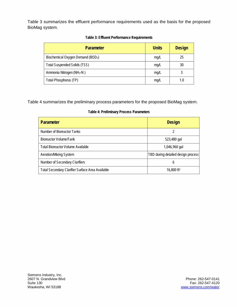
Siemens Industry, Inc. 2607 N. Grandview Blvd Phone: 262-547-0141 Suite 130 Fax: 262-547-4120 Waukesha, WI 53188 www.siemens.com/water
Table 3 summarizes the effluent performance requirements used as the basis for the proposed BioMag system.
Table 3: Effluent Performance Requirements
Parameter Units Design
Biochemical Oxygen Demand (BOD5) mg/L 25
Total Suspended Solids (TSS) mg/L 30
Ammonia Nitrogen (NH3-N ) mg/L 3
Total Phosphorus (TP) mg/L 1.0
Table 4 summarizes the preliminary process parameters for the proposed BioMag system.
Table 4: Preliminary Process Parameters
Parameter Design
Number of Bioreactor Tanks 2
Bioreactor Volume/Tank 523,480 gal
Total Bioreactor Volume Available 1,046,960 gal
Aeration/Mixing System TBD during detailed design process
Number of Secondary Clarifiers 6
Total Secondary Clarifier Surface Area Available 16,800 ft2

Siemens Industry, Inc. 2607 N. Grandview Blvd Phone: 262-547-0141 Suite 130 Fax: 262-547-4120 Waukesha, WI 53188 www.siemens.com/water
5 BIOMAG SYSTEM COMPONENTS
5.1 Ballast Feed System
A 25-ton silo is used for onsite storage of magnetite to allow for periodic bulk delivery. Figure 2 below is an example of what a typical storage silo for ballast feed.
Figure 2: Example Magnetite Storage Silo
Virgin magnetite is feed from the storage silo to the ballast mix tank using a pneumatic conveyance system consisting of a Transflow® Stinger assembly as shown in Figure 3 below. The Stinger is flange mounted to the bottom of the silo and connected to a compressed air source.
Figure 3: Transflow® Stinger Assembly
5.2 Biosolids Wasting
For optimal process performance and ballast recovery, Siemens recommends the following wasting capabilities be implemented with the BioMag system: (1) surface waste using a classifying selector in addition to wasting via slip stream RAS, (2) wasting to a single holding tank/thickener prior to ballast recovery. This type of wasting capability is preferable for the following reasons:

Siemens Industry, Inc. 2607 N. Grandview Blvd Phone: 262-547-0141 Suite 130 Fax: 262-547-4120 Waukesha, WI 53188 www.siemens.com/water
• Classifying selectors (coupled with baffle designs that do not trap foam) are used to eliminate the population of foam-causing organisms in activated-sludge plants to prevent the development of nuisance foams. The term, classifying selector, refers to a physical mechanism by which these organisms are selected against; foam-causing organisms float to the surface and their rapid removal controls their population at low levels in the mixed liquor. Foam-causing organisms are wasted “first” rather than accumulating on the surface of tanks and thereby being wasted “last”. Details about the classifying selector will be developed during the detailed design.
• The integrity of the biological floc is disrupted in the holding tank/thickener, rendering it more amenable to magnetite separation and recovery from the floc. Polymer is biodegraded and the floc becomes more dispersed and fragile, thereby increasing the recovery efficiency and maximizing the capacity of the recovery system.
• The holding tank/thickener provides a wide spot in the WAS processing line, allowing the magnetite recovery system to be operated intermittently, if desired. This allows the operators to waste continually from the clarifiers, with the flexibility to run the recovery system intermittently, or vice versa.
• With a holding tank/thickener, the operators are able to periodically waste at elevated rates, should it become necessary, without overloading the recovery system.
The following summarizes the essential features recommended for the classifying selectors:
• A baffle will be placed on the surface of the mixed liquor channel that will direct foam to a hinged weir on the side of the tank. Continuous surface overflow of the mixed liquor over a weir and into a sump, thereby wasting the foam-formers faster than they can grow.
• Continuous or nearly continuous pumping of the wasted material from the sump to a holding tank/thickener.
5.3 Ballast Recovery System
From the thickening tank(s), the ballasted WAS is pumped to the ballast recovery system. The main components of the ballast recovery system are as described below.
5.3.1 Magnetic Drum Separator
Magnetite is recovered from the waste sludge using a magnetic drum separator (Figure 4). Ballasted waste sludge is fed to the drum through an overflow weir that promotes contact of the sludge to the drum. The sludge then flows down through the drum sump where magnetic forces created by a stationary array of magnets located behind the rotating drum attract the magnetite to the drum. The drum rotates in the opposite direction of sludge flow and lifts magnetite up out of the sump to be scraped off for re-use in the ballast mix tank.

Siemens Industry, Inc. 2607 N. Grandview Blvd Phone: 262-547-0141 Suite 130 Fax: 262-547-4120 Waukesha, WI 53188 www.siemens.com/water
Figure 4: Typical Magnetic Drum Separator
5.3.2 Shear Mill
Prior to recovery with the magnetic drum separator the waste sludge must first be conditioned to enhance separation of the magnetite from the floc. A mechanical inline shear mill is used to perform this conditioning step.
5.3.3 Fine Screening
Trash and non-biodegradable solids, such as hair, lint, grit and plastics can reduce the efficiency of magnetite recovery if allowed into the system. This design assumes that the existing primary clarifiers will be adequate to treat the additional load proposed and that the primary clarifiers will continued to be used along with the BioMag system. Therefore the BioMag system will not require a fine screen system to be installed as part of the ballast recovery system.
5.4 BioMag Control System
The BioMag control system provides automatic control of the ballast feed and recovery processes to keep the BioMag process operating efficiently, regardless of varying conditions. Designed by our biological treatment experts, the software of the BioMag control system encodes Siemens unique process knowledge to ensure system performance. Providing continual feed back and archiving process information the system provides the operator with easy-to-use tools for the most efficient plant control. The BioMag control system features PLC based controls with a panel PC that utilizes a graphical interface (Figure 5). The system can interact with existing SCADA systems or be included in a comprehensive new SCADA system for the entire plant.

Siemens Industry, Inc. 2607 N. Grandview Blvd Phone: 262-547-0141 Suite 130 Fax: 262-547-4120 Waukesha, WI 53188 www.siemens.com/water
Figure 5: BioMag Control Panel
6 SCOPE OF SUPPLY
The scope of supply for the proposed BioMag system is summarized in the attached design and scope summary document.
7 SUPPORT SERVICES
Siemens can provide the following supports services for the BioMag system
Services
Engineering support
Review of design and bid documents Participation in design meetings Submission of sketches, plans and other design phase
documentation Shop drawings for the BioMag equipment within Siemens
scope.
Installation Oversight, Commissioning & Training
Services of a representative for up to 11, 8 hour days Recommend necessary adjustments and test equipment. Verify proper installation of the BioMag and ancillary systems
prior to startup.
Start-up & Performance Testing
Services of a representative for up to 15, 8 hour days for Start-up & performance testing
During this period Siemens will confirm that the system operates in accordance with the performance test requirements under the specified operating conditions.

Siemens Industry, Inc. 2607 N. Grandview Blvd Phone: 262-547-0141 Suite 130 Fax: 262-547-4120 Waukesha, WI 53188 www.siemens.com/water
8 BUDGETARY PRICING
The budgetary price for the Siemens BioMag system, as defined herein, including process and design engineering, field services, and equipment supply is $2,442,000.
The scope of supply and pricing are based on Siemens standard equipment selection, standard terms of sale and warranty terms as described herein. Any variations from these standards may affect this budgetary quotation. Additionally, please note this budgetary quotation is for review and informational purposes only and does not constitute an offer for acceptance.
This price makes no provision for taxes, tariffs, duties, permitting fees and other fees and charges that are not made explicit above.
All pricing is quoted at FOB, Factory (full freight allowed). No taxes, regulatory fees or other costs related to the procurement and installation of the system are included.

Siemens Industry, Inc. 2607 N. Grandview Blvd Phone: 262-547-0141 Suite 130 Fax: 262-547-4120 Waukesha, WI 53188 www.siemens.com/water
Appendices
A. Frequently Asked Questions

Siemens Industry, Inc. 2607 N. Grandview Blvd Phone: 262-547-0141 Suite 130 Fax: 262-547-4120 Waukesha, WI 53188 www.siemens.com/water
APPENDIX A – FREQUENTLY ASKED QUESTIONS
1. GENERAL QUESTIONS ABOUT MAGNETITE, THE FUNDAMENTAL ELEMENT USED IN BIOMAG TO INCREASE SETTLING RATES AND RELIABILITY.
Q What is magnetite?
A Magnetite is fully oxidized iron ore (Fe3O4). It is completely inert; it cannot rust; it doesn’t degrade with time or usage; it has no effect on biological floc; and it is not magnetic itself, i.e., it doesn’t stick to metal. If you have ever played with an “Etch-a-Sketch,” the material inside the toy is magnetite.
Q How does magnetite improve the performance of clarifiers and biological treatment systems?
A Magnetite is a very dense material with a specific gravity of 5.2. By comparison, the specific gravity of water is 1.0; a chemical hydroxide floc is fractionally over 1.0; and a biological floc is ~1.25. By infusing magnetite into either a chemical or biological floc, the specific gravity is increased by 50 to 100%, thereby significantly increasing the settling rate of the floc and gaining consistent control of the sludge blanket in the clarifier and greater stability for the whole system.
Q Is magnetite readily available?
A Yes, magnetite is mined and processed at multiple sites around the world. In the USA, Siemens has identified multiple vendors that will provide magnetite to our specifications.
Q What is the cost of magnetite?
A Magnetite is very inexpensive, ranging from $0.20 to $0.50 per pound delivered, depending on the location of the distributor and the facility. Moreover, since the recovery rates of magnetite in BioMag systems are so high, daily consumption is very low. In fact, while evaluating the operating cost of a BioMag system, the ongoing cost of magnetite is negligible.
Q Is the magnetite abrasive? Does magnetite cause excessive wear to pumps?
A Unlike micro-sand, the ballast used by a competing technology, Siemens specified magnetite is so fine that it has the consistency of talcum powder; hence, it is not abrasive and doesn’t cause abnormal wear and tear on a treatment system pumps, mixers, valves and other components.
Q Does magnetite degrade at high temperatures (or low temperatures) or with changes in pH?
A Magnetite does not undergo any physical or chemical changes at the temperature and pH ranges associated with almost all municipal and industrial wastewater treatment.

Siemens Industry, Inc. 2607 N. Grandview Blvd Phone: 262-547-0141 Suite 130 Fax: 262-547-4120 Waukesha, WI 53188 www.siemens.com/water
Q Does magnetite affect pH or the chemical characteristics of the effluent?
A No, magnetite is completely inert. It has no effect on pH or the chemical characteristics of a system’s effluent.
Q Does magnetite affect the oxygen content of wastewater?
A Since magnetite (Fe3O4,) is fully oxidized, it does not consume dissolved oxygen in wastewater being treated.
Q How much magnetite is recovered on the magnetic drum and where does the remainder go?
A Siemens has modified the design of conventional magnetic drums to optimize the capture and reuse of magnetite. In BioMag systems, the capture reuse rate is more than 96%. Any magnetite not captured by the drum is carried away in the sludge where we have found no effect on downstream sludge management systems or processing.
Q How does magnetite in the effluent effect the performance of a downstream UV disinfection system?
A Since very little of the magnetite escapes the system, the direct effect is not discernable.
2. QUESTIONS ABOUT BIOMAG AND THE USE OF MAGNETITE IN BIOLOGICAL PROCESSES.
Q To what types of biological treatment systems can BioMag be applied?
A BioMag is most effective in enhancing the capacity and/or nutrient removal performance of activated sludge systems, including oxidation ditch, conventional air, extended air, HPO, and SBR based systems.
Q Does BioMag work with HPO?
A Yes, Siemens has successfully tested the ability of BioMag to infuse and recapture magnetite from the relatively small and weak HPO biological floc. Hence, we are confident that magnetite can be effectively used to ballast mixed liquor from HPO facilities.
Q What is the optimum MLSS concentration for various activated sludge applications: conventional, extended air, SBR, oxidation ditches etc.
A There is no simple answer to this question as the MLSS concentration targets depend on plant objectives for capacity and nutrient removal, the type of activated sludge technology employed, economic practicality and how the above are expected to change over time. With this said, Siemens has achieved excellent results with MLSS ranging from 5,000 to 12,000mg/L.

Siemens Industry, Inc. 2607 N. Grandview Blvd Phone: 262-547-0141 Suite 130 Fax: 262-547-4120 Waukesha, WI 53188 www.siemens.com/water
Q What is the optimum ratio of magnetite to MLSS in a BioMag enhanced system?
A We typically design for 1:1 ratio and optimize the system during commissioning to meet a project’s specific need. Note that the amount of magnetite in the system can be varied as needed to control the blanket in the secondary clarifier; for example, a ratio of 1.2 magnetite to MLSS would be desirable to manage high wet weather flows passing through the biological treatment system.
Q How much magnetite is maintained in a typical activated sludge system enhanced by BioMag?
A This depends on the size of the system and the density of the mixed liquor. But consider a 1,000,000 gallon bioreactor enhanced with BioMag technology. Assume the system is running 8,000 mg/L MLSS ballasted with 8,000 mg/L of magnetite (a 1:1 ratio). The weight of the water is ~8.34million pounds; the weight of the MLSS is ~67,000 pounds as is the magnetite. Note the magnetite increases the mass of the system by ~ 0.8%. While this is sufficient to manage the settling of the blanket, it is a very small addition to the overall mass of the system.
Q Keeping an MLSS of 10,000 mg/L that is infused with 10,000 mg/L of magnetite must create challenges in keeping the resulting 20,000 mg/L of solids suspended in the bioreactor. How does Siemens solve this problem?
A Much depends on an assessment of the existing or proposed aeration system and the objectives of incorporating BioMag. An increase in MLSS density for the purpose of increasing treatment capacity will necessarily require increased aeration for purposes of oxygen transfer to a larger biomass, a byproduct of which is increased mixing energy. Additional mechanical mixing may also be necessary to maintain full suspension especially if anoxic zones are incorporated. Consideration also has to be given to the type of aeration equipment: course bubble diffusers often provide sufficient mixing energy to keep the magnetite and MLSS in suspension while fine bubble diffusion usually requires additional mechanical mixing.
Q What types of mixing systems are best suited to achieve the mixing required to impregnate biological floc with magnetite and to keep the floc in suspension?
A Mixing can be achieved with mechanical mixers, diffused air, jet mixers/aerators, or a combination thereof. Anoxic and anaerobic zones are typically mixed with either submerged or floating mechanical mixers. Aerobic zones are normally mixed with either coarse bubble, jet aeration or a combination of fine bubble and mechanical mixing.
Q How much mixing energy is required to maintain magnetite infused biological floc in suspension?

Siemens Industry, Inc. 2607 N. Grandview Blvd Phone: 262-547-0141 Suite 130 Fax: 262-547-4120 Waukesha, WI 53188 www.siemens.com/water
A The mixing equipment for magnetite ballasted systems is designed to ensure suspension of the particles from a cold start which equates to an installed power requirement of approximately 55HP per million gallons of tankage.
Q Does magnetite addition suppress or exacerbate foaming in an activate sludge process?
A Foaming is a function of the operation of the biological treatment system. The inert characteristics of magnetite neither enhances or diminishes the production of foam.
Q What effect does magnetite have on the density for the sludge at the bottom of the secondary clarifier?
A Magnetite infused in the biological floc increases the thickening of the sludge blanket to ~ 2% solid.
Q With magnetite increasing the density of the sludge blanket at the bottom of the clarifier, can the RAS flow and the cost of pumping be reduced?
A It depends on the application. If magnetite is added to a system to improve only settling, and average forward flow and MLSS is not increased, there will be an increase in RAS concentration and RAS flow can be decreased accordingly. In typical BioMag applications, however, magnetite is added to enable an increase in MLSS to handle additional flow/loading or increased treatment; these applications will require AN increase in RAS flow commensurate with the increase in flow.
Q What is the effect of the magnetite to the WAS flow?
A. The very same effect as described in the above description of the effect of magnetite on RAS flow.
Q What is defined as well mixed? What mixing tests are performed and how are they measured?
A Well mixed is defined by TSS testing at various depths and locations throughout the bioreactor to maintain MLSS concentrations at ±15%.
Q Can coagulants be added to a BioMag enhanced activated sludge system? Does one type of coagulant work better than others?
A The addition of coagulants to the BioMag system results in precipitation of phosphorus and a higher quality effluent. Extensive testing has been carried out proving that BioMag works equally well with all common coagulants. The selection of coagulant type is typically dependant on client preference.
Q What happens to ortho phosphates?
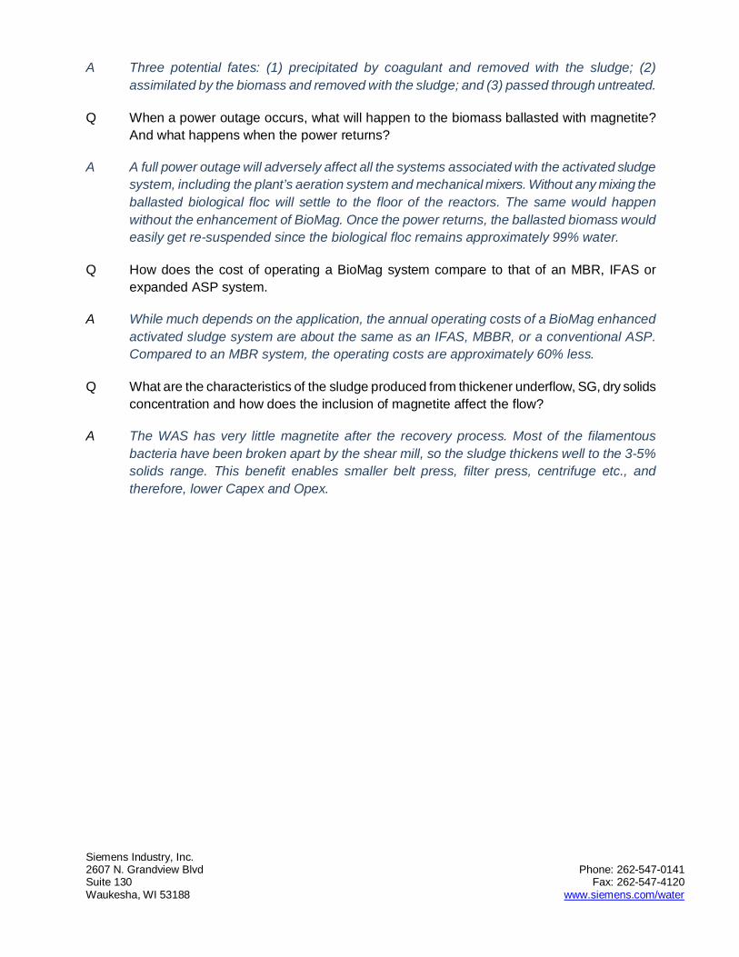
Siemens Industry, Inc. 2607 N. Grandview Blvd Phone: 262-547-0141 Suite 130 Fax: 262-547-4120 Waukesha, WI 53188 www.siemens.com/water
A Three potential fates: (1) precipitated by coagulant and removed with the sludge; (2) assimilated by the biomass and removed with the sludge; and (3) passed through untreated.
Q When a power outage occurs, what will happen to the biomass ballasted with magnetite? And what happens when the power returns?
A A full power outage will adversely affect all the systems associated with the activated sludge system, including the plant’s aeration system and mechanical mixers. Without any mixing the ballasted biological floc will settle to the floor of the reactors. The same would happen without the enhancement of BioMag. Once the power returns, the ballasted biomass would easily get re-suspended since the biological floc remains approximately 99% water.
Q How does the cost of operating a BioMag system compare to that of an MBR, IFAS or expanded ASP system.
A While much depends on the application, the annual operating costs of a BioMag enhanced activated sludge system are about the same as an IFAS, MBBR, or a conventional ASP. Compared to an MBR system, the operating costs are approximately 60% less.
Q What are the characteristics of the sludge produced from thickener underflow, SG, dry solids concentration and how does the inclusion of magnetite affect the flow?
A The WAS has very little magnetite after the recovery process. Most of the filamentous bacteria have been broken apart by the shear mill, so the sludge thickens well to the 3-5% solids range. This benefit enables smaller belt press, filter press, centrifuge etc., and therefore, lower Capex and Opex.

Industry, Inc.
Project: Oak Orchard WPCP Date: 06/06/2013Engineer: GHD Designer: Avinash Bhat
ADF 9.00 MGDMMF 9.00 MGDPWF 9.00 MGDPDF 24.00 MGDPHF 24.00 MGDBOD5 168 mg/L 12,610 lb/day BOD5 25 mg/L 1,877 lb/dayTSS 80 mg/L 6,005 lb/day TSS 30 mg/L 2,252 lb/dayNH3-N — mg/L — lb/day NH3-N 3 mg/L 225 lb/dayNO3-N — mg/L — lb/day NO3-N — mg/L — lb/dayTKN 28 mg/L 2,068 lb/day TKN 4 mg/L 300 lb/dayTotal P 4 mg/L 293 lb/day Total P 1 mg/L 75 lb/dayTN 28 mg/L 2,068 lb/day TN — mg/L — lb/day
SRT for Nitrification 7 days Total System SRT 7 daysDesign MLSS Liquid Temp 20.0 °CMin MLSS Liquid Temp 10.0 °COrganic Loading Rate 90.1 lb/1,000 ft³/daySystem Organic Loading Rate 90.1 lb/1,000 ft³/dayMLSS 7,700 mg/LSludge Yield 0.73Total WAS 9,163 lb/day
Installed Power
Quantity Connected
Quantity Operating
2 11 11 11 13 33 31 11 10 0.00
Total
Influent Design Conditions
Effluent Design Conditions
Ballast Tank Discharge Pumps 10
Component
Operating Power
Hp
Ballast Tank Mixer
10
Mag Drum Separator 7
BioMag Design Conditions
3
Shear Mill 50
WAS Pumps to Shear Mill/Mag Drum 10
BioMag™ Design Summary
110
Total Connected Hp
40310102115010
244
Mag Distribution Compressor 20
Chemical PumpsPolymer Feed WAS Pumps From Mag Drum
Private & Confidential

Industry, Inc.
Equipment List
ScopeSiemensBy OthersSiemensSiemensSiemensSiemensBy Others
ScopeSiemensSiemensSiemensSiemensSiemensSiemens
ScopeSiemens Secondary Clarifier Sludge Blanket SensorsSiemensSiemensSiemensSiemensBy Others
ScopeSiemens 2 trips 6 days total of mechanical field servicesSiemens 2 trips 8 days total of electrical / I&C field servicesSiemens 3 trips 12 days total of process field services
Excluded Items
— Polymer Dosing System
• Utilities connections.
• Tools or spare parts.• Unloading of equipment and protected storage of equipment at jobsite.
• Detail shop fabrication drawings.
Services
Qty Description111
General Items• Compliance permitting and approval (Federal, State and/or local).
111 Software and Graphics package
• Electrical, hydraulic, or pneumatic controls unless specifically noted.• Engineering and supervision of all equipment and labor for civil works.• Laboratory, shop, or field testing other than supervision of start-up testing.• Taxes, bonds, fees, permits, lien waivers, licenses, etc.
—
Programable Logic Controller (PLC)Control Panel with Operator Interface Module
MCC or MCC Buckets, Starters, VFDs, Wiring, etc.
1 (1) duty (0) standby 10Hp Recovery System Discharge Pump(s)1 (1) duty (0) standby 10Hp Recovery System Feed Pump(s)
1 4 in. flowmeter for ballast tank feed control1 4 in. 120V single ph. auto. plug valve for ballast tank feed control
1 (1) duty (0) standby 10Hp Ballast Tank Discharge Pump(s)
3 2.5 in. flowmeter(s) for Mag Recovery Drum feed control3
3 (3) duty, (0) standby model 36x72 Magnetite Recovery Drum(s)3
Magnetite Feed System
Qty Description25 ton Outdoor Silo
1 1200 gallon ballast mix tank (5.5 ft x 5.5 ft x 5.5 ft swd)
(3) duty, (0) standby 50 Hp Shear Mill(s)
Magnetite Recovery System
Qty Description
1
1 (1) duty (0) standby 3Hp Ballast Tank Mixer(s)
2.5 in. 120V single ph. auto. plug valves for Mag Recovery Drum screen feed control
6
Instrumentation & Controls
Qty Description
1 TSS probes total. (1) in basin (0) inline
Private & Confidential

Industry, Inc.
• Pipe supports and hangers for piping.• Piping, pumps, valves, wall sleeves, gates, drains, weirs, baffles not mentioned.• Plumbing associated with waste disposal, floor drains, and/or emergency and safety wash stations.• PVC solvent weld materials.
Electrical Items• Conduit or wiring in the field.
• Installation of equipment.• Interconnecting materials external to enclosures such as cable, pressure taps, tubing, etc.
Process Items
Civil Works and Mechanical Items• Adhesives, adhesive dispensers, grout, mastic & anti-seize compounds.• Anchor bolts and/or expansion anchors unless otherwise noted.
• Labor for field testing.• Lubricants, grease piping, grease guns.• Modifications to existing equipment or structures.
• Base slabs, equipment mounting pads, or shims.• Concrete work of any sort, grout, mastic, sealing compounds, shims.• Demolition, removal, or transfer of anything that is existing.• Engineering, permitting, and surveying.• Equipment lifting hoists, cranes, or other lifting devices.
• Motor control centers.
• Cable trays, fittings, and supports.
• Variable frequency drives unless specifically noted.
• Plant lighting.• Supply and installation of building power, lighting, main service disconnects and control panels.• Supply, installation and control of SCADA to monitor/control overall plant• Underwriters Laboratory inspection of electrical controls.
• Influent instrumentation including, but not limited to flowmeters, pH analyzers, temperature • Instrumentation required for post treatment monitoring.• Power to Siemens supplied equipment.
• Field surface preparation and/or painting.• Floor grating, stairways, ladders, platforms, handrailing unless noted.
• Bioreactor aeration blowers.• Bioreactor instruments, valves or pumps.• Bioreactor aerators.
Private & Confidential

Appendix B – MBBR Pretreatment Vendor Information
GHD | Oak Orchard Wastewater Treatment Plant Capacity Expansion Evaluation, Onondaga County, NY 8615142.2

Biowater Technology US LLC
2155 Diamond Hill Road
Suite 2, Mailbox 4
Cumberland, RI 02864
Ph: +1 401-305-3622
Fax: +1-305-3677 +1 401-305-3677 +1 401-305-3677
June 21, 2013
Re: Biowater Conceptual Design and Budget Estimates (Oak Orchards, NY), CRM# 516 Dear Jason, Biowater Technology provides this preliminary feedback related to retrofit of the Oak Orchards, NY WWTP. We have provided two options below that will increase the current treatment capacity of the plant by approximately 30% and allow seasonal nitrification. The proposed process involves use of Biowater’s complete mix fixed film (CMFF®) as a roughing reactor in front of high purity oxygen (HPO) activated sludge. For both options, RAS will be introduced after the CMFF® basins.
It is not technically feasible to leave the existing HPO aeration basins as is and retrofit the secondary flocculation tank to fixed film basins, which would function as a combined fixed film and activated sludge (CFAS® or IFAS) system, with sludge from the final settling tanks being returned to the front of the HPO tanks. There are both hydraulic and nitrification limitations for that option.
I. Proposed Biofilm Process
Option 1: Convert the first section of the HPO basins into fixed film basins and leave the remaining basins in each train as HPO basins. This option would require partial removal of the concrete deck above the 1st HPO basin, removal of the mechanical surface aerators on that 1st stage, installation of Biowater’s engineered diffused aeration system, and addition of biofilm carrier retention sieves and carriers.
Option 2: Install new CMFF® basins after the primary settling tanks and before the existing HPO tanks.
Mr. Jason Green, PE GHD 1 Remington Park Drive Cazenovia, NY 13035 Via Email : [email protected]

II. Biological Design Considerations
Parameter Primary Effluent Secondary Effluent
Design Flow 13 MGD
BOD5 149 mg/L (16,165 lb/d) <30 mg/L
NH4-N 21 mg/L (2,277 lb/d) <400 lb/d (June-Oct)
<3.7 mg/L @ design flow
TKN 26 mg/L (2,819 lb/d)
TP 4.25 mg/L ( 461 lb/d) <1 mg/L
TSS 71.5 mg/L (7,752 lb/d) <20 mg/L
Design WW Temp. 10° C Winter, 18° C Summer
Site Elevation 600 ft. AMSL
III. Summary of Biological Design Criteria
Design Parameter Option 1 (Retrofit 1st 1/3 of HPO Tanks)
CMFF®
Option 2 (Construct New Tanks)
CMFF®
Number of Process Trains 2 2
Number of Aerobic Basins in Series
1 1
Biofilm Carrier Type BWT-X BWT-X
Biofilm Specific Surface Area, m
2/m
3
650 650
Design Side Water Depth, ft. 9 15
Recommended Freeboard, ft. 2 2
Reactor Length, ft. 36 40
Reactor Width, ft. 72 40
Required fixed film surface area, m
2
294,450 294,450
Alkalinity Requirements 12,691 lb/d 12,691 lb/d
Blower Airflow Requirements 6,013 scfm @ 4.96 psig discharge pressure
(170 bhp)
3,100 scfm @ 7.56 psig discharge pressure
(127 bhp)
Budgetary Estimate,
FOB Factory with Freight Allowed
$792,000 $713,600

IV. Proposed Scope of Supply
Biofilm carriers will be provided with specific surface area and total fixed film area given above, specific to design criteria as stated above.
A complete site specific, engineered diffused aeration system will be provided in 304L stainless steel including header and lateral piping for each aerobic reactor. All supports for the aeration grid systems, manifolds and drop pipes internal to the basins will be supplied. The termination point for the aeration system drop pipe will be a flanged connection at the tank wall height. Materials of construction are schedule 5 and Schedule 10 304L Stainless Steel piping. All flanges will be 150 lb. ANSI style.
Biofilm carrier retention sieve assemblies will be provided for each reactor containing biofilm carriers. Sieve assemblies will be designed at a peak instantaneous flow plus recycle streams, when applicable. Sieve assemblies will be fitted with 150-lb ANSI flanges, and will be of 304L stainless steel construction.
Process Engineering consisting of aeration system sizing and configuration, sieve and outlet design. Review and approval of P&I Diagram for the biological treatment process. Preliminary General Arrangement Drawings and review and approval of final General Arrangement Drawings for the biological treatment process. Review of biological process drawings with respect to nozzles, penetrations and dimensions, excluding structural design. Functional specification for pumps, blowers, instrumentation, and control equipment related to the biological treatment process. These are all included herein.
On-site startup support, submittals and operations and maintenance manuals are budgeted herein.
V. Notes and clarifications
Basins for housing the fixed-film process internals will be required and are not included herein.
Controls and instrumentation, specifically DO sensors will be required for process control and are not included herein.
Blowers will be required to supply the reactors with airflows given above, at least one operational and one stand-by, and are not included herein.
Dosing pumps (alkalinity) may be required and are not included herein.
Unloading, storage and installation of equipment are the responsibility of the client. All civil/site, rigging, electrical work, interconnecting piping, and startup to be provided by client or others appointed or hired by the client.
Duties and taxes are not included herein.
Subject to Biowater Technology’s standard terms and conditions.
This estimate is budgetary and subject to change. Firm pricing can be provided upon request. We look forward to working with you on this project. Please feel free to contact us at 401-305-3622 or via email at [email protected] if you have any questions or concerns.
Best regards,
Joshua Hanlon
Sales Director

Appendix C – IFAS Post-Treatment Vendor Information
GHD | Oak Orchard Wastewater Treatment Plant Capacity Expansion Evaluation, Onondaga County, NY 8615142.2

Kruger Inc. 4001 Weston Parkway Cary, NC 27513 USA Tel: 919-677-8310 ● Fax: 919-677-0082 Web site: www.krugerusa.com
June 21, 2013 Jason Greene GHD 1 Remington Park Drive Cazenovia, NY 13035
Re: AnoxKaldnes™ Hybas™ Proposal
Oak Orchard, NY Kruger Project No: 5700132314 Dear Mr. Greene: Enclosed is our AnoxKaldnes Hybas (Hybrid Biofilm Activated Sludge) proposal for the Oak Orchard WWTP. This design is based on data provided to us by you. As detailed herein, we propose retrofitting the existing post aeration flocculation basin into two (2) parallel IFAS Trains, each train comprised of one (1) aerobic Hybas reactors for biological treatment of BOD and NH3
-N. No modifications are proposed for the HPO trains in our proposal but the aeration system should be able to meet the AORs shown in the design summary after applying an appropriate peaking factor for peak day loading.
The treatment capacity of the HPO system incorporating the HYBAS reactors is 13 MGD. The following design assumptions apply to this design proposal
1. The maximum month primary effluent mass loading
rates to the HPO system are:
a. BOD:- 12,260 lbs/day (140 mg/L @ 10.5 MGD) b. TSS – 6,130 lbs/day (70 mg/ @ 10.5 MGD) c. TKN – 2,000 lbs/day (23 mg/L @ 10.5 MGD)
2. The total forward flow through the IFAS reactors is limited to 8.5 MGD (influent + RAS).
Excess flow above that amount is bypassed around the reactors and recombined with the HPO reactor flow prior to secondary clarification.
3. The secondary clarification capacity, whether or not new clarifiers or tertiary filtration are required, must produce a maximum month effluent TSS < 15 mg/L to ensure the secondary effluent BOD remains below 10 mg/L. The effluent BOD of 10 mg/L is required to ensure compliance with the UOD mass limit of 4,280 lbs/day.
For the aerobic Hybas reactors, Kruger suggests using our AnoxKaldnes Medium Bubble Aeration System. Normally AnoxKaldnes aeration equipment achieves a 1-1.1% SOTE. Sufficient air should be provided to keep the media well mixed and in suspension. As an added safety, the design includes an air scour system to aid in purging media away from the sieves. The system consists of a set of small air diffusers located just below the top row of sieves in the HYBAS zone which are connected to a small regenerative blower station. Thank you for your interest in the AnoxKaldnes Hybas process; we appreciate the opportunity to provide this proposal to you. If you have any questions or need further information, please

Kruger Inc. 4001 Weston Parkway Cary, NC 27513 USA Tel: 919-677-8310 ● Fax: 919-677-0082 Web site: www.krugerusa.com
contact our local representative, Mark Koester of Koester and Associates, or our Regional Sales Engineer, Ken Krupa (540-389-5092) ; [email protected]). Respectfully, I. Kruger Inc. Sent via email Brad Mrdjenovich Applications Engineer ATT cc: CT, LGW, KMK project file (Kruger) Mark Koester (Koester and Associates)

AnoxKaldnes™ Hybas™ Proposal for
Oak Orchard, NY
Kruger Project No.: 5700132314
Jason Greene GHD 1 Remington Park Drive Cazenovia, NY 13035 April 29, 2013 June 21, 2013 I. Kruger Inc. 4001 Weston Parkway Cary, NC 27513

Table of Contents
1. Company Introduction
2. Energy Focus
3. Process Description
4. Design Summary
5. Scope of Supply
6. Design Options
7. Pricing, Terms of Payment, and Schedule
8. I. Kruger Inc. Standard Terms of Sale
The information or data contained in this proposal is proprietary to Kruger and should not be copied, reproduced, duplicated, or disclosed to any third party, in whole or part, without the prior written consent of Kruger. This restriction will not apply to any information or data that is available to the public generally.
Proposal History
Revision Date Process Eng. Comments
0 04/29/2013 LGW Initial, budgetary proposal.

1
1. Company Introduction I. Kruger Inc. (Kruger) is a water and wastewater solutions provider specializing in advanced and differentiating technologies. Kruger provides complete processes and systems ranging from biological nutrient removal to mobile surface water treatment. The ACTIFLO® Microsand Ballasted Clarifier, BIOCON® Dryer, BIOSTYR® Biological Aerated Filter (BAF), AnoxKaldnes Hybas, AnoxKaldnes™ MBBR, NEOSEP™ MBR and HYDROTECH Discfilters are just a few of the innovative technologies offered by Kruger. Kruger is a subsidiary of Veolia Water Solutions and Technologies (VWS), a world leader in engineering and technological solutions in water treatment for industrial companies and municipal authorities. VWS, present throughout the world, develops a global approach responding to specific needs of customers at each of their production facilities. This has allowed VWS to become the world leader in design, project management, and execution of projects for water and wastewater treatment plants. The company also creates dedicated technology solutions to meet its customer’s needs. Its unique portfolio of differentiating technologies, developed by the group’s R&D centers, ensures unsurpassed innovation and control of each treatment line for public organizations and industries. Furthermore, a whole range of associated services is offered on each site to guarantee the technical efficiency and life expectancy of the installed solutions. VWS continually extends and enriches its offer, to guarantee expertise and competence at every step of the projects it undertakes. Kruger prides itself for being a customer focused organization that provides solutions to challenges faced by municipalities and not just another equipment supplier. To achieve this, Kruger has gathered a force of process experts, trained sales staff, and project managers that share our vision and priorities. 2. Energy Focus
Kruger, along with Veolia Water Solutions & Technologies (VWS) is dedicated to delivering sustainable and innovative technologies and solutions.
We offer our customers integrated solutions which include resource-efficient technology to improve operations, reduce costs, achieve sustainability goals, decrease dependency on limited resources, and comply with current and anticipated regulations.
Veolia’s investments in R&D outpace that of our competition. Our focus is on delivering
neutral or positive energy solutions
migration towards green chemicals or zero chemical consumption
water-footprint-efficient technologies with high recovery rates
Our carbon footprint reduction program drives innovation, accelerates adoption and development of clean technologies, and offers our customers sustainable solutions.
Kruger is benchmarking its technologies and solutions by working with our customers and performing total carbon cost analysis over the lifetime of the installation.
By committing to the innovative development of clean and sustainable technologies and solutions worldwide, Kruger and VWS will continue to maximize the financial benefits for every customer.

2
3. Process Description
Kruger’s AnoxKaldnes process design is based on more than 20 years of experience with Moving Bed Biological Reactors (MBBR) and Integrated Fixed Film Activated Sludge (IFAS) systems. Our knowledge is supported by lab and pilot scale studies and data from more than 475 AnoxKaldnes operating systems for BOD, nitrification, and TN removal. The MBBR and IFAS (or Hybas - Hybrid Biofilm Activated Sludge) processes are continuous flow through, non-clogging bio-film reactors containing “carrier elements” or media with a high specific surface. The media does not require backwashing or cleaning. The biomass that treats the wastewater is attached to the surfaces of the media. The media is designed to provide a large protected surface area for the biofilm and optimal conditions for biological activity when suspended in water. Media of different shapes and sizes provide flexibility to use the most suitable type depending on wastewater characteristics, discharge standards and available volumes. AnoxKaldnes media is made from polyethylene and has a density slightly less then water. In the MBBR process, all of the biomass is attached to the media and retained in the reactor, with no returned sludge. In the Hybas process, the reactor contains both free-floating biomass (activated sludge) and biomass attached to the media. The free-floating biomass passes through the reactor, is settled and recycled back to the reactor. The media and attached biofilm remain in the reactor as in a MBBR.
AnoxKaldnes Hybas Nitrification System
The Hybas process is often considered for upgrading existing conventional activated sludge systems within the existing tankage for either maintaining nitrification at new higher flow rates or loads or upgrading a plant to meet new nitrification requirements. It is accomplished by adding the media directly into the activated sludge reactors to enhance the growth of the autotrophic bacteria. The Hybas system is capable of meeting these new effluent requirements at low solids retention times (SRTs) and short hydraulic retention times (HRTs). The mixing of the media within MBBR and Hybas reactors is provided by AnoxKaldnes’ medium bubble aeration system in aerobic application, whereas specially designed submersible mixers are used in anoxic environments for denitrification.

3
AnoxKaldnes Medium Bubble Air Grid
The media is retained within the reactor using stainless steel retention screens.
AnoxKaldnes Stainless Steel Cylindrical Screen
Kruger’s minimum scope of supply for MBBR and Hybas systems includes the AnoxKaldnes media, screen assemblies (to keep media in each reactor), medium bubble aeration grid assemblies and submersible mixers for the anoxic zones. In cases where they are needed, Kruger also provides the blowers, instrumentation and controls, SCADA, and field instruments (dissolved oxygen, nitrate, ammonia, etc.) for single source responsibility. 4. Design Summary The proposed design is based on the following influent wastewater characteristics and incorporating peak flow conditions for screen design purposes only. The design assumes that the raw influent wastewater is biodegradable, no toxic compounds are present, sufficient alkalinity is available to avoid pH depressions, that the COD/BOD ratio is between 1.7 and 2.3,

4
and that none of the equipment provided would be used in a classified area (e.g. Class 1, Division 1 or Class 1, Division 2). Facilities with primary clarification will require screening with a maximum of 6 mm (1/4 inch) openings for removal of particulate matter (rags, debris, etc.) prior to entering the AnoxKaldnes treatment reactors. Facilities that lack primary clarification will require screening with a maximum of 3 mm (1/8 inch) openings. The Hybas system influent design basis is summarized in Table 1. The target effluent criteria for the system are listed in Table 2. The process design is summarized in Table 3.
Table 1: AnoxKaldnes HPO/Hybas Influent Design Basis (Primary Effluent)
Parameter Units Value
Flow, Maximum Month1 MGD 10.5
BOD, Average lbs/day 12,260
TSS, Average lbs/day 6,130
TKN, Average lbs/day 2,000
Max. Temperature o 18 C
Min. Temperature o 10 / 14C
1. Total Flow in excess of 8.5 MGD (Influent + RAS + all recycle streams) are bypassed around the HYBAAS reactors.
2
2. The minimum temperature of 14 C applies to the seasonal ammonia and UOD effluent limits. Between 10 and 14 C, only the BOD and TSS limits are applicable.
Table 2: AnoxKaldnes Hybas Effluent Achieved (30-Day Average)
Parameter Units Value
Soluble BOD mg/L ≤ 4 mg/L
NH3-N lbs/day 1 ≤ 400
UOD lbs/day 1,2 4,280
1. The ammonia and UDO limits are seasonal and apply when the MLSS temperature is ≥ 14 C.
2. The secondary clarifier capacity must be sufficient to ensure a maximum month TSS ≤15 mg/L when the seasonal limit for UOD is enforce (MLSS T ≥ 14 C) and an effluent TSS less than 2,500 lbs/day during maximum month loading conditions otherwise.
Kruger proposes an IFAS reactor system where the existing post aeration flocculation tanks are retrofitted into 2 two parallel trains IFAS trains which will follow the existing HPO system. The process design is summarized in Table 3 below

5
Table 3: Design Summary
Parameter Units Value
Number of Process Trains - 2
Number of Aerobic HPO - Stages per Train 3
Number of Aerobic Hybas Stages per Train - 1
Total HPO Reactor Volume ft 140,400 3
AOR Stage 1 per Train lbs O2/hr 1 170
AOR Stage 2 per Trainlbs O2/hr 1
95
AOR Stage 3 per Trainlbs O2/hr 1
65
Aerobic Hybas Reactor Dimensions ft 2 42 L x 26 W x 11 SWD
Total Aerobic Hybas Reactor Volume ft 24,000 3
Recommended Freeboard ft 2-3
Total Bulk Volume of Media ft 12,000 3
Total Effective Surface Area ft 2,927,000 2
% Fill of Bio-film Carriers % ~ 50
Aeration System - Medium Bubble
(4.0 mm orifice)
IFAS Residual D.O. Level mg/L 4 - Summer
6 -Winter
IFAS Reactor Process Air Requirement at Design SCFM 1,700 @ 5.2 psig
discharge pressure
Sieve Scour Air Requirement SCFM 115 SCFM @ 2.2 psig
Discharge pressure
% RAS, Average % 50-70
MLSS, Average mg/L 4,000- 5,000
WAS, Average lb/d 6,000
1. The AORs are provided for confirmation of aerator sizing. The AORs shown are based on the
influent criteria shown in Table 1 and may need to be adjusted with an appropriate peaking
factor for diurnal and peak day loads if used for design purposes.
2. Currently the flocculation tanks are dividing into 4 reactors each 13 ft W x 42 ft long. The 1st
and 3rd
dividing walls are to be removed to create two parallel reactors each 26.5 W x 42 ft L.

6
5. Scope of Supply
Kruger is pleased to present our scope of supply which includes process engineering design, equipment procurement, and field services required for the proposed treatment system, as related to the equipment specified. The work will be performed to Kruger's high standards under the direction of a Project Manager. All matters related to the design, installation, or performance of the system shall be communicated through the Kruger representative giving the Engineer and Owner ready access to Kruger's extensive capabilities.
Kruger will provide process engineering and design support for the system as follows: Process and Design Engineering
• Process Engineering consisting of aeration system sizing and configuration, screen and
outlet design.
• Review and approval of P&I Diagram for the AnoxKaldnes Hybas portion of the process. Preliminary General Arrangement Drawings and review and approval of final General Arrangement Drawings for the Hybas process. Review of Hybas reactor drawings with respect to nozzles, penetrations and dimensions, excluding structural design.
• Equipment installation instructions for all equipment supplied by Kruger.
Kruger will furnish a Service Engineer to perform the following tasks: Field Services
• Inspect installation of key pieces of equipment during construction.
• Inspect the completed system prior to startup.
• Assist the Contractor with initial startup of the system.
• Train the Owner’s staff in the proper operation and maintenance of the AnoxKaldnes Hybas system.
• Test and start any Kruger-supplied control equipment, including PLC programming and SCADA systems.
Kruger will supply the following equipment associated with the system: Equipment Supply – LIMITED TO IN-BASIN EQUIPMENT ONLY
• Process and Mechanical Equipment
o AnoxKaldnes K5 high density polyethylene carrier elements as quantified in Table 3.

7
AnoxKaldnes K5 Media
o Eight (8) cylindrical screens in 304L stainless steel will be provided for each aerobic reactor in each train for a total of sixteen (16) screens. Screens are 18” to 23” diameter perforated plate pipes terminated in ANSI flanges for mounting directly to tank wall. An air sparging system in 304L stainless steel will also be provided to scour the cylindrical screens. Kruger will provide associated mounting hardware.
AnoxKaldnes Cylindrical Screen
o Rectangular screen assemblies in 304L stainless steel for mounting on the
Hybas reactor effluent wall at the water level to allow for migration of surface foam through the Hybas reactor. Screens shall consist of perforated plate. Kruger provides screens and hardware (excluding concrete anchor bolts). Note: Kruger generally recommends the Contractor provide foam spray bars at the upstream side of these surface screens to aid in dissipation and flow through of foam to reduce the possibility of accumulation in the Hybas reactors.
o A site-specific AnoxKaldnes Medium Bubble aeration system in 304L stainless steel including header and lateral piping within the aerobic reactors in each train. All internal piping and hardware (excluding concrete anchor bolts) are provided up to the header pipe termination flanges at the top of the reactor walls.

8
15.9 MGD Plant with Stainless Steel Air Grids and Cylindrical Screens
0.125 MGD Plant with Stainless Steel Air Grids and Cylindrical Screen
o Two (2) positive displacement blowers for process air inclusive of noise reduction enclosure, inlet filter assembly, discharge pressure gage, check valve. Each blower will provide 1,800 SCFM and approximately 50 NPHP.
o Two (2) Regenerative blowers for screen air sparging, two duty and one standby. Blowers will be rated for SCFM and 2 NPHP. Blowers will include sound enclosure.

9
Regen Blowers with Noise Enclosure
o Instrumentation and Control (Optional) The instrumentation and control system is proposed as detailed herein to meet the functional requirements of the proposed systems. The complete system will include detailed engineering submittals comprised of product data sheets, panel layouts, wiring diagrams, and field installation instructions. The complete system will be comprised of the following:
Item Description Manufacturer
1. NEMA 12 Freestanding or Wall Mount Control Panel ( For Indoor Use)
Saginaw or Equivalent
2. Backpanel for Control Panel Saginaw or Equivalent
3. Control Logix Processor (1756-L62) Allen Bradley
4. Control Logix Ethernet Module (1756-EN2T)
Allen Bradley
5. Control Logix Input and Output Modules Allen Bradley
6. Panelview Plus Color Touchscreen Operator Interface (2711P)
Allen Bradley
7. Control Logix Input and Output Modules Allen Bradley
8. 120 VAC Surge Protector Phoenix Contact
9. Field I/O Terminal Blocks (UTTB4) Phoenix Contact
10. Circuit Breakers Square D or Equivalent
11. Alarm Horn Federal or Equivalent
12. Cabinet Light & Convenience Outlet Misc
13. Misc. Wire and Panduit Misc
14. Completed Panel Shop Tested and UL Labeled
Kruger
15. PLC and Operator Interface Programming
Kruger
16. Site Start-Up and Testing Kruger

10
Kruger PLC
o Field instruments:
Two (2) high level float switches, one in each media zone
Two (2) DO probe, one in each media zone
Kruger SCADA System
The contractor’s scope of supply for the AnoxKaldnes Hybas system should include, but is not limited to, the following items:
Contractor’s Scope of Supply
o All civil/site and electrical work.
o A concrete foundation for the tanks.
o Additional RAS recycle pumps (if required) and modifications to system.

11
o An additional clarification capacity (if required), for settling out the MLSS at the increased flows and solids loading rate.
o All provisions for interconnecting piping.
o Unloading, storage and installation of equipment.
6. Design Options In addition to the proposed system as detailed herein, Kruger is able to further incorporate our process and controls expertise into wastewater treatment plants, allowing municipalities to meet stringent effluent requirements and future plant upgrades. Kruger is also able to offer our instrumentation and controls expertise to build upon the proposed system by providing a customized plant-wide SCADA system or designing a Motor Control Center (MCC), providing municipalities a single source responsibility for plant controls. Please contact Kruger if the options above are of interest or to be included in the current proposed system or future upgrades. **Please note that the design options listed above are not included in the pricing noted herein. 7. Pricing, Payment Terms, and Schedule
The price for the AnoxKaldnes Hybas system, as defined herein, including process and design engineering, field services, and equipment supply is
Pricing
$658,000
.
Please note that the above pricing is expressly contingent upon the items in this proposal and are subject to I. Kruger Inc. Standard Terms of Sale detailed herein. This pricing is FOB shipping point, with freight allowed to the job site. This pricing does not include any sales or use taxes. In addition, pricing is valid for ninety (90) days from the date of issue and is subject to negotiation of a mutually acceptable contract.
The terms of payment are as follows: Terms of Payment
• 10% on receipt of fully executed contract
• 15% on submittal of shop drawings
• 75% on the delivery of equipment to the site
Payment shall not be contingent upon receipt of funds by the Contractor from the Owner. There shall be no retention in payments due to I. Kruger Inc. All other terms per our Standard Terms of Sale are attached. All payment terms are net 30 days from the date of invoice. Final payment not to exceed 120 days from delivery of equipment.
• Shop drawings will be submitted within 6-8 weeks of receipt of an executed contract by all parties.
Schedule

12
• All equipment will be delivered within 18-20 weeks after receipt of written approval of the shop drawings.
• Installation manuals will be furnished upon delivery of equipment.
• Operation and Maintenance Manuals will be submitted within 90 days after receipt of approved shop drawings.

13
8. I. Kruger Inc. Standard Terms of Sale 1. Applicable Terms.
These terms govern the purchase and sale of the equipment and related services, if any (collectively, "Equipment"), referred to in Seller’s purchase order, quotation, proposal or acknowledgment, as the case may be ("Seller’s Documentation"). Whether these terms are included in an offer or an acceptance by Seller, such offer or acceptance is conditioned on Buyer’s assent to these terms. Seller rejects all additional or different terms in any of Buyer’s forms or documents.
2. Payment.
Buyer shall pay Seller the full purchase price as set forth in Seller’s Documentation. Unless Seller’s Documentation provides otherwise, freight, storage, insurance and all taxes, duties or other governmental charges relating to the Equipment shall be paid by Buyer. If Seller is required to pay any such charges, Buyer shall immediately reimburse Seller. All payments are due within 30 days after receipt of invoice. Buyer shall be charged the lower of 1 ½% interest per month or the maximum legal rate on all amounts not received by the due date and shall pay all of Seller’s reasonable costs (including attorneys’ fees) of collecting amounts due but unpaid. All orders are subject to credit approval.
3. Delivery.
Delivery of the Equipment shall be in material compliance with the schedule in Seller’s Documentation. Unless Seller’s Documentation provides otherwise, Delivery terms are F.O.B. Seller’s facility.
4. Ownership of Materials.
All devices, designs (including drawings, plans and specifications), estimates, prices, notes, electronic data and other documents or information prepared or disclosed by Seller, and all related intellectual property rights, shall remain Seller’s property. Seller grants Buyer a non-exclusive, non-transferable license to use any such material solely for Buyer’s use of the Equipment. Buyer shall not disclose any such material to third parties without Seller’s prior written consent.
5. Changes.
Seller shall not implement any changes in the scope of work described in Seller’s Documentation unless Buyer and Seller agree in writing to the details of the change and any resulting price, schedule or other contractual modifications. This includes any changes necessitated by a change in applicable law occurring after the effective date of any contract including these terms.
6. Warranty.
Subject to the following sentence, Seller warrants to Buyer that the Equipment shall materially conform to the description in Seller’s Documentation and shall be free from defects in material and workmanship. The foregoing warranty shall not apply to any Equipment that is specified or otherwise demanded by Buyer and is not manufactured or selected by Seller, as to which (i) Seller hereby assigns to Buyer, to the extent assignable, any warranties made to Seller and (ii) Seller shall have no other liability to Buyer under warranty, tort or any other legal theory. If Buyer gives Seller prompt written notice of breach of this warranty within 18 months from delivery or 1 year from beneficial use, whichever occurs first (the "Warranty Period"), Seller shall, at its sole option and as Buyer’s sole remedy, repair or replace the subject parts or refund the purchase price therefore. If Seller determines that any claimed breach is not, in fact, covered by this warranty, Buyer shall pay Seller its then customary charges for any repair or replacement made by Seller. Seller’s warranty is conditioned on Buyer’s (a) operating and maintaining the Equipment in accordance with Seller’s instructions, (b) not making any unauthorized repairs or alterations, and (c) not being in default of any payment obligation to Seller. Seller’s warranty does not cover damage caused by chemical action or abrasive material, misuse or improper installation (unless installed by Seller). THE WARRANTIES SET FORTH IN THIS SECTION ARE SELLER’S SOLE AND EXCLUSIVE WARRANTIES AND ARE SUBJECT TO SECTION 10 BELOW. SELLER MAKES NO OTHER WARRANTIES OF ANY KIND, EXPRESS OR IMPLIED, INCLUDING WITHOUT LIMITATION, ANY WARRANTY OF MERCHANTABILITY OR FITNESS FOR PURPOSE.
7. Indemnity.
Seller shall indemnify, defend and hold Buyer harmless from any claim, cause of action or liability incurred by Buyer as a result of third party claims for personal injury, death or damage to tangible property, to the extent caused by Seller's negligence. Seller shall have the sole authority to direct the defense of and settle any indemnified claim. Seller’s indemnification is conditioned on Buyer (a) promptly, within the Warranty Period, notifying Seller of any claim, and (b) providing reasonable cooperation in the defense of any claim.
8. Force Majeure.
Neither Seller nor Buyer shall have any liability for any breach (except for breach of payment obligations) caused by extreme weather or other act of God, strike or other labor shortage or disturbance, fire, accident, war or civil disturbance, delay of carriers, failure of normal sources of supply, act of government or any other cause beyond such party's reasonable control.
9. Cancellation.
If Buyer cancels or suspends its order for any reason other than Seller’s breach, Buyer shall promptly pay Seller for work performed prior to cancellation or suspension and any other direct costs incurred by Seller as a result of such cancellation or suspension.
10. LIMITATION OF LIABILITY.
NOTWITHSTANDING ANYTHING ELSE TO THE CONTRARY, SELLER SHALL NOT BE LIABLE FOR ANY CONSEQUENTIAL, INCIDENTAL, SPECIAL, PUNITIVE OR OTHER INDIRECT DAMAGES, AND SELLER’S TOTAL LIABILITY ARISING AT ANY TIME FROM THE SALE OR USE OF THE EQUIPMENT SHALL NOT EXCEED THE PURCHASE PRICE PAID FOR THE EQUIPMENT. THESE LIMITATIONS APPLY WHETHER THE LIABILITY IS BASED ON CONTRACT, TORT, STRICT LIABILITY OR ANY OTHER THEORY.
11. Miscellaneous. If these terms are issued in connection with a government contract, they shall be deemed to include those federal acquisition regulations that are required by law to be included. These terms, together with any quotation, purchase order or acknowledgement issued or signed by the Seller, comprise the complete and exclusive statement of the agreement between the parties (the “Agreement”) and supersede any terms contained in Buyer’s documents, unless separately signed by Seller. No part of the Agreement may be changed or cancelled except by a written document signed by Seller and Buyer. No course of dealing or performance, usage of trade or failure to enforce any term shall be used to modify the Agreement. If any of these terms is unenforceable, such term shall be limited only to the extent necessary to make it enforceable, and all other terms shall remain in full force and effect. Buyer may not assign or permit any other transfer of the Agreement without Seller’s prior written consent. The Agreement shall be governed by the laws of the State of North Carolina without regard to its conflict of laws provisions.

14
Attachment I
Preliminary Layout(s)

15
Pure O2 Pure O2 Pure O2
HYBAS 1
HYBAS 2
HYBAS 3
HYBAS 1
HYBAS 2
HYBAS 3
HYBAS 1
HYBAS 2
HYBAS 3
16.7 MGD 16.7 MGD 16.7 MGD

Appendix D – HYBACS Rouging Pretreatment Vendor Information
GHD | Oak Orchard Wastewater Treatment Plant Capacity Expansion Evaluation, Onondaga County, NY 8615142.2

HYBACS TM System
Preliminary Design Proposal
HYBACS TM Hybrid Activated Sludge Systems
Project: Oak Orchard WWTP, NY Engineer: GHD
Proposal No.50136944.02 Date: June 14, 2013

INFILCO DEGREMONT INC.
8007 DISCOVERY DRIVE, RICHMOND, VA 23229 USA P.O. BOX 71390, RICHMOND, VA 23255-1390 USA TEL 804 756-7600 | FAX 804 756-7643
June 14, 2013 Jason Greene GHD Re: Oak Orchard WWTP, NY
HYBACSTM System Inquiry No. 50136944.02
Dear Mr. Greene,
With regard to your recent request for a proposal for Oak Orchard WWTP NY, Infilco Degremont, Inc. (IDI) is pleased to submit a proposal for a HYBACSTM system for your review. The proposal provides design details for the system to treat a 10 MGD flow to bring effluent BOD to < 25 mg/l year round and seasonally (summer) Ammonia-N to < 4.8 mg/l using twelve (12) SMART™ units followed by the HPOAS tanks.
The SMART™ units would act as roughing units upstream of the HPOAS tanks (retrofitted into the existing primary flocculation tanks) and reduce the influent pollutant load on the system thereby optimizing the latter’s use and reducing energy requirements and increasing capacity. It was seen that as opposed to the 173 mg/l design influent BOD concentrations at 10 MGD, the system when retrofitted with the HYBACS would be able to handle 244 mg/l of influent BOD concentration (at 10 MGD) due to the increased BOD removal achieved as a result of BOD removal by the roughing SMART™ units thereby giving the system the ability to handle a total of 20,350 lbs/d of BOD as opposed to 14,500 lbs/d as previously designed for.
We have endeavored to provide complete information in this proposal. However, if you have any questions or need additional information, please feel free to contact Randy, our regional sales representative, or me directly.
Sincerely,
Mudit Gangal Senior Application Engineer - Biological Systems Group

Regional Business Manager Mervyn Bowen Degremont Technologies - Infilco P. O. Box 71390 Richmond, VA 23255-1390 Tel: 804/756-7786 Fax: 804/756-7643 Email: [email protected]
Sales Representative Randy Ott GP Jager & Associates, Inc. 7505 Moccasin Path Liverpool, NY 13090 Tel: 315/652-5627 Fax: 315/944-3199 Email: [email protected]

IDI HYBACS™ System
TABLE OF CONTENTS
1 PROJECT BACKGROUND ............................................................................... 5
2 TREATMENT APPROACH ................................................................................ 6
2.1 HYBACS™ Design ......................................................................................... 7
2.1 Design Analysis .............................................................................................. 8
2.2 SMART™ Units ............................................................................................... 8
2.3 Activated Sludge (HPOAS) Basins ............................................................... 11
2.4 Summary of Power Consumption ................................................................. 11
3 SCOPE ............................................................................................................. 12
3.1 Scope of Supply ............................................................................................ 12
3.2 Items by Others ............................................................................................ 13
3.3 Additional Items by Installing Contractor ....................................................... 14
4 BUDGET PRICE .............................................................................................. 16

IDI HYBACS
™ System
Oak Orchard WWTP, NY 5 June 14, 2013 Proposal No. 50136944.02
1 Project Background
This application involves augmenting the treatment capacity of the Oak Orchard WWTP, NY to increase capacity and meet strict effluent discharge requirements. A Hybrid Activated Sludge (HYBACS™) process is attractive to the client as it allows removal of pollutants with low energy requirements and in a compact footprint. This proposal provides design details for a design flow of 10 MGD to treat the influent to the discharge limits required. The system would comprise 12 SMART units which would be retrofitted into the two primary flocculation tanks with the SMART units reducing a significant amount of the influent BOD load to reduce stress on the downstream HPOAS tanks, releasing treatment capacity and allowing for increased BOD loading to the plant.
The objective of the proposed design is to treat the flows with design and effluent conditions listed in Table 1.
Table 1. Design Parameters for Oak Orchard WWTP, NY HYBACS™ Upgrade
Treatment Parameter Influent HYBACS™
Treated Effluent
Design Flow, MGD 10
Design Temperature (Min.), oC 10
Design Temperature (Max), oC 18
MLSS 4,500 – 5,000
BOD5, mg/l 174 <25
TSS, mg/l 201
TKN, mg/l 25.2
NH3-N, mg/l 20.3
< 4.81
1 From June 16 to October 31 for the HYBACS™-HPOAS combined system.

IDI HYBACS
™ System
Oak Orchard WWTP, NY 6 June 14, 2013 Proposal No. 50136944.02
2 Treatment Approach
The biological process to be implemented is the Hybrid Activated Sludge (HYBACS™). The process is based on the presence and development of bacteria which generate enzymes. The process comprises of two biological stages in series followed by clarification.
1. The first stage comprises of SMART™ units, with high density active biomass
2. The second stage comprises of an activated sludge process with suspended biomass.
The HYBACS™ process design consists of the following (see Figure 1):
- Shaft Mounted Reactor Technology (SMART™) stage consisting of SMART™ units
- Aeration Tanks - Secondary Clarifier
Figure 1. HYBACS™ Process Flow Diagram

IDI HYBACS
™ System
Oak Orchard WWTP, NY 7 June 14, 2013 Proposal No. 50136944.02
HYBACS Process Advantages:
� Reduced Capital Expenditure: Upto 20% for Greenfield projects and upto 50% on upgrades
� Reduced Operational Expenditure: Plants upgraded with HYBACS™ can achieve upto 30% to 40% savings in energy consumption associated with aeration
� Reduced Footprint: Reduces footprint of the activated sludge basins by as much as 30%, making it the ideal technology for plant expansion
� Improved Process Stability - during peak flow conditions resulting from retention of biomass in treatment reactor
� Field Proven at Full Scale – Has been implemented at more than 35 plants. Has recently been selected for similar applications at Tubli WWTP, Bahrain; Botleng WWTP, RSA; Swaartruggens WWTP, RSA; Hartbeesfontein WWTP RSA and Mitchell’s Plain WWTP, RSA and has been evaluated using full-scale testing.
� Upgrade Within Existing Basin - enables the upgrade of conventional activated sludge plants without additional real estate.
2.1 HYBACS™ Design
The Oak Orchard WWTP, NY HYBACS™ system has been designed using proprietary models to perform process selection and determine the optimal number of SMART™ units and other operating parameters. An extensive analysis of design alternatives was revealed that a HYBACS™ process would be most suitable, as it is capable of achieving the desired effluent concentrations.
The proposed HYBACS process consists of the following stages of treatment.
1. Preliminary treatment will consist of influent screening.
2. SMART™ will be installed upstream of the HPOAS tanks, resulting in increased biomass concentrations due to the active biomass growth on the SMART™ units. The active biomass on the units will enhance COD/BOD removal functions in SMART™ units as well as enhance nitrification rates in the downstream aeration basins due to enzyme activity leading to rapid hydrolysis of particulate BOD.
3. The second stage of the HYBACS™ process will be implemented in existing HPOAS tanks. System setup is based on a continuous aerobic zone making the process ideal for low BOD requirements.
4. Return activated sludge will be recycled from existing secondary clarifiers and distributed to the SMART™ units.

IDI HYBACS
™ System
Oak Orchard WWTP, NY 8 June 14, 2013 Proposal No. 50136944.02
2.1 Design Analysis
A summary of the HYBACS™ process is provided in Table 2. This table demonstrates the design details required to achieve effluent concentrations as described in Table 1.
By using twelve (12) SMART™ units, the proposed design minimizes the operational costs related to aeration by 40% and system footprint leading to reduction in overall cost of process improvements for the WWTP upgrade.
Table 2. Design Summary for Oak Orchard WWTP, NY HYBACS™ Upgrade
Parameter Value
Flow MGD 10
BOD mg/l <25
NH3-N mg/l <4.81
Number of SMARTTM Units # 12
Aeration Tank Volume gal 1,046,920
1 From June 16 to October 31
2.2 SMART™ Units
The proposed HYBACSTM system utilizes twelve (12) SMART™ units. SMART™ units are a type of biological reactor comprising plates fixed to a rotating structure. The plates are 2 inches thick and manufactured from mesh with a porosity of 95%, producing a biological environment containing aerobic, anoxic and anaerobic regions which support a large quantity of attached biomass with high diversity and activity, ensuring high treatment capacity.

IDI HYBACS
™ System
Oak Orchard WWTP, NY 9 June 14, 2013 Proposal No. 50136944.02
Figure 2. SMART™ Unit The proposed HYBACS™ system uses 6.6 feet diameter SMART™ units, which have following advantages for this application:
� Aeration from Rotation The biomass partially drains as the plates rotate so that
both liquor containing the pollutants and atmospheric air, flow by convection in and out of the plates. Thus, as the plates rotate, the biomass is aerated from the atmosphere above the liquor, and brought into contact with pollutants when submerged. This convective flow substantially increases the transfer rate of pollutants and oxygen to the biomass, increasing its utilization and activity.
� Control of DO The DO in the SMART™ units is controlled at a low
concentration, with the mesh plates typically rotating at speeds between 2 and 6 rpm.
� Sparge System Each SMART™ unit is fitted with an automatic air sparge
system, which operates intermittently to remove excess biomass build up on the mesh media discs. Under normal circumstances, a small amount of air is taken from the main site aeration system, however, a dedicated air sparge blower can be provided.
� Local SMART™ Unit Control Panel The local SMART™ unit control panel
provides all the core functionality required for the operation of the SMART™ unit. � SMART™ Cover A Glass Reinforced Plastic cover is supplied with the unit which
provides protection for both operators and for the attached biomass.

IDI HYBACS
™ System
Oak Orchard WWTP, NY 10 June 14, 2013 Proposal No. 50136944.02
The combination of maintaining low DO concentrations and simple mechanism of aeration leads to operational energy savings of 40% as compared to conventional treatment systems. The high density of attached biomass enables higher loading and removal rates by the SMART™ units. Higher removal rates result in smaller footprint of the HYBACS™ system and lower capital costs as compared to conventional systems.
Figure 3. Diverse zones of SMART™ Biomass Layer The porous nature of the mesh plates allows the SMART™ unit to hold a large volume of active biomass (MLVSS) from the RAS recycle and aid transfer of oxygen and pollutants to the biomass as shown in Figure 3. . The biomass in SMARTTM units is versatile and offers appropriate conditions for the removal of BOD at very low energy, leading to significant savings in operational costs.

IDI HYBACS
™ System
Oak Orchard WWTP, NY 11 June 14, 2013 Proposal No. 50136944.02
2.3 Activated Sludge (HPOAS) Basins
The aerobic (Oxic Nitrification) HYBACS™ system requires that separate bioreactor sections be developed.
• The existing HPOAS tanks will be utilized for further treatment to achieve effluent requirements.
2.4 Summary of Power Consumption
Power Required in SMART Unit Power required per SMART motor kW 1.5 Number of SMART Units Nr 12 Total Power Required kW 18

IDI HYBACS
™ System
Oak Orchard WWTP, NY 12 June 14, 2013 Proposal No. 50136944.02
3 Scope
3.1 Scope of Supply
The following table outlines HYBACS™ systems’ scope of supply for the proposed project.
Item Qty. Description
1 12
SMARTTM units, including motors, gear drives, DO analyzers, local control panels, air sparge system and GRP covers.
2 2 Sets of O&M Manuals
3 2 Sets of Detailed Shop Drawings
4 20
Service Days, to inspect equipment installation, test all supplied components, assist in start-up and train plant personnel.

IDI HYBACS
™ System
Oak Orchard WWTP, NY 13 June 14, 2013 Proposal No. 50136944.02
3.2 Items by Others
The following items are specifically not by Infilco. They may or may not be required.
General
• Air Main Piping and all accessories including valves, bolts gaskets and connectors for attaching to drop pipes
• Non-potable water supply
• Chemical Feed Systems for alkalinity correction, methanol and defoamer
• Overflow structures including baffles and weir plates
• Chemicals for operation: Including methanol, alkaline solution, defoamer
• Online instrumentation such as pH, DO, Temperature, etc.
• Cleanouts • Power
• Concrete • Process & Sparge Air Blowers
• Drains • Sludge handling and disposal
• Engines/Generators • Support Platforms
• Foam control • Transformers
• Steel Tanks
• Hoses /Bibs • Variable Frequency Drives
• Laboratory • Ventilation
• Ladders • Walkways/Roofing/Stairs/Gratings/Handrails
• Lighting • Wireways/Wiring
• Liquid sampling and analytical work • Yard Hydrants
• Motor Control Center (MCC) • Yard Piping

IDI HYBACS
™ System
Oak Orchard WWTP, NY 14 June 14, 2013 Proposal No. 50136944.02
3.3 Additional Items by Installing Contractor
1. Obtain necessary construction permits and licenses, construction drawings (including interconnecting piping drawings) field office space, telephone service, and temporary electrical service.
2. All site preparation, grading, locating foundation placement, excavation for foundation, underground piping, conduits and drains.
3. Demolition and/or removal of any existing structures, equipment or facilities required for construction and installation of the HYBACS TM system.
4. Installation of all foundation - supply and installation of all embedded or underground piping, conduits and drains.
5. All backfill, compaction, finish grading, earthwork and final paving.
6. Receiving (preparation of receiving reports), unloading, storage, maintenance preservation and protection of all equipment and materials supplied by Infilco.
7. Installation of all equipment and materials supplied by Infilco.
8. Supply, fabrication, installation, cleaning, pickling and/or passivation of all interconnecting steel piping components.
9. Provide and install all embedded pipe sections and valves for tank drains and reactor inlets and elbows.
10. All cutting, welding, fitting and finishing for all field fabricated piping.
11. Supply and installation of all flange gaskets and bolts for all piping components.
12. Supply and installation of all pipe supports and wall penetrations.
13. Install and provide all motor control centers, motor starters, panels, field wiring, wireways, supports and transformers.
14. Install all control panels and instrumentation as supplied by Infilco, as applicable.
15. Supply and install all electrical power and control wiring and conduit to the equipment served plus interconnection between the Infilco equipment as required, including wire, cable, junction boxes, fittings, conduit, cable trays, safety disconnect switches, circuit breakers, etc.
16. Supply and install all insulation, supports, drains, gauges, hold down clamps, condensate drain systems, flanges, flex pipe joints, expansion joints, boots, gaskets, adhesives, fasteners, safety signs, and any specialty items such as traps.
17. All labor, materials, supplies and utilities as required for start-up including laboratory facilities and analytical work.
18. Provide all chemicals required for plant operation and all chemicals, lubricants, glycol, oils or grease and other supplies thereafter.

IDI HYBACS
™ System
Oak Orchard WWTP, NY 15 June 14, 2013 Proposal No. 50136944.02
19. Install all anchor bolts and mounting hardware supplied by Infilco; and supply and install all anchor bolts and mounting hardware not specifically supplied by Infilco.
20. Provide all nameplates, safety signs and labels.
21. Provide all additional support beams and/or slabs.
22. Provide and install all manual valves.
23. Provide and install all piping required to interconnect to the Infilco’s equipment.
24. The Contractor shall coordinate the installation and timing of interface points such as piping and electrical with the Infilco Supplier.
All other necessary equipment and services not otherwise listed as specifically supplied by Infilco.

IDI HYBACS
™ System
Oak Orchard WWTP, NY 16 June 14, 2013 Proposal No. 50136944.02
4 BUDGET PRICE
Our current budget estimate price for HYBACS™ System, as described in this proposal is:
Description Price
HYBACS™ System As Advised By Rep
NOTES –
1. Our Price and Payment Terms are based on IDI's standard terms and conditions, which can be provided upon request.
2. This price will be valid for thirty (30) days. 3. All prices are excluding New York state sales and use taxes and any federal
taxes which shall be the sole responsibility of the Owner. No additional duties will have to be paid for the equipment supplied by IDI.
4. Pricing is subject to the following indices for the items in scope of supply calculated from the original proposal date and is in accordance with the Scope of Supply and terms of this proposal and any changes that may require the price to be adjusted. Any other escalation indices can be discussed further and mutually agreed upon. a. For Plastic material including biofilm carriers, mixers, components of
aeration system: BLS PPI for Plastics Material & Resins Manufacturing b. For screens, mixers and components of aeration system: Metalprices.com
Stainless Steel Flat Rolled Coil
Shipping Terms
FOB Shipping Point, Full Freight Allowed

Appendix E – Membrane Bioreactor Vendor Information
GHD | Oak Orchard Wastewater Treatment Plant Capacity Expansion Evaluation, Onondaga County, NY 8615142.2

Proposal for
Oak Orchard WWTP Retrofit ZeeWeed® MBR Wastewater Treatment System
Submitted to:
GHD 1 Remington Park Drive Cazenovia, NY 13035
Attention: Jason Greene, P.E. Project Engineer
June 18, 2013
Proposal Number: 826660
ZENON Environmental Corporation d/b/a GE Water & Process Technologies 3239 Dundas Street West, Oakville, ON L6M 4B2 Canada Richard Pineo, Channel Sales Manager (905) 465 3030 ext. 3269 [email protected]
Local Representation by: Scott Lenhardt Pro Aqua, Inc. 1 Atlantic Avenue, Suite 204, Toronto, ON 905-330-9244 [email protected]

GE Water & Process Technologies Confidential and Proprietary Information
GE submits the information contained in this document for evaluation by GHD only. Customer agrees not to reveal its contents except to those necessary for evaluation. Copies of this document may not be made without the prior written consent of GE Water & Process Technologies Management. If the preceding is not acceptable to GHD, this document shall be returned to GE.
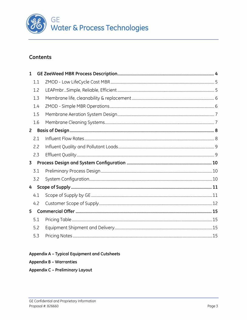
GE Confidential and Proprietary Information Proposal #: 826660 Page 3
Contents
1 GE ZeeWeed MBR Process Description ................................................................................... 4
1.1 ZMOD - Low LifeCycle Cost MBR ........................................................................................................... 5
1.2 LEAPmbr…Simple, Reliable, Efficient .................................................................................................... 5
1.3 Membrane life, cleanability & replacement ..................................................................................... 6
1.4 ZMOD - Simple MBR Operations ............................................................................................................ 6
1.5 Membrane Aeration System Design .................................................................................................... 7
1.6 Membrane Cleaning Systems ................................................................................................................. 7
2 Basis of Design ............................................................................................................................ 8
2.1 Influent Flow Rates ...................................................................................................................................... 8
2.2 Influent Quality and Pollutant Loads ................................................................................................... 9
2.3 Effluent Quality .............................................................................................................................................. 9
3 Process Design and System Configuration ......................................................................... 10
3.1 Preliminary Process Design ................................................................................................................... 10
3.2 System Configuration............................................................................................................................... 10
4 Scope of Supply ......................................................................................................................... 11
4.1 Scope of Supply by GE ............................................................................................................................. 11
4.2 Customer Scope of Supply ..................................................................................................................... 12
5 Commercial Offer ..................................................................................................................... 15
5.1 Pricing Table ................................................................................................................................................. 15
5.2 Equipment Shipment and Delivery ..................................................................................................... 15
5.3 Pricing Notes ................................................................................................................................................ 15
Appendix A – Typical Equipment and Cutsheets
Appendix B – Warranties
Appendix C – Preliminary Layout

GE Confidential and Proprietary Information Proposal #: 826660 Page 4
1 GE ZeeWeed MBR Process Description GE ZeeWeed Membrane The ZeeWeed membrane bioreactor (MBR) process is a GE technology that consists of a suspended growth biological reactor integrated with an ultrafiltration membrane system, using the ZeeWeed hollow fiber membrane. Essentially, the ultrafiltration system replaces the solids separation function of secondary clarifiers and sand filters in a conventional activated sludge system.
The ZeeWeed membrane has been designed for exceptional durability. This is achieved through a patented reinforced fiber backing to which the membrane with special chemical treatment is bonded. The reinforced fiber backing strengthens the membrane and protects it from breaking, without reducing its flux capacity.
ZeeWeed ultrafiltration membranes are immersed in an aeration tank, in direct contact with mixed liquor. Through the use of a permeate pump, a small suction is applied to a header connected to the membranes. The suction draws the treated water through the hollow fiber ultrafiltration membranes. Permeate is then directed to disinfection or discharge facilities. Intermittent airflow is introduced to the bottom of the membrane module, producing turbulence that scours the external surface of the hollow fibers. This scouring action transfers rejected solids away from the membrane surface.
ZeeWeed membrane bioreactor technology effectively overcomes the problems associated with poor settling of sludge in conventional activated sludge processes. ZeeWeed MBR
Constant flow/flux capacity is achieved by: Patented special chemical treatment for membrane surface Outside-in flow design keeps solids on the outside of the membrane Automated backpulse keeps solids away from the membrane pores Automated air scouring sweeps solids away from the membrane surface

GE Confidential and Proprietary Information Proposal #: 826660 Page 5
technology permits bioreactor operation with considerably higher mixed liquor solids concentrations than conventional activated sludge systems that are limited by sludge settling. The ZeeWeed MBR process is typically operated at a mixed liquor suspended solids (MLSS) concentration in the range of 8,000 to 10,000 mg/L. Elevated biomass concentrations allow for highly effective removal of both soluble and particulate biodegradable material in the waste stream. The ZeeWeed MBR process combines the unit operations of aeration, secondary clarification and filtration into a single process, producing a high quality effluent, simplifying operation and greatly reducing space requirements.
1.1 ZMOD - Low LifeCycle Cost MBR At the heart of ZMOD are the two most important parameters in a Low Lifecycle Cost MBR which are efficiency in MBR design & operation and the best chance of long membrane life in operation.
1.2 LEAPmbr…Simple, Reliable, Efficient ZMOD is designed to incorporate the latest innovations of LEAPmbr technology making ZMOD the most energy efficient and productive MBR that GE Water is able to provide to owners.
LEAPmbr’s combined initiatives will directly impact your plant design by:
Improving your Productivity by 15%,
Decreasing your membrane system footprint by 20%,
Removing equipment needed to provide aeration to your membranes by 50%,
Saving you over 30% in MBR power costs

GE Confidential and Proprietary Information Proposal #: 826660 Page 6
Figure 1: Example LEAP System - (Z-MOD-L)
1.3 Membrane life, cleanability & replacement ZMOD incorporates GE Water’s ZW500 membrane technology with the following key benefits to ensure an owner’s peace of mind for the life of their MBR facility:
ZeeWeed MBR membrane with a proven membrane life and high resistance to upset conditions
System designed with multiple cleaning options to ensure the highest chance of achieving maximum membrane life
GE Water as a single point of responsibility provides an integrated supply chain between the system & membrane warranty provider and the membrane manufacturer
A straight forward membrane warranty with clear performance triggers
1.4 ZMOD - Simple MBR Operations ZMOD is designed to ensure the MBR system is simple to operate without compromising any operational robustness.
The operators have a range of flexible options to ensure the MBR system is able to meet varying operating conditions should they arise.

GE Confidential and Proprietary Information Proposal #: 826660 Page 7
1.5 Membrane Aeration System Design Aeration is one of the most important operations for successful long term MBR operation and is a significant proponent of operating cost.
ZMOD utilizes a very simple aeration strategy which minimizes the amount of instrumentation and controls required to achieve a energy efficient method for membrane aeration.
No complex control loops or complicated airflow measurement devices are required for LEAP MBR Aeration Technology to achieve energy efficiency.
1.6 Membrane Cleaning Systems GE has developed MBR design principles based on best engineering practices that ensure the permeability of the membrane is maintained over the life of the membranes.
A fully automated suite of membrane maintenance procedures will ensure long-term, ation, including:
In situ chemical membrane cleaning performed directly in the membrane process tanks so your operators don’t waste time moving cassettes,
The ability to increase or decrease the frequency of maintenance cleans to fit the operating conditions.
The ability to backpulse when needed to greatly improve your operator’s ability to recover from non-design conditions.
The above cleaning systems are automated resulting in operators having available a full suite of comprehensive cleaning systems which are simple to use and initiate.

GE Confidential and Proprietary Information Proposal #: 826660 Page 8
2 Basis of Design 2.1 Influent Flow Rates After reviewing the plant information provided, GE understands that the following tank volumes are available:
Tank Name Number of Tanks Total Available Usable Tank Volume (Gallon) Reference
Pure Oxygen Tank 2 1,050,000
- Will still be used in the MBR system
- Oxygenation capacity is 20,000 lb O2/day at MLSS = 4.5 – 5 g/L
Secondary Flocculation Tank 4 180,000 Will be retrofit to biological
tanks
Final Settling Tank 6 1,250,000
One part of each final settling tank will be retrofit to membrane tank and the remainder will be changed to biological tank
Based on the available tank volumes, the resultant influent design flow rates can be increased as described in the table below:
Parameter Quantity Unit Average Day Flow 14.0 mgd Maximum Month Flow 16.8 mgd Maximum Day Flow 21.0 mgd Peak Hour Flow 28.0 mgd Maximum Flow with one train offline for maintenance or cleaning (less than 24 hrs) 18.2 mgd
Note: Any flow conditions that exceed the above-noted flow limits must be equalized prior to treatment in the membrane bioreactor unit.
Average Day Flow (ADF) – The average flow rate occurring over a 24-hour period based on annual flow rate data.
Maximum Month Flow (MMF) – The average flow rate occurring over a 24-hour period during the 30-day period with the highest flow based on annual flow rate data.
Maximum Day Flow (MDF) – The maximum flow rate averaged over a 24-hour period occurring within annual flow rate data.
Peak Hour Flow (PHF) – The maximum flow rate sustained over a 1-hour period based on annual flow rate data.

GE Confidential and Proprietary Information Proposal #: 826660 Page 9
2.2 Influent Quality and Pollutant Loads The design solution proposed is based on the wastewater characteristics detailed below.
Parameter Influent Characteristics
Current Pollutant Loads (lb/day)
Acceptable Maximum Influent Loads after Retrofit (lb/day)
Reference
Temperature 10 – 18 oC - -
BOD 199 mg/L 14,500 27,900 BOD, after Primary Clarifier 139 mg/L - - 30% removal in the
primary clarifier TSS 134 mg/L 9,840 18,787 TSS, after Primary Clarifier 67 mg/L - - 50% removal in the
primary clarifier TKN 25.2 mg/L 1,840 3,533 TKN, after Primary Clarifier 23.9 mg/L - - 5% removal in the
primary clarifier NH3-N 20.2 mg/L 1,480 2,832 TP 3.8 mg/L 275 533 Alkalinity n/a - -
2.3 Effluent Quality The following performance parameters are expected upon equipment start-up based on the data listed in Section 2.1 and 2.2 and the biological and membrane designs presented in Section 3.
Parameter Effluent Permit at 16.8 mgd (MMF)
Expected Effluent Quality Unit
BOD 14.9 (2,085 lb/day) 5 mg/L
TSS 17.8 (2,500 lb/day) 5 mg/L
NH3-N 2.8 (400 lb/day) 1 (1) mg/L
TP 1 1 mg/L
Settleable Solids 0.3 Not Detectable mg/L
Turbidity n/a 1 NTU
pH 6 - 9 6 - 9 SU Note: 1) Ammonia requirement is only for summer at a minimum temperature of 14°C.

GE Confidential and Proprietary Information Proposal #: 826660 Page 10
3 Process Design and System Configuration 3.1 Preliminary Process Design
Parameter Quantity Unit Reference
Aerobic 1: Pure oxygen tank volume 1,050,000 US gal
The MLSS concentration in the existing pure oxygen aeration system will be increased to around 8,000 mg/L. Other operating conditions will not change in the new MBR system.
Aerobic 2: Flocculation tank volume 180,000 US gal To be converted to aerobic tanks
Aerobic 3: Part of secondary clarifiers 766,700 US gal Retrofit of the existing final settling tanks.
Membrane Tank Volume 401,500 US gal Retrofit of the existing final settling tanks. Total MBR Volume 2,398,200 US gal Design HRT at MMF 3.43 Hour Design SRT at MMF 13.1 Day Design MLSS in aerobic tanks 8,000mg/L mg/L
3.2 System Configuration The following membrane design will be able to treat the flows presented in Section 2.1. Number of membrane trains in operation can be reduced as seasonal influent flow decreases.
Parameter Quantity/Description
Type of Membrane ZeeWeed® 500d Membrane Trains 6 Total Membrane Cassettes Installed Per Train 12 Total Membrane Cassette Space Per Train 14 Membrane Modules Installed Per Train 576 Membrane Cassettes Installed in the Plant 72 Membrane Modules Installed in the Plant 3,456

GE Confidential and Proprietary Information Proposal #: 826660 Page 11
4 Scope of Supply 4.1 Scope of Supply by GE
Quantity Description (1) ZeeWeed® Membranes 72 ZeeWeed® 500d membrane cassettes 3,456 ZeeWeed® 500d membrane modules 180 Membrane cassette support beams 72 sets Pins, hangers, hanger braces, and brackets for membrane cassette installation 72 sets Couplings, fasteners and gaskets 6 Permeate collection headers (316L SS) 6 Air distribution headers (304L SS) 72 Membrane cassette permeate isolation valves 72 Membrane cassette air isolation valves 6 Membrane tank level transmitters with isolation valves 12 Membrane tank level switches Permeate Pumping System 4 End-suction centrifugal pumps with associated isolation valves. 1 Temperature indicator 6 Pressure transmitters 6 Permeate magnetic flow meters 6 Air Extraction Systems 6 Permeate turbidity meters Backpulse Pumping System 1 + 1 End-suction centrifugal pumps with associated isolation valves. 1 Permeate magnetic flow meter 1 Permeate water main pressure indicator Membrane Air Scour System
3 Membrane air scour TURBO blowers, complete with required isolation valves, check valves.
6 Automatic butterfly valves for membrane aeration isolation Recirculation Pumps 6 Mixed Liquor Recirculation pumps with associated valves Biological Process Equipment 2 + 1 Process air TURBO blowers, complete with required isolation valves and check valves Lot Fine bubble diffusers 6 DO transmitter in the biological tanks 6 pH transmitter in the biological tanks 6 Level transmitter in the biological tanks Sludge Wasting 1 Wasted sludge magnetic flow meter

GE Confidential and Proprietary Information Proposal #: 826660 Page 12
Quantity Description (1) 1 Manual isolation valve 1 Automatic isolation valve Membrane Cleaning Systems
1 Wall-mounted sodium hypochlorite feed system - includes two (2) dosing pumps, and associated valves and piping
1 Wall-mounted citric acid feed system - includes two (2) dosing pumps, and associated valves and piping
Process Chemical Dosing Systems
1 Wall-mounted sodium hydroxide feed system - includes two (2) dosing pumps, and associated valves and piping
1 Wall-mounted ferric chloride feed system - includes two (2) dosing pumps, and associated valves and piping
Electrical Control 1 Master control panel with Allen Bradley PLC and HMI 6 Membrane train control I/O panels Miscellaneous 1 ZMOD-500D membrane cassette lifting module 1 + 1 Air compressors c/w associated refrigerated air driers, filter, pressure switch, and
valves General
Included Equipment general arrangement and layout drawings
Included Operating & maintenance manuals
Included Field service and start-up assistance (2) - 120 days support over 7 site visits from GE Water field-service personnel for equipment installation, commissioning, plant start-up and operator training
Included GE Insight Diagnostic and Monitor Service for the first year
Included 24/7 emergency phone support for the first year
Included Equipment mechanical warranty - 1 year or 18 months from shipment
Included Membrane warranty – 2 years membrane full replacement warranty Notes: 1) All GE supplied equipment is designed for installation in an unclassified area. 2) Additional field service hours will be billed separately from the proposed system capital cost at a rate plus
living and traveling expenses. Detailed GE Water service rates are available upon request.
4.2 Customer Scope of Supply All delivery or services not specified in the GE Scope of Supply are included in the Customer Scope of Supply. Supply by Installation Contractor or OTHERS includes but is not limited to:
Overall plant design
Review of Equipment Drawings and Specifications
Civil works, buildings, equipment foundation pads, etc. including but not limited to:

GE Confidential and Proprietary Information Proposal #: 826660 Page 13
Building for housing GE supplied equipment including permeate pumps, blowers, etc. Note: electrical equipment including the PLC may require air-conditioned rooms to prevent overheating of sensitive electronic equipment depending on local climatic conditions
Equipment access platforms, walkways, stairs, etc.
Pre-treatment 2 mm fine screens
Process and membrane tanks - retrofit of the existing secondary flocculation and final clarifier tanks
Chemical Storage day/bulk tanks
Lifting equipment for membrane cassettes service
Raw Sewage Influent facilities for collection and disposal of fine screenings
Raw materials and utilities during equipment start-up and operation
Laboratory Services after Performance Test
Operating and Maintenance Personnel during equipment Checkout, Start-Up and Operation
Receiving, unloading and safe storage of equipment at site until ready for installation
Storage of membrane cassettes on site if required and must meet GE’s requirements.
Equipment installation including but not limited to:
Installation of any other loose-shipped GE supplied equipment not listed specifically in the proposal
SCADA if required, and Integration of plant SCADA system, equipment and programming
MCCs, electrical switchgear, VFDs, panel boards, transformers and any other equipment necessary to provide power distribution and control for equipment included in the Membrane System Scope of Supply
Any disposal requirement for Glycerin purged from the membranes
Any disposal requirements for chemical cleaning waste
Process and utilities piping, pipe supports, hangers, valves etc. including but not limited to:
All interconnecting piping including pump and blower piping manifolds
Finished water storage, and pumping equipment
Installation materials for instrumentation and automatic pneumatic valves including but not limited to air/sample line tubing, fittings, isolating valves & mountings
Equipment anchor bolts, brackets, and fasteners for GE supplied equipment
Design for Seismic Zone and Wind load.

GE Confidential and Proprietary Information Proposal #: 826660 Page 14
Any on-site painting or touch-up painting of equipment supplied
Touch up primer and finish paint surfaces on equipment as required at the completion of the project
Installation materials for instrumentation and pneumatic automatic valves including but not limited to air, sample line tubing, fittings, isolating valves and mountings
Provision of temporary pre-commissioning screens prior to membrane tank, if required
Provision of any temporary piping, fittings and valving necessary for plant startup, as required.

GE Confidential and Proprietary Information Proposal #: 826660 Page 15
5 Commercial Offer 5.1 Pricing Table Pricing for the proposed equipment and services is summarized in the table below. All pricing is based on the operating conditions and influent analysis that are detailed in the Basis of Design in Section 2 of the proposal.
Item Price Unit
Budgetary MBR System Price per Scope of Supply of Section 4.1 $9,410,000 USD
The pricing herein is for budgetary purposes only and does not constitute an offer of sale. All orders are subject to review and acceptance by GE Water & Process Technologies.
5.2 Equipment Shipment and Delivery Equipment Shipment estimated at 32 to 41 weeks after order acceptance. The Buyer and Seller will arrange a kick off meeting after contract acceptance to develop firm shipment schedule.
Typical Drawing Submission and Equipment Shipment Schedule
10-14 weeks
2-3 weeks
20-24 weeks 2
weeks Acceptance of PO Submission of Drawings Drawings Approval Equipment Manufacturing Equipment Shipment Plant Operations Manuals
The delivery schedule is presented based on current workload backlogs and production capacity. If a formal purchase order is not approved within the period of validity of this proposal, the delivery schedule is subject to review and adjustment. The time indicated for approval submittals can be staged in order to provide design details in 3-4 weeks (P&IDs, Manufacturer’s cut sheet, Bill of Materials, etc.) with detailed fabrication drawings and electrical drawings being submitted at the end of the submission period.
5.3 Pricing Notes All prices quoted are in US dollars
All pricing is FCA Oakville, Canada.

GE Confidential and Proprietary Information Proposal #: 826660 Page 16
No taxes or duties are included in the above-noted pricing. All taxes and duties are for the account of the purchaser.
The equipment delivery date, start date, and date of commencement of operations are to be negotiated
Commercial Terms and Conditions shall be in accordance with GE’s Standard Terms and Conditions of Sale.
This proposal and the rates provided herein are subject to final site, environmental, and financial due diligence by GE Water & Process Technologies.
Seller’s price and delivery schedule are based on the assumption that Buyer will take delivery as and when foreseen by the schedule. Where this is not the case, the Parties must agree in advance an alternative place of delivery, failing which the Seller will be entitled to ship the equipment to storage.
Appendix A – Typical Equipment and Cutsheets
Appendix B – Warranties
Appendix C – Preliminary Layout

Appendix F – Full IFAS Conversion Vendor Information
GHD | Oak Orchard Wastewater Treatment Plant Capacity Expansion Evaluation, Onondaga County, NY 8615142.2

METEOR® SPECIFIC TECHNOLOGY
METEOR® IFAS/MBBR technology is based on proprietary polyethylene biofilm carriers, which, when added to a treatment basin, provide a large internal surface area for the growth of micro-organisms.
METEOR®
IFAS/MBBR Process
The Meteor® IFAS/MBBR technology offers flexible solutions to a multitude of biological process upgrade applications such as nitrogen removal, treatment capacity increase and wastewater reuse.
Carrier size, geometry and specific internal surface area are critical features. Our unique carriers have been designed with optimal performance in mind.
The upgrade to IFAS or MBBR often consists of simply adding carriers and screens to existing basins and can therefore be completed in a cost-effective and timely manner without major civil engineering requirements and no requirement for additional land. PLC based control system optimize IFAS/MBBR process performance by minimizing energy and chemical costs.
» The METEOR® process can be used for a wide range of biological treatment applications: • Increased Flow Capacity • BOD Removal Enhancement • Nitrification for Ammonia Removal • Total Nitrogen Removal • Total Nitrogen and Phosphorus
Removal
APPLICATIONS
INFILCO
» IFAS/MBBR systems were designed to optimize mass transfer, biomass density and contaminant removal rates through intensive research.
» The combination of large aperture area, high specific biomass and UV resistance makes Meteor® well suited for IFAS/MBBR applications.
» A 22mm diameter carrier offers the ability to utilize a larger screen mesh size, thereby minimizing headloss across the screen and the tendency to foul.
» Highly resilient process for flow and contaminant loading variations.
WASTEWATER
MAIN FEATURES

IFAS, the integrated fixed film activated sludge (Meteor®) process incorporates the positive traits of two fundamental biological treatment processes, namely fixed-film technology and suspended growth technology (conventional activated sludge), together into one hybrid system.
By combining high biomass quantities typical of IFAS fixed-film technologies with fluidization typical of a conventional activated sludge (CAS), the Meteor® technology achieves high removal rates in a small volume.
Conventional activated sludge bioreactors are generally retrofitted with the addition of IFAS carrier retaining screens and modifications to the aeration grid to accommodate the addition of IFAS biofilm carriers. The media facilitates the growth of attached biomass and due to its size, is fluidized throughout the bioreactor.
In MBBR systems all the biomass is supported on the biofilm carrier with no recycled activated sludge.
This attached growth significantly increases the microbial population within the tank, thereby increasing the SRT of the system without increasing the suspended growth population.
Such conditions are conducive to the proliferation of nitrifying autotrophic bacteria and can be designed to ensure that a sufficient population exists to maintain nitrification through cold water conditions when process kinetics slow down. The biofilm carriers can also be added to anoxic tanks to improve denitrification, if necessary.
These characteristics make Meteor® technology an attractive option for upgrading existing BOD removal facilities for nitrogen removal in response to new regulatory requirements without costly physical expansion. Since addition of biofilm carriers reduces/eliminates dependence on the suspended growth phase, this technology is also advantageous after secondary treatment where virtually no mixed liquor suspended solids (MLSS) are available.
HOW IT WORKS
» Easy installation» Nitrifi cation and denitrifi cation in cold water
conditions» Minimal plant downtime for process implemen-
tation» Non-invasive basin retrofi t» Adaptable to many basin geometries, process designs and confi gurations» Quick system start-up» Requires no additional land» Operating procedures are unchanged
PRODUCT HIGHLIGHTS
INFILCO METEOR®
METEOR® : An easy-to-implement and cost eff ective way to upgrade WWTPs
CARRIERS
SCREEN

» Increased capacity of activated sludge basins by 100% to 200% with an in-basin retrofi t
» Upgrade of existing BOD removal facilities to full nitrifi cation and total nitrogen removal in response to new regulatory requirements:- Ammonia removal to < 1 mg/L NH3-N- Nitrate removal to < 1 mg/L NO3-N- Total Nitrogen removal to < 3 mg/L TN
» Suspended solids with better settling characteristics than that from conventional activated sludge
» Reduced suspended growth MLSS after a retrofi t, resulting in reduced solids loading on the clarifi ers
» Increase in oxygen transfer effi ciency due to the presence of the media
TECHNICAL FEATURESBIOFILM CARRIER ADVANTAGESMultiple basin configurations are possible depending on existing installations and effluent objectives (i.e. roughing reactor before CAS for enhanced BOD removal, separate stage nitrification and/or denitrification following CAS, MLE process or 4-stage process for total nitrogen removal, or a 5-stage process for TN and TP removal).
• Unique biofilm carriers were developed specifically for IFAS®/MBBR operation with high MLSS values – other media were designed for operation with no return sludge. The geometry of the carrier prevents overgrowth and provides excellent mass transfer.
• The biofilm carriers have larger apertures (internal openings) to prevent and resist clogging tendencies. The large apertures are designed to allow high mass transfer rates to promote active treatment productivity.
• The biofilm carriers are significantly larger than other free-floating media types. The larger media size allows installation of screens that have much larger openings. This mitigates the impact of overall plant headloss that can be a problem for processes employing smaller media.
BIOFILM CARRIER OPTIONS• Surface area - 450 m2/m3 • Surface area - 515 m2/m3
MECHANICAL ADVANTAGES• The biofilm carriers are made from high quality High Density
Polyethylene (HDPE), and unlike other media, are formulated with UV inhibitors for a long service life (twenty years or more) even in open basins exposed to constant sunlight.
• Meteor® process is compatible with both coarse and fine bubble aeration. Some competing media are not compatible with fine bubble due to reduced scour of small apertures in the media.
TECHNICAL ADVANTAGES
WASTEWATER
RAW WASTEWATER SCREEN / GRIT METEOR®-C PRIMARYCLARIFICATION
METEOR®-C-N-DN
METEOR®-N-DNSECONDARYCLARIFICATION
TERTIARYFILTRATION
UV, OZONE, or CI
2 DISINFECTION
METEOR® IN THE TREATMENT LINE

COMPLETE TREATMENT SOLUTIONSInfilco Degremont offers an array of water, wastewater and industrial treatment solutions for any size client. Headworks, clarification, filtration, biological and disinfection systems are several of the product disciplines in our portfolio. With a
variety of product disciplines in our BIOLOGICAL department, our engineers carefully evaluate each application to provide the most cost-effective and efficient treatment solution.
• Biofor®
• Ferazur®/Mangazur®
• METEOR®
• Climber Screen®
• Helico®
• Vortex
• ABW®
• Cannon Mixer®
• 2PAD • Thermylis • DensaDeg®
• AquaDAF®
If interested in this product, check out some of the complementary products:
SERVICES - INFILCARE™
PILOTING SERVICESInfilco Degremont offers pilot systems and services for this and many other of our product offerings. Pilot studies are a practical means of optimizing physical-chemical and biological process designs and offer the client several benefits, such as:
• Proof of system reliability• Optimal design conditions for the full-scale system• Free raw water lab analysis• Regulatory approval
If interested in a pilot study for this system, please contact us for a proposal and more information.
PART SALES
Infilco Degremont sells parts and components for most INFILCO brand equipment as well as parts for demineralizers, thickeners, nozzles, pressure filters, and valves. We offer reliable spare parts at competitive prices. We maintain records of previous installations to quickly identify your requirements. Many items are shipped directly from stock for quick delivery.
REBUILDS, RETROFITS AND UPGRADES
Infilco Degremont offers cost-effective rebuilds and upgrades for INFILCO provided systems, no matter what year they were built. If you are interested in an economical alternative to installing a whole new system, contact us for a proposal.
INFILCO DEGREMONT INC.8007 Discovery DriveRichmond, VA 23229-8605, USATel: +1 804 756 7600Fax: +1 804 756 7643info-infi [email protected]
DEGRÉMONT LIMITÉE1375, route Transcanadienne, Bureau 400Dorval (Qc) H9P 2W8, CanadaTel: +1 514 683 1200Fax: +1 514 683 [email protected]
CONTACTS WWW.DEGREMONT-TECHNOLOGIES.COM
Copyright © 2010 Infilco Degremont Inc., Degremont Technologies - BOS03202EN-V3-08/2010 - Subject to change without prior notice, contact Degremont Technologies for more information.
INFILCO METEOR®WASTEWATER

METEOR® IFAS System
Design Proposal
Project: Oak Orchard WWTP, NY
Engineer: GHD Proposal No. 50136944.01
Date: June 10, 2013

INFILCO DEGREMONT INC.
8007 DISCOVERY DRIVE, RICHMOND, VA 23229 USA P.O. BOX 71390, RICHMOND, VA 23255-1390 USA TEL 804 756-7600 | FAX 804 756-7643
WWW.DEGREMONT-TECHNOLOGIES.COM HEADWORKS | BIOLOGICAL | SEPARATIONS | MEMBRANES | OXIDATION-DISINFECTION | BIOSOLIDS | INDUSTRIAL SYSTEMS
June 10, 2013
Jason Greene GHD Re: Oak Orchard WWTP, NY
METEOR IFAS System Inquiry No. 50136944.01 Dear Mr. Greene: With regard to your recent request for a proposal for the Oak Orchard WWTP, NY, Infilco Degremont, Inc. (IDI) is pleased to submit a preliminary proposal for a METEOR® system for your review. The process has been designed for treating the primary effluent with a design flow of 10 MGD (assumed peak flow 20 MGD) by implementing a METEOR® system in the BOD Removal/Nitrification IFAS configuration by utilizing the entire volume of the two (2) existing HPOAS tanks to bring effluent BOD to < 25 mg/l year round and seasonally (summer) Ammonia-N to < 4.8 mg/l. The maximum system capacity was also modeled and it was seen that a design flow of up to 12.5 MGD can be treated to the above limits. The system is currently limited hydraulically, as in the absence of HRT constraints and with the addition of more media, an even higher flow could be potentially treated. If the secondary flocculation tank volume can also be included with the HPOAS volume then the combined tankage modified with an IFAS can treat flows up to 14.75 MGD to the effluent limits mentioned above. It may be noted that in case of the HPOAS IFAS retrofit, the existing HPOAS pure oxygen generation aeration system would be replaced by a standard fine diffused air aeration system (latter included as part of scope of supply for IFAS system). We have endeavored to provide complete information in this proposal. However, if you have any questions or need additional information, please feel free to contact Randy, our regional sales representative, or me directly. Sincerely,
Mudit Gangal Senior Application Engineer - Biological Systems Group

INFILCO DEGREMONT INC.
8007 DISCOVERY DRIVE, RICHMOND, VA 23229 USA P.O. BOX 71390, RICHMOND, VA 23255-1390 USA TEL 804 756-7600 | FAX 804 756-7643
WWW.DEGREMONT-TECHNOLOGIES.COM HEADWORKS | BIOLOGICAL | SEPARATIONS | MEMBRANES | OXIDATION-DISINFECTION | BIOSOLIDS | INDUSTRIAL SYSTEMS
Regional Business Manager Mervyn Bowen Degremont Technologies - Infilco P. O. Box 71390 Richmond, VA 23255-1390 Tel: 804/756-7786 Fax: 804/756-7643 Email: [email protected]
Sales Representative Randy Ott GP Jager & Associates, Inc.
7505 Moccasin Path Liverpool, NY 13090 Tel: 315/652-5627 Fax: 315/944-3199 Email: [email protected]

IDI METEOR® SYSTEM
WWW.DEGREMONT-TECHNOLOGIES.COM HEADWORKS | BIOLOGICAL | SEPARATIONS | MEMBRANES | OXIDATION-DISINFECTION | BIOSOLIDS | INDUSTRIAL SYSTEMS
TABLE OF CONTENTS
1. APPLICATION .................................................................................................... 4
1.1 Project Background .......................................................................................... 4
1.2 Process Design Basis ........................................................................................ 4
2. TREATMENT APPROACH ................................................................................... 5
2.1 METEOR® DESIGN ............................................................................................. 6
2.2 Design Analysis ................................................................................................. 7
2.3 Aeration System ................................................................................................ 8
2.4 NutriCell™ 450 Biofilm Carriers ....................................................................... 8
2.5 Carrier Retaining Screens ................................................................................. 9
3. SCOPE ............................................................................................................... 10
3.1 Scope of Supply................................................................................................ 10
4. BUDGET PRICE ................................................................................................. 14

IDI METEOR®
SYSTEM
Oak Orchard WWTP, NY 4 Proposal No. 50136944.01
1. APPLICATION
1.1 Project Background
The Oak Orchard WWTP, NY is looking at upgrading its facilities to increase treatment capacity and meet strict effluent limits. An Integrated Fixed Film Activated Sludge (IFAS) process is attractive to the client as it allows removal of pollutants in a compact footprint without the need to build additional tanks. The system has been designed for a flow of 10 MGD. The objective of the proposed design is to treat the primary effluent flows with design conditions listed in Table 1 and achieve year round effluent BOD < 25 mg/ and seasonal (summer) effluent Ammonia-N less than 4.8 mg/l.
1.2 Process Design Basis
The METEOR® system design and performance is based on the design information provided by GHD. Table 1 summarizes the flows and water quality parameters used for the proposed design.
Table 1. Design Parameters for Oak Orchard WWTP, NY
Treatment Parameter Influent Treated Effluent
Design Flow, MGD 10
Peak Flow, MGD 20 (assumed)
Design Temperature, oC 141
MLSS, mg/l 4,500
BOD5, mg/l 149
< 25
TSS, mg/l 72
TKN, mg/l 24.71
NH3-N, mg/l 19.75
< 4.82
1 For seasonal Nitrification which is the governing design condition. For BOD Removal a design temperature of 10 °C has been used
2 From June 16 to October 31
Note: The IFAS system is not designed for Phosphorus Removal and any reduction in the same is incidental

IDI METEOR®
SYSTEM
Oak Orchard WWTP, NY 5 Proposal No. 50136944.01
2. TREATMENT APPROACH
The biological process proposed is the METEOR® system, which is an Integrated Fixed Film Activated Sludge (IFAS) biofilm carrier process. The concept consists of
addition of NUTRICELL™450 biofilm carriers, carrier retaining screens and aeration system to the METEOR® system basin. This process employs proprietary mobile
biomass carriers (NUTRICELL™450) to support a very high concentration of
attached biomass. The neutrally buoyant HDPE NUTRICELL™450 biofilm carriers within each bioreactor tank provide a stable base for the growth of a diverse community of micro-organisms.
The attached growth biofilm carriers have a very high surface-to-volume ratio, allowing for a high concentration of biological growth to thrive within the internally protected areas. The detached biomass from the attached growth biofilm carriers will remain suspended within the Fluidized Fixed Film reactor, and is continuously removed from the process by the existing flow stream, resulting in an operator free biological system.
METEOR® Process Advantages:
� Increased Nitrification - via biofilm retention in basin. Nitrifiers on the biofilm carriers have extended retention time and proliferate resulting in consistently low effluent Ammonia-N
� Improved Process Stability - during peak flow conditions resulting from retention of biomass in treatment basin
� NUTRICELL™450 - biofilm carriers were specifically designed for hybrid applications allowing large screen openings and biofilm carrier apertures. Local production in the US minimizes shipping, duties and installation time.
� Field Proven at Full Scale - Has recently been selected for similar plants such as Moorhead, MN, the Region of Peel (Canada), City of Raisio (Finland), Groton, CT, Falling Creek, VA and Proctor’s Creek, VA, East Providence WWTP, RI and has been evaluated using full-scale testing at the Waterdown WWTP.
� Upgrade Within Existing Basin - Enables the upgrade of conventional activated sludge plants without additional real estate.
Conventional activated sludge processes may experience inconsistent Nitrification at low Solids Retention Times (SRT) due to fluctuations in flow and operation. The biomass retention offered by biofilm carriers maintains a stable population of heterotrophic bacteria, despite flow variation that would otherwise cause washout.
The fixed film nature of NUTRICELL™450 prevents washout, and provides a larger biomass population, resulting in a consistent effluent at lower suspended solids SRTs.

IDI METEOR®
SYSTEM
Oak Orchard WWTP, NY 6 Proposal No. 50136944.01
Biomass retention on the carriers enables a much lower solids load to pass through the downstream units, for the biofilm is retained in the aeration basin. The biofilm thickness and mass is self-regulating, responding to both high and low mass loadings.
2.1 METEOR® DESIGN
The system for the Oak Orchard WWTP, NY has been designed using proprietary models to perform process selection and to determine the optimal biofilm carrier fill fractions and other operating parameters. An extensive analysis of design alternatives revealed that a BOD Removal/Nitrification METEOR® (IFAS Biofilm Carrier process) would be suitable for the application as it is capable of achieving the desired effluent BOD/Ammonia-N values.
The processes proposed comprise the following stages of treatment:
1. Preliminary treatment will consist of influent screening (6 – 9 mm) and primary clarification.
2. The METEOR® process will be implemented in the two existing HPOAS tanks by the addition of biofilm carriers and installation of screens and an aeration system. System setup is based on the increased ability of the modified system to bring about BOD and Ammonia-N reduction due to the addition of biofilm carriers. This process is ideal for achieving low effluent BOD and Ammonia-N levels.
3. NUTRICELL™450 biofilm carriers will be added to the tanks, resulting in increased biomass concentrations due to the active biomass growth on the biofilm carriers. The attached biomass on the biofilm carriers will enhance the BOD removal/Nitrification function without increasing basin MLSS, thereby optimizing the use of the secondary clarifiers. Air will be supplied to the aeration tank by means of existing blowers and if necessary, by new blowers.
4. Our proposal includes the cost of providing a complete new fine bubble diffused aeration system.

IDI METEOR®
SYSTEM
Oak Orchard WWTP, NY 7 Proposal No. 50136944.01
Figure 1. Process Schematic of the METEOR® process
2.2 Design Analysis
A summary of the METEOR® IFAS design is provided in Table 2.
The design has the following main features:
• Sixty one percent (61%) fill fraction of biofilm carriers is recommended in the IFAS tanks for a design flow of 12.5 MGD (max capacity). A lower fill fraction would be needed to treat the current design flow of 10 MGD.
Table 2. Design Summary for Oak Orchard WWTP Project
Parameter Design 1
Flow MGD 12.5
NH3-N mg/l < 4.81
BOD mg/l < 25
Aerobic Zone (R2) Volume gal 1,046,920
Biofilm carrier fill in R2 % 61
Biofilm carrier Type NUTRICELL™450
Biofilm carrier Surface Area m2/m3 450
Biofilm carrier Volume m3 2,417
Carrier Retaining Screens # 10
Process Air Flow Required scfm 13,525
1 Seasonal (Summer) limit

IDI METEOR®
SYSTEM
Oak Orchard WWTP, NY 8 Proposal No. 50136944.01
2.3 Aeration System
Air requirement is based on the estimated amount of oxygen required and the amount of air needed to thoroughly mix the bioreactor. The total air requirement for the proposed designs is indicated in Table 2. Note that this air requirement is based on a fine bubble air diffusion system at 18 oC.
The aeration system will consist of 304L stainless and PVC vertical dropleg including elbow and vertical flange for connection to the air main at the top of the tank and bottom connection to the air manifold. Piping upstream of flanged elbow will be provided by others. The dropleg will be connected to Schedule 40 PVC manifold which will have further connections to each air distributor header. The manifold pipes will be provided with stainless steel supports and hold down strap, cradle and adjusting and locking mechanism. The PVC distribution headers will consist of factory installed diffuser holders, positive locking fixed anti-rotational joint connections, support stands with hold down clamp, locating plate and anchor bolts. The aeration system for each grid will be complete with a purge system with eductor piping and isolation valve.
The fine bubble aeration system is provided due to its primary advantage of higher oxygen transfer efficiency and consequent lower air requirements and energy costs as compared to coarse air bubble aeration system.
2.4 NutriCell™ 450 Biofilm Carriers
The fluidized fixed film reactor utilizes NUTRICELLTM450 biofilm carriers.
NUTRICELLTM450 has the following advantages for this application:
� Automatically Responds to Load Fluctuations - As the contaminant load
increases, the microbial population in the biofilm increases, enabling additional treatment capacity. Likewise, during low loading conditions, the population self adjusts and decreases through aggressive sloughing action.
� Resilient to Toxic Shocking – in a toxic situation, the outer layer of dead bacteria is removed by normal detachment mechanisms present in the bioreactor while the inner layer provides a seed for microbial growth and enables the system to continue treatment of the contaminant load
� High Surface Area Fixed Film Biomedia - Suspended carrier elements designed for high rate fixed-film biological digestion within a small footprint.
� Biomass Retention – Nitrifiers are protected from washout by retention in the basin on the biomass carrier. Recovery period following suspended biomass washout is significantly reduced due to the retention of fixed film biomass in the system and constant re-seeding of the basin with nitrifiers.

IDI METEOR®
SYSTEM
Oak Orchard WWTP, NY 9 Proposal No. 50136944.01
Figure 1. NUTRICELLTM450 Biomass carrier with biofilm growth, as an example
2.5 Carrier Retaining Screens
The biofilm carriers retaining screens are horizontal in orientation (Figure 2) that can be flange or slide-in mounted. The screens are manufactured from 304L stainless steel wedge wire. Each screen has abundant open area, with slot widths of 3/8” (10 mm) to provide excellent flow capacity. The biomass carriers constantly scour the screen surface and keep it free from debris. The large size of biomass carriers enables large screen openings, resulting in significantly reduced headloss across the screens, and less of a tendency to foul. The headloss through the screens is expected to be less than 0.5 inch. The total number of screens is based on hydraulically handling the assumed peak flow of 20 MGD plus RAS flow of 6.25 MGD (Total = 26.25 MGD). Each screen is designed for a flow of 40 gpm/ft2. Therefore, each 36-inch diameter and 60-inch long cylindrical screen is designed for a flow 1,885 gpm.
Figure 2. Typical cylindrical flange mounted screen (assembly)

IDI METEOR®
SYSTEM
Oak Orchard WWTP, NY 10 Proposal No. 50136944.01
3. SCOPE
3.1 Scope of Supply
The following table outlines Degremont’s METEOR® system scope of supply.
Item Qty. Description
1 2,419 m3
NUTRICELL™450 Biofilm carriers delivered in super sacks
2
10 2 4
304 L SS Biofilm Carriers Retaining Screens; 36” dia x 60” long Horizontal Cylindrical Screen Assemblies including
• Mounting hardware
• Overflow Screens
• Drain screens
3 1 Fine Bubble aeration system with diffusers, basin piping for c/w drop legs, flanged diffuser pipes, mounting brackets and connection fasteners. Capacity: 13,525 SCFM
4 2 Sets of O&M Manuals
5 2 Sets of Detailed Shop Drawings
6 20 Service Days, to inspect equipment installation, test all supplied components, assist in start-up and train plant personnel.

IDI METEOR®
SYSTEM
Oak Orchard WWTP, NY 11 Proposal No. 50136944.01
3.2 Items by Others
The following items are specifically not by Infilco Degremont. They may or may not be required.
General
• Air Main Piping and all accessories including valves, bolts gaskets and connectors for attaching to drop pipes
• Non-potable water supply
• Chemical Feed Systems for alkalinity correction, methanol and defoamer
• Overflow structures including baffles and weir plates
• Chemicals for operation: Including methanol, alkaline solution, defoamer
• Online instrumentation such as pH, DO, Temperature, etc.
• Cleanouts • Power
• Concrete • Process air blowers
• Control Panel • Recirculation Piping and Supports
• Drains • Sludge handling and disposal
• Engines/Generators • Support Platforms
• Foam control • Transformers
• Hoses /Bibs • Variable Frequency Drives
• Laboratory • Ventilation
• Ladders • Walkways/Roofing/Stairs/Gratings/Handrails
• Lighting • Wireways/Wiring
• Liquid sampling and analytical work • Yard Hydrants
• Motor Control Center (MCC) • Yard Piping

IDI METEOR®
SYSTEM
Oak Orchard WWTP, NY 12 Proposal No. 50136944.01
3.3 Additional Items by Installing Contractor
1. Obtain necessary construction permits and licenses, construction drawings
(including interconnecting piping drawings) field office space, telephone service, and temporary electrical service.
2. All site preparation, grading, locating foundation placement, excavation for foundation, underground piping, conduits and drains.
3. Demolition and/or removal of any existing structures, equipment or facilities required for construction and installation of the METEOR® system.
4. Installation of all foundation - supply and installation of all embedded or underground piping, conduits and drains.
5. All backfill, compaction, finish grading, earthwork and final paving.
6. Receiving (preparation of receiving reports), unloading, storage, maintenance preservation and protection of all equipment and materials supplied by Infilco.
7. Installation of all equipment and materials supplied by Infilco.
8. Supply, fabrication, installation, cleaning, pickling and/or passivation of all interconnecting steel piping components.
9. Provide and install all embedded pipe sections and valves for tank drains and reactor inlets and elbows.
10. All cutting, welding, fitting and finishing for all field fabricated piping.
11. Supply and installation of all flange gaskets and bolts for all piping components.
12. Supply and installation of all pipe supports and wall penetrations.
13. Install and provide all motor control centers, motor starters, panels, field wiring, wireways, supports and transformers.
14. Install all control panels and instrumentation as supplied by Infilco, as applicable.
15. Supply and install all electrical power and control wiring and conduit to the equipment served plus interconnection between the Infilco equipment as required, including wire, cable, junction boxes, fittings, conduit, cable trays, safety disconnect switches, circuit breakers, etc.
16. Supply and install all insulation, supports, drains, gauges, hold down clamps, condensate drain systems, flanges, flex pipe joints, expansion joints, boots, gaskets, adhesives, fasteners, safety signs, and any specialty items such as traps.
17. All labor, materials, supplies and utilities as required for start-up including laboratory facilities and analytical work.
18. Provide all chemicals required for plant operation and all chemicals, lubricants, glycol, oils or grease and other supplies thereafter.

IDI METEOR®
SYSTEM
Oak Orchard WWTP, NY 13 Proposal No. 50136944.01
19. Install all anchor bolts and mounting hardware supplied by Infilco; and supply and install all anchor bolts and mounting hardware not specifically supplied by Infilco.
20. Provide all nameplates, safety signs and labels.
21. Provide all additional support beams and/or slabs.
22. Provide and install all manual valves.
23. Provide and install all piping required to interconnect to the Infilco’s equipment.
24. The Contractor shall coordinate the installation and timing of interface points such as piping and electrical with the Infilco Supplier.
All other necessary equipment and services not otherwise listed as specifically supplied by Infilco.
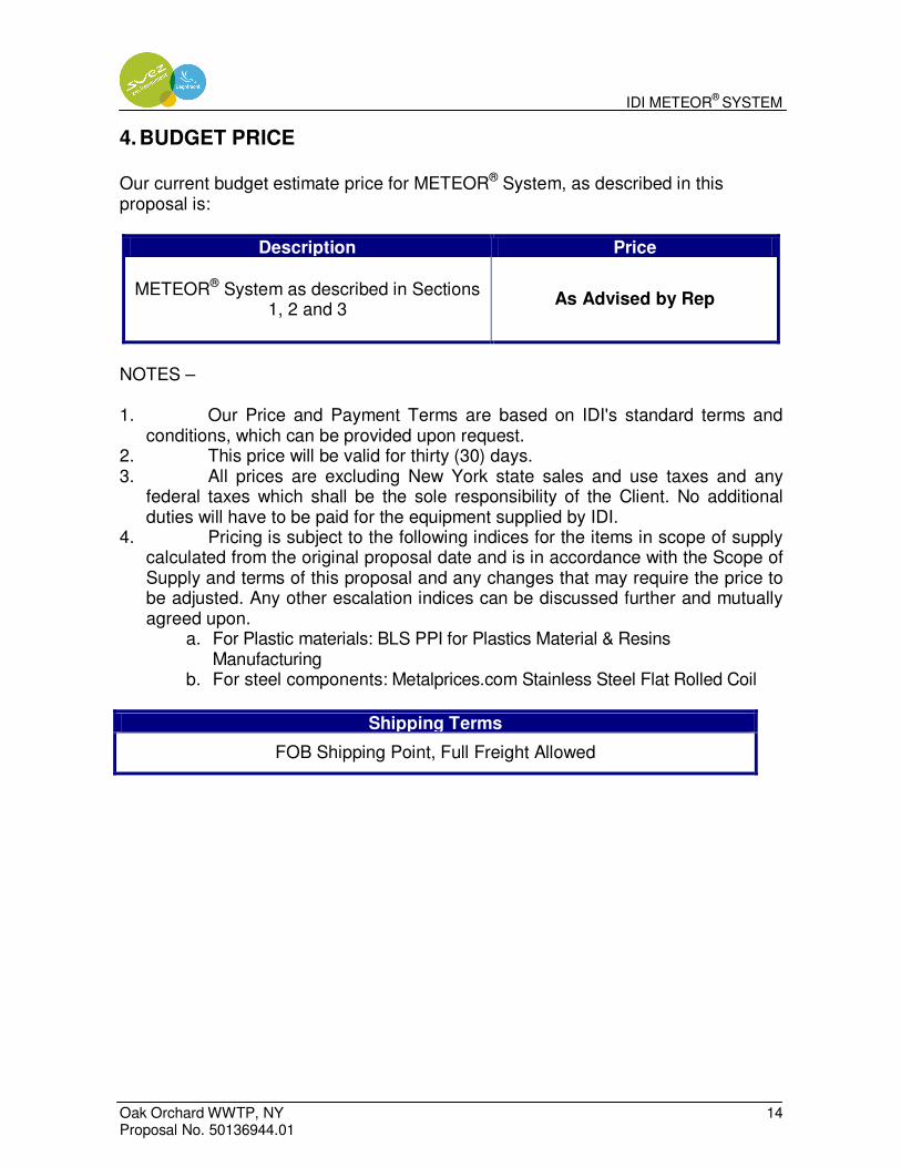
IDI METEOR®
SYSTEM
Oak Orchard WWTP, NY 14 Proposal No. 50136944.01
4. BUDGET PRICE
Our current budget estimate price for METEOR® System, as described in this proposal is:
Description Price
METEOR® System as described in Sections 1, 2 and 3
As Advised by Rep
NOTES – 1. Our Price and Payment Terms are based on IDI's standard terms and
conditions, which can be provided upon request. 2. This price will be valid for thirty (30) days. 3. All prices are excluding New York state sales and use taxes and any
federal taxes which shall be the sole responsibility of the Client. No additional duties will have to be paid for the equipment supplied by IDI.
4. Pricing is subject to the following indices for the items in scope of supply calculated from the original proposal date and is in accordance with the Scope of Supply and terms of this proposal and any changes that may require the price to be adjusted. Any other escalation indices can be discussed further and mutually agreed upon.
a. For Plastic materials: BLS PPI for Plastics Material & Resins Manufacturing
b. For steel components: Metalprices.com Stainless Steel Flat Rolled Coil
Shipping Terms
FOB Shipping Point, Full Freight Allowed

Appendix G – Webitat Media in Effluent Lagoons Vendor Information
GHD | Oak Orchard Wastewater Treatment Plant Capacity Expansion Evaluation, Onondaga County, NY 8615142.2

400 Silver Cedar Court, Suite 200, Chapel Hill, NC 27514 919.933.2770 phone 919.287.2258 fax www.ENTEXinc.com
June 18, 2013 To: Jason Greene, Project Engineer GHD, Inc. 1 Remington Park Drive
Cazenovia NY 13035 Sub: Oak Orchard NY WWTP: ENTEX WebitatTM for Lagoons Dear Jason, Thank you for the opportunity to present a conceptual design for the Oak Orchard WWTP. We understand the near-term objective includes increasing the existing treatment capacity without constructing new tankage. Based on the information provided, ENTEX proposes incorporating a Webitat fixed-film process into the existing lagoon system. The proposed Webitat system will allow the lagoon process to treat an additional 209 ppd of NH3 (equivalent 1 MGD at 25 ppm influent NH3). The Webitat process will create a series of self-sustained, high rate biological reactors. Additionally, the Webitat system is capable of providing several key process benefits:
1. Increased stabilized biomass and process stability 2. Aeration cycling for energy optimization and denitrification 3. No baffles, covers or earthwork required for Webitat IO&M 4. Minimized solids inventory management compared to other processes
ENTEX’s scope of supply includes a total of Thirty (30) Webitat modules. Each Webitat unit will be equipped with an integral aeration grid for scour and oxygen transfer. A blower will be dedicated to the Webitat processes. Aeration valving and an ENTEX Control system will be included to automate Webitat sequences. ENTEX’s budgetary quotation for this scope of supply is $1,820,550.00. Should you have any questions regarding the information found in this proposal, do not hesitate to contact ENTEX. Sincerely,
Jason Bowman Regional Manager

ENTEX Technologies Inc. Page 2
Basis of Design ENTEX’s design assessment has been based on the conditions shown below. It is assumed that sufficient screening is in place to minimize debris, inerts and solids (screening by others). The Webitat Lagoon process has been modeled in the absence of a Return Activated Sludge to minimize solids inventory management. The Webitat system has been conservatively modeled by assuming prior treatment processes have no impact on ammonia. Therefore, all nitrification is assumed to occur in the Webitat lagoon processes. Should, for example, the assumption be modified to treat 50% of the ammonia, the number of Webitat units required will decrease proportionally.
Parameter Influent
Flow, mgd 1.0
BOD, mg/L 240
TSS, mg/L 160
Ammonia, mg/L 25
pH 7-8
Temp, °C 7 (min)
Alkalinity, mg/l CaCO3 200 Design Concept ENTEX’s Webitat system is engineered to actively manage the attached biomass environment to optimize kinetic rates. These high rate reactors enhance mixing and substrate transfer, while adding aeration and fixed biomass to an otherwise limited treatment environment. ENTEX has determined that a total of Thirty (30) Webitat modules will be required to provide surface area for added nitrification capacity. A total of ~220,000 square feet of BioWeb media will be used. The Webitat modules should be divided equally among the lagoons. ENTEX recommends continuous operation of the Webitat aeration to create a series of complete mixed reactors. This will minimize bypass and further increase substrate contact time. Note: Depending upon the plants seasonal treatment objectives and energy considerations, each Webitat system has the ability to run in either full aerobic mode or alternating aerobic-anoxic mode. In this manner, Webitat can enhance denitrification to recover alkalinity and oxygen, as well as decrease operational costs by minimizing blower draw. ENTEX recommends establishing nitrification prior to cycling Webitat units.

ENTEX Technologies Inc. Page 3
Operation ENTEX’s Webitat process utilizes a high rate air scour through an enclosed fixed-film module to create a large air lift pump mechanism. This arrangement ensures a high shear of the attached growth biomass and further increases kinetic performance by continually circulating substrate. In this manner, the substrate-biological contact time is increased. Additionally, the shearing action helps to seed the rest of the lagoon. The Webitat modules arrive completely assembled. Each module weighs ~2,000 lbs and can be lowered into the lagoon with a crane. The only connections necessary are to connect a 3-inch airline to the top of each Webitat module to main process aeration header located on the lagoon bank. Each module will have a dedicated 3-inch drop pipe with a male NPT connection (bolts, hose, fittings, and or additional piping outside of the Webitat modules are not included within this proposal). Each Webitat module will operate at a minimum 30-35 scfm and will have a dedicated motor actuated 3-inch valve for flow adjustment/isolation. Each valve will be located along the lagoon bank for easy access. A dedicated Webitat blower will provide aeration to the Webitat units. A dedicated Webitat PLC will be incorporated to automate Webitat process and provide operational flexibility. The existing surface aerators will remain unaffected.
Figure #1. Webitat modules with integral aeration.
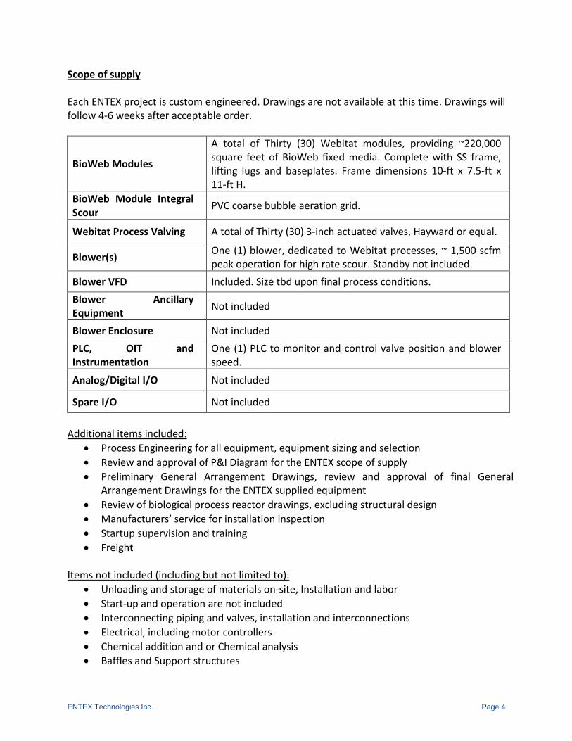
ENTEX Technologies Inc. Page 4
Scope of supply Each ENTEX project is custom engineered. Drawings are not available at this time. Drawings will follow 4-6 weeks after acceptable order.
BioWeb Modules
A total of Thirty (30) Webitat modules, providing ~220,000 square feet of BioWeb fixed media. Complete with SS frame, lifting lugs and baseplates. Frame dimensions 10-ft x 7.5-ft x 11-ft H.
BioWeb Module Integral Scour PVC coarse bubble aeration grid.
Webitat Process Valving A total of Thirty (30) 3-inch actuated valves, Hayward or equal.
Blower(s) One (1) blower, dedicated to Webitat processes, ~ 1,500 scfm peak operation for high rate scour. Standby not included.
Blower VFD Included. Size tbd upon final process conditions. Blower Ancillary Equipment Not included
Blower Enclosure Not included PLC, OIT and Instrumentation
One (1) PLC to monitor and control valve position and blower speed.
Analog/Digital I/O Not included
Spare I/O Not included
Additional items included:
• Process Engineering for all equipment, equipment sizing and selection • Review and approval of P&I Diagram for the ENTEX scope of supply • Preliminary General Arrangement Drawings, review and approval of final General
Arrangement Drawings for the ENTEX supplied equipment • Review of biological process reactor drawings, excluding structural design • Manufacturers’ service for installation inspection • Startup supervision and training • Freight
Items not included (including but not limited to): • Unloading and storage of materials on-site, Installation and labor • Start-up and operation are not included • Interconnecting piping and valves, installation and interconnections • Electrical, including motor controllers • Chemical addition and or Chemical analysis • Baffles and Support structures

ENTEX Technologies Inc. Page 5
Contact Information Should you have any questions regarding the material found in this proposal, please do not hesitate to contact Jason Bowman of ENTEX Technologies Inc, or Rob Adams of KET. ENTEX Technologies Inc. Jason Bowman, Regional Manager 400 Silver Cedar Court, Suite 200 Chapel Hill, NC 27514 Email: [email protected] T: 919.619.9843 Falleson Associates, Inc. Fred Falleson, District Representative Email: [email protected] T: 315.638.4734

Appendix H – Cost Estimates
GHD | Oak Orchard Wastewater Treatment Plant Capacity Expansion Evaluation, Onondaga County, NY 8615142.2

Oak Orchard WPCP 7/22/2013 8615142Client Date Job No.
Present Worth Analysis JORSubject Comp. By Checked By
Annual Cost Component (1)Magnetite Ballasted
Settling MBBR Pre-treatment IFAS Post-treatmentMaintenance Costs 50,000$ 21,260$ 13,160$
Materials Costs 94,900$ 10,630$ 2,632$ Power Requirements: 98,147$ 215,063$ 104,273$
Annual O&M Cost in Year 2013 Dollars 243,000$ 247,000$ 120,100$ 20 Year Present Woth O&M Costs 4,400,000$ 4,500,000$ 2,200,000$
Capital Costs 7,060,000$ 6,500,000$ 4,150,000$ Total 20 Year Present Worth Costs 11,460,000$ 11,000,000$ 6,350,000$
Notes:1. Only elements not common to all options were considered for the O&M comparison
G:\86\15142\TECH (OakOrch)\Cost Estimates\Cost Estimate_Updated 7.17.13

Project: Oak Orchard WPCP Computed By: JORLocation: Baldwinsville, NY Checked By:Owner: Design Status of Est.: PERDescription: Magnetite Ballasted Settling Project No: 8615142
Description No. Basis Per Total Per Total Man $/Man Total TotalUnits Unit Unit Hours Hour Cost
EquipmentBioMag System 1 LS $2,442,000 $2,442,000 $488,400 $2,930,400Magnetite Silo (incl)BRAS Flow Meters (2) (incl)Ballast Tank Mixer (1) (incl)Ballast Tank Pumps (1) (incl)Shear Mills (3) (incl)WAS Pumps (1) (incl)Magnetic Drums (3) (incl)sludge blanket detectors (6) (incl)TSS probes (2) (Incl)PLC (incl)Ballast Mix Tank 1 LS $30,000 $30,000 $30,000Reactor Mixers 6 EA $20,000 $219,000 $65,700 $284,700
PipingProcess Piping/Valves 1 LS $122,100 $122,100 $122,100
Sludge Process Building Demo 1 LS $75,000 $75,000 $75,000Building Mods 1 LS $200,000 $200,000 $200,000
EI&C1 LS $350,000 $350,000 $350,000
Mob/Demob 1 LS $200,000 $200,000 $200,000
General Conditions 8% $291,000 8% $0.00 8% $44,300 Subtotal $3,929,100 $0 $598,400 $4,528,000
Overhead 10% $392,900 10% $0 10% $59,800Profit 10% $392,900 10% $0 10% $59,800
Subtotal $4,714,900 $0 $718,000 $5,433,000Contingency 30% $1,414,500 30% $0 30% $215,400
TOTAL $6,129,000 $0 $933,000 $7,060,000
ENGINEER'S ESTIMATE OF PROBABLE CONSTRUCTION COST
Quantity Material Equipment Labor
G:\86\15142\TECH (OakOrch)\Cost Estimates\Cost Estimate_Updated 7.17.13$BioMag 7/24/2013
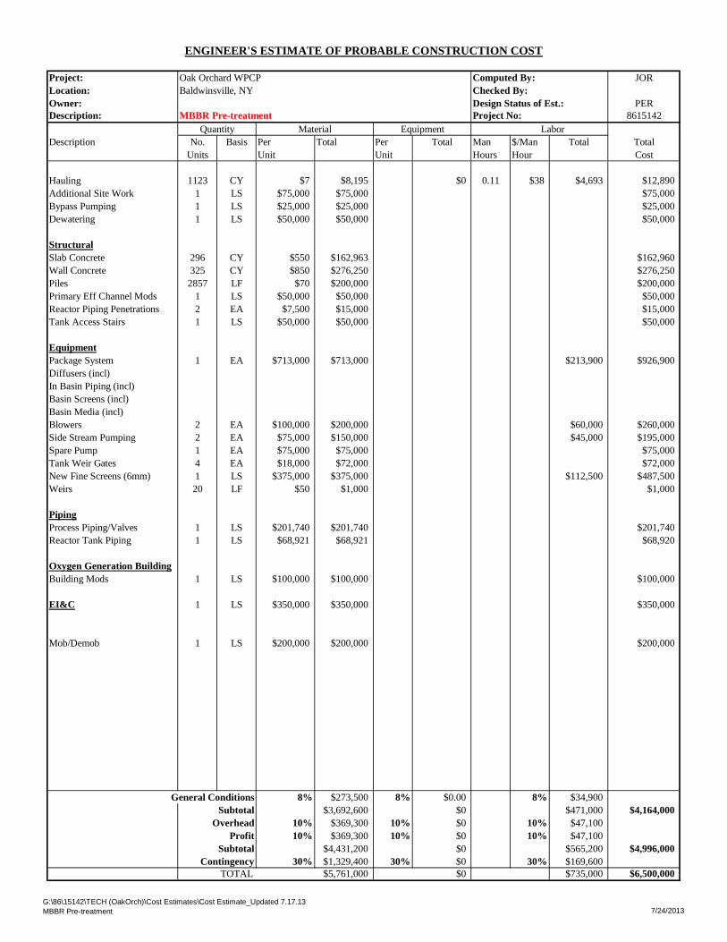
Project: Oak Orchard WPCP Computed By: JORLocation: Baldwinsville, NY Checked By:Owner: Design Status of Est.: PERDescription: MBBR Pre-treatment Project No: 8615142
Description No. Basis Per Total Per Total Man $/Man Total TotalUnits Unit Unit Hours Hour Cost
Hauling 1123 CY $7 $8,195 $0 0.11 $38 $4,693 $12,890Additional Site Work 1 LS $75,000 $75,000 $75,000Bypass Pumping 1 LS $25,000 $25,000 $25,000Dewatering 1 LS $50,000 $50,000 $50,000
StructuralSlab Concrete 296 CY $550 $162,963 $162,960Wall Concrete 325 CY $850 $276,250 $276,250Piles 2857 LF $70 $200,000 $200,000Primary Eff Channel Mods 1 LS $50,000 $50,000 $50,000Reactor Piping Penetrations 2 EA $7,500 $15,000 $15,000Tank Access Stairs 1 LS $50,000 $50,000 $50,000
EquipmentPackage System 1 EA $713,000 $713,000 $213,900 $926,900Diffusers (incl)In Basin Piping (incl)Basin Screens (incl)Basin Media (incl)Blowers 2 EA $100,000 $200,000 $60,000 $260,000Side Stream Pumping 2 EA $75,000 $150,000 $45,000 $195,000Spare Pump 1 EA $75,000 $75,000 $75,000Tank Weir Gates 4 EA $18,000 $72,000 $72,000New Fine Screens (6mm) 1 LS $375,000 $375,000 $112,500 $487,500Weirs 20 LF $50 $1,000 $1,000
PipingProcess Piping/Valves 1 LS $201,740 $201,740 $201,740Reactor Tank Piping 1 LS $68,921 $68,921 $68,920
Oxygen Generation BuildingBuilding Mods 1 LS $100,000 $100,000 $100,000
EI&C 1 LS $350,000 $350,000 $350,000
Mob/Demob 1 LS $200,000 $200,000 $200,000
General Conditions 8% $273,500 8% $0.00 8% $34,900 Subtotal $3,692,600 $0 $471,000 $4,164,000
Overhead 10% $369,300 10% $0 10% $47,100Profit 10% $369,300 10% $0 10% $47,100
Subtotal $4,431,200 $0 $565,200 $4,996,000Contingency 30% $1,329,400 30% $0 30% $169,600
TOTAL $5,761,000 $0 $735,000 $6,500,000
ENGINEER'S ESTIMATE OF PROBABLE CONSTRUCTION COST
Quantity Material Equipment Labor
G:\86\15142\TECH (OakOrch)\Cost Estimates\Cost Estimate_Updated 7.17.13MBBR Pre-treatment 7/24/2013

Project: Oak Orchard WPCP Computed By: JORLocation: Baldwinsville, NY Checked By:Owner: Design Status of Est.: PERDescription: IFAS Post-treatment Project No: 8615142
Description No. Basis Per Total Per Total Man $/Man Total TotalUnits Unit Unit Hours Hour Cost
StructuralReactor Eff Channel Mods 1 LS $100,000 $100,000 $100,000Piping Penetrations 2 EA $7,500 $15,000 $15,000Concrete Demolition 1 LS $100,000 $100,000 $100,000Concrete Repair 1 LS $100,000 $100,000 $100,000
EquipmentPackage System 1 EA $658,000 $658,000 $197,400 $855,400Diffusers (incl)In Basin Piping (incl)Basin Screens (incl)Basin Media (incl)Controls (PLC) (incl)Blowers (incl)Tank Weir Gates 4 EA $18,000 $72,000 $72,000Weirs 20 LF $50 $1,000 $1,000Existing Flocculation Demo 1 LS $50,000 $50,000 $50,000New Fine Screens (6mm) 1 LS $375,000 $375,000 $112,500 $487,500
PipingPiping 1 LS $30,000 $30,000 $30,000
Oxygen Generation BuildingBuilding Mods 1 LS $100,000 $100,000 $100,000
EI&C1 LS $350,000 $350,000 $350,000
Mob/Demob 1 LS $200,000 $200,000 $200,000
General Conditions 8% $172,100 8% $0.00 8% $24,800 Subtotal $2,323,100 $0 $334,700 $2,658,000
Overhead 10% $232,300 10% $0 10% $33,500Profit 10% $232,300 10% $0 10% $33,500
Subtotal $2,787,700 $0 $401,700 $3,189,000Contingency 30% $836,300 30% $0 30% $120,500
TOTAL $3,624,000 $0 $522,000 $4,150,000
ENGINEER'S ESTIMATE OF PROBABLE CONSTRUCTION COST
Quantity Material Equipment Labor
G:\86\15142\TECH (OakOrch)\Cost Estimates\Cost Estimate_Updated 7.17.13IFAS Post-treatment 7/24/2013

Assumptions:1. Start-up flows assumed to be current design flows2. Upgrade construction begin in Year 2014 will be completed in Year January 2016.3. O&M costs increase at annual rate of inflation of 3%.4. Present worth value of future costs estimated at 4%.
243,000.00$ O&M Cost
No. of Years YearO&M Cost in current dollars
with inflationPresent worth with annual
interest1 2016 $243,000 $243,0002 2017 $250,290 $240,6633 2018 $257,799 $238,3494 2019 $265,533 $236,0585 2020 $273,499 $233,7886 2021 $281,704 $231,5407 2022 $290,155 $229,3138 2023 $298,859 $227,1099 2024 $307,825 $224,925
10 2025 $317,060 $222,76211 2026 $326,572 $220,62012 2027 $336,369 $218,49913 2028 $346,460 $216,39814 2029 $356,854 $214,31715 2030 $367,559 $212,25616 2031 $378,586 $210,21517 2032 $389,944 $208,19418 2033 $401,642 $206,19219 2034 $413,691 $204,21020 2035 $426,102 $202,246
TOTAL (20 Yr. PW ): $4,400,000
Oak Orchard Magnetite Ballasted Settling
G:\86\15142\TECH (OakOrch)\Cost Estimates\Cost Estimate_Updated 7.17.13BioMag O&M Summary 5 of 13 7/24/2013

ENGINEER'S ESTIMATE OF PROBABLE OPERATIONS AND MAINTENANCE COST
Project: Oak Orchard WPCP Computed By: JORLocation: Baldwinsville, NY Checked By:Owner: Design Status of Est.: PrelimDescription: Biomag O&M Costs Project No: 8614629
Objective: Calculate Annual O&M Cost at design capacity of 5.3 mgd after upgrade is completed.
Assumptions: Electrical Cost per KWH: $0.10 Estimated Electrical CostAdditional Employee: 0
Operations Labor Costs:
Maint. Costs:New Equipment:
Biomag Equipment Costs $2,500,000 May 2013 Proposal
Total Equipment Cost $2,500,000Maintenance Cost/Year: $50,000 2% of equipment cost
Total Maintenance Cost/Year: $50,000
Materials CostsMagnetite Recovery per year 237,250.0 650 lbs/d
Annual Cost: $94,900
Power RequirementsPower Requirement (kW-hr) 981,469 From electric spreadsheet tab
$98,147Annual Cost Summary:
RoundedAnnual Additional Operation Labor Cost: $0 $0
Annual Maintenance Cost: $50,000 $50,000Annual Materials Cost: $94,900 $94,900
Annual Power Requirements: $98,147 $98,100Total Annual O & M Cost @ Rated Capacity: $243,047 $243,000
G:\86\15142\TECH (OakOrch)\Cost Estimates\Cost Estimate_Updated 7.17.13 Cost Estimate_Updated 7.17.13

Oak Orchard 7/22/13 8614629Client Date Job No.
BIOMAG Electrical Cost Estimates JORSubject Comp. By Chkd By
ELECTRICAL USAGE
Objective:Determine the power usage at a design average day flow of 5.3 mgdDesign criteria for piece of equipment is summarized in the table below.Some power usage supplied by vendors as noted
For Pumps:Pump horsepower determined with the following equation unless specified by a proposal: HP = Q(gpm) x THD (ft) / 3956 x (eff%)
Power Cost ($/kW/hr) $0.10
Equipment Units Operating at average flow
(5.3 mgd)
Operating Capacity (per unit)
Operating TDH or
Discharge Pressure
Efficiency @ Operating Duty Point
Total Brake Horsepower
Total Nameplate Horsepower
Input Power per
Unit Average
Conditions (kW)
Total Input Power
Average Conditions
(kW)
Hours of Operation per Day
Days of Operation Per Week
Power Consumed per Year kW*hr
Power Cost per
Year
Magnetic Drum Seperator 3 7 3.1332 9.3996 24 7 82,115 $8,211Shear Mill 3 50 18.65 55.95 24 7 488,779 $48,878Ballast Tank Mixers 1 3 2.238 2.238 24 7 19,551 $1,955Ballast System Compressor 1 20 7.46 7.46 24 7 65,171 $6,517BioMag BRAS Return Pumps 1 10 7.46 7.46 24 7 65,171 $6,517Aerobic Mixers 3 10 7.46 22.38 24 7 195,512 $19,551BioMag WAS Pumps 1 10 7.46 7.46 24 7 65,171 $6,517
Annual Power Consumption 981,469Total Annual Power Cost $98,147
G:\86\15142\TECH (OakOrch)\Cost Estimates\Cost Estimate_Updated 7.17.13BioMag O&M Electrical7/24/2013

Assumptions:1. Start-up flows assumed to be current design flows2. Upgrade construction begin in Year 2014 will be completed in Year January 2016.3. O&M costs increase at annual rate of inflation of 3%.4. Present worth value of future costs estimated at 4%.
247,000.00$ O&M Cost
No. of Years YearO&M Cost in current dollars with
inflationPresent worth with annual
interest1 2016 $247,000 $247,0002 2017 $254,410 $244,6253 2018 $262,042 $242,2734 2019 $269,904 $239,9435 2020 $278,001 $237,6366 2021 $286,341 $235,3517 2022 $294,931 $233,0888 2023 $303,779 $230,8479 2024 $312,892 $228,627
10 2025 $322,279 $226,42911 2026 $331,947 $224,25212 2027 $341,906 $222,09513 2028 $352,163 $219,96014 2029 $362,728 $217,84515 2030 $373,610 $215,75016 2031 $384,818 $213,67617 2032 $396,362 $211,62118 2033 $408,253 $209,58619 2034 $420,501 $207,57120 2035 $433,116 $205,575
TOTAL (20 Yr. PW ): $4,500,000
Oak OrchardMBBR
G:\86\15142\TECH (OakOrch)\Cost Estimates\Cost Estimate_Updated 7.17.13MBBR O&M Summary 8 of 13 7/24/2013

ENGINEER'S ESTIMATE OF PROBABLE OPERATIONS AND MAINTENANCE COST
Project: Oak Orchard WPCP Computed By: JORLocation: Baldwinsville, NY Checked By:Owner: Design Status of Est.: PrelimDescription: MBBR O&M Costs Project No: 8614629
Objective: Calculate Annual O&M Cost at design capacity of 5.3 mgd after upgrade is completed.
Assumptions: Electrical Cost per KWH: $0.10 Estimated Electrical CostAdditional Employee: 0
Operations Labor Costs:
Maint. Costs:New Equipment:
MBBR Equipment Costs $1,063,000 June 21, 2013 Proposal
Total Equipment Cost $1,063,000Maintenance Cost/Year: $21,260 2% of equipment cost
Total Maintenance Cost/Year: $21,260
Materials Costs10,630.0 Additional Media
Annual Cost: $10,630
Power RequirementsPower Requirement (kW-hr) 2,150,628 From electric spreadsheet tab
$215,063 From electric spreadsheet tabAnnual Cost Summary:
RoundedAnnual Additional Operation Labor Cost: $0 $0
Annual Maintenance Cost: $21,260 $21,300Annual Materials Cost: $10,630 $10,630
Annual Power Requirements: $215,063 $215,100Total Annual O & M Cost @ Rated Capacity: $246,953 $247,000
G:\86\15142\TECH (OakOrch)\Cost Estimates\Cost Estimate_Updated 7.17.13 Cost Estimate_Updated 7.17.13

Oak Orchard 7/22/13 8614629Client Date Job No.
MBBR Electrical Cost Estimates - JORSubject Comp. By Chkd By
ELECTRICAL USAGE
Objective:Determine the power usage at a design average day flow of 5.3 mgdDesign criteria for piece of equipment is summarized in the table below.Some power usage supplied by vendors as noted
For Pumps:Pump horsepower determined with the following equation unless specified by a proposal: HP = Q(gpm) x THD (ft) / 3956 x (eff%)
Power Cost ($/kW/hr) $0.10
Equipment Units Operating at average flow
Operating Capacity (per unit)
Operating TDH or
Discharge Pressure
Efficiency @ Operating Duty Point
Total Brake Horsepower
Total Nameplate Horsepower
Input Power per
Unit Average
Conditions (kW)
Total Input Power
Average Conditions
(kW)
Hours of Operation per Day
Days of Operation Per Week
Power Consumed per Year kW*hr
Power Cost per
Year
Blowers 2 125 93.25 186.5 24 7 1,629,264 $162,926Lift Pumps 2 3,500 25 80% 17.7 40 29.84 59.68 24 7 521,364 $52,136
Annual Power Consumption 2,150,628Total Annual Power Cost $215,063
G:\86\15142\TECH (OakOrch)\Cost Estimates\Cost Estimate_Updated 7.17.13MBBR O&M Electrical7/24/2013

Assumptions:1. Start-up flows assumed to be current design flows2. Upgrade construction begin in Year 2014 will be completed in Year January 2016.3. O&M costs increase at annual rate of inflation of 3%.4. Present worth value of future costs estimated at 4%.
120,100.00$ O&M Cost
No. of Years YearO&M Cost in current dollars
with inflation Present worth with annual interest1 2016 $120,100 $120,1002 2017 $123,703 $118,9453 2018 $127,414 $117,8014 2019 $131,237 $116,6695 2020 $135,174 $115,5476 2021 $139,229 $114,4367 2022 $143,406 $113,3368 2023 $147,708 $112,2469 2024 $152,139 $111,167
10 2025 $156,703 $110,09811 2026 $161,404 $109,03912 2027 $166,246 $107,99113 2028 $171,234 $106,95214 2029 $176,371 $105,92415 2030 $181,662 $104,90516 2031 $187,112 $103,89717 2032 $192,725 $102,89818 2033 $198,507 $101,90819 2034 $204,462 $100,92820 2035 $210,596 $99,958
TOTAL (20 Yr. PW ): $2,200,000
Oak OrchardIFAS Post-treatment
G:\86\15142\TECH (OakOrch)\Cost Estimates\Cost Estimate_Updated 7.17.13IFAS O&M Summary 11 of 13 7/24/2013

ENGINEER'S ESTIMATE OF PROBABLE OPERATIONS AND MAINTENANCE COST
Project: Oak Orchard WPCP Computed By: JORLocation: Baldwinsville, NY Checked By:Owner: Design Status of Est.: PrelimDescription: IFAS O&M Costs Project No: 8614629
Objective: Calculate Annual O&M Cost at design capacity of 5.3 mgd after upgrade is completed.
Assumptions: Electrical Cost per KWH: $0.10 Estimated Electrical CostAdditional Employee: 0
Operations Labor Costs:
Maint. Costs:New Equipment:
Equipment Costs $658,000 June 21, 2013 Proposal
Total Equipment Cost $658,000Maintenance Cost/Year: $13,160 2% of equipment cost
Total Maintenance Cost/Year: $13,160
Materials Costs6,580.0 Media
Annual Cost: $2,632
Power RequirementsPower Requirement (kW-hr) 1,042,729 From electric spreadsheet tab
$104,273Annual Cost Summary:
RoundedAnnual Additional Operation Labor Cost: $0 $0
Annual Maintenance Cost: $13,160 $13,200Annual Materials Cost: $2,632 $2,632
Annual Power Requirements: $104,273 $104,300Total Annual O & M Cost @ Rated Capacity: $120,065 $120,100
G:\86\15142\TECH (OakOrch)\Cost Estimates\Cost Estimate_Updated 7.17.13 Cost Estimate_Updated 7.17.13

Oak Orchard 4/25/11 8614629Client Date Job No.
IFAS Electrical Cost Estimates JORSubject Comp. By Chkd By
ELECTRICAL USAGE
Objective:Determine the power usage at a design average day flow of 5.3 mgdDesign criteria for piece of equipment is summarized in the table below.Some power usage supplied by vendors as noted
For Pumps:Pump horsepower determined with the following equation unless specified by a proposal: HP = Q(gpm) x THD (ft) / 3956 x (eff%)
Power Cost ($/kW/hr) $0.10
Equipment Units Operating at average flow
Operating Capacity (per unit)
Operating TDH or
Discharge Pressure
Efficiency @ Operating Duty Point
Total Brake Horsepower
Total Nameplate Horsepower
Input Power per
Unit Average
Conditions (kW)
Total Input Power
Average Conditions
(kW)
Hours of Operation per Day
Days of Operation Per Week
Power Consumed per Year kW*hr
Power Cost per
Year
Blowers 1 150 111.9 111.9 24 7 977,558 $97,756Blowers 1 10 7.46 7.46 24 7 65,171 $6,517
Annual Power Consumption 1,042,729Total Annual Power Cost $104,273
G:\86\15142\TECH (OakOrch)\Cost Estimates\Cost Estimate_Updated 7.17.13IFAS O&M Electrical7/24/2013

GHD Consulting Services Inc.
One Remington Park Drive Cazenovia, NY 13035
T: (315) 679-5800 F: (315) 679-5801 E: www.ghd.com
© GHD Inc 2013
This document is and shall remain the property of GHD. The document may only be used for the purpose of assessing our offer of services and for inclusion in documentation for the engagement of GHD. Unauthorized use of this document in any form whatsoever is prohibited.
Document Status
Rev No. Author
Reviewer Approved for Issue Name Signature Name Signature Date

www.ghd.com