ono l - seafix.com.br · as correntes devem ser retiradas de serviÇo (descartadas), quando: (1)...
TRANSCRIPT
AÇ
OG
RA
U8 +
AÇ
O C
AR
BO
NO
GR
AD
E 8
STE
EL &
CA
RB
ON
STE
EL
Correntes
Destorcedor Galvanizado
Elo de Ligação
Esticador Gxo
Ganchos
Grampos
Lingas de Corrente
Manilhas
Olhais de Suspensão
Pega Chapas
Pega Vigas
Sapatilhas
Tensionador de Corrente
Chains
Galvanized Swivel
Connecting Link
Turnbuckle Hxe
Hooks
Clips
Lifting Chain Sling
Shackles
Lifting Eyes
Plate Clamps
Beam Clamps
Thimbles
Ratchet Load Binder

INSPEÇÃO EM CORENTES DE ELOS SOLDADOS (Grau 8)Produtos fabricados em aço Grau 8, possuem grande resistência mecânica e elevado desempenho em aplicações dinâmicas.Porém, também estão sujeitos à desgaste por fadiga.A fadiga é um fenômeno mecânico, natural a todos os tipos de aço, causado em decorrência do tempo de utilização e do número deciclos de trabalho à qual o material é submetido.A fadiga faz com que o material perca sua resistência mecânica, causando deformações, alongamento e posterior ruptura.
AS CORRENTES DEVEM SER RETIRADAS DE SERVIÇO (DESCARTADAS), QUANDO:(1) Apresentarem deformação por dobra, torção, amassamento ou entalhamento;(2) Apresentarem alongamento de mais de 5% no comprimento no passo da corrente, o que caracterizaria que a corrente sofreuuma deformação plástica (permanente) e / ou desgaste no diâmetro, por atrito.(3) Apresentarem, em qualquer ponto de sua extensão, redução igual ou superior a 10% no seu diâmetro médio.
LIFTING CHAIN (Grade 8) INSPECTIONProducts made of Grade 8 steel,have high mechanical strength and high performance in dynamic applications. However, are also subject to wear fatigue.The fatigue is a mechanical phenomenon natural to all types of steel, caused due to the usage time and the number of working cycles which the materialissubjected.Fatigue causes the material to lose its mechanical strength, causing deformation, elongation and subsequent rupture.
THE CHAINS MUST BE REMOVED FROM SERVICE (DISCARDED) WHEN:(1) show deformation by bending, twisting, kneading or notching;(2) Show elongation bigger than 5% at pitch of the chain, it can be caused by plastic elongation (overload) and / or wear diameter by friction.(3) show, at any point on its length, diameter reduction of 10% or more.
EXPOSIÇÃO A ALTAS TEMPERATURAS REDUZEM A CARGA DE TRABALHO DA CORRENTE:
Temperatura:
Entre -40°C e 200°C - Não há alteração na Carga Máxima de Trabalho. / Between -40°C and 200°C - No change in WLL.
Entre 200°C e 300°C - Redução de 10% na Carga Máxima de Trabalho. / Between 200°C and 300°C -10% reduction in the WLL.
Entre 300°C e 400°C - Redução de 25% na Carga Máxima de Trabalho. / Between 300°C and 400°C -25% reduction in WLL.
EXPOSIÇÃO A CANTOS VIVOS REDUZ A CARGA DE TRABALHO DA CORRENTESempre que possível, devemos evitar os cantos vivos. Porém, se isso não for possível, devemos utilizar a corrente, levando emconsideração que sua Carga Máxima de Trabalho sofrerá uma redução de até 50%Para o uso de correntes, considera-se canto vivo, quando o raio da peça é menor que 2 x o diâmetro nominal da corrente.
HIGH TEMPERATURE EXPOSURE REDUCES THE WORK LOAD LIMIT VALUE.
Temperature:
Relação entre Diâmetro daCorrente e Raio do canto
Redução do Valor daCarga Máxima de Trabalho
Raio 2 x Diâmetro da CorrenteRaio Diâmetro da CorrenteRaio Diâmetro da Corrente
>
<
≥ 0%30%50%
Radius 2 x Chain DiameterRadius Chain DiameterRadius Chain Diameter
≥
>
<
0%30%50%
Relation between Chain Diameter& Corner Radius WorkLoad Limit Reduction
Nota: em caso de dúvida, contate nosso departamento técnico.
EXPOSURE TO SHARP CORNERS MAY REDUCES THE WORKLOAD LIMIT VALUEWhenever possible, we must avoid sharp corners. But if not possible, we shall use the chain, assuming that your work load limit will be reduced up to 50%.For chains, it is considered sharp corner when the corner radius is smaller than 2 x chain diameter.
NOTE: In case of doubt, call our technical department.
20T: 55 21 3866-0231T: 55 21 3866-0159
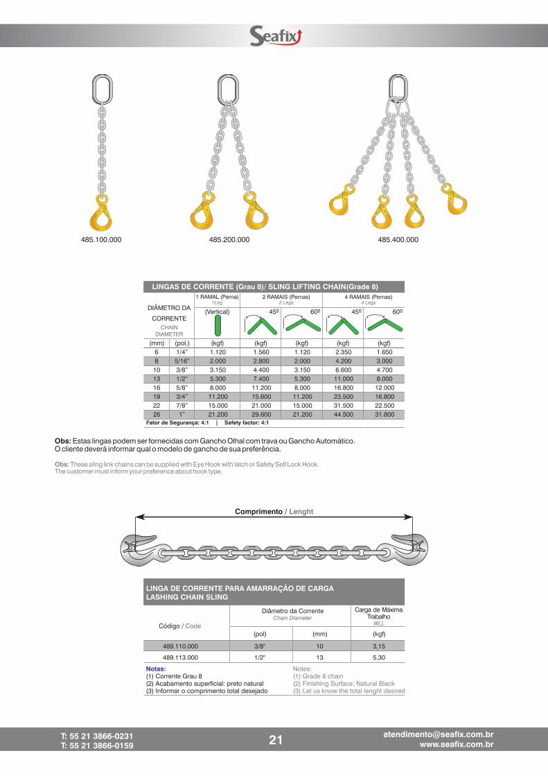
485.100.000 485.200.000 485.400.000
Obs: Estas lingas podem ser fornecidas com Gancho Olhal com trava ou Gancho Automático.O cliente deverá informar qual o modelo de gancho de sua preferência.
Obs: These sling link chains can be supplied with Eye Hook with latch or Safety Self Lock Hook.The customer must inform your preference about hook type.
LINGAS DE CORRENTE (Grau 8)/ SLING LIFTING CHAIN(Grade 8)
Comprimento / Lenght
DIÂMETRO DA
CORRENTE
1 RAMAL (Perna)1Leg
2 RAMAIS (Pernas)2 Legs
4 RAMAIS (Pernas)4 Legs
(Vertical) 45º 60º 45º 60º
(mm) (pol.) (kgf) (kgf) (kgf) (kgf) (kgf)6 1/4” 1.120 1.560 1.120 2.350 1.6508 5/16” 2.000 2.800 2.000 4.200 3.00010 3/8” 3.150 4.400 3.150 6.600 4.70013 1/2” 5.300 7.400 5.300 11.000 8.00016 5/8” 8.000 11.200 8.000 16.800 12.00019 3/4” 11.200 15.600 11.200 23.500 16.80022 7/8” 15.000 21.000 15.000 31.500 22.50026 1” 21.200 29.600 21.200 44.500 31.800
Fator de Segurança: 4:1 | Safety factor: 4:1
CHAINDIAMETER
LINGA DE CORRENTE PARA AMARRAÇÃO DE CARGALASHING CHAIN SLING
(pol) (mm) (kgf)
489.110.000 3/8" 10 3,15
489.113.000 1/2" 13 5,30
Notas:(1) Corrente Grau 8(2) Acabamento superficial: preto natural(3) Informar o comprimento total desejado
Carga de MáximaTrabalho
Diâmetro da Corrente
WLLChain Diameter
Código / Code
Notes:(1) Grade 8 chain(2) Finishing Surface: Natural Black(3) Let us know the total lenght desired
21T: 55 21 3866-0231T: 55 21 3866-0159
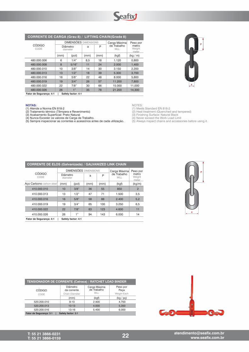
NOTES:(1) Meets Standard EN 818-2(2) Heat treatment (Quenched and tempered)(3) Finishing Surface: Natural Black(4) Never exceed the Work Load Limit(5) Always inspect chains and accessories before using it.
NOTAS:(1) Atende a Norma EN 818-2(2) Tratamento térmico (Têmpera e Revenimento)(3) Acabamento Superficial: Preto Natural(4) Nunca Exceder os valores de Carga de Trabalho.(5) Sempre inspecionar as correntes e acessórios antes de cada utilização.
(mm) (pol) (mm) (mm) (kgf) (kg / m)
480.000.006 6 1/4” 8,5 18 1.120 0,800480.000.008 8 5/16” 11 24 2.000 1,400480.000.010 10 3/8” 14 30 3.150 2,200480.000.013 13 1/2” 18 39 5.300 3,700480.000.016 16 5/8” 22 48 8.000 5,800480.000.019 19 3/4” 26 57 11.200 7,800480.000.022 22 7/8” 30 66 15.000 11,000480.000.026 26 1” 35 78 21.200 14,300
CÓDIGODIMENSÕES Carga Máxima
de TrabalhoPeso por
metroDiâmetro a PCODE
DIMENSIONS
WLL Weightmeter
diameter
Fator de Segurança: 4:1 | Safety factor: 4:1
CORRENTE DE CARGA (Grau 8) / LIFTING CHAIN(Grade 8)
a P
Aço Carbono (mm) (pol) (mm) (mm) (kgf) (kg/m)
410.000.010 10 3/8” 36 55 850 2
410.000.013 13 1/2” 47 71 1.500 3,5
410.000.016 16 5/8” 58 88 2.400 5,2
410.000.019 19 3/4” 65 100 3.250 6,5
410.000.022 22 7/8” 83 123 4.600 11
410.000.026 26 1” 94 143 6.000 14
CÓDIGODIMENSÕES Peso por
metroDiâmetroCODE
DIMENSIONS
Weightmeter
diameter
carbon steel
Fator de Segurança: 4:1 | Safety factor: 4:1
Carga Máximade Trabalho
WLL
CORRENTE DE ELOS (Galvanizada) / GALVANIZED LINK CHAIN
CÓDIGODiâmetro
da correntePeso por
Peça
(mm) (kgf) (kg / pç)520.200.010 8-10 2.400 4,700520.200.013 10-13 4.000 5,350520.200.016 13-16 5.400 6,000
CODE Chain Diameter Weight Each
Fator de Segurança: 3:1 | Safety factor: 3:1
Carga Máximade Trabalho
WLL
TENSIONADOR DE CORRENTE (Catraca) / RATCHET LOAD BINDER
22T: 55 21 3866-0231T: 55 21 3866-0159

NOTAS:É a solução ideal para ancoragem/fixação de talhas e guinchosem vigas. De fácil utilização, possui largura ajustável e pode serutilizado em vários tipo de viga de aço.
PEGA VIGA / BEAM CLAMP
A
(mm) (kgf) (kg / pç)
555.100.001 75 - 230 1.000 4,300
555.100.002 75 - 230 2.000 5,000
555.100.003 80 - 320 3.000 9,200
555.100.005 90 - 320 5.000 10,000
555.100.010 90 - 320 10.000 16,000
Fator de Segurança: 4:1 | Safety factor: 4:1
Carga de MáximaTrabalho Peso por Peça
WLLWeight Each
Código / Code
NOTAS:Fabricado em aço Grau 8, com base soldável. Permite aarticulação em até 180º.A solução ideal para equipamentos e estruturas metálicas quenecessitam de ponto de içamento permanente.Apresenta excelente resultado como ponto de amarração decargas em implementos rodoviários, ferroviários e marítimos.Possui Fator de Segurança 4:1.
Carga de Máxima TrabalhoPeso por
Peça
WLL
Weight EachCódigo / Code
DimensõesDimensions
23T: 55 21 3866-0231T: 55 21 3866-0159
NOTES:The best solution for anchoring / fixing hoists at beams. Easy to use, hasadjustable width and can be used in various type of steel beam.
Notes:Manufactured of grade 8 steel, with weldable base. Allows the joint up to180 degrees.The ideal solution for equipment and metal structures that requirepermanent lifting point.It presents excellent results as charges mooring on road, rail and
maritime implements.
OLHAL DE SUSPENSÃO ARTICULADO (Grau 8)WELDABLE LIFTING POINT (Grade 8)
0,400
0,700
1,500
2,500
5,900
Ajustável 180°Adjustable 180
D
w
A
C
B
d
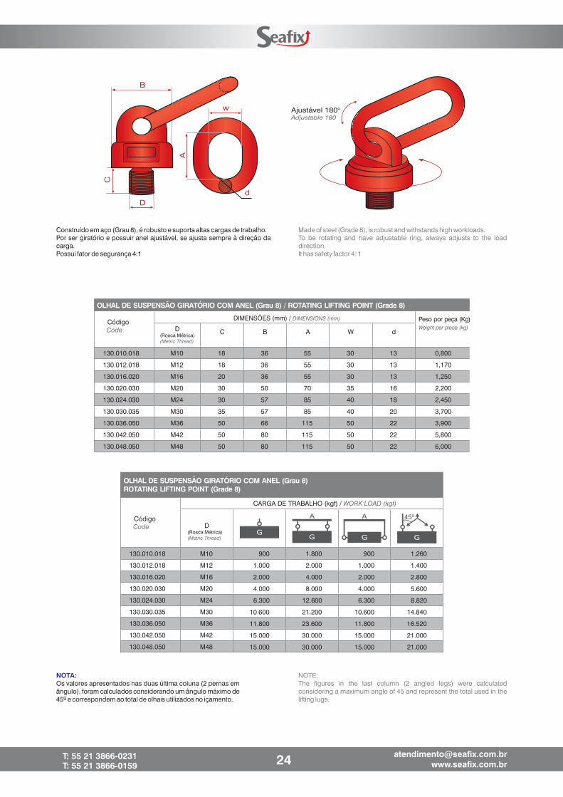
Construído em aço (Grau 8), é robusto e suporta altas cargas de trabalho.Por ser giratório e possuir anel ajustável, se ajusta sempre à direção dacarga.Possui fator de segurança 4:1
Made of steel (Grade 8), is robust and withstands high workloads.To be rotating and have adjustable ring, always adjusts to the loaddirection.It has safety factor 4: 1
NOTA:Os valores apresentados nas duas última coluna (2 pernas emângulo), foram calculados considerando um ângulo máximo de45º e correspondem ao total de olhais utilizados no içamento.
NOTE:The figures in the last column (2 angled legs) were calculatedconsidering a maximum angle of 45 and represent the total used in thelifting lugs.
Peso por peça (Kg)
D C B A W d
130.010.018 M10 18 36 55 30 13 0,800
130.012.018 M12 18 36 55 30 13 1,170
130.016.020 M16 20 36 55 30 13 1,250
130.020.030 M20 30 50 70 35 16 2,200
130.024.030 M24 30 57 85 40 18 2,450
130.030.035 M30 35 57 85 40 20 3,700
130.036.050 M36 50 66 115 50 22 3,900
130.042.050 M42 50 80 115 50 22 5,800
130.048.050 M48 50 80 115 50 22 6,000
OLHAL DE SUSPENSÃO GIRATÓRIO COM ANEL (Grau 8) / ROTATING LIFTING POINT (Grade 8)
CódigoCode
(Rosca Métrica)(Metric Thread)
DIMENSÕES (mm) / DIMENSIONS (mm)
Weight per piece (kg)
24T: 55 21 3866-0231T: 55 21 3866-0159
OLHAL DE SUSPENSÃO GIRATÓRIO COM ANEL (Grau 8)ROTATING LIFTING POINT (Grade 8)
CódigoCode
CARGA DE TRABALHO (kgf) / WORK LOAD (kgf)
D(Rosca Métrica)(Metric Thread)
130.010.018 M10
130.012.018 M12
130.016.020 M16
130.020.030 M20
130.024.030 M24
130.030.035 M30
130.036.050 M36
130.042.050 M42
130.048.050 M48
45º
1.260
1.400
2.800
5.600
8.820
14.840
16.520
21.000
21.000
900
1.000
4.000
6.300
10.600
11.800
15.000
15.000
2.000
1.800
2.000
4.000
8.000
12.600
21.200
23.600
30.000
30.000
900
1.000
2.000
4.000
6.300
10.600
11.800
15.000
15.000
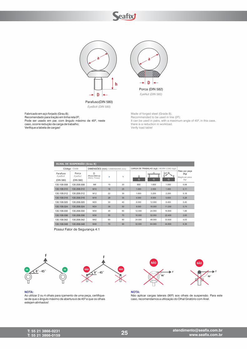
Fabricado em aço forjado (Grau 8);Recomendado para tração em linha reta 0º;Pode ser usado em par, com ângulo máximo de 45º, nestecaso, ocorre redução da carga de trabalho;Verifique a tabela de cargas!
NOTA:Não aplicar cargas laterais (90º) aos olhais de suspensão. Para estecaso, recomendamos a utilização do Olhal Giratório com Anel.
NOTA:Ao utilizar 2 ou 4 olhais para içamento de uma peça, certifique-se de que o ângulo máximo de abertura é de 45º e que os olhaisestejam alinhados!
25T: 55 21 3866-0231T: 55 21 3866-0159
Parafuso(DIN 580)
Porca (DIN 582)
EyeBolt (DIN 580)
EyeNut (DIN 582)
Made of forged steel (Grade 8);Recommended to be used in line (0º);It can be used in pairs, with a maximum angle of 45º, in this case,there is a reduction in workload.Verify load table!
Peso por peça(Kg)D
Código Code
(Rosca Métrica)(Metric Thread)
DIMENSÕES (mm) / DIMENSIONS (mm)
Weight per piece
(kg)
Possui Fator de Segurança 4:1
ParafusoEyeBolt
(DIN 580)
130.108.008
130.108.010
130.108.012
130.108.016
130.108.020
130.108.024
130.108.030
130.108.036
130.108.042
130.108.048
130.208.008
130.208.010
130.208.012
130.208.016
130.208.020
130.208.024
130.208.030
130.208.036
130.208.042
130.208.048
(DIN 582)
EyeNutPorca 45º
CARGA DE TRABALHO (kgf) / WORK LOAD (kgf)
GANCHO OLHAL AUTOMÁTICO (Grau 8)SAFETY SELF LOCK HOOK (Grade 8)
CódigoCode
DIMENSÕES / DIMENSIONS CargaMáxima deTrabalho
Peso porPeçaDiâmetro
da correnteL a b c h
(mm) (pol) (mm) (mm) (mm) (mm) (mm) (kgf) (kg / pç)
140.208.006 6 1/4” 15 29 22 21 130 1.120 0,500
140.208.008 8 5/16” 17 37 28 25 162 2.000 0,900
140.208.010 10 3/8” 21 44 34 30 198 3.150 1,500
140.208.013 13 1/2” 30 54 44 39 246 5.300 3,000
140.208.016 16 5/8” 37 62 56 49 302 8.000 5,500
140.208.019 19 3/4” 42 68 60 62 354 11.200 9,000
140.208.022 22 7/8” 47 80 70 64 382 15.000 11,300
140.208.026 26 1” 50 100 80 68 423 21.200 16,500Fator de Segurança: 4:1 | Safety factor: 4:1
Chaim
DiameterWLL
Weight
Each
b
c
L
h
GANCHO CLÉVIS ENCURTADOR (Grau 8) / CLEVIS GRAB HOOK (Grade 8)
Código / Code Diâmetro da corrente h b
(mm) (pol) (mm) (mm) (kgf) (kg / pç)
140.708.006 6 1/4” 45 8 1.120 0,250140.708.008 8 5/16” 58 10 2.000 0,320140.708.010 10 3/8” 77 13 3.150 0,760140.708.013 13 1/2” 97 16 5.300 1,650140.708.016 16 5/8” 124 18 8.000 2,800
Fator de Segurança: 4:1 | Safety factor: 4:1
Current Diameter
DIMENSÕES / DIMENSIONS Carga de MáximaTrabalho Peso por Peça
WLLWeight Each
a
h
D
h1
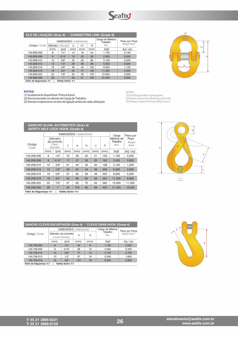
ELO DE LIGAÇÃO (Grau 8) / CONNECTING LINK (Grade 8)
Diâmetro / Diameter a h1 H(mm) (pol) (mm) (mm) (mm) (kgf) (kg / pç)
140.808.006 6 1/4” 15 16 44 1.120 0,100
140.808.008 8 5/16” 18 22 56 2.000 0,200
140.808.010 10 3/8” 25 26 68 3.150 0,320140.808.013 13 1/2” 29 36 89 5.300 0,640140.808.016 16 5/8” 36 40 105 8.000 1,120140.808.019 19 3/4” 43 47 125 11.200 2,000140.808.022 22 7/8” 50 59 152 15.000 3,000140.808.026 26 1” 58 61 160 21.200 5,200
Fator de Segurança: 4:1 | Safety factor: 4:1
Código / Code
DIMENSÕES / DIMENSIONSCarga de Máxima
Trabalho Peso por Peça
WLLWeight Each
NOTAS:(1) Acabamento Superficial: Pintura Epóxi.(2) Nunca exceder os valores de Carga de Trabalho.(3) Sempre inspecionar os elos de ligação antes de cada utilização.
NOTES:
(1) Finishing Surface: Epoxy paint.
(2) Never exceed the Working Load Limit.
(3) Always inspect the links before use it.
26T: 55 21 3866-0231T: 55 21 3866-0159
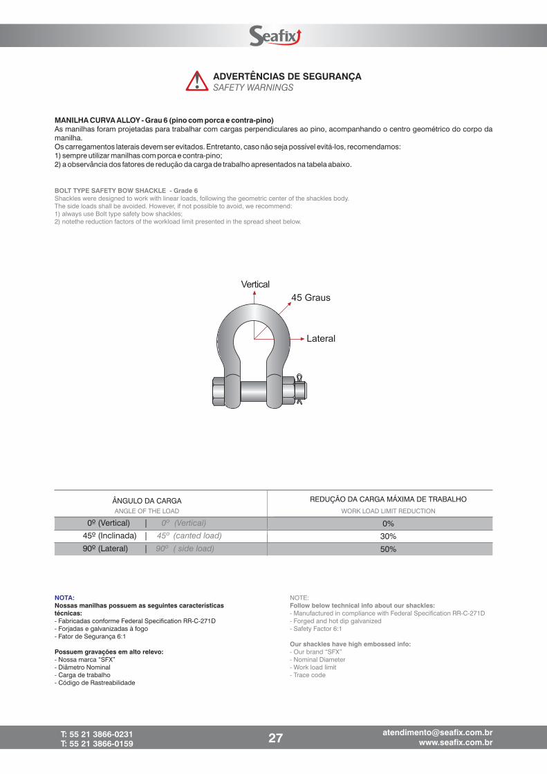
Vertical
45 Graus
Lateral
MANILHA CURVA ALLOY - Grau 6 (pino com porca e contra-pino)As manilhas foram projetadas para trabalhar com cargas perpendiculares ao pino, acompanhando o centro geométrico do corpo damanilha.Os carregamentos laterais devem ser evitados. Entretanto, caso não seja possível evitá-los, recomendamos:1) sempre utilizar manilhas com porca e contra-pino;2) a observância dos fatores de redução da carga de trabalho apresentados na tabela abaixo.
BOLT TYPE SAFETY BOW SHACKLE - Grade 6Shackles were designed to work with linear loads, following the geometric center of the shackles body.The side loads shall be avoided. However, if not possible to avoid, we recommend:1) always use Bolt type safety bow shackles;2) notethe reduction factors of the workload limit presented in the spread sheet below.
ADVERTÊNCIAS DE SEGURANÇASAFETY WARNINGS
ÂNGULO DA CARGAANGLE OF THE LOAD
0º (Vertical) | 0º (Vertical)
45º (Inclinada) | 45º (canted load)
90º (Lateral) | 90º ( side load)
REDUÇÃO DA CARGA MÁXIMA DE TRABALHO
WORK LOAD LIMIT REDUCTION
0%
30%
50%
27T: 55 21 3866-0231T: 55 21 3866-0159
NOTE:
- Manufactured in compliance with Federal Specification RR-C-271D- Forged and hot dip galvanized- Safety Factor 6:1
- Our brand “SFX”- Nominal Diameter- Work load limit- Trace code
Follow below technical info about our shackles:
Our shackles have high embossed info:
NOTA:
- Fabricadas conforme Federal Specification RR-C-271D- Forjadas e galvanizadas à fogo- Fator de Segurança 6:1
- Nossa marca “SFX”- Diâmetro Nominal- Carga de trabalho- Código de Rastreabilidade
Nossas manilhas possuem as seguintes característicastécnicas:
Possuem gravações em alto relevo:

D
d2
a
h
b
D
d2
a
h
Diâmetro / DiameterCódigoCode
DIMENSÕES / DIMENSIONS
110.208.008 8 5/16” 13 21 32 10 750 0,0800,1300,3000,6000,8901,5402,1904,4207,780
110.208.010 10 3/8” 17 27 38 12 1.000110.208.013 13 1/2” 21 33 51 16 2.000110.208.016 16 5/8” 27 42 60 19 3.250
110.208.019 19 3/4” 32 51 73 22 4.750110.208.022 22 7/8” 36 58 83 25 6.500110.208.026 26 1” 43 68 92 29 8.500110.208.032 32 1.1/4” 52 82 121 35 12.000110.208.038 38 1.1/2” 60 92 140 41 17.000Fator de Segurança: 6:1 | Safety factor: 6:1
a b h d2
(mm) (pol) (mm) (mm) (mm) (mm) (kgf) (kg / pç)
MANILHA CURVA ALLOY – Grau 6 (Pino roscado)
SCREW PIN BOW SHACKLE ALLOY - Grade 6Carga de
Máxima TrabalhoPeso por
PeçaWLL Weight Each
a b h d2
(mm) (pol) (mm) (mm) (mm) (mm) (kgf) (kg / pç)
Diâmetro / DiameterCódigoCode
DIMENSÕES / DIMENSIONS
MANILHA CURVA ALLOY – Grau 6 (Pino com porca e contra-pino)
110.218.008 8 5/16” 13 21 32 10 750 0,100110.218.010 10 3/8” 17 27 38 12 1.000 0,170110.218.013 13 1/2” 21 33 51 16 2.000 0,340110.218.016 16 5/8” 27 42 60 19 3.250 0,670110.218.019 19 3/4” 32 51 73 22 4.750 1,080110.218.022 22 7/8” 36 58 83 25 6.500 1,590110.218.026 26 1” 43 68 92 29 8.500 2,390110.218.029 29 1.1/8” 46 73 108 32 9.500 3,750110.218.032 32 1.1/4” 52 82 121 35 12.000 4,860110.218.035 35 1.3/8” 57 92 133 38 13.500 7,180
110.218.038 38 1.1/2” 60 92 140 41 17.000 8,560110.218.045 45 1.3/4” 73 127 178 51 25.000 15,400110.218.050 50 2” 82 146 197 57 35.000 23,700110.218.065 65 2.1/2” 105 184 267 70 55.000 44,600
Fator de Segurança: 6:1 | Safety factor: 6:1
BOLT TYPE SAFETY BOW SHACKLE ALLOY - Grade 6Carga de
Máxima TrabalhoPeso por
Peça
WLL Weight Each
MANILHA RETA ALLOY – Grau 6 (Pino roscado)
a h d2
(mm) (pol) (mm) (mm) (mm) (kgf) (kg / pç)
110.108.008 8 5/16” 13 26 10 750 0,070
0,125
0,270
0,520
0,900
1,400
2,050
4,110
7,230
110.108.010 10 3/8” 17 32 12 1.000
110.108.013 13 1/2” 21 41 16 2.000
110.108.016 16 5/8” 27 51 19 3.250
110.108.019 19 3/4” 32 60 22 4.750
110.108.022 22 7/8” 36 71 25 6.500
110.108.026 26 1” 43 81 29 8.500
110.108.032 32 1.1/4” 52 100 35 12.000110.108.038 38 1.1/2” 60 122 41 17.000
Diâmetro / DiameterCódigoCode
DIMENSÕES / DIMENSIONS
SCREW PIN DEE SHACKLE ALLOY - Grade 6Carga de
Máxima TrabalhoPeso por
PeçaWLL Weight Each
Fator de Segurança: 6:1 | Safety factor: 6:1
28T: 55 21 3866-0231T: 55 21 3866-0159
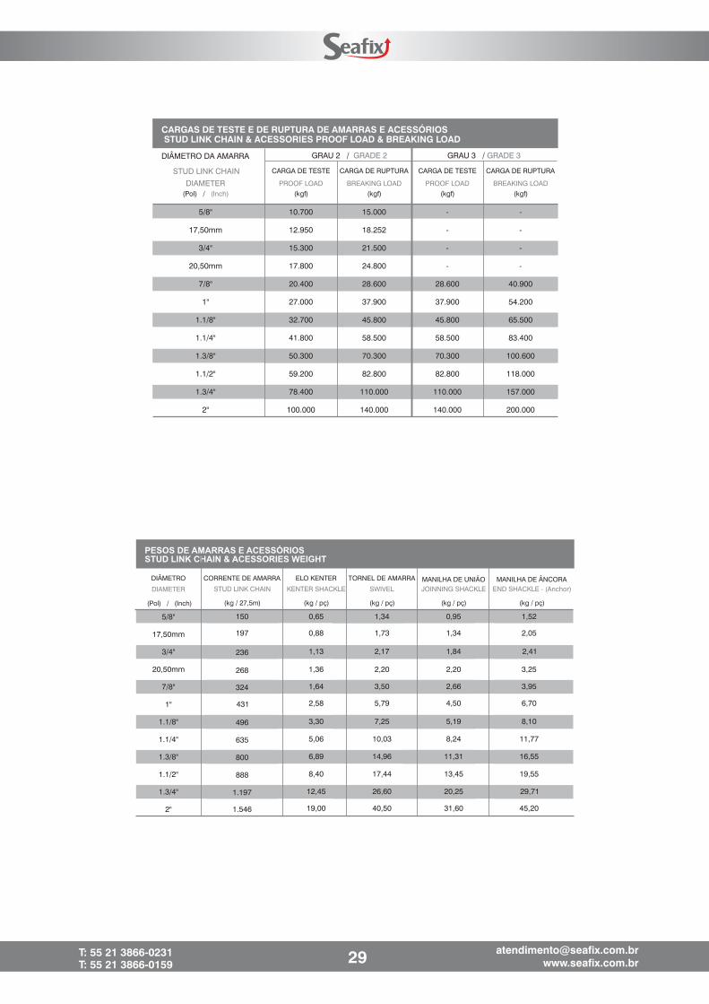
CARGA DE TESTE CARGA DE RUPTURA CARGA DE TESTE CARGA DE RUPTURA
PROOF LOAD BREAKING LOAD PROOF LOAD BREAKING LOAD(Pol) / (Inch) (kgf) (kgf) (kgf) (kgf)
5/8" 10.700 15.000 - -
17,50mm 12.950 18.252 - -
3/4" 15.300 21.500 - -
20,50mm 17.800 24.800 - -
7/8" 20.400 28.600 28.600 40.900
1" 27.000 37.900 37.900 54.200
1.1/8" 32.700 45.800 45.800 65.500
1.1/4" 41.800 58.500 58.500 83.400
1.3/8" 50.300 70.300 70.300 100.600
1.1/2" 59.200 82.800 82.800 118.000
1.3/4" 78.400 110.000 110.000 157.000
2" 100.000 140.000 140.000 200.000
GRAU 2 / GRADE 2 GRAU 3 / GRADE 3DIÂMETRO DA AMARRA
STUD LINK CHAIN
DIAMETER
CARGAS DE TESTE E DE RUPTURA DE AMARRAS E ACESSÓRIOSSTUD LINK CHAIN & ACESSORIES PROOF LOAD & BREAKING LOAD
CORRENTE DE AMARRA ELO KENTER TORNEL DE AMARRA MANILHA DE UNIÃO MANILHA DE ÂNCORASTUD LINK CHAIN KENTER SHACKLE SWIVEL JOINNING SHACKLE END SHACKLE - (Anchor)
(kg / 27,5m) (kg / pç) (kg / pç) (kg / pç)
DIÂMETRO
DIAMETER
(Pol) / (Inch)
5/8"
17,50mm
3/4"
20,50mm
7/8"
1"
1.1/8"
1.1/4"
1.3/8"
1.1/2"
1.3/4"
2"
PESOS DE AMARRAS E ACESSÓRIOSSTUD LINK CHAIN & ACESSORIES WEIGHT
150 0,65 1,34 0,95 1,52
197 0,88 1,73 1,34 2,05
236 1,13 2,17 1,84 2,41
268 1,36 2,20 2,20 3,25
324 1,64 3,50 2,66 3,95
431 2,58 5,79 4,50 6,70
496 3,30 7,25 5,19 8,10
635 5,06 10,03 8,24 11,77
800 6,89 14,96 11,31 16,55
888 8,40 17,44 13,45 19,55
1.197 12,45 26,60 20,25 29,71
1.546 19,00 40,50 31,60 45,20
(kg / pç)
29T: 55 21 3866-0231T: 55 21 3866-0159

7 d6 d
3.6 d4 d
6.6 d
3.96 d
ELO FINAL (EF) ELO INTERMEDIÁRIO (EI) ELO COMUM (EC)
CORRENTE DE AMARRA (CRA) / KENTER SHACKLE
EF
EI EI
ECTORNEL
QUARTEL DE TORNEL
30T: 55 21 3866-0231T: 55 21 3866-0159
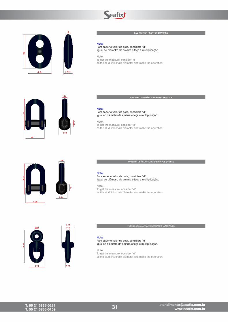
d
1.52d4.2d
6d
Nota:Para saber o valor da cota, considere “d”igual ao diâmetro da amarra e faça a multiplicação.
Note:To get the measure, consider “d”as the stud link chain diameter and make the operation.
ELO KENTER / KENTER SHACKLE
MANILHA DE UNIÃO / JOINNING SHACKLE
2.8d
1.3d
1.6d
7.1d
4d
Nota:Para saber o valor da cota, considere “d”igual ao diâmetro da amarra e faça a multiplicação.
Note:To get the measure, consider “d”as the stud link chain diameter and make the operation.
1.4d
9.7d
4.7d
3.4d
1.1d
1.2d
TORNEL DE AMARRA / STUD LINK CHAIN SWIVEL
Nota:Para saber o valor da cota, considere “d”igual ao diâmetro da amarra e faça a multiplicação.
Note:To get the measure, consider “d”as the stud link chain diameter and make the operation.
3.1d
1.4d
1.8d
8.7d
5.2d
Nota:Para saber o valor da cota, considere “d”igual ao diâmetro da amarra e faça a multiplicação.
Note:To get the measure, consider “d”as the stud link chain diameter and make the operation.
MANILHA DE ÂNCORA / END SHACKLE (Anchor)
31T: 55 21 3866-0231T: 55 21 3866-0159
h1
D
h2
h
a
a
h
a
h
WLL
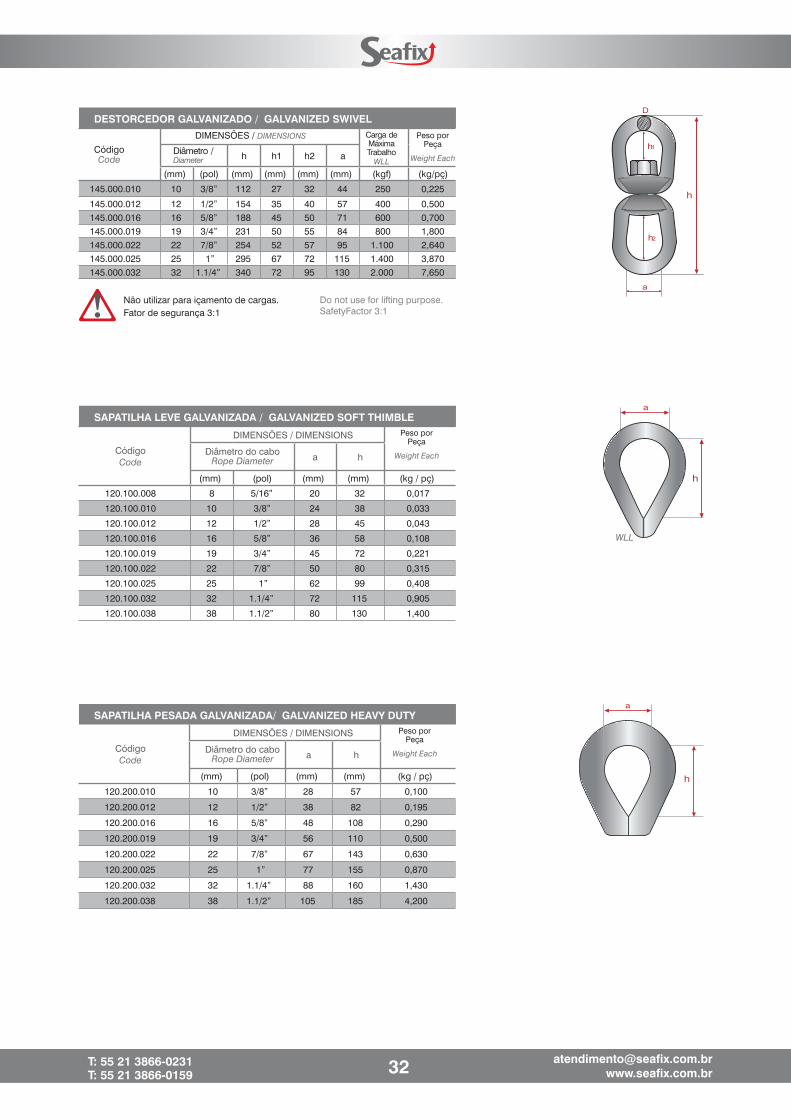
SAPATILHA PESADA GALVANIZADA/ GALVANIZED HEAVY DUTY
a h
(mm) (pol) (mm) (mm) (kg / pç)
120.200.010 10 3/8” 28 57 0,100
120.200.012 12 1/2” 38 82 0,195
120.200.016 16 5/8” 48 108 0,290
120.200.019 19 3/4” 56 110 0,500
120.200.022 22 7/8” 67 143 0,630
120.200.025 25 1” 77 155 0,870
120.200.032 32 1.1/4” 88 160 1,430
120.200.038 38 1.1/2” 105 185 4,200
CódigoCode
DIMENSÕES / DIMENSIONS
Diâmetro do caboRope Diameter
Peso porPeça
Weight Each
SAPATILHA LEVE GALVANIZADA / GALVANIZED SOFT THIMBLE
CódigoCode
DIMENSÕES / DIMENSIONS
Diâmetro do caboRope Diameter a h
(mm) (pol) (mm) (mm) (kg / pç)
120.100.008 8 5/16” 20 32 0,017
120.100.010 10 3/8” 24 38 0,033
120.100.012 12 1/2” 28 45 0,043
120.100.016 16 5/8” 36 58 0,108
120.100.019 19 3/4” 45 72 0,221
120.100.022 22 7/8” 50 80 0,315
120.100.025 25 1” 62 99 0,408
120.100.032 32 1.1/4” 72 115 0,905
120.100.038 38 1.1/2” 80 130 1,400
Peso porPeça
Weight Each
Não utilizar para içamento de cargas.Fator de segurança 3:1
Do not use for lifting purpose.SafetyFactor 3:1
DESTORCEDOR GALVANIZADO / GALVANIZED SWIVEL
h h1 h2 a
(mm) (pol) (mm) (mm) (mm) (mm) (kgf) (kg/pç)
145.000.010 10 3/8” 112 27 32 44 250 0,225
145.000.012 12 1/2” 154 35 40 57 400 0,500
145.000.016 16 5/8” 188 45 50 71 600 0,700
145.000.019 19 3/4” 231 50 55 84 800 1,800
145.000.022 22 7/8” 254 52 57 95 1.100 2,640
145.000.025 25 1” 295 67 72 115 1.400 3,870
145.000.032 32 1.1/4” 340 72 95 130 2.000 7,650
Diâmetro /Diameter
CódigoCode
DIMENSÕES / DIMENSIONS Carga deMáximaTrabalho
WLL
Peso porPeça
Weight Each
32T: 55 21 3866-0231T: 55 21 3866-0159
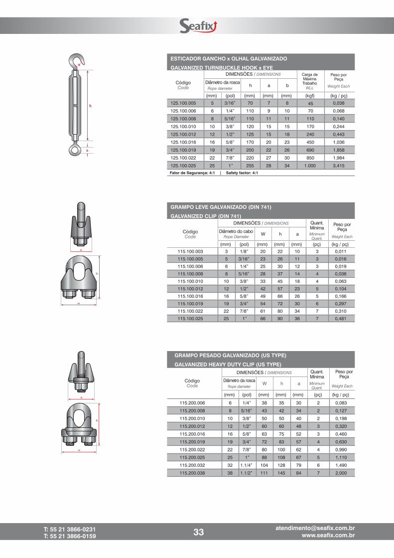
w
h
a
Diâmetro do caboCódigoCode
DIMENSÕES / DIMENSIONS Quant.Mínima
Peso porPeça
Weight Each
GRAMPO LEVE GALVANIZADO (DIN 741)
GALVANIZED CLIP (DIN 741)
W h a
(mm) (pol) (mm) (mm) (mm) (pç) (kg / pç)
115.100.003 3 1/8” 20 22 10 3
115.100.005 5 3/16” 23 26 11 3
115.100.006 6 1/4” 25 30 12 3
115.100.008 8 5/16” 28 37 14 4
115.100.010 10 3/8” 33 45 18 4
115.100.012 12 1/2” 42 57 23 5
115.100.016 16 5/8” 49 66 26 5
115.100.019 19 3/4” 54 72 30 6
115.100.022 22 7/8” 61 80 34 7
115.100.025 25 1” 66 90 36 7 0,481
MinimumQuant.Rope Diameter
ESTICADOR GANCHO x OLHAL GALVANIZADO
GALVANIZED TURNBUCKLE HOOK x EYE
h a b
(mm) (pol) (mm) (mm) (mm) (kgf) (kg / pç)
125.100.005 5 3/16” 70 7 8 45 0,038
125.100.006 6 1/4” 110 9 10 70 0,068
125.100.008 8 5/16” 110 11 11 110 0,140
125.100.010 10 3/8” 120 15 15 170 0,244
125.100.012 12 1/2” 125 15 18 240 0,443
125.100.016 16 5/8” 170 20 23 450 1,036
125.100.019 19 3/4” 200 22 26 690 1,858
125.100.022 22 7/8” 220 27 30 850 1,984
125.100.025 25 1” 255 28 34 1.000 3,415
Fator de Segurança: 4:1 | Safety factor: 4:1
Diâmetro da roscaCódigoCode
DIMENSÕES / DIMENSIONS
Rope diameter
Carga deMáximaTrabalho
WLL
Peso porPeça
Weight Each
w
h
a
GRAMPO PESADO GALVANIZADO (US TYPE)
GALVANIZED HEAVY DUTY CLIP (US TYPE)
W h a
(mm) (pol) (mm) (mm) (mm) (pç) (kg / pç)
115.200.006 6 1/4” 38 35 30 2 0,083
115.200.008 8 5/16” 43 42 34 2 0,127
115.200.010 10 3/8” 50 50 40 2 0,198
115.200.012 12 1/2” 60 60 48 3 0,320
115.200.016 16 5/8” 63 75 52 3 0,460
115.200.019 19 3/4” 72 83 57 4 0,630
115.200.022 22 7/8” 80 100 62 4 0,990
115.200.025 25 1” 88 108 67 5 1,110
115.200.032 32 1.1/4” 104 128 79 6 1,490
115.200.038 38 1.1/2” 111 145 84 7 2,000
Diâmetro da roscaCódigoCode
DIMENSÕES / DIMENSIONS Peso porPeça
Rope diameter Weight EachMinimumQuant.
Quant.Mínima
33T: 55 21 3866-0231T: 55 21 3866-0159
0,011
0,016
0,019
0,036
0,063
0,104
0,166
0,297
0,310
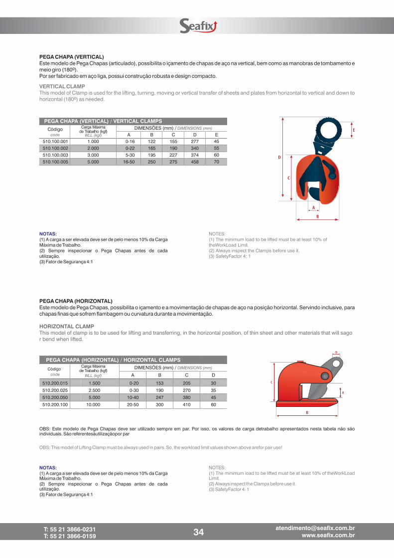
PEGA CHAPA (HORIZONTAL)Este modelo de Pega Chapas, possibilita o içamento e a movimentação de chapas de aço na posição horizontal. Servindo inclusive, parachapas finas que sofrem flambagem ou curvatura durante a movimentação.
HORIZONTAL CLAMPThis model of clamp is to be used for lifting and transferring, in the horizontal position, of thin sheet and other materials that will sagor bend when lifted.
NOTAS:(1) A carga a ser elevada deve ser de pelo menos 10% da CargaMáxima de Trabalho.(2) Sempre inspecionar o Pega Chapas antes de cadautilização.(3) Fator de Segurança 4:1
NOTES:(1) The minimum load to be lifted must be at least 10% of theWorkLoadLimit.(2) Always inspect the Clamps before use it.(3) SafetyFactor 4: 1
OBS: Este modelo de Pega Chapas deve ser utilizado sempre em par. Por isso, os valores de carga detrabalho apresentados nesta tabela não sãoindividuais. São referentesàutilizaçãopor par
OBS: This model of Lifting Clamp must be always used in pairs. So, the workload limit values shown above arefor pair use!
PEGA CHAPA (HORIZONTAL) / HORIZONTAL CLAMPS
A B C DCódigo DIMENSÕES (mm) / DIMENSIONS (mm)
code
Carga Máximade Trabalho (kgf)
WLL (kgf)
510.200.015
510.200.025
510.200.050
510.200.100
1.500
2.500
5.000
10.000
0-20
0-30
10-40
20-50
153
190
247
300
205
270
380
410
30
35
45
60
NOTAS:(1) A carga a ser elevada deve ser de pelo menos 10% da CargaMáxima de Trabalho.(2) Sempre inspecionar o Pega Chapas antes de cadautilização.(3) Fator de Segurança 4:1
NOTES:(1) The minimum load to be lifted must be at least 10% oftheWorkLoad Limit.(2) Always inspect the Clamps before use it.(3) SafetyFactor 4: 1
PEGA CHAPA (VERTICAL)Este modelo de Pega Chapas (articulado), possibilita o içamento de chapas de aço na vertical, bem como as manobras de tombamento emeio giro (180º).Por ser fabricado em aço liga, possui construção robusta e design compacto.
VERTICAL CLAMPThis model of Clamp is used for the lifting, turning, moving or vertical transfer of sheets and plates from horizontal to vertical and down tohorizontal (180º) as needed.
PEGA CHAPA (VERTICAL) / VERTICAL CLAMPS
Código DIMENSÕES (mm) / DIMENSIONS (mm)
A B C D Ecode
Carga Máximade Trabalho (kgf)
WLL (kgf)
510.100.001510.100.002510.100.003510.100.005
1.0002.0003.0005.000
0-160-225-30
16-50
122165195250
155190227275
277340374458
45556070
34T: 55 21 3866-0231T: 55 21 3866-0159