one-wire digital thermometer
TRANSCRIPT

Majalat Al-Ulum Al-Insaniya wat - Tatbiqiya
37
One-Wire Digital Thermometer
Omar O. Aldawibi and Abdalbaqi M. Alama1
Abstract
In this paper we have designed and implemented a One-Wire digital
thermometer. This thermometer was implemented using DS188B20 digital
sensor and PIC18F4520 microcontroller. The thermometer measures
temperatures from –55°C to +125°C. The program of the thermometer was
developed using microC PRO for PIC. Then the program was compiled
(assembled). After that, the circuit diagram of the thermometer was
simulated and tested successfully using Proteus program (ISIS part). The
hexa file of the program was downloaded to the PIC18F4520
microcontroller using PICkit3 programmer. Then the completed circuit
board for the digital thermometer was implemented. The temperature was
displayed on LCD and transmitted to a computer using the serial port
(USART).
I. Introduction
A microcontroller is a computer control system on a single chip. It has
many electronic circuits built into it, which can decode written instructions
and convert them to electrical signals. The microcontroller will then step
through these instructions and execute them one by one. As an example of
this a microcontroller could be instructed to measure the temperature of a
room and turn on a heater if it goes cold. The list of these instructions given
to the microcontroller is called a program [1].
The microcontroller on a single chip has features similar to those of our
standard personal computer. Primarily, the microcontroller is capable of
storing and running a program (its most important feature). The
microcontroller contains a CPU (central processing unit), RAM (random
access memory), ROM (read only memory), I/O (input/output) lines, serial
1 The Higher Polytechnic Institute in Zliten , Electronic and Electronic Engineering Dept.
Zliten – Libya.

One-Wire Digital Thermometre
38
and parallel ports, timers and sometimes other built in peripherals as A/D
(analog to digital) and D/A (digital to analog) converters [2].
Microchip Technology’s series of microcontrollers is called PIC
(peripheral interface controller). Microchip uses PIC to describe its series
of PIC microcontrollers. PIC microcontroller is a very popular 8-bit chip,
used in a wide variety of applications.
LCDs (Liquid Crystal Display) are alphanumeric displays which are
frequently used in microcontroller-based applications. Some of the
advantages of LCDs are their low cost and low power consumption. LCDs
are ideal in low-power, battery-operated portable applications. These
displays come in different shapes and sizes [3] [4].
The mikroC PRO for PIC (from MikroElektronika) is a powerful
program for PIC microcontrollers. It is designed to provide the programmer
with the easiest possible solution to developing applications for embedded
systems. Fortunately, this program provides a set of libraries which
simplify the initialization and use of PIC microcontrollers. The One-Wire
library provides routines for communication via the Dallas One-Wire
protocol, e.g. with DS18B20 digital thermometer. The LCD library
provides special commands for displaying data on LCDs. All the user has to
do is connect the LCD to the appropriate I/O ports and then use these
special commands to simply send data to the LCD [7].
Proteus (from Labcenter Electronics) consists of two main parts, ISIS
and ARES. ARES is a layout package, which is used to create a PCB when
the circuit has been designed. ISIS is the schematic capture and interactive
simulation software used to create the circuit drawing and to test the circuit
prior to building the real hardware [6].
DS18B20 is One-Wire interface digital thermometer that require one
port pin (and ground) for communication, has a unique 64-bit serial code
stored in an onboard ROM, can measure temperatures from -55°C to
+125°C (-67F to +257F), and user-selectable resolution from 9 to 12 bits
[8].
The aim of this work is to build a One-Wire digital thermometer using
DS18B20 digital sensor. The temperature will displayed using a 2×16_LCD
module. The mikroC PRO is used to work with PIC18F4520. It is a great
device to play with because of its flash memory. “Flash” memory means it
can be programmed over and over again without having to erase it under
ultraviolet light. The designed circuit is simulated and tested using ISIS

Majalat Al-Ulum Al-Insaniya wat - Tatbiqiya
39
software. Then PICkit3 programmer from microchip is used to download
the program to the PIC.
II. The One-Wire Protocol
Maxim Integrated Products’ Dallas Semiconductor division developed
the “One-Wire” protocol as an economical way of exchanging information
between microprocessors and ancillary chips. It’s called a One-Wire
network because it uses one wire (plus ground) to communicate with the
master microcontroller. One-wire devices are slaves and communicate only
when commanded by the master [3] [5].
Slave devices on the One-Wire bus can get their power supply from
external supply or from data line. Some basic characteristics of this
protocol are:
• single master system,
• low cost,
• low transfer rates (up to 16 kb/s),
• fairly long distances (up to 300 meters),
• small data transfer packages.
Each One-Wire device has a unique 64-bit registration, so multiple slaves
can co-exist on the same bus [7].
Dallas digital thermometers like (DS18B20) communicate with the
master device using One-Wire protocol. Oscillator frequency needs to be at
least 4MHz in order to use the routines with these thermometers [7].
III. DS18B20 Digital Temperature Sensor
The DS18B20 Digital Thermometer provides 9 to 12–bit centigrade
temperature measurements and has an alarm function with nonvolatile user-
programmable upper and lower trigger points. The DS18B20 communicates
over a One-Wire bus that by definition requires only one data line (and
ground) for communication with a central microprocessor. It has an
operating temperature range of –55°C to +125°C and is accurate to ±0.5° C
over the range of –10°C to +85°C. In addition, the DS18B20 can derive
power directly from the data line (“parasite power”), eliminating the need
for an external power supply.

One-Wire Digital Thermometre
40
Each DS18B20 has a unique 64-bit serial code, which allows multiple
DS18B20s to function on the same One–Wire bus; thus, it is simple to use
one microprocessor to control many DS18B20s distributed over a large area
[8].
IV. Block Diagram of the DS18B20 Sensor
Figure (1) shows a block diagram of the DS18B20, and pin descriptions
are given in figure (2). The 64-bit ROM stores the device’s unique serial
code. The scratchpad memory contains the 2-byte temperature register that
stores the digital output from the temperature sensor. In addition, the
scratchpad provides access to the 1-byte upper and lower alarm trigger
registers (TH and TL), and the 1-byte configuration register. The
configuration register allows the user to set the resolution of the
temperature-to-digital conversion to 9, 10, 11, or 12 bits. The TH, TL and
configuration registers are nonvolatile (EEPROM), so they will retain data
when the device is powered down [8].
The DS18B20 uses Dallas’ exclusive One-Wire bus protocol that
implements bus communication using one control signal. The control line
requires a weak pull-up resistor since all devices are linked to the bus via a
3-state or open-drain port (the DQ pin in the case of the DS18B20). In this
bus system, the microprocessor (the master device) identifies and addresses
devices on the bus using each device’s unique 64-bit code. Because each
device has a unique code, the number of devices that can be addressed on
one bus is virtually unlimited [8].
Fig. (1) Block Diagram of the DS18B20

Majalat Al-Ulum Al-Insaniya wat - Tatbiqiya
41
GND ground
DQ data Input/output pin
VDD optional VDD pin
NC not connected
Fig. (2) Pin description of the DS18B20
V. Powering the DS18B20 Sensor
The DS18B20 may be powered by an external supply on VDD as shown
in figure (3). Another feature of the DS18B20 is the ability to operate
without an external power supply. Power is instead supplied through the
One-Wire pull-up resistor via the DQ pin when the bus is high. The high
bus signal also charges an internal capacitor (CPP), which then supplies
power to the device when the bus is low. This method of deriving power
from the One-Wire bus is referred to as “parasite power”.
Parasite power is very useful for applications that require remote
temperature sensing or those are very space constrained. For more
information return to DS18B20 Datasheet [8].
Fig. (3) Powering the DS18B20 with an external supply

One-Wire Digital Thermometre
42
VI. Operation of Temperature Measurement
The DS18B20 output temperature data is calibrated in degrees
centigrade. The temperature data is stored in the temperature register (see
Figure (4)). For temperature below 0°C the temperature data is stored as a
16-bit sign-extended two’s complement number. The sign bits (S) indicate
if the temperature is positive or negative: for positive numbers S=0 and for
negative numbers S=1. If the DS18B20 is configured for 12-bit resolution,
all bits in the temperature register will contain valid data. For 11-bit
resolution, bit 0 is undefined. For 10-bit resolution, bits 1 and 0 are
undefined, and for 9-bit resolution bits 2, 1 and 0 are undefined. Table (1)
gives examples of digital output data and the corresponding temperature
reading for 12-bit resolution conversions.
Fig. (4) Temperature register format
The resolution of the temperature sensor is user-configurable to 9, 10,
11, or 12 bits, corresponding to increments of 0.5°C, 0.25°C, 0.125°C, and
0.0625°C, respectively. The default resolution at power-up is 12-bit [8].
Table (1) Example of temperature readings

Majalat Al-Ulum Al-Insaniya wat - Tatbiqiya
43
The DS18B20’s memory is organized as shown in Figure (5). The
memory consists of an SRAM scratchpad with nonvolatile EEPROM
storage for the high and low alarm trigger registers (TH and TL) and
configuration register.
The first two bytes (byte 0 and byte 1) are read-only memory that
contain the LSB and the MSB of the temperature register. Bytes 2 and 3
provide access to TH and TL registers. Byte 4 is a configuration register.
Bytes 5,6 and 7 are reserved. Byte 8 is read-only and contains CRC code
(cyclic redundancy check) for byte 0 through byte 7 of the scratchpad.
Fig. (5) DS18B20 Memory
To access the DS18B20's data, three steps sequence as follows is need.
• Initialization. All transactions on the One-Wire bus begin with an
initialization sequence. It consists of a reset pulse transmitted by the
bus master followed by presence pulse transmitted by the slave.
• Issue a ROM command after the bus master has detected a presence
pulse. ROM commands are : Search ROM[F0h], Read ROM[33h],
Match ROM[55h], Skip ROM[CCh] and Alarm Search[ECh].
• Issue a DS18B20 function command after a ROM command. A ROM
command is to select which DS18B20 that the master wants to
communicate with. A function command allows the master to read
and to write from the DS18B20's scratchpad, etc. DS18B20 function
commands are: Convert T[44h], Write Scratchpad[4Eh], Read

One-Wire Digital Thermometre
44
Scratchpad[BEh], Copy Scratchpad[48h], Recall E2[B8h], and Read
Power Supply[B4h].
It is very important to follow this sequence every time the DS18B20 is
accessed. Exceptions to this rule are Search ROM[F0] and Alarm
Search[EC] commands. The master must return to step 1 after issue either
of those ROM commands. (Return to Datasheet for more information) [8].
VII. Interfacing the DS18B20 Temperature Sensor (Circuit Diagram)
Our purpose is to build One-Wire digital thermometer. The digital
thermometer software, which appended in the end of this paper, is
developed using mikroC PRO for PIC. This software is simulated and
tested successfully using ISIS software. Then PICkit3 programmer is used
to download the program to the PIC. The thermometer measures
temperatures from –55°C to +125°C. The PIC18F4520 is used as a master
device and the DS18B20 is used as slave devise. The frequency of the
crystal oscillator is equal to 4MHz. The data line of DS18B20 is connected
to PIC through the first pin of port B (RB0). The resolution of the
temperature sensor is chosen to be 12 bit. The temperature is displayed
using a 2×16_LCD. The display format of the temperature is 'xxx.xxxx°C'.
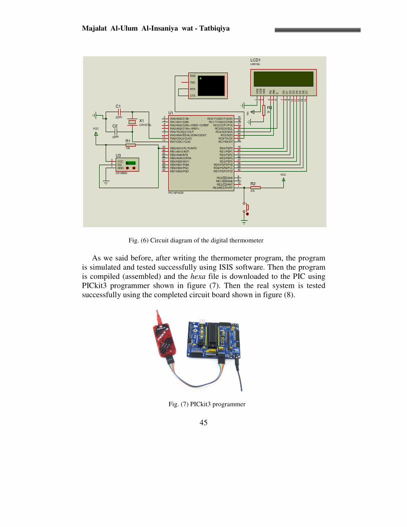
Figure (6) shows the circuit diagram of the thermometer. This figure
shows how to connect the LCD to the PIC. The PIC reads the temperature
from the sensor and prints it on the LCD and transmits it through the serial
port (USART) to a computer. The computer receives the transmitted
temperature and displays it using any software (developed with Delphi
language for example).
Majalat Al-Ulum Al-Insaniya wat - Tatbiqiya
45
Fig. (6) Circuit diagram of the digital thermometer
As we said before, after writing the thermometer program, the program
is simulated and tested successfully using ISIS software. Then the program
is compiled (assembled) and the hexa file is downloaded to the PIC using
PICkit3 programmer shown in figure (7). Then the real system is tested
successfully using the completed circuit board shown in figure (8).
Fig. (7) PICkit3 programmer
D7
14
D6
13
D5
12
D4
11
D3
10
D2
9D
18
D0
7
E6
RW
5R
S4
VS
S1
VD
D2
VE
E3
LCD1LM016L
VCC
R2
47k
R1
10k
VCC
RA0/AN0/C1IN-2
RA1/AN1/C2IN-3
RA2/AN2/C2IN+/VREF-/CVREF4
RA3/AN3/C1IN+/VREF+5
RA4/T0CKI/C1OUT6
RA5/AN4/SS/HLVDIN/C2OUT7
RA6/OSC2/CLKO14
RA7/OSC1/CLKI13
RB0/AN12/FLT0/INT033
RB1/AN10/INT134
RB2/AN8/INT235
RB3/AN9/CCP2A36
RB4/KBI0/AN1137
RB5/KBI1/PGM38
RB6/KBI2/PGC39
RB7/KBI3/PGD40
RC0/T1OSO/T13CKI15
RC1/T1OSI/CCP2B16
RC2/CCP1/P1A17
RC3/SCK/SCL18
RC4/SDI/SDA23
RC5/SDO24
RC6/TX/CK25
RC7/RX/DT26
RD0/PSP019
RD1/PSP120
RD2/PSP221
RD3/PSP322
RD4/PSP427
RD5/PSP5/P1B28
RD6/PSP6/P1C29
RD7/PSP7/P1D30
RE0/RD/AN58
RE1/WR/AN69
RE2/CS/AN710
RE3/MCLR/VPP1
U1
PIC18F4520
R32k
-52.0DQ
2VCC
3
GND1
U3
DS18B20
vcc
X1CRYSTAL
C1
22PF
C2
22PF
RXD
RTS
TXD
CTS

One-Wire Digital Thermometre
46
Fig. (8) Completed circuit board for the digital thermometer
Conclusions
As mentioned before, our goal is to build One-Wire digital thermometer.
The program was written using mikroC pro for PIC and tested successfully
using ISIS software. After that, the completed circuit board of the
thermometer was connected and the thermometer program was downloaded
to the PIC. The temperature was displayed on the LCD and transmitted to
the computer through serial port successfully.

Majalat Al-Ulum Al-Insaniya wat - Tatbiqiya
47
A primary advantage of the One-Wire bus is that we may place many
sensors on it, and selectively read each one.
Microcontrollers are changing electronic designs. Instead of hard wiring
a number of logic gates together to perform some function we can use
instructions to wire the gates electronically. Therefore we conclude that the
software for any system can be considered as an extremely part of the
whole system to increase its capabilities and modes of operations.
References
[1] D. W. Smith. "PIC in Practice: A project-Based Approach", ISBN-13:
978-0 75-066826-2, Newnes, Elsevier, second edition 2006.
[2] Tim Wilmshurst, "Designing Embedded Systems with PIC
Microcontrollers: Principles and applications", ISBN-13: 978-0-7506-
6755-5, Newnes, Elsevier, first edition 2007.
[3] Lucio Di Jasio, Tim Wilmshurst, Dogan Ibrahim, John Morton, Martin
Bates, Jack Smith, D.W. Smith, and Chuck Hellebuyck, "PIC
Microcontrollers: Know It All", ISBN-13: 978-0-7506-8615-0, Newnes,
Elsevier, 2008.
[4] Dogan Ibrahim, " PIC BASIC Projects: 30 Projects Using PIC BASIC
and PIC BASIC PRO", ISBN-10: 0-75-066879-2, Newnes, Elsevier,
2006.
[5] Jack R. Smith, "Programming the PIC Microcontroller with MBasic"
ISBN: 0-7506-7946-8, Newnes, Elsevier, 2005.
[6] Labcenter Electronics, "Proteus software", www.labcenter.co.uk
[7] MikroElektronika, "MikroC PRO for PIC", www.mikroe.com
[8] DS18B20 Datasheet, www.maxim-ic.com
APPENDIX The developed software for the digital thermometer
sbit LCD_RS at Rc4_bit;
sbit LCD_EN at Rc3_bit;
sbit LCD_D7 at Rd7_bit;
sbit LCD_D6 at Rd6_bit;
sbit LCD_D5 at Rd5_bit;
sbit LCD_D4 at Rd4_bit;
sbit LCD_D3 at Rd3_bit;
sbit LCD_D2 at Rd2_bit;

One-Wire Digital Thermometre
48
sbit LCD_D1 at Rd1_bit;
sbit LCD_D0 at Rd0_bit;
sbitLCD_rw at Rc5_bit;
sbitLCD_RS_Direction at TRISc4_bit;
sbitLCD_EN_Direction at TRISc3_bit;
sbit LCD_D7_Direction at TRISd7_bit;
sbit LCD_D6_Direction at TRISd6_bit;
sbit LCD_D5_Direction at TRISd5_bit;
sbit LCD_D4_Direction at TRISd4_bit;
sbit LCD_D3_Direction at TRISd3_bit;
sbit LCD_D2_Direction at TRISd2_bit;
sbit LCD_D1_Direction at TRISd1_bit;
sbit LCD_D0_Direction at TRISd0_bit;
sbitLCD_rw_Direction at TRISc5_bit;
voidDsply_Tmp(unsigned int //function prototype
char *txt = "000.0000";
unsignedtmp;
void main()
{ ADCON1 |= 0x0F; // Configure all ports with analog function as
digital I/O
CMCON |= 7; // Disable comparators
trisa=0; trisb=1; trisc=0b11000000; trisd=0; portb=0; portc=0;
portd=0;
rcsta |= 0x80;
UART1_Init(9600); // Initialize UART module at 9600 bps
Delay_ms(100); // Wait for UART module to stabilize
Lcd_Init();
Lcd_Cmd(_LCD_CURSOR_OFF);
Lcd_Out(1, 1, " Temperature: ");
// Print degree character, 'C' for Centigrades
Lcd_Chr(2,13,223);
Lcd_Chr(2,14,'C');
// main loop
while(1)
{ Ow_Reset(&PORTb,0); // Onewire reset signal
Ow_Write(&PORTb,0,0xCC); // Issue command SKIP_ROM
Ow_Write(&PORTb,0,0x44); // Issue command CONVERT_T
Delay_us(120);

Majalat Al-Ulum Al-Insaniya wat - Tatbiqiya
49
Ow_Reset(&PORTb,0);
Ow_Write(&PORTb,0,0xCC); // Issue command SKIP_ROM
Ow_Write(&PORTb,0,0xBE); // Issue command
READ_SCRATCHPAD
tmp = Ow_Read(&PORTb,0);
tmp = (Ow_Read(&PORTb,0) << 8) + tmp;
Dsply_Tmp(tmp);
UART1_Write_text(txt); //transmit tmp to PC
Delay_ms(500);
}
}
voidDsply_Tmp(unsigned inttmp_wrt)
{charall_tmp;
unsignedinttmp_frct;
if (tmp_wrt& 0x8000)
{
txt[0] = '-'; //temperature is negative
tmp_wrt = ~ tmp_wrt + 1; //2's complement
}
else
{
txt[0]='0'; //temperature is positive
}
all_tmp = tmp_wrt>>4 ;
if (all_tmp/100)
txt[0] = all_tmp/100 + 48;
txt[1] = (all_tmp/10)%10 + 48; // extract tens digit
txt[2] = all_tmp%10 + 48; // extract ones digit
tmp_frct =tmp_wrt&= 0x000F;
tmp_frct *= 625;
txt[4] = tmp_frct/1000 + 48; // extract thousands digit
txt[5] = (tmp_frct/100)%10 + 48; // extract hundreds digit
txt[6] = (tmp_frct/10)%10 + 48; // extract tens digit
txt[7] = tmp_frct%10 + 48; // extract ones digit
Lcd_Out(2, 5, txt);
}