one piece windo€¦ · this one piece window conversion. it was designed to be installed by a...
TRANSCRIPT

One Piece Products Patent Pending
(888)One-Products
8 8 8 6 6 3 - 7 7 6 3
www.OnePieceProducts.com

2
Installation Manual
____________________________________________
One Piece Products
Conversion kit
Series 1
1973-1991 GM Truck bodies

3
First and foremost I would personally like to thank for you interest in
this one piece window conversion. It was designed to be installed by a
novice. In this kit you will find all the necessary hardware needed to perform
the conversion. Please keep in mind that the new felt assemblies will need a
break in period and might need a little adjustment in the near future after the
initial break in.
In the following pages you will find detailed pictures on the
installation process. These pictures will have a short one to two line
description of what is being done in the step mentioned.
If there are any difficulties that you can’t figure out, Please feel free to
reach technical support at (888)663-7763 During the business hours of 9:00
a.m. to 4:00 p.m. Monday thru Friday – Pacific Standard Time.

4
KIT CONTENTS
1. 4” extension. (Used to push back the
original rear guide rail closer to the door latch.). Quantity
(2)
2. Run Channel. (Used to replace the
old run channel with a new longer one.) Quantity
(2)
3. Roller Channel (Used to replace the
old roller channel, has two holes one on each end including fold
down tabs.) Mounts between door glass brackets and the rollers on
the regulator .
Quantity (2)

5
4. Front Main Guide (Used to guide the
front part of the door glass in a vertical motion parallel with the
back guide.) Marked Left or Right
Quantity (2)
5. Rubber Spacer ½”x ¼” (Used to take
the voided space left by the original vent glass assembly. Cut to
size. (8 pcs 7” long and 6pcs. 4” long.
Quantity (80”long)
6. Trim Adhesive (Used to glue on felt
and scraper assembly including the Rubber Spacer.)
Quantity (1)

6
7. Plastic Plugs (Used to cap off original
holes left by the old vent glass assembly). Requires a little dab of
trim adhesive before installation.
Quantity (6)
8. Outside Scrapers (Used to replace the
old scrapers with original looking new ones. Glue On – make sure
to put the glue on the body so as not to make too much of a mess.
Quantity (2)
9. Hardware (Nuts, bolts, washers, plugs,
expansion nuts,) Quantity
(assorted)
7
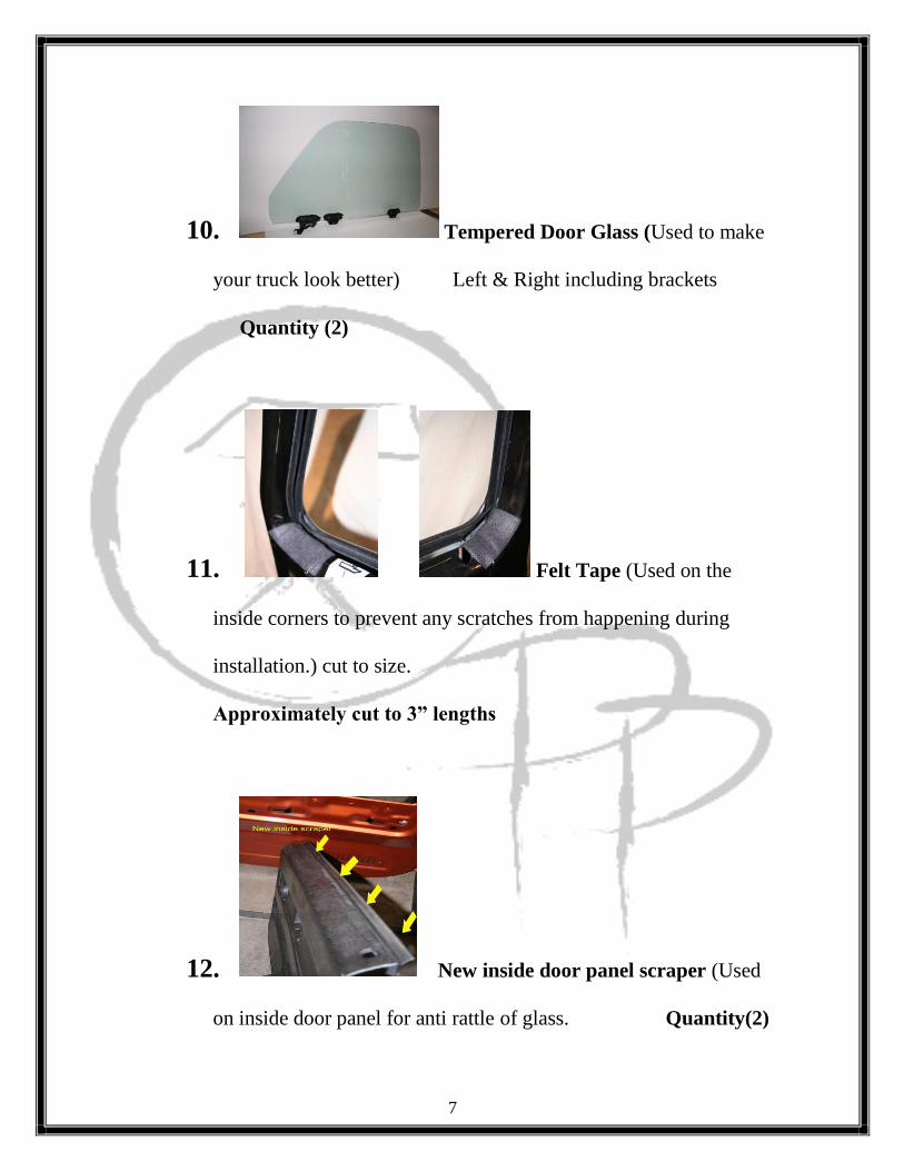
10. Tempered Door Glass (Used to make
your truck look better) Left & Right including brackets
Quantity (2)
11. Felt Tape (Used on the
inside corners to prevent any scratches from happening during
installation.) cut to size.
Approximately cut to 3” lengths
12. New inside door panel scraper (Used
on inside door panel for anti rattle of glass. Quantity(2)

8
Tools required
Small hammer.
1 ½” hole saw with Drill.
Drill or hand screwdriver with Phillips head tip.
Flat thin screwdriver.
1/4” nut driver or ratchet with 1/4”, 10mm, 7/16” socket
and 1/2" crescent wrench.
1/4” drill bit.
7/16” wrench.
Hand rivet gun w/ various tips.
Metal saw to cut sheet metal (hack-saw).
Small angle grinder(electric or air)
(PATIENCE)
6-Pack – lawn chair optional for breaks. .

9
Installation steps
(Please remember to follow the steps carefully.)
Brief disassembling steps:
1. Begin by taking all the screws from the door panel. Take the C-clip
from the door handle off, if in case it is a manual regulator assembly.
2. Some older models only have 2 vent assembly screws exposed on the
external part of the vent assembly (Most will have 3 screws.) Unscrew
all of them and take them off.
3. With the door panel off you will see two 7/16” Bolts lined up at the
bottom of the vent assembly. Take them off. (See above picture.)
4. Next to the spring located at the bottom of the vent glass frame pivot
point is a 1/4” bolt, you must also remove this bolt in order to pull the
whole vent window assembly out.

10
a. Tip to remember: in order to pull the vent window assembly
out, the door glass must be in the bottom position. Proceed to
remove vent glass assembly.
5. After removing the vent glass assembly, proceed to remove the door
glass by rolling up the door glass to the very top position where the
metal roller channel is in direct view, Slide the Door glass forward
until it is completely out.
a. Tip to remember: Make sure to be careful on sliding the door
glass forward so as not to hit the frame of the actual door.

11
6. After the Door Glass and Vent Glass Assembly have been removed,
continue to remove all the old felts and scrapers that are left on the
door. (the old brittle fuzzy stuff)
Assembling steps:

12
7. Continue on by removing the rear vertical guide that is right next to
the latch assembly of the door.
a. After you remove the rear vertical guide find the 4” extension
that is included in your kit and bolt one end of it as seen in the
picture below. The hole on the opposite side is for the original
hole on the door skin which will push the guide closer to the

13
door latch assembly
b. Don’t Forget to Slot the Hole for future adjustment

14
Roller install Important tip: Remember to remove the regulator
assembly if you need to change the new rollers that come with this kit. (Just
remember to grease the roller run channel and the front slide guide bracket.)

15
Below are pictures howing the new roller installation:
8. Door Lock Tumbler cutting In the next step you will have to
cut the tip from the elbow that engages to the door latch assembly,
simply refer to the pictures below. If this piece is not cut, it will be in
the way of the window during vertical motion.(VeryImportant) Step.

16
In this step your lock assembly should look like the picture
above.

17
9. Using Hole template In this step you’ll be using a template
to drill 3 holes in the door. One ½” hole, one 3/8” hole, and finally one 1
1/4” hole. The template is usable for both left and right sides. Simply line
up to the original 4 bolt holes of the manual regulator assembly to
those on the template. The holes are also measured and indicated in the
pictures below.
10. Cut & Fold In this step we will be cutting and folding the
reinforcement support that crosses the lower horizontal opening with the
hack-saw. (See picture below.)

18
Quick Note: Some doors will weaken due to this cutting. There is a step
to help in the event of this. Take a 1” x 1/4” straight bar and either JB
Weld it to the inside lip of where the New scraper mounts or Weld it in
place, Only if your are able too weld ofcourse. If you show a gap after
the installation of glass between the center of the glass and the scaper.
Simply Finessely rub the outside of the scraper area with the window in
the down position till the gap is closed. The sheet metal is flexible. Don’t
press too hard on the outside , this can cause a kink in your
sheetmetal.

19
11. Grinding Inside Hinge compression nut. On some doors you
will have to grind FLAT the inside hinge nut that is pressed on the door
itself. We supply the NEW shorter Bolt, but the glass may hit this nut
when about Half way down.
See pic for example.

20
This is an inside shot of the door facing the hinge
12. New C-Channel installtion The C-roller channel which is
fairly easy, simply slide the C-channel onto the new rollers

21
13. Plastic plug installation In this step we will install the plastic
plugs provided in the kit assembly. These plugs cover the original holes that
would were left by removed vent glass assembly. Quick tip: (add a little
dab of weather-strip adhesive to the plug so it will not pop out while
driving.) There are two different sizes of plugs that fit each hole
appropriately, PLEASE PAY ATTENTION to the picture below.

22
14. In step we will be installing the felt assemblies, including the
inner and outer scrapers and the required back spacer. Quick Tip: Add
adhesive to the felts and scrapers during installation. See picture below
Quick tip: You might need to widen the opening for the run channel. It
should roughly be 1” wide around the perimeter where the New run channel
goes.
Vent Spacer installation

23
In this picture on top, the yellow arrows indicate the position of
the
Spacers, while the green arrow indicate the inside view of the plastic
plugs
Installed on the previous step. The bottom corner nearest the
horizontal
curve should consist of 4 layers cut 4” long while the middle and
upper
Section should only be 2 layers cut 7” long of the 1/2” x 1/4”
spacer.
15. Following the spacer install, we continue with the run Channel
install indicated in the pictures below. Quick Tip: Notice the notches on the
sides of the run channel, they are the indicators of where to start the install.
The notch further from the end of the run channel goes on the back corners
of the door.

24
Make sure the front of new Run Channel looks like the bottom picture.
Some trucks will only
require 3 layered spacers while others will require the full four. I like to also
25
use expanding insulation foam that is used on houses. You can pick this up
at any Home Depot.
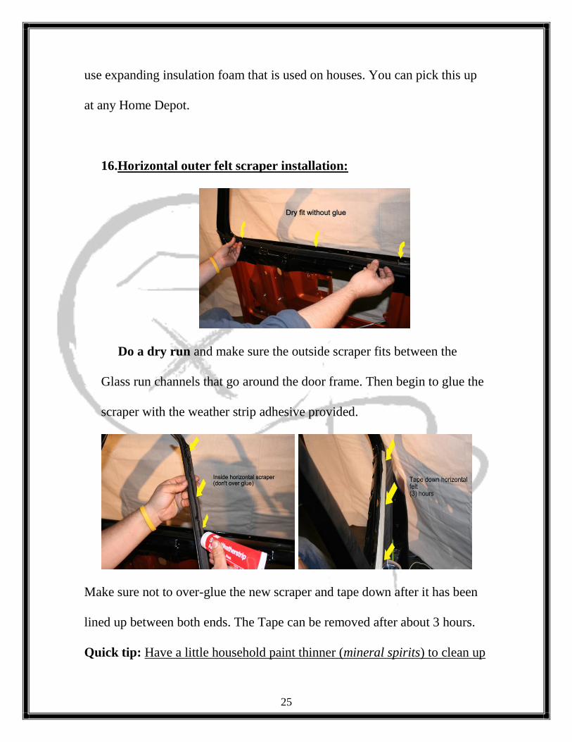
16.Horizontal outer felt scraper installation:
Do a dry run and make sure the outside scraper fits between the
Glass run channels that go around the door frame. Then begin to glue the
scraper with the weather strip adhesive provided.
Make sure not to over-glue the new scraper and tape down after it has been
lined up between both ends. The Tape can be removed after about 3 hours.
Quick tip: Have a little household paint thinner (mineral spirits) to clean up
26
any mess, This will not harm your paint in any way, just make sure to use it
right away before the glue dries.
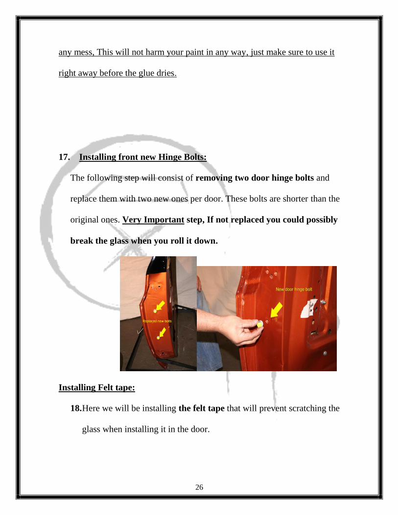
17. Installing front new Hinge Bolts:
The following step will consist of removing two door hinge bolts and
replace them with two new ones per door. These bolts are shorter than the
original ones. Very Important step, If not replaced you could possibly
break the glass when you roll it down.
Installing Felt tape:
18. Here we will be installing the felt tape that will prevent scratching the
glass when installing it in the door.

27
Installing tempered door glass;
19. Here we will be installing the new curved tempered door glass.
Just simply following the standard pictures. Drill a 1 ½” Access Hole
as shown below. Exactly 3”s from the orginal crank hole in the
direction of the lock.

28
You can also install the glass from the outside as well!
29
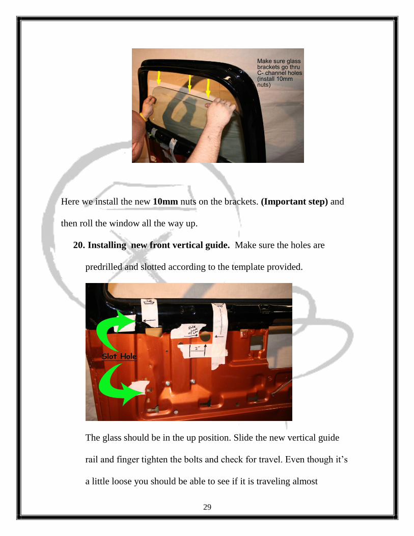
Here we install the new 10mm nuts on the brackets. (Important step) and
then roll the window all the way up.
20. Installing new front vertical guide. Make sure the holes are
predrilled and slotted according to the template provided.
The glass should be in the up position. Slide the new vertical guide
rail and finger tighten the bolts and check for travel. Even though it’s
a little loose you should be able to see if it is traveling almost

30
correctly. Roll it down then up and then tighten the nuts and lube all
the moving parts.
Installing inner door panel scraper:
23. Take a 1/8” drill bit with a drill and place the new inside door
glass scraper and center it on the door panel and drill to the
proper height (like in the picture below.)

31
21. Adjustments
If for any reason the window does not go up and down properly there
are adjustments that can be made by elongating the two of the vertical
guide holes as seen in the pictures below. (Only if needed)
Quick Tip: (Please remember that the new felt assemblies need to be
broken in for a couple of weeks.(2-3 weeks.) The window might not go
completely up just shy of reaching the top, again due to the brand new
Run Channels.

32

33
Power Lock actuator relocation
Just redrill the holes 8” down as shown below and go to your local
hardware store and pick up some 1/8” round or square bar and bend it in
a Z shape so it can fit the lock actuator and tie it together with a U-BOLT
and nuts that are used to tie together cables and your done.
Widening the Run Channel Cavity

34
Use Wooden end of a hammer to twist open the cavity of the
New Run Channel. Open to roughly about 1” wide measured
from the inside.

35
CONGRATULATIONS!!

36
Thank you
For purchasing
Our one piece kit.

37