one nation. one grid - nerldcnerldc.org/docs/dec14/ner reactive power management... · one nation....
TRANSCRIPT


One Nation. One Grid
REACTIVE POWER MANAGEMENT &
VOLTAGE CONTROL IN
NORTH EASTERN REGION
December 2014
POWER SYSTEM OPERATION CORPORATION LIMITED (A wholly owned subsidiary of Powergrid)
(A GOVT. OF INDIA UNDERTAKING)
NORTH EASTERN REGIONAL LOAD DESPATCH CENTRE SHILLONG
Edition �
Prepared by: System Operation - I department

REACTIVE POWER MANAGEMENT AND VOLTAGE CONTROL IN NORTH EASTERN REGION
Page 1 of 103
CONTENTS
EXECUTIVE SUMMARY 5
1 Reactive Power Management and Voltage Control 6 1.1 Introduction 6
1.2 Analogy of Reactive Power 8 1.3 Understanding Vectorially 10 1.4 Voltage Stability 11 1.5 Voltage Collapse 12 1.6 Proximity to Instability 13 1.7 Reactive reserve margin 14 1.8 NER GRID – OVERVIEW 17 1.9 Reliability improvement due to local voltage regulation 20
2 Transmission Lines and Reactive Power Compensation 21
2.1 Introduction 21 2.2 Surge impedance loading (SIL) 23 2.3 Shunt compensation in line 23 2.4 Line loading as function of line length and compensation 24
3 Series and Shunt Capacitor Voltage Control 40
3.1 Introduction 40 3.2 MeSEB capacity building and training document suggestion 41 3.3 THE ASSAM GAZETTE, EXTRAORDINARY, FEBRUARY 10, 2005 41
4 Transformer Load Tap Changer and Voltage Control 44
4.1 Introduction 44 4.2 THE ASSAM GAZETTE, EXTRAORDINARY, FEBRUARY 10, 2005 45
5 HVDC and Voltage Control 57
5.1 Introduction 57 5.2 HVDC Configuration 57 5.3 Reactive power source 60 5.4 ”Inter-regional Transmission system for power export from NER to NR/WR” 60
6 FACTS and Voltage Control 61
6.1 Introduction 61 6.2 Static Var Compensator (SVC) 61 6.3 Converter-based Compensator 62 6.4 Series-connected controllers 63

REACTIVE POWER MANAGEMENT AND VOLTAGE CONTROL IN NORTH EASTERN REGION
Page 2 of 103
7 Generator Reactive Power and Voltage Control 64 7.1 Introduction 64 7.2 Synchronous condensers 66
8 CONCLUSION 91
9 SUMMARY 89
10 Statutory Provisions for Reactive Power Management and Voltage Control 94
10.1 Provision in the Central Electricity Authority (Technical 94 Standard for connectivity to the grid) Regulations 2007 [8]:
10.2 Provision in the Indian Electricity Grid Code (IEGC), 2010 94 10.3 THE ASSAM GAZETTE, EXTRAORDINARY, FEBRUARY 10, 2005 99
11. Bibliography 103
Details of List
LIST-1: 400 KV LINE DETAILS OF POWERGRID IN NORTH EASTERN REGION 26 LIST-2: 400 KV LINE (CHARGED AT 220 KV) DETAILS OF POWERGRID IN NORTH
EASTERN REGION 26
LIST-3: 220 KV LINE DETAILS OF POWERGRID IN NORTH EASTERN REGION 27
LIST-4: 132 KV LINE DETAILS OF POWERGRID IN NORTH EASTERN REGION 27
LIST-5: 132 KV LINE DETAILS OF NEEPCO IN NORTH EASTERN REGION 28
LIST-6: 132 KV LINE DETAILS OF AEGCL IN NORTH EASTERN REGION 29
LIST-7: 132 KV LINE DETAILS OF MANIPUR IN NORTH EAST 29
LIST-8: 132 KV LINE DETAILS OF TSECL IN NORTH EASTERN REGION 31 LIST-9: 132 KV LINE DETAILS OF NAGALAND IN NORTH EASTERN REGION 31
LIST-10: 132 KV LINE DETAILS OF MIZORAM IN NORTH EASTERN REGION 32 LIST-11: 132 KV LINE DETAILS OF MeECL IN NORTH EAST 32
LIST-12: 132 KV LINE DETAILS OF ARUNACHAL PRADESH IN NORTH EAST 32 LIST-13: 66 KV LINE DETAILS OF NORTH EASTERN REGION 33 LIST-14: SHUNT COMPENSATED LINES IN NORTH EASTERN REGION 34
LIST-15: SHUNT COMPENSATED INTER – REGIONAL LINES IN NORTH EASTERN REGION 35
LIST-16: INTER-STATE LINE DETAILS OF NORTH EASTERN REGION 35
LIST-17: FIXED, SWITCHABLE AND CONVERTIBLE LINE REACTORS IN NORTH EASTERN REGION 36
LIST-18: BUS REACTORS IN NORTH EASTERN REGION 37
LIST-19: TERTIARY REACTORS ON 33 KV SIDE OF 400/220/33 KV ICTS IN NORTH EASTERN REGION 39
LIST-20: SUBSTATIONS IN NER 39
LIST-21: SHUNT CAPACITOR DETAILS OF NORTH EASTERN REGION 42
LIST-22: ICT DETAILS OF POWERGRID IN NORTH EASTERN REGION 46
LIST-23: ICT DETAILS OF NEEPCO IN NORTH EASTERN REGION 46
LIST-24: ICT DETAILS OF NHPC IN NORTH EASTERN REGION 47

REACTIVE POWER MANAGEMENT AND VOLTAGE CONTROL IN NORTH EASTERN REGION
Page 3 of 103
LIST-25: ICT DETAILS OF ARUNACHAL PRADESH IN NORTH EASTERN REGION 47
LIST-26: ICT DETAILS OF AEGCL IN NORTH EASTERN REGION 47
LIST-27: ICT DETAILS OF MANIPUR IN NORTH EASTERN REGION 52
LIST-28: ICT DETAILS OF MeECL IN NORTH EASTERN REGION 52
LIST-29: ICT DETAILS OF MIZORAM IN NORTH EASTERN REGION 53
LIST-30: ICT DETAILS OF NAGALAND IN NORTH EASTERN REGION 54
LIST-31: ICT DETAILS OF TSECL IN NORTH EASTERN REGION 55
LIST-32: ICT DETAILS OF OTPC IN NORTH EASTERN REGION 56 LIST-33: TRANSMISSION/TRANSFORMATION/VAR COMPENSATION CAPACITY OF NER 56
List of Figures
Fig1. Voltage and Current waveforms 6 Fig2. Power Triangle 7 Fig3. Boat pulled by a Horse 8 Fig4. Direction of pull 8 Fig5. Vector representation of the analogy 8 Fig6. LABYRINTSPEL 9 Fig7. Vector representation 10 Fig8. Time frames for voltage stability phenomena 13 Fig9. PV curve and voltage stability margin under different conditions 14 Fig10. Average cost of reactive power technologies 16 Fig11. NER grid map 17 Fig12. SIL vs. Compensation 24 Fig13. Switching principles of LTC 44 Fig14. HVDC fundamental components 59 Fig15. Static VAR Compensators (SVC) 62 Fig16. STATCOM topologies 62 Fig17. Series-connected FACTS controllers 63 Fig18. D-Curve of a typical Generator 64
Annexure: Capability Curve of generating machines of NER 1 LTPS UNIT 5, 6 & 7 CAPABILITY CURVE 67 2 NTPS UNIT 1, 2 & 3 CAPABILITY CURVE 68 3 NTPS UNIT 4 CAPABILITY CURVE 69 4 NTPS UNIT 6 CAPABILITY CURVE 70 5 LTPS CAPABILITY CURVE 71 6 NTPS CAPABILITY CURVE 72 7 UMIUM ST I CAPABILITY CURVE 73 8 UMIUM STAGE II CAPABILITY CURVE 74 9 UMIUM STAGE III CAPABILITY CURVE 75 10 UMIUM STAGE IV CAPABILITY CURVE 76 11 AGBPP UNIT 5, 6, 7, 8 & 9 CAPABILITY CURVE 77 12 AGBPP UNIT 1, 2, 3 & 4 CAPABILITY CURVE 78 13 AGTPP CAPABILITY CURVE 79 14 DOYANG HEP UNIT 1 CAPABILITY CURVE 80 15 KHANDONG HEP UNIT 2 CAPABILITY CURVE 81
16 KOPILI HEP UNIT 1 CAPABILITY CURVE 82 17 KOPILI HEP UNIT 2 CAPABILITY CURVE 83 18 KOPILI HEP ST II CAPABILITY CURVE 84 19 RANGANADI HEP CAPABILITY CURVE 85

REACTIVE POWER MANAGEMENT AND VOLTAGE CONTROL IN NORTH EASTERN REGION
Page 4 of 103
20 LOKTAK HEP CAPABILITY CURVE 86 21 ROKHIA UNIT 3, 4 & 6 CAPABILITY CURVE 87 22 ROKHIA & BARAMURA CAPABILITY CURVE 88 23 OTPC PALATANA GTG CAPABILITY CURVE 89
24 OTPC PALATANA STG CAPABILITY CURVE 90
List of Tables
Table 1 Reactive power compensation sources 16 Table 2 Fault level at important sub-stations of NER 19 Table 3 Line Parameters and Surge Impedance Loading of Different Conductor Type 25 Table 4 Equipment preference 40 Table 5 List of units in NER to be normally operated with free governor
action and AVR in service 66 Table 6 IEGC Operating Voltage Range 97

REACTIVE POWER MANAGEMENT AND VOLTAGE CONTROL IN NORTH EASTERN REGION
Page 5 of 103
EXECUTIVE SUMMARY
Quality of power to the stakeholders is the question of the hour worldwide.
Enactment of several regulations viz. IE act – 2003, ABT, Open access regulations, IEGC, DSM and several other amendments are in the direction towards improvement of system reliability and power quality.
It is also significant to mention that due to the massive load growth in the country,
the existing power networks are operated under greater stress with transmission lines carrying power near their limits. Increase in the complexity of network and being loaded non-uniformly has increased its vulnerability to grid disturbances due to abnormal voltages (High and Low). In the past, reason for many a black outs across the world have been attributed to this cause.
Three objectives dominate reactive power management. Firstly, maintaining
adequate voltage throughout the transmission system under normal and contingency conditions. Secondly, minimizing congestion of real – power flows. Thirdly, minimizing real – power losses. Also with dynamic ATCs, var compensation, congestion charges, if not seriously thought, it may have serious commercial implications in times to come due to the amount of bulk power transfer across the country.
Highlights of the rolling year vis-à-vis NER grid includes commissioning of 400 kV
Azara – Silchar S/C, 400/220 kV 315 MVA ICT I & II at Azara, 400 kV Balipara – Bongaigaon III & IV with convertible line reactors at both the ends, 400 kV Bongaigaon – Siliguri III & IV inter-regional lines have led to reinforcement in the NER grid elements and greater options of controlling grid parameters. With the increase in controllability compared to earlier years, grid operation has been smooth and grid parameters were maintained within the prescribed IEGC limits.
This manual is in continuation to the previous edition to understand the basics of
reactive power and its management towards voltage control, its significance and consequences of inadequate reactive power support. It also includes details of reactive power support available at present and efforts by planners from future perspective in respect of NER grid.
REACTIVE POWER MANAGEMENT AND VOLTAGE CONTROL IN NORTH EASTERN REGION
Page 6 of 103
1 Reactive Power Management and Voltage
Control
1.1 Introduction
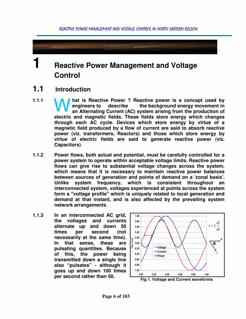
1.1.1 hat is Reactive Power ? Reactive power is a concept used by engineers to describe the background energy movement in an Alternating Current (AC) system arising from the production of
electric and magnetic fields. These fields store energy which changes through each AC cycle. Devices which store energy by virtue of a magnetic field produced by a flow of current are said to absorb reactive power (viz. transformers, Reactors) and those which store energy by virtue of electric fields are said to generate reactive power (viz. Capacitors).
1.1.2 Power flows, both actual and potential, must be carefully controlled for a power system to operate within acceptable voltage limits. Reactive power flows can give rise to substantial voltage changes across the system, which means that it is necessary to maintain reactive power balances between sources of generation and points of demand on a 'zonal basis'. Unlike system frequency, which is consistent throughout an interconnected system, voltages experienced at points across the system form a "voltage profile" which is uniquely related to local generation and demand at that instant, and is also affected by the prevailing system network arrangements.
1.1.3 In an interconnected AC grid, the voltages and currents alternate up and down 50 times per second (not necessarily at the same time). In that sense, these are pulsating quantities. Because of this, the power being transmitted down a single line also “pulsates” - although it goes up and down 100 times per second rather than 50.
W
Fig 1. Voltage and Current waveforms

REACTIVE POWER MANAGEMENT AND VOLTAGE CONTROL IN NORTH EASTERN REGION
Page 7 of 103
1.1.4 To distinguish reactive power from real power, we use the reactive power
unit called “VAR” - which stands for Volt-Ampere-Reactive (Q). Normally electric power is generated, transported and consumed in alternating current (AC) networks. Elements of AC systems supply (or produce) and consume (or absorb or lose) two kinds of power: real power and reactive power.
1.1.5 Real power accomplishes useful work (e.g., runs motors and lights lamps). Reactive power supports the voltages that must be controlled for system reliability. In AC power networks, while active power corresponds to useful work, reactive power supports voltage magnitudes that are controlled for system reliability, voltage stability, and operational acceptability.
1.1.6 VAR Management? It is defined as the control of generator voltages, variable transformer tap settings, compensation, switchable shunt capacitor and reactor banks plus allocation of new shunt capacitor and reactor banks in a manner that best achieves a reduction in system losses and/or voltage control.
1.1.7 Although active power can be transported over long distances, reactive power is difficult to transmit, since the reactance of transmission lines is often 4 to 10 times higher than the resistance of the lines. When the transmission system is heavily loaded, the active power losses in the transmission system are also high. Reactive power (vars) is required to maintain the voltage to deliver active power (watts) through transmission lines. When there is not enough reactive power, the voltage sags down and it is not possible to push the power demanded by loads through the lines. Reactive power supply is necessary in the reliable operation of AC power systems. Several recent power outages worldwide may have been a result of an inadequate reactive power supply which subsequently led to voltage collapse.
1.1.8 Voltage and current may not pulsate up and down at the same time. When the voltage and current do go up and down at the same time, only real power is transmitted. When the voltage and current go up and down at different times, reactive power is also gets transmitted. How much reactive power and
which direction it is flowing on a transmission line depend on how different these two items are.
Fig 2. Power Triangle

REACTIVE POWER MANAGEMENT AND VOLTAGE CONTROL IN NORTH EASTERN REGION
Page 8 of 103
Although AC voltage and current pulsate at the same frequency, they peak at a different time. Power is the algebraic product of voltage and current. Over a cycle, power has an average value, called real power (P), measured in volt-amperes, or watts. There is also a portion of power with zero average value that is called reactive power (Q), measured in volt-amperes reactive, or vars. The total power is called apparent power or Complex power, measured in volt-amperes, or VA.
1.2 Analogy of Reactive Power
1.2.1 Why an analogy? Reactive Power is an essential aspect of the electricity system, but one that is difficult to comprehend by a lay man. The horse and the boat analogy best describe the Reactive Power aspect.
Visualize a boat on a canal, pulled by a horse on the bank of the canal.
In actual the horse is not in front of the boat to do a meaningful work of pulling it in a straight path. Due to the balancing compensation by the rudder of the boat, the boat is made to move in a straight manner rather deviating towards the bank. This is in line with the understanding of the reactive power.
W
Fig 3. Boat pulled by a Horse Fig 4. Direction of pull
Fig 5. Vector representation of the analogy

REACTIVE POWER MANAGEMENT AND VOLTAGE CONTROL IN NORTH EASTERN REGION
Page 9 of 103
1.2.1 In the horse and boat analogy, the horse’s objective (real power) is to move the boat straightly. The fact that the rope is being pulled from the flank of the horse and not straight behind it, limits the horse’s capacity to deliver real work of moving straightly. Therefore, the power required to keep the boat steady in navigating straightly is delivered by the rudder movement (reactive power). Without reactive power there can be no transfer of real power, likewise without the support of rudder, the boat cannot move in a straight line.
1.2.2 Reactive power is like the bouncing up and down that happens when we
walk on a trampoline. Because of the nature of the trampoline, that up-down bouncing is an essential part of our forward movement across the trampoline, even though it appears to be movement in the opposite direction.
1.2.3 Reactive power and real power work together in the way that’s illustrated very well by the labyrinth puzzle, LABYRINTSPEL:
The description of the puzzle begins to show why this game represents the relationship between real and reactive power:
The intent is to manipulate a steel ball (1.2cm in diameter) through the maze by rotating the knobs – without letting the ball fall into one of the holes before it reaches the end of the maze. If a ball does fall prematurely into a hole, a slanted floor inside the box returns the ball to the user in the trough on the lower right corner of the box.
1.2.4 The Objective is to twist the two knobs to adjust the angle of the platform
in two directions, in order to keep the ball rolling through the maze without falling into any holes. Those twists are REACTIVE POWER, which helps propel the real power through to its ultimate goal, which is delivery to the user. Without reactive power, ball falls into holes along the way, which are NETWORK failures.
1.2.5 Both of these examples illustrate how important it is to understand the system and how it works in order to meet our objectives effectively. In the LABYRINTSPEL game, if the structure of the system is not taken into account, winning would be really easy because one knob would be turned
Fig 6. LABYRINTSPEL

REACTIVE POWER MANAGEMENT AND VOLTAGE CONTROL IN NORTH EASTERN REGION
Page 10 of 103
all the way in one direction, and the other knob all the way in the other direction, and the ball would merely roll across the platform. If that’s the model how electricity works, then that would deliver the electrons to the end user in the form of real power. But in the game, on the trampoline, and in the electric power network, the system has more going on that means it’s essential to do things that seem counterintuitive, like bouncing up and down on the trampoline or turning the platform in the game towards west to avoid the hole to the east, even though we have to go east to win.
1.2.6 In electric power, the counterintuitive thing about reactive power is to use some power along the path to balance the flow of electrons and the circuits. Otherwise, the electricity just flows from the generator to the largest consumer (that’s Kirchhoff’s law, basically). In this sense, reactive power is like water pressure in a water network.
1.2.7 LABYRINTSPEL game and the trampoline are good examples that they capture the fact that mathematically, real power and reactive power are pure conjugates.
1.3 Understanding Vectorially
1.3.1 In practice circuits are invariably combinations of resistance, inductance and capacitance. The combined effect of these impedances to the flow of current is most easily assessed by expressing the power flows as vectors that show the angular relationship between the powers waveforms associated with each type of impedance. Figure 7 shows how the vectors can be resolved to determine the net capacity of the circuit needed to transfer the power requirements of the connected equipment.
1.3.2 The useful power that can be drawn from the electricity distribution system is represented by the vertical vector in the diagram and is measured in kilowatts (kW).The reactive or wattless power that is a consequence of the inductive load in the circuit is represented by the horizontal vector to the right and the reactive power attributable to the circuit capacitance by the horizontal vector to the left. These are measured in kilovars (kVAr).
Fig 7. Vector representation

REACTIVE POWER MANAGEMENT AND VOLTAGE CONTROL IN NORTH EASTERN REGION
Page 11 of 103
1.3.3 The resolution of these vectors, which is the diagonal vector in the
diagram is the capacity required to transmit the active power, and is measured in kilovolts-ampere (kVA). The ratio of the kW to kVA is the cosine of the angle in the diagram shown as theta, and is referred to as the “power factor”.
1.3.4 When the net impedance of the circuit is solely resistance, so that the inductance and capacitance exactly cancel each other out, then the angle theta becomes zero and the circuit has a power factor of unity. The circuit is now operating at its highest efficiency for transferring useful power. However, as a net reactive power emerges the angle theta starts to increase and its cosine falls.
1.3.5 At low power factors the magnitude of the kVA vector is significantly greater than the real power or kW vector. Since distribution assets such as cables, lines and transformers must be sized to meet the kVA requirement, but the useful power drawn by the customer is the kW component, a significant cost emerges from having to over-size the distribution system to accommodate the substantial amount of reactive power that is associated with the active power flow.
1.4 Voltage Stability
1.4.1 Power flows, both actual and potential, must be carefully controlled for a power system to operate within acceptable voltage limits and vice versa. Not only is reactive power necessary to operate the transmission system reliably, but it can also substantially improve the efficiency with which real power is delivered to customers. Increasing reactive power production at certain locations (usually near a load center) can sometimes alleviate transmission constraints and allow cheaper real power to be delivered into a load pocket.
1.4.2 Voltage control (keeping voltage within defined limits) in an electric power system is Important for proper operation of electric power equipment and saving it from imminent damage, to reduce transmission losses and to maintain the ability of the system to withstand disturbances and prevent voltage collapse. In general terms, decreasing reactive power causes voltages to fall, while increasing reactive power causes voltages to rise. A voltage collapse occurs when the system is trying to serve much more load than the voltage can support.
1.4.3 As voltage drops, current must increase to maintain the power supplied, causing the lines to consume more reactive power and the voltage to drop further. If current increases too much, transmission lines trip, or go off-line, overloading other lines and potentially causing cascading

REACTIVE POWER MANAGEMENT AND VOLTAGE CONTROL IN NORTH EASTERN REGION
Page 12 of 103
failures. If voltage drops too low, some generators will automatically disconnect to protect themselves.
1.4.4 Usually the causes of under – voltages are:
• Overloading of supply transformers
• Inadequate short circuit level in the point of supply
• Excessive voltage drop across a long feeder • Poor power factor of the connected load
• Remote system faults , while they are being cleared
• Interval in re-closing of an auto-reclosure
• Starting of large HP induction motors
1.4.5 If the declines continue, these voltage reductions cause additional elements to trip, leading to further reduction in voltage and loss of load. The result is a progressive and uncontrollable decline in voltage, all because the power system is unable to provide the reactive power required to supply the reactive power demand.
1.5 Voltage Collapse
1.5.1 When voltages in an area are significantly low or blackout occurs due to the cascading events accompanying voltage instability, the problem is considered to be a voltage collapse phenomenon. Voltage collapse normally takes place when a power system is heavily loaded and/or has limited reactive power to support the load. The limiting factor could be the lack of reactive power (SVC and generators hit limits) production or the inability to transmit reactive power through the transmission lines.
1.5.2 The main limitation in the transmission lines is the loss of large amounts
of reactive power and also line outages, which limit the transfer capacity of reactive power through the system.
1.5.3 In the early stages of analysis, voltage collapse was viewed as a static problem but it is now considered to be a non linear dynamic phenomenon. The dynamics in power systems involve the loads, and voltage stability is directly related to the loads. Hence, voltage stability is also referred to as load stability.
1.5.4 There are other factors which also contribute to voltage collapse, and are as below:
• Increase in load • Action of tap changing transformers
• Load recovery dynamics
REACTIVE POWER MANAGEMENT AND VOLTAGE CONTROL IN NORTH EASTERN REGION
Page 13 of 103
All these factors play a significant part in voltage collapse as they effect the transmission, consumption, and generation of reactive power.
Usually voltage stability is categorized into two parts
• Large disturbance voltage stability
• Small disturbance voltage stability
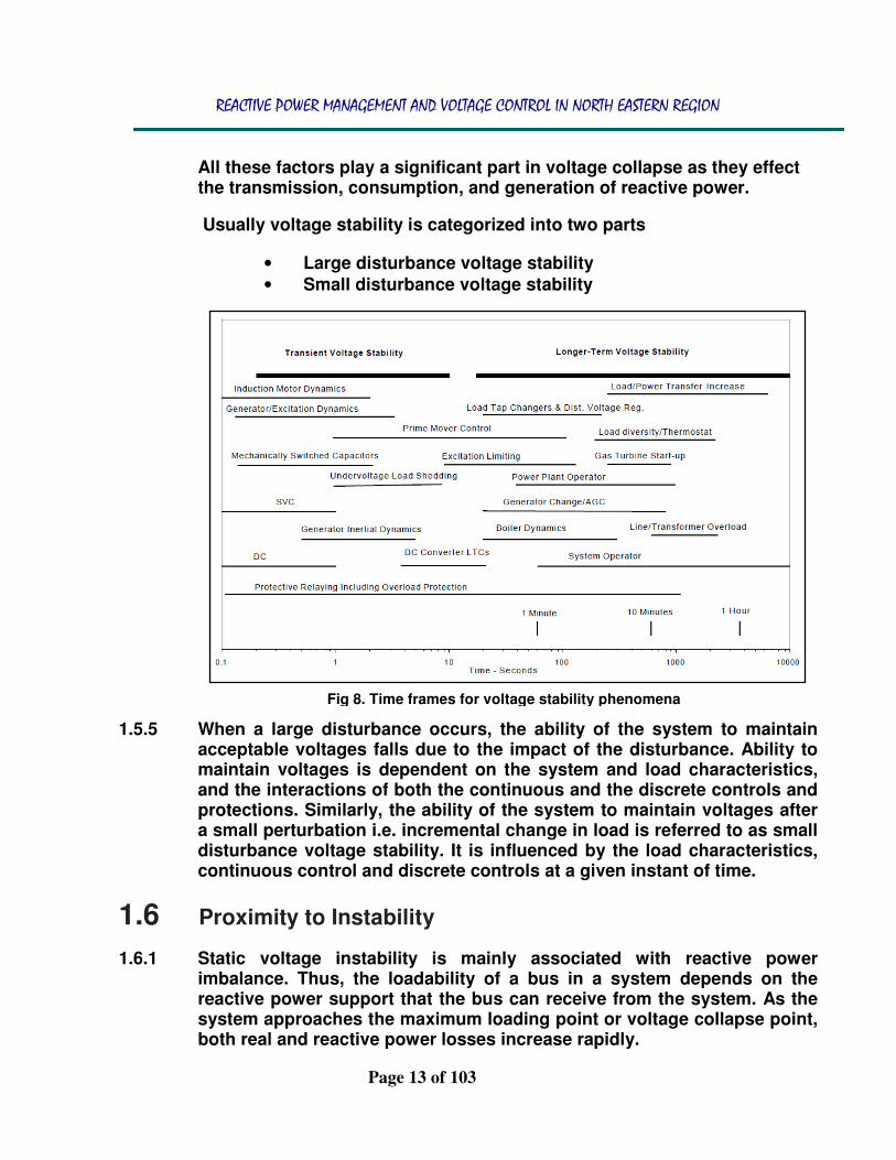
1.5.5 When a large disturbance occurs, the ability of the system to maintain acceptable voltages falls due to the impact of the disturbance. Ability to maintain voltages is dependent on the system and load characteristics, and the interactions of both the continuous and the discrete controls and protections. Similarly, the ability of the system to maintain voltages after a small perturbation i.e. incremental change in load is referred to as small disturbance voltage stability. It is influenced by the load characteristics, continuous control and discrete controls at a given instant of time.
1.6 Proximity to Instability
1.6.1 Static voltage instability is mainly associated with reactive power imbalance. Thus, the loadability of a bus in a system depends on the reactive power support that the bus can receive from the system. As the system approaches the maximum loading point or voltage collapse point, both real and reactive power losses increase rapidly.
Fig 8. Time frames for voltage stability phenomena

REACTIVE POWER MANAGEMENT AND VOLTAGE CONTROL IN NORTH EASTERN REGION
Page 14 of 103
1.6.2 Therefore, the reactive power supports have to be locally adequate. With
static voltage stability, slowly developing changes in the power system occur that eventually lead to a shortage of reactive power and declining voltage.
1.6.3 This phenomenon can be seen from
a plot of power transferred versus voltage at the receiving end. These plots are popularly referred to as P–V curves or ‘Nose’ curves. As power transfer increases, the voltage at the receiving end decreases. In the fig(9) eventually, a critical (nose) point, the point at which the system reactive power is out of usage, is reached where any further increase in active power transfer will lead to very rapid decrease in voltage magnitude.
1.6.4 Before reaching the critical point, a large voltage drop due to heavy reactive power losses is observed. The only way to save the system from voltage collapse is to reduce the reactive power load or add additional reactive power prior to reaching the point of voltage collapse.
• These are curves drawn between V and P of a critical bus at a constant load power factor.
• These are produced by using a series of power flow solutions for different load levels.
• At the knee point or the nose point of the V-P curve, the voltage drops rapidly with an increase in the load demand.
• Power flow solution fails to converge beyond this limit which indicates the instability.
1.7 Reactive Reserve Margin
1.7.1 The amount of unused available capability of reactive power static as well as dynamic in the system (at peak load for a utility system) as a percentage of total capability is known as Reactive reserve margin.
1.7.2 Voltage collapse normally occurs when sources producing reactive
power reach their limits i.e. generators, SVCs or shunt reactors, and there is not much reactive power to support the load. As reactive power is
Knee
point
∆v
Fig 9. PV curve and Voltage stability margin under different conditions

REACTIVE POWER MANAGEMENT AND VOLTAGE CONTROL IN NORTH EASTERN REGION
Page 15 of 103
directly related to voltage collapse, it can be used as a measure of voltage stability margin.
1.7.3 The voltage stability margin can be defined as a measure of how close the system is to voltage instability, and by monitoring the reactive reserves in the power system, proximity to voltage collapse can be monitored.
1.7.4 In case of reactive reserve criteria, the reactive power reserve of an
individual or group of VAr sources must be greater than some specified percentage (x %) of their reactive power output under all contingencies. The precincts where reactive power reserves were exhausted would be identified as critical areas.
1.7.5 Reactive power requirements over and above those which occur naturally are provided by an appropriate combination of reactive source/devices which are normally classified as static and dynamic devices.
• STATIC SOURCES: Static sources are typically transmission and distribution equipments such as Capacitors and Reactors that are relatively static and can respond to the changes in voltage – support requirements only slowly and in discrete steps. Devices are inexpensive, but the associated switches, control, and communications, and their maintenance, can amount to as much as one third of the total operations and maintenance budget of a distribution system.
• DYNAMIC SOURCES: It includes pure reactive power compensators like synchronous condensers, Synchronous generators and solid-state devices such as FACTS, SVC, STATCOM, D-VAR, and SuperVAR which are normally dynamic and can respond within cycles to changing reactive power requirement. These are typically considered as transmission service devices.
1.7.6 Static devices typically have lower capital costs than dynamic devices, and from a system point of view, they are used to provide normal or intact-system voltage support and to adapt to slowly changing conditions, such as daily load cycles and scheduled transactions. By contrast, dynamic reactive power sources must be deployed to allow the transmission system to respond to rapidly changing conditions on the transmission system, such as sudden loss of generators or transmission facilities. An appropriate combination of both static and dynamic resources is needed to ensure reliable operation of the transmission system at an appropriate level of costs.
REACTIVE POWER MANAGEMENT AND VOLTAGE CONTROL IN NORTH EASTERN REGION
Page 16 of 103
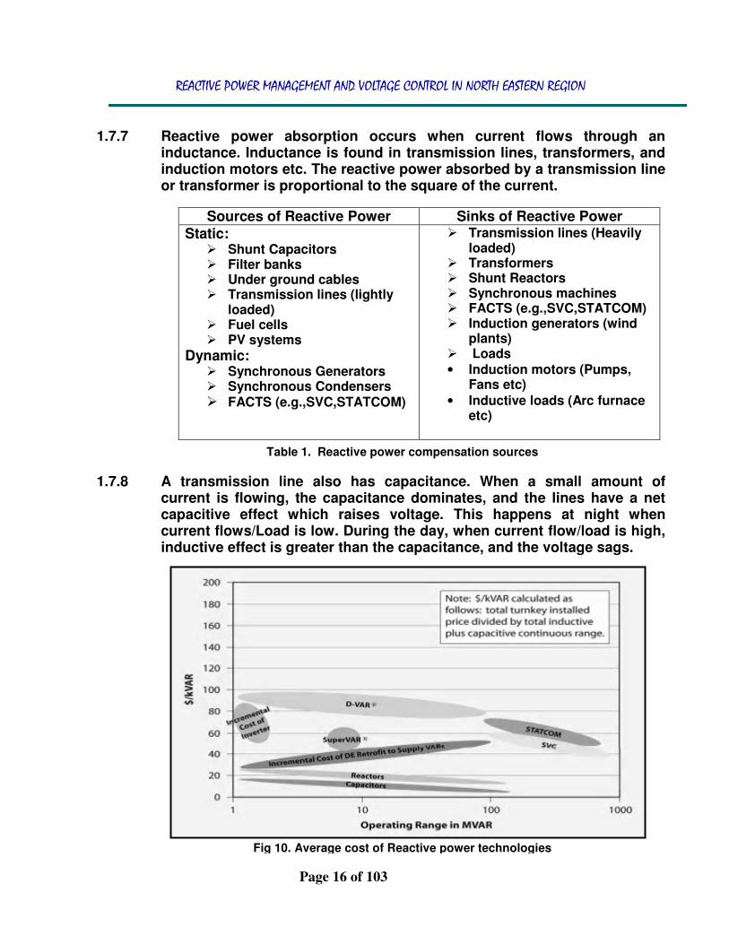
1.7.7 Reactive power absorption occurs when current flows through an
inductance. Inductance is found in transmission lines, transformers, and induction motors etc. The reactive power absorbed by a transmission line or transformer is proportional to the square of the current.
Sources of Reactive Power Sinks of Reactive Power Static:
� Shunt Capacitors � Filter banks � Under ground cables � Transmission lines (lightly
loaded) � Fuel cells � PV systems
Dynamic: � Synchronous Generators � Synchronous Condensers � FACTS (e.g.,SVC,STATCOM)
� Transmission lines (Heavily loaded)
� Transformers � Shunt Reactors � Synchronous machines � FACTS (e.g.,SVC,STATCOM) � Induction generators (wind
plants) � Loads • Induction motors (Pumps,
Fans etc) • Inductive loads (Arc furnace
etc)
1.7.8 A transmission line also has capacitance. When a small amount of current is flowing, the capacitance dominates, and the lines have a net capacitive effect which raises voltage. This happens at night when current flows/Load is low. During the day, when current flow/load is high, inductive effect is greater than the capacitance, and the voltage sags.
Fig 10. Average cost of Reactive power technologies
Table 1. Reactive power compensation sources

REACTIVE POWER MANAGEMENT AND VOLTAGE CONTROL IN NORTH EASTERN REGION
Page 17 of 103
1.8 NER GRID – Overview
1.8.1 NER grid with a maximum peak requirement of around 2100 MW and installed capacity of 2746 MW caters to the seven north eastern states. It is synchronously connected with NEW GRID through 400 kV QUAD/C BONGAIGAON – NEW SILIGURI, 220 kV D/C BIRPARA – SALAKATI and internationally through 132 kV SALAKATI – GELYPHU(Bhutan) and 132 kV Rangia - Deothang. The bottle neck of operating the NER grid arises because of the brittle back bone network of about 7666 Ckt Kms of 132 KV lines, 2084 Ckt Kms of 400 KV lines and 2925 Ckt Kms of 220 KV lines compared to other regional grids.
1.8.2 Almost 50% of the total NER load is spread out in 132 kV pocket of
southern part of NER which were without the direct support of major EHV trunk lines. This part of the network was highly sensitive and was susceptible to grid disturbance in the past and demanded more operational acumen. Increase in the loading of major 132 kV trunk lines, in particular 132 kV DIMAPUR – IMPHAL S/C,132 kV JIRIBAM – LOKTAK S/C and 132 kV BADARPUR – KHLIEHRIAT S/C in peak hours has led to
Fig 11. NER Grid map

REACTIVE POWER MANAGEMENT AND VOLTAGE CONTROL IN NORTH EASTERN REGION
Page 18 of 103
many a grid incidents in the past in the form of cascade tripping accompanied by voltage sag. However, with system augmentation grid incidence in this part of the grid has become a matter of past.
1.8.3 NER system has been strengthened with the commissioning of 400 kV
AZARA – Silchar S/C, 400/220 kV 315 MVA ICT I & II, 400 kV Balipara – Bongaigaon III & IV, 400 kV Bongaigaon – Siliguri III & IV. With the availability of greater options, grid operation has been smooth and grid parameters were maintained within the prescribe IEGC limits.
1.8.4 Relationship between frequency and voltage is a well known fact. Studies
have revealed that though voltage is a localized factor, it is directly affected by the frequency which is a notional factor. Any lopsidedness in the demand/generation side leading to fluctuations in NEW grid frequency affects NER grid immensely, in particular the voltage profile of the grid, leading to sagging and swelling of voltage heavily during such occasions. Ironically, NER was synchronously connected with NEW grid for stretching the transmission capability to reduce the load – generation mismatch of the country.
1.8.5 FSC’s have been integrated with the NER system in the 400 kV Balipara –
Bongaigaon III & IV at Balipara end . It is needed to be seen how far the +/-800 KV HVDC project in NER which is in the execution stage will help in maintaining a healthy voltage profile in the region with its reactive reserve support in the form of filters and capacitor banks.
1.8.6 Presently NER Grid is supported by 2383 MVAr from shunt reactors and 273 MVAr from shunt capacitors spread across the region.
1.8.7 Skewness in the location of hydro stations and load centers in NER is another obstacle which aggravates the voltage problem further. Lines are long and pass through difficult terrains to the load centers. Northern part of NER grid which is well supported by some strong 400 KV and 220 KV network faces high voltage regime during lean hydro period as the corridor is not fully utilized and is usually lightly loaded. Supports from hydro stations in condenser mode are not available for containing low voltage conditions. D curve optimization is yet to be realized fully due to technical glitches.
1.8.8 Reactive power management and voltage control are two aspects of a single activity that both supports reliability and facilitates commercial transaction across transmission network. Controlling reactive power flow can reduce losses and congestion on the transmission system.

REACTIVE POWER MANAGEMENT AND VOLTAGE CONTROL IN NORTH EASTERN REGION
Page 19 of 103
1.8.9 Operationally in NER, Voltage is normally controlled by managing production and absorption of reactive power in real time :
• Switching in and out of Line reactance compensators such as capacitors and shunt reactors (Line/Bus Reactors) as and when system demands in co-operation with the constituents and the CTU.
• Circuit switching: Mostly one circuit of the lightly loaded d/c line is kept open keeping in mind the n-1 criterion during high voltage and high frequency period. Voltage differences as well as fault level of stations are taken into account before any switching operation of circuits. Fault levels of major substation in NER are as below:
Three Phase Fault Level (Minimum Fault Level with IEC) of Major Sub-Stations of NER
Bus
Off Peak Peak
3 ϕ Fault
Current in kA 3 ϕ Fault MVA
3 ϕ Fault
Current in kA 3 ϕ Fault MVA
400 kV Substations
Azara (Mirza) 3.2 2238 3.2 2217
Balipara 5.9 4093 6.0 4178
Bongaigaon 8.2 5716 8.1 5606
Byrnihat 3.5 2403 3.4 2384
Misa 5.6 3851 5.6 3902
Palatana 4.3 2977 4.3 2966
Ranganadi 3.8 2637 4.0 2757
Silchar 4.8 3222 4.6 3189
220 kV Substations
AGBPP
(Kathalguri) 5.6 2132 5.5 2103
Agia 6.6 2497 6.3 2418
Azara (Mirza) 6.3 2383 6.2 2355
Balipara 6.3 2397 6.4 2426
Boko 4.8 1841 4.8 1818
BTPS 9.3 3543 8.7 3306
Byrnihat 6.7 2566 6.7 2540
Dimapur (PG) 4.5 1716 4.6 1738
Kopili 8.5 3252 8.5 3238

REACTIVE POWER MANAGEMENT AND VOLTAGE CONTROL IN NORTH EASTERN REGION
Page 20 of 103
Langpi 3.8 1438 3.8 1437
Mariani (AS) 5.1 1931 5.0 1902
Mariani (PG) 3.1 1193 3.1 1189
Misa 11.9 4537 11.9 4554
NTPS 4.2 1601 4.1 1573
Salakati 9.5 3630 8.9 3377
Samaguri 9.5 3629 9.6 3643
Sarusajai 5.8 2207 5.8 2201
Tinsukia 5.0 1920 4.9 1888
132 kV Substations
Silchar 10.1 2315 9.9 2273
Badarpur 9.3 2134 9.1 2080
Khandong 8.2 1864 7.7 1772
Khlierihat 7.8 1792 6.9 1576
AGTPP (RC
Nagar) 7.5 1716 7.5 1723
Kumarghat 5.7 1303 5.7 1306
Dimapur (PG) 5.6 1273 5.7 1306
Jiribam 4.4 1006 4.5 1032
Nirjuli 4.4 1000 4.6 1047
Loktak 3.2 732 3.7 847
Haflong 3.2 734 3.2 730
Doyang 3.2 738 3.3 748
Balipara 3.1 720 3.2 735
Aizawl 2.8 646 2.8 652
• The generating units provide the basic means of voltage
control: The automatic voltage regulators (AVR) control field excitation to maintain the scheduled voltage levels at the terminals of the generators. In real time operation, connected generation should never be on reactive generation or absorption limits.
• By generation re-dispatch/rescheduling. • Regulating voltage with the help of OLTC’s.
• By load staggering/shedding.
Table 2. Fault level at important Sub-Stations of NER

REACTIVE POWER MANAGEMENT AND VOLTAGE CONTROL IN NORTH EASTERN REGION
Page 21 of 103
1.9 Reliability Improvement Due to Local Voltage Regulation
1.9.1 Local voltage regulation to a voltage schedule supplied by the utility can have a very beneficial effect on overall system reliability, reducing the problems caused by voltage dips on distribution circuits such as dimming lights, slowing or stalling motors, dropout of contactors and solenoids, and shrinking television pictures.
1.9.2 In past years a voltage drop would inherently reduce load, helping the situation. Light bulbs would dim and motors would slow down with decreasing voltage. Dimmer lights and slower motors typically draw less power, so the situation was in a certain sense self-correcting. With modern loads, this situation is changing.
1.9.3 Today many incandescent bulbs are being replaced with compact fluorescent lights, LED lamps that draw constant power as voltage decreases, and motors are being powered with adjustable-speed drives that maintain a constant speed as voltage decreases. In addition, voltage control standards are rather unspecific, and there is a tremendous opportunity for an improvement in efficiency and reliability from better voltage regulation. Capacitors supply reactive power to boost voltage, but their effect is dramatically diminished as voltage dips.
1.9.4 Capacitor effectiveness is proportional to the square of the voltage, so at 80% voltage, capacitors are only 64% as effective as they are at normal conditions. As voltage continues to drop, the capacitor effect falls off until voltage collapses. The reactive power supplied by an inverter is dynamic, it can be controlled very rapidly, and it does not drop off with a decrease in voltage. Distribution systems that allow customers to supply dynamic reactive power to regulate voltage could be a tremendous asset to system reliability and efficiency by expanding the margin to voltage collapse.
REACTIVE POWER MANAGEMENT AND VOLTAGE CONTROL IN NORTH EASTERN REGION
Page 22 of 103
2 TRANSMISSION LINES AND REACTIVE
POWER COMPENSATION
2.1 Introduction
2.1.1 In moving power from generators to loads, the transmission network introduces both real and reactive losses. Housekeeping loads at substations (such as security lighting and space conditioning) and transformer excitation losses are roughly constant (i.e., independent of the power flows on the transmission system). Transmission-line losses, on the other hand, depend strongly on the amount of power being transmitted.
2.1.2 Real-power losses arise because aluminum and copper (the materials most often used for transmission lines) are not perfect conductors; they have resistance. The consumption of reactive power by transmission lines increases with the square of current i.e., the transmission of reactive power requires an additional demand for reactive power in the system components.
2.1.3 The reactive-power nature of transmission lines is associated with the geometry of the conductors themselves (primarily the radius of the conductor) and the geometry of the conductor configuration (the distances between each conductor and ground and the distances among conductors).
2.1.4 The reactive-power behavior of transmission lines is complicated by their inductive and capacitive characteristics. At low line loadings, the capacitive effect dominates, and generators and transmission-related reactive equipment must absorb reactive power to maintain line voltages within their appropriate limits. On the other hand, at high line loadings, the inductive effect dominates, and generators, capacitors, and other reactive devices must produce reactive power
2.1.5 The thermal limit is the loading point (in MVA) above which real power losses in the equipment will overheat and damage the equipment. Most transmission elements (e.g., conductors and transformers) have normal thermal limits below which the equipment can operate indefinitely without any damage. These types of equipment also have one or more emergency limits to which the equipment can be loaded for several hours with minimal reduction in the life of the equipment.

REACTIVE POWER MANAGEMENT AND VOLTAGE CONTROL IN NORTH EASTERN REGION
Page 23 of 103
2.1.6 If uncompensated, these line losses reduce the amount of real power that
can be transmitted from generators to loads. Transmission-line capacity decreases as the line length increases if there is no voltage support (injection or absorption of reactive power) on the line. At short distances, the line’s capacity is limited by thermal considerations; at intermediate distances the limits are related to voltage drop; and beyond roughly 300 to 350 miles, stability limits dominate.
2.2 Surge Impedance Loading (SIL)
2.2.1 Transmission lines and cables generate and consume reactive power at the same time. The reactive power generation is almost constant, because the voltage of the line is usually constant, and the line’s reactive power consumption depends on the current or load connected to the line that is variable. So at the heavy load conditions transmission lines consume reactive power, decreasing the line voltage, and in the low load conditions – generate, increasing line voltage.
2.2.2 The case when line’s reactive power produced by the line capacitance is equal to the reactive power consumed by the line inductance is called natural loading or surge impedance loading (SIL) , meaning that the line provides exactly the amount of MVAr needed to support its voltage. The balance point at which the inductive and capacitive effects cancel each other is typically about 40% of the line’s thermal capacity. Lines loaded above SIL consume reactive power, while lines loaded below SIL supply reactive power.
2.2.3 A 400 kV, line generates approximately 55 MVAR per 100 km/Ckt, when it is idle charged due to line charging susceptance. This implies a 300 km line generates about 165 MVAR when it is idle charged.
2.3 Shunt Compensation in Line
2.3.1 Normally there are two types of shunt reactors – Line reactor and bus reactor. Line reactor’s functionality is to avoid the switching and load rejection over voltages where as Bus reactors are used to avoid the steady state over voltage during light load conditions.
2.3.2 The degree of compensation is decided by an economic point of view between the capitalized cost of compensator and the capitalized cost of reactive power from supply system over a period of time. In practice a compensator such as a bank of capacitors (or inductors) can be divided into parallel sections, each Switched separately, so that discrete changes

REACTIVE POWER MANAGEMENT AND VOLTAGE CONTROL IN NORTH EASTERN REGION
Page 24 of 103
in the compensating reactive power may be made, according to the requirements of the load.
2.3.3 Reasons for the application of shunt capacitor units are :
• Increase voltage level at the load
• Improves voltage regulation if the capacitor units are properly switched.
• Reduces I2R power loss in the system because of reduction in current.
• Increases power factor of the source generator.
• Decrease kVA loading on the source generators and circuits to relieve an overloaded condition or release capacity for additional load growth.
• By reducing kVA loading on the source generators additional kilowatt loading may be placed on the generation if turbine capacity is available.
2.4 Line loading as function of Line Length and Compensation
2.4.1 The operating limits for transmission lines may be taken as minimum of thermal rating of conductors and the maximum permissible line loadings derived from St. Clair’s curve. SIL given in table above is for uncompensated line. If k is the compensation then:
• For a shunt compensated line:
SIL modified =SIL x √ (1-k)
• For a series compensated line:
SIL modified=SIL/ √ (1- k)
Further to take into account the line length one needs to multiple the modified SIL with the multiplying factor derived from St. Clair's curve.The derived steady state limit for a line would be = SIL modified x factor from St. Clair's curve.
Fig 12. SIL VS Compensation

REACTIVE POWER MANAGEMENT AND VOLTAGE CONTROL IN NORTH EASTERN REGION
Page 25 of 103
REACTIVE POWER MANAGEMENT AND VOLTAGE CONTROL IN NORTH EASTERN REGION
Page 26 of 103
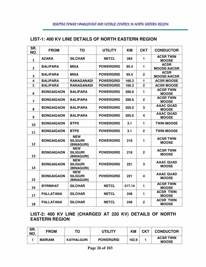
LIST-1: 400 KV LINE DETAILS OF NORTH EASTERN REGION SR. NO.
FROM TO UTILITY KM CKT CONDUCTOR
1 AZARA SILCHAR NETCL 264 1
ACSR TWIN MOOSE
2 BALIPARA MISA POWERGRID 95.4 1
ACSR MOOSE/AACSR
3 BALIPARA MISA POWERGRID 95.4 2
ACSR MOOSE/AACSR
4 BALIPARA RANAGANADI POWERGRID 166.3 1 ACSR MOOSE
5 BALIPARA RANAGANADI POWERGRID 166.3 2 ACSR MOOSE
6 BONGAIGAON BALIPARA POWERGRID 289.8 1
ACSR TWIN MOOSE
7 BONGAIGAON BALIPARA POWERGRID 289.8 2
ACSR TWIN MOOSE
8 BONGAIGAON BALIPARA POWERGRID 305.0 3
AAAC QUAD MOOSE
9 BONGAIGAON BALIPARA POWERGRID 305.0 4
AAAC QUAD MOOSE
10 BONGAIGAON BTPS POWERGRID 3.1 1 TWIN MOOSE
11 BONGAIGAON BTPS POWERGRID 3.1 2 TWIN MOOSE
12
BONGAIGAON NEW SILIGURI (BINAGURI)
POWERGRID 218 1 ACSR TWIN
MOOSE
13
BONGAIGAON NEW SILIGURI (BINAGURI)
POWERGRID 218 2 ACSR TWIN
MOOSE
14
BONGAIGAON NEW SILIGURI (BINAGURI)
POWERGRID 221 3 AAAC QUAD
MOOSE
15
BONGAIGAON NEW SILIGURI (BINAGURI)
POWERGRID 221 4 AAAC QUAD
MOOSE
16 BYRNIHAT SILCHAR NETCL 217.14 1
ACSR TWIN MOOSE
17 PALLATANA SILCHAR NETCL 246 1
ACSR TWIN MOOSE
18 PALLATANA SILCHAR NETCL 246 2
ACSR TWIN MOOSE
LIST-2: 400 KV LINE (CHARGED AT 220 KV) DETAILS OF NORTH EASTERN REGION
SR. NO.
FROM TO UTILITY KM CKT CONDUCTOR
1 MARIANI KATHALGURI POWERGRID 162.9 1 ACSR TWIN
MOOSE

REACTIVE POWER MANAGEMENT AND VOLTAGE CONTROL IN NORTH EASTERN REGION
Page 27 of 103
2 MISA NEW MARIANI
POWERGRID 222.7 1 ACSR TWIN
MOOSE
3 MISA MARIANI POWERGRID 220.0 1 ACSR TWIN
MOOSE
4 NEW MARIANI
KATHALGURI POWERGRID 160.5 1 ACSR TWIN
MOOSE
LIST-3: 400 KV LINE CHARGED AT 132 KV SR. NO.
FROM TO UTILITY KM CKT CONDUCTOR
1 PALATANA SURJAMANINAGAR
POWERGRID 37 1 ACSR TWIN
MOOSE
LIST-4: 220 KV LINE DETAILS OF NORTH EASTERN REGION
SR. NO.
FROM TO UTILITY KM CKT CONDUCTOR
1 AGIA AZARA AEGCL 1.0 1 AAAC ZEBRA
2 AGIA BOKO AEGCL 70.0 1 AAAC ZEBRA
3 AGIA BTPS AEGCL 67.0 1 AAAC ZEBRA
4 AGIA BTPS AEGCL 67.0 2 AAAC ZEBRA
5 AZARA BOKO AEGCL 38 1 AAAC ZEBRA
6 AZARA SARUSAJAI AEGCL 48 1 AAAC ZEBRA
7 BALIPARA SAMAGURI AEGCL 55.0 1 SINGLE ZEBRA
8 BONGAIGAON SALAKATI POWERGRID 5.4 1 SINGLE ZEBRA
9 DEOMALI KATHALGURI
ARUNACHAL PRADESH
19.0 1 SINGLE ZEBRA
10 KATHALGURI TINSUKIA AEGCL 22.0 1 SINGLE ZEBRA
11 KATHALGURI TINSUKIA AEGCL 22.0 2 SINGLE ZEBRA
12 MISA DIMAPUR POWERGRID 121.9 1 ACSR ZEBRA
13 MISA DIMAPUR POWERGRID 121.9 2 ACSR ZEBRA
14 MISA KOPILI POWERGRID 72.8 1 ACSR ZEBRA
15 MISA KOPILI POWERGRID 72.8 2 ACSR ZEBRA
16 MISA KOPILI POWERGRID 75.9 3 AAAC ZEBRA
17 MISA BYRNIHAT MeECL 115.0 1 SINGLE ZEBRA
18 MISA BYRNIHAT MeECL 115.0 2 SINGLE ZEBRA
19 NTPS TINSUKIA AEGCL 40.0 1 SINGLE ZEBRA
20 NTPS TINSUKIA AEGCL 40.0 2 SINGLE ZEBRA
21 SALAKATI
BIRPARA (ER)
POWERGRID 160.0 1 SINGLE ZEBRA
22 SALAKATI
BIRPARA (ER)
POWERGRID 160.0 2 SINGLE ZEBRA
23 SALAKATI BTPS AEGCL 2.7 1 ACSR ZEBRA
24 SALAKATI BTPS POWERGRID 2.7 2 ACSR ZEBRA
REACTIVE POWER MANAGEMENT AND VOLTAGE CONTROL IN NORTH EASTERN REGION
Page 28 of 103
25 SAMAGURI
JAWAHARNAGAR
AEGCL 120 1 AAAC ZEBRA
26 SAMAGURI MARIANI AEGCL 164.0 1 AAAC DEER
27 SAMAGURI MISA POWERGRID 34.4 1 ACSR ZEBRA
28 SAMAGURI MISA POWERGRID 34.4 2 ACSR ZEBRA
29 SARUSAJAI
JAWAHARNAGAR
AEGCL 10 1 AAAC ZEBRA
30 SARUSAJAI LANGPI AEGCL 108.0 1 AAAC ZEBRA
31 SARUSAJAI SAMAGURI AEGCL 124.0 2 AAAC ZEBRA
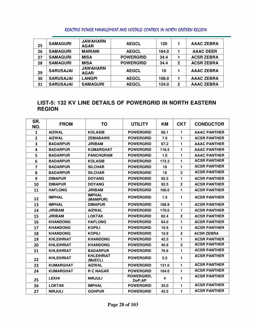
LIST-5: 132 KV LINE DETAILS OF POWERGRID IN NORTH EASTERN REGION
SR. NO.
FROM TO UTILITY KM CKT CONDUCTOR
1 AIZWAL KOLASIB POWERGRID 66.1 1 AAAC PANTHER
2 AIZWAL ZEMABAWK POWERGRID 7.0 1 ACSR PANTHER
3 BADARPUR JIRIBAM POWERGRID 67.2 1 AAAC PANTHER
4 BADARPUR KUMARGHAT POWERGRID 118.5 1 AAAC PANTHER
5 BADARPUR PANCHGRAM POWERGRID 1.0 1 AAAC PANTHER
6 BADARPUR KOLASIB POWERGRID 172.3 1 ACSR PANTHER
7 BADARPUR SILCHAR POWERGRID 19 1 ACSR PANTHER
8 BADARPUR SILCHAR POWERGRID 19 2 ACSR PANTHER
9 DIMAPUR DOYANG POWERGRID 92.5 1 ACSR PANTHER
10 DIMAPUR DOYANG POWERGRID 92.5 2 ACSR PANTHER
11 HAFLONG JIRIBAM POWERGRID 100.0 1 ACSR PANTHER
12 IMPHAL
IMPHAL (MANIPUR)
POWERGRID 1.5 1 ACSR PANTHER
13 IMPHAL DIMAPUR POWERGRID 168.9 1 ACSR PANTHER
14 JIRIBAM AIZWAL POWERGRID 170.0 1 ACSR PANTHER
15 JIRIBAM LOKTAK POWERGRID 82.4 2 ACSR PANTHER
16 KHANDONG HAFLONG POWERGRID 64.0 1 ACSR PANTHER
17 KHANDONG KOPILI POWERGRID 10.9 1 ACSR PANTHER
18 KHANDONG KOPILI POWERGRID 10.9 2 ACSR ZEBRA
19 KHLEIHRIAT KHANDONG POWERGRID 42.5 1 ACSR PANTHER
20 KHLEIHRIAT KHANDONG POWERGRID 40.9 2 ACSR PANTHER
21 KHLEIHRIAT BADARPUR POWERGRID 76.6 1 ACSR PANTHER
22 KHLEIHRIAT
KHLEIHRIAT (MeECL)
POWERGRID 5.5 1 ACSR PANTHER
23 KUMARGHAT AIZWAL POWERGRID 131.0 1 ACSR PANTHER
24 KUMARGHAT R C NAGAR POWERGRID 104.0 1 ACSR PANTHER
25 LEKHI NIRJULI
POWERGRID, DoP,AP
4 1 ACSR PANTHER
26 LOKTAK IMPHAL POWERGRID 35.0 1 ACSR PANTHER
27 NIRJULI GOHPUR POWERGRID 42.5 1 ACSR PANTHER

REACTIVE POWER MANAGEMENT AND VOLTAGE CONTROL IN NORTH EASTERN REGION
Page 29 of 103
28 PALLATANA SURAJMANI NAGAR
37 1 ACSR PANTHER
29 PANCHGRAM BADARPUR POWERGRID 1.0 1 AAAC PANTHER
30 R C NAGAR AGARTALA POWERGRID 8.4 1 ACSR PANTHER
31 R C NAGAR AGARTALA POWERGRID 8.4 2 ACSR PANTHER
32 RANGANADI LEKHI
POWERGRID, DoP,AP
18 3 ACSR PANTHER
33 RANGANADI ZIRO POWERGRID 44.5 1 ACSR PANTHER
34 RANGIA MOTONGA POWERGRID 49 1 ACSR PANTHER
35 SALAKATI GELYPHU (BHUTAN)
POWERGRID 49.2 1 ACSR PANTHER
36 SILCHAR SRIKONA POWERGRID 1 1 ACSR PANTHER
37 SILCHAR SRIKONA POWERGRID 1 2 AAAC PANTHER
LIST-6: 132 KV LINE DETAILS OF NEEPCO IN NORTH EASTERN REGION
SR. NO.
FROM TO UTILITY KM CKT CONDUCTOR
1 BALIPARA BHALUKPANG NEEPCO 35 1 ACSR PANTHER
2 BHALUKPANG KHUPI NEEPCO 32 1 ACSR PANTHER
3 KHUPI KIMI NEEPCO 8 1 ACSR PANTHER
LIST-7: 132 KV LINE DETAILS OF AEGCL IN NORTH EASTERN REGION
SR. NO.
FROM TO UTILITY KM CKT CONDUCTOR
1 B CHARIALI GOHPUR AEGCL 51.0 1 ACSR PANTHER
2 BALIPARA DEPOTA AEGCL 28.0 1 ACSR PANTHER
3 BALIPARA GOHPUR AEGCL 106.0 1 SINGLE ZEBRA
4 BOKAJAN DIMAPUR AEGCL 5.0 1 ACSR PANTHER
5 BORNAGAR RANGIA AEGCL 86.0 1 ACSR PANTHER
6 CTPS JAGIROAD AEGCL 35.0 1 ACSR PANTHER
7 DEPOTA B CHARIALI AEGCL 57.0 1 ACSR PANTHER
8 DEPOTA SAMAGURI AEGCL 45.0 1 ACSR PANTHER
9 DHALIGAON BTPS AEGCL 22.0 1 ACSR PANTHER
10 DHALIGAON BTPS AEGCL 22.0 2 ACSR PANTHER
11 DHALIGAON NALBARI AEGCL 106.0 1 ACSR PANTHER
12 DHALIGAON BORNAGAR AEGCL 41.0 1 ACSR PANTHER
13 DHALIGAON
ASHOK PAPER MILL
AEGCL 37.0 1 ACSR PANTHER
14 DHALIGAON BRPL AEGCL 1.0 1 ACSR PANTHER
15 DIBRUGARH MORAN AEGCL 36.0 1 ACSR PANTHER
16 DIPHU SANKARDEV NGR AEGCL 72.0 1 ACSR PANTHER
17 DISPUR CTPS AEGCL 29.0 1 ACSR PANTHER

REACTIVE POWER MANAGEMENT AND VOLTAGE CONTROL IN NORTH EASTERN REGION
Page 30 of 103
18 GOHPUR N LAKHIMPUR AEGCL 77.0 1 ACSR PANTHER
19 GOHPUR N LAKHIMPUR AEGCL 77.0 1 ACSR PANTHER
20 GOLAGHAT BOKAJAN AEGCL 65.0 1 ACSR PANTHER
21 GOSAIGAON DHALIGAON AEGCL 65.0 1 ACSR PANTHER
22 GOSAIGAON GAURIPUR AEGCL 62.0 1 ACSR PANTHER
23 HAFLONG HAFLONG AEGCL 1.0 1 ACSR PANTHER
24 JAGIROAD HPC AEGCL 5.0 1 ACSR PANTHER
25 JIRIBAM PAILAPOOL AEGCL 15.0 1 ACSR PANTHER
26 JORHAT BOKAKHAT AEGCL 89.0 1 ACSR PANTHER
27 KAHELIPARA NARENGI AEGCL 12.0 1 ACSR PANTHER
28 KAHELIPARA SARUSAJAI AEGCL 4.0 1 ACSR PANTHER
29 KAHELIPARA SARUSAJAI AEGCL 4.0 2 ACSR PANTHER
30 KAHELIPARA SARUSAJAI AEGCL 4.0 3 ACSR PANTHER
31 KAHELIPARA SARUSAJAI AEGCL 4.0 4 ACSR PANTHER
32 KAHELIPARA DISPUR AEGCL 3.0 1 ACSR PANTHER
33 LANKA DIPHU AEGCL 71.6 1 ACSR PANTHER
34 LTPS NTPS AEGCL 60.0 1 ACSR PANTHER
35 LTPS NTPS AEGCL 60.0 2 ACSR PANTHER
36 LTPS NAZIRA AEGCL 22.0 1 ACSR PANTHER
37 LTPS NAZIRA AEGCL 22.0 2 ACSR PANTHER
38 LTPS MARIANI AEGCL 80.0 1 ACSR PANTHER
43 LTPS MORAN AEGCL 39.0 1 ACSR PANTHER
39 MARIANI JORHAT AEGCL 20.0 1 ACSR PANTHER
40 MARIANI JORHAT AEGCL 20.0 2 ACSR PANTHER
41 MARIANI GOLAGHAT AEGCL 45.0 1 ACSR PANTHER
42 MOKOKCHUNG MARIANI AEGCL 19.0 1 ACSR PANTHER
44 N LAKHIMPUR DHEMAJI AEGCL 63.0 1 ACSR PANTHER
45 NALBARI RANGIA AEGCL 22.0 1 ACSR PANTHER
46 NARENGI CTPS AEGCL 20.0 1 ACSR PANTHER
47 NAZIRA SIBSAGAR AEGCL 13.0 1 ACSR PANTHER
48 PANCHGRAM SRIKONA AEGCL 19.0 1 ACSR PANTHER
49 PANCHGRAM SILCHAR AEGCL 30.0 1 ACSR PANTHER
50 RANGIA SISUGRAM AEGCL 33.0 1 ACSR PANTHER
51 RANGIA SIPAJHAR AEGCL 38.0 1 ACSR PANTHER
52 RANGIA KAHELIPARA AEGCL 46.0 1 ACSR PANTHER
53 RANGIA ROWTA AEGCL 108.0 1 ACSR PANTHER
54 ROWTA DEPOTA AEGCL 72.0 1 ACSR PANTHER
55 ROWTA DEPOTA AEGCL 64.0 2 ACSR PANTHER
56 SAMAGURI SANKARDEV NGR AEGCL 61.0 1 ACSR PANTHER
57 SILCHAR DULLAVCHERRA AEGCL 50.0 1 ACSR PANTHER
58 SIPAJHAR ROWTA AEGCL 44.0 1 ACSR PANTHER
59 SISUGRAM KAHELIPARA AEGCL 12.0 1 ACSR PANTHER
60 SRIKONA PAILAPOOL AEGCL 35.0 1 ACSR PANTHER
61 TINSUKIA LEDO AEGCL 53.0 1 ACSR PANTHER
62 TINSUKIA DIBRUGARH AEGCL 53.0 1 ACSR PANTHER

REACTIVE POWER MANAGEMENT AND VOLTAGE CONTROL IN NORTH EASTERN REGION
Page 31 of 103
LIST-8: 132 KV LINE DETAILS OF MANIPUR IN NORTH EASTERN REGION
SR. NO.
FROM TO UTILITY KM CKT CONDUCTOR
1 CHURACHANDPUR KAKCHING MANIPUR 38.0 1 ACSR PANTHER
2 IMPHAL IMPHAL(PG) MANIPUR 2.3 2 ACSR PANTHER
3 IMPHAL MANIPUR KARONG MANIPUR 60.0 1 ACSR PANTHER
4 KAKCHING KONGBA MANIPUR 45.0 1 ACSR PANTHER
5 KONGBA YAINGANGPOKPI MANIPUR 33.0 1 ACSR PANTHER
6 LOKTAK NINGTHOUKONG MANIPUR 20.0 1 ACSR PANTHER
7 LOKTAK RENGPANG MANIPUR 42.0 1 ACSR PANTHER
8 NINGTHOUKONG CHURACHANDPUR MANIPUR 23.0 1 ACSR PANTHER
9 NINGTHOUKONG CHURACHANDPUR MANIPUR 23.0 2 ACSR PANTHER
10 NINGTHOUKONG IMPHAL(PG) MANIPUR 26.2 1 ACSR PANTHER
11 RENGPANG JIRIBAM MANIPUR 40.4 1 ACSR PANTHER
12 YAINGANGPOKPI IMPHAL MANIPUR MANIPUR 42.0 1 ACSR PANTHER
LIST-9: 132 KV LINE DETAILS OF TSECL IN NORTH
63 TINSUKIA NTPS AEGCL 43.0 1 ACSR PANTHER
SR. NO.
FROM TO UTILITY KM CKT CONDUCTOR
1 AGARTALA BODHJ NGR TSECL 8.0 1 ACSR PANTHER
2 AGARTALA ROKHIA TSECL 35.0 1 ACSR PANTHER
3 AGARTALA ROKHIA TSECL 35.0 2 ACSR PANTHER
4 BARAMURA GAMAITILLA TSECL 14.0 1 ACSR PANTHER
5 BODHJ NGR JIRANIA TSECL 7.0 1 ACSR PANTHER
6 DHALABIL AGARTALA TSECL 45.0 1 ACSR PANTHER
7 GAMAITILLA AMBASA TSECL 25.0 1 ACSR PANTHER
8 JIRANIA BARAMURA TSECL 15.0 1 ACSR PANTHER
9 KAMALPUR DHALABIL TSECL 32.0 1 ACSR PANTHER
10 P K BARI KAILASHOR TSECL 18.0 1 ACSR PANTHER
11 P K BARI KUMARGHAT TSECL 1.0 1 ACSR PANTHER
12 P K BARI AMBASA TSECL 45.0 1 ACSR PANTHER
13 P K BARI KAMALPUR TSECL 31.0 1 ACSR PANTHER
14 P K BARI DHARMA NAGAR TSECL 35.0 1 ACSR PANTHER
15 PALLATANA UDAIPUR TSECL 6 1 ACSR PANTHER
16 ROKHIA UDAIPUR TSECL 40.0 1 ACSR PANTHER

REACTIVE POWER MANAGEMENT AND VOLTAGE CONTROL IN NORTH EASTERN REGION
Page 32 of 103
LIST-10: 132 KV LINE DETAILS OF NAGALAND IN NORTH EASTERN
REGION
LIST-11: 132 KV LINE DETAILS OF MIZORAM IN NORTH EASTERN REGION
SR. NO.
FROM TO UTILITY KM CKT
CONDUCTOR
1 ZUANGTUI SAITUAL MIZORAM 50.0 1 ACSR PANTHER
2 SERCHIP ZUANGTUI MIZORAM 54.0 1 ACSR PANTHER
3 LUNGLEI SERCHIP MIZORAM 69.0 1 ACSR PANTHER
4 AIZWAL LUANGMUAL MIZORAM 6.7 1 ACSR PANTHER
5 BHAIRABI KOLASIB MIZORAM 30.0 1 ACSR PANTHER
LIST-12: 132 KV LINE DETAILS OF MeECL IN NORTH EASTERN REGION
SR. NO.
FROM TO UTILITY KM CKT
CONDUCTOR
1 DIMAPUR DIMAPUR (PGCIL) NAGALAND 1 1 ACSR PANTHER
2 DIMAPUR DIMAPUR (PGCIL) NAGALAND 1 2 ACSR PANTHER
3 DOYANG MOKOKCHUNG NAGALAND 30 1 ACSR PANTHER
4 KOHIMA MELURI NAGALAND 74 1 ACSR PANTHER
5 KOHIMA DIMAPUR (PGCIL) NAGALAND 58 1 ACSR PANTHER
6 KOHIMA WOKHA NAGALAND 58 1 ACSR PANTHER
7 MELURI KIPHIRI NAGALAND 42 1 ACSR PANTHER
8 WOKHA DOYANG NAGALAND 13 1 ACSR PANTHER
SR. NO.
FROM TO UTILITY KM CKT
CONDUCTOR
1 AGIA NAGALBIBRA MeECL 92.0 1 ACSR PANTHER
2 EPIP I SHYAM CENTURY MeECL 0.15 1 ACSR PANTHER
3 EPIP I MAITHAN MeECL 0.2 1 ACSR PANTHER
4 EPIP I SAI PRAKASH MeECL 4.0 1 ACSR PANTHER
5 EPIP I GREYSTONE MeECL 0.7 1 ACSR PANTHER
6 EPIP II EPIP I MeECL 2.5 1 ACSR PANTHER
7 EPIP II EPIP I MeECL 2.5 2 ACSR PANTHER
8 EPIP II KILLING MeECL 10.0 1 ACSR PANTHER
9 EPIP II KILLING MeECL 10.0 2 ACSR PANTHER
10 EPIP II TRISHUL MeECL 0.2 1 ACSR PANTHER
11 EPIP II NALARI MeECL 0.2 1 ACSR PANTHER

REACTIVE POWER MANAGEMENT AND VOLTAGE CONTROL IN NORTH EASTERN REGION
Page 33 of 103
LIST-13: 132 KV LINE DETAILS OF AP IN NORTH EASTERN REGION
SR. NO.
FROM TO UTILITY KM CKT
CONDUCTOR
1 AGBPP DEOMALI AP 19 1 ACSR ZEBRA
2 DAPORIJO ALONG AP 81.7 1 ACSR PANTHER
3 HOZ CHIPMHU AP 30 1 ACSR PANTHER
4 LEKHI HOZ AP 18 1 ACSR PANTHER
12
KHLEIHRIAT MeECL
LUMSHNONG MeECL 24.0 1 ACSR PANTHER
13
KHLEIHRIAT MeECL
LESHKA MeECL
26.0 1 ACSR PANTHER
14
KHLEIHRIAT MeECL
LESHKA MeECL
26.0 2 ACSR PANTHER
15
KHLEIHRIAT MeECL
KHLEIHRIAT MeECL 5.0 2 ACSR PANTHER
16 LUMSHNONG CMCL MeECL 0.16 1 ACSR PANTHER
17 LUMSHNONG MCL MeECL 3.0 1 ACSR PANTHER
18 LUMSHNONG ADHUNIK CEMENT MeECL 8.0 1 ACSR PANTHER
19 LUMSHNONG HILL CEMENT MeECL 8.0 1 ACSR PANTHER
20 LUMSHNONG JUD CEMENT MeECL 2.0 1 ACSR PANTHER
21 LUMSHNONG GVIL CEMENT MeECL 2.0 1 ACSR PANTHER
22 MAWLAI CHEERAPUNJI MeECL 41.0 1 ACSR PANTHER
23 MAWLAI NONGSTOIN MeECL 71.3 1 ACSR PANTHER
24 MAWLAI NEHU MeECL 9.2 1 ACSR PANTHER
25 NANGALBIBRA TURA MeECL 68.7 1 ACSR PANTHER
26 NEHU NEIGHRIMS MeECL 7.0 1 ACSR PANTHER
27 NEHU KHLEIHRIAT MeECL MeECL 52.6 1 ACSR PANTHER
28 NEIGHRIMS KHLEIHRIAT MeECL MeECL 64.8 1 ACSR PANTHER
29 NONGSTOIN NANGALBIBRA MeECL 56.0 1 ACSR PANTHER
30 UMIUM NEHU MeECL 7.0 1 ACSR PANTHER
31 UMIUM ST I UMIUM ST II MeECL 3.0 1 ACSR PANTHER
32 UMIUM ST I MAWLAI MeECL 12.0 1 ACSR PANTHER
33 UMIUM ST I UMIUM MeECL 5.0 1 ACSR PANTHER
34 UMIUM ST I MAWNGAP MeECL 33 1 ACSR PANTHER
35 UMIUM ST I MAWNGAP MeECL 33 2 ACSR PANTHER
36 UMIUM ST III UMIUM ST I MeECL 17.5 1 ACSR PANTHER
37 UMIUM ST III UMIUM ST I MeECL 17.5 2 ACSR PANTHER
38 UMIUM ST IV UMIUM ST III MeECL 8.0 1 ACSR PANTHER
39 UMIUM ST IV UMIUM ST III MeECL 8.0 2 ACSR PANTHER
40 UMTRU UMIUM ST III MeECL 41.2 1 ACSR PANTHER
41 UMTRU UMIUM ST III MeECL 41.2 2 ACSR PANTHER
42 UMTRU UMIUM ST IV MeECL 37.6 1 ACSR PANTHER
43 UMTRU UMIUM ST IV MeECL 37.6 2 ACSR PANTHER
44 UMTRU EPIP II MeECL 0.7 1 ACSR PANTHER
45 UMTRU EPIP II MeECL 0.7 2 ACSR PANTHER
REACTIVE POWER MANAGEMENT AND VOLTAGE CONTROL IN NORTH EASTERN REGION
Page 34 of 103
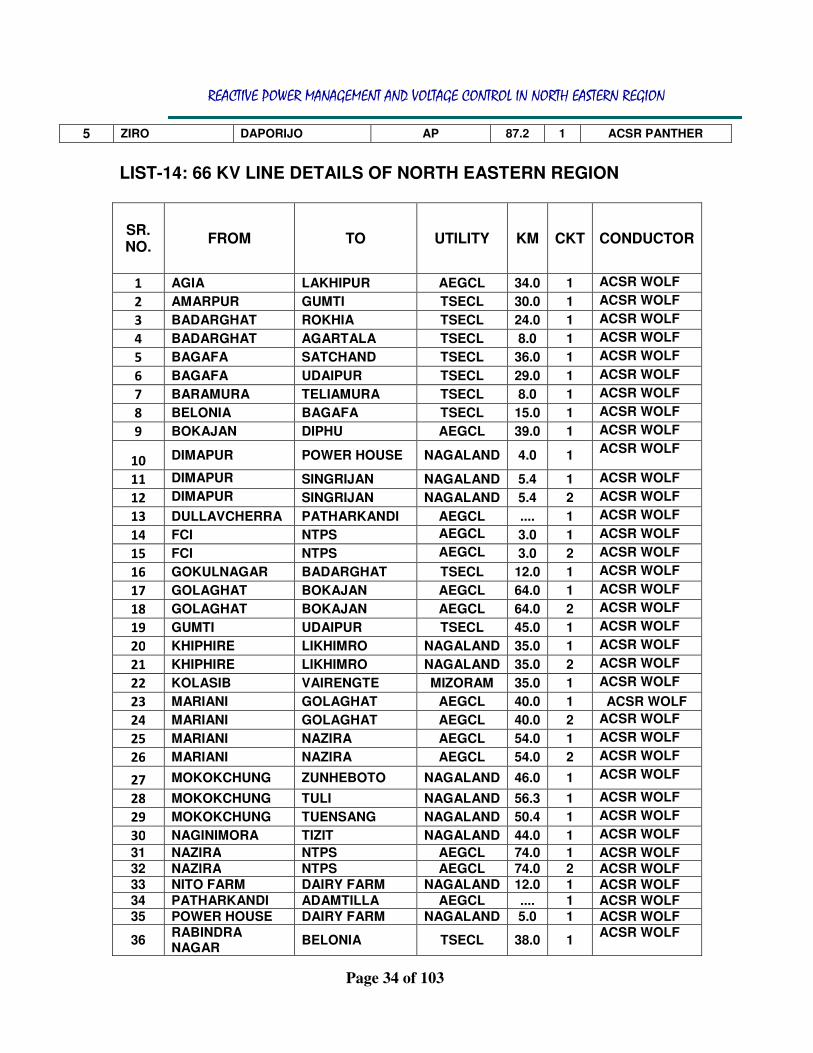
5 ZIRO DAPORIJO AP 87.2 1 ACSR PANTHER
LIST-14: 66 KV LINE DETAILS OF NORTH EASTERN REGION
SR. NO.
FROM TO UTILITY KM CKT CONDUCTOR
1 AGIA LAKHIPUR AEGCL 34.0 1 ACSR WOLF
2 AMARPUR GUMTI TSECL 30.0 1 ACSR WOLF
3 BADARGHAT ROKHIA TSECL 24.0 1 ACSR WOLF
4 BADARGHAT AGARTALA TSECL 8.0 1 ACSR WOLF
5 BAGAFA SATCHAND TSECL 36.0 1 ACSR WOLF
6 BAGAFA UDAIPUR TSECL 29.0 1 ACSR WOLF
7 BARAMURA TELIAMURA TSECL 8.0 1 ACSR WOLF
8 BELONIA BAGAFA TSECL 15.0 1 ACSR WOLF
9 BOKAJAN DIPHU AEGCL 39.0 1 ACSR WOLF
10 DIMAPUR POWER HOUSE NAGALAND 4.0 1
ACSR WOLF
11 DIMAPUR SINGRIJAN NAGALAND 5.4 1 ACSR WOLF
12 DIMAPUR SINGRIJAN NAGALAND 5.4 2 ACSR WOLF
13 DULLAVCHERRA PATHARKANDI AEGCL .... 1 ACSR WOLF
14 FCI NTPS AEGCL 3.0 1 ACSR WOLF
15 FCI NTPS AEGCL 3.0 2 ACSR WOLF
16 GOKULNAGAR BADARGHAT TSECL 12.0 1 ACSR WOLF
17 GOLAGHAT BOKAJAN AEGCL 64.0 1 ACSR WOLF
18 GOLAGHAT BOKAJAN AEGCL 64.0 2 ACSR WOLF
19 GUMTI UDAIPUR TSECL 45.0 1 ACSR WOLF
20 KHIPHIRE LIKHIMRO NAGALAND 35.0 1 ACSR WOLF
21 KHIPHIRE LIKHIMRO NAGALAND 35.0 2 ACSR WOLF
22 KOLASIB VAIRENGTE MIZORAM 35.0 1 ACSR WOLF
23 MARIANI GOLAGHAT AEGCL 40.0 1 ACSR WOLF
24 MARIANI GOLAGHAT AEGCL 40.0 2 ACSR WOLF
25 MARIANI NAZIRA AEGCL 54.0 1 ACSR WOLF
26 MARIANI NAZIRA AEGCL 54.0 2 ACSR WOLF
27 MOKOKCHUNG ZUNHEBOTO NAGALAND 46.0 1 ACSR WOLF
28 MOKOKCHUNG TULI NAGALAND 56.3 1 ACSR WOLF
29 MOKOKCHUNG TUENSANG NAGALAND 50.4 1 ACSR WOLF
30 NAGINIMORA TIZIT NAGALAND 44.0 1 ACSR WOLF
31 NAZIRA NTPS AEGCL 74.0 1 ACSR WOLF 32 NAZIRA NTPS AEGCL 74.0 2 ACSR WOLF 33 NITO FARM DAIRY FARM NAGALAND 12.0 1 ACSR WOLF 34 PATHARKANDI ADAMTILLA AEGCL .... 1 ACSR WOLF 35 POWER HOUSE DAIRY FARM NAGALAND 5.0 1 ACSR WOLF
36 RABINDRA NAGAR
BELONIA TSECL 38.0 1 ACSR WOLF

REACTIVE POWER MANAGEMENT AND VOLTAGE CONTROL IN NORTH EASTERN REGION
Page 35 of 103
37 ROKHIA RABINDRA NAGAR
TSECL 23.0 1 ACSR WOLF
38 SATCHAND SABROOM TSECL 15.0 1 ACSR WOLF
39 SINGRIJAN GANESH NAGAR
NAGALAND 21.4 1 ACSR WOLF
40 SINGRIJAN CHUMUKIDIMA NAGALAND 7.9 1 ACSR WOLF 41 TELIAMURA AMARPUR TSECL 35.0 1 ACSR WOLF 42 TINSUKIA RUPAI AEGCL 25.0 1 ACSR WOLF 43 TINSUKIA NTPS AEGCL 36.0 1 ACSR WOLF 44 TINSUKIA NTPS AEGCL 36.0 2 ACSR WOLF 45 TIZIT MON NAGALAND 31.0 1 ACSR WOLF 46 TUENSANG KHIPHIRE NAGALAND 55.7 1 ACSR WOLF 47 TULI NAGINIMORA NAGALAND 33.0 1 ACSR WOLF 48 UDAIPUR GOKULNAGAR TSECL 31.0 1 ACSR WOLF
LIST-15: SHUNT COMPENSATED LINES IN NORTH EASTERN REGION
SR. NO.
FROM TO UTILITY KM CKT SENDING END LINE REACTOR
RECEIVING END LINE REACTOR
1 BONGAIGAON BALIPARA POWERGRID 289.9 1 50 63
2 BONGAIGAON BALIPARA POWERGRID 289.9 2 50 63
3 BONGAIGAON BALIPARA POWERGRID 305 3 63 63
4 BONGAIGAON BALIPARA POWERGRID 305 4 63 63
5 MISA NEW MARIANI POWERGRID 382.9 1 50 NIL
6 MISA MARIANI POWERGRID 220 1 50 NIL
7 PALLATANA SILCHAR NETCL 247 1 63 50
8 PALLATANA SILCHAR NETCL 247 2 63 50
9 RANGANADI BALIPARA POWERGRID 166.3 1 50 50
10 RANGANADI BALIPARA POWERGRID 166.3 2 50 50
11 SILCHAR AZARA NETCL 264 1 63 63
12 SILCHAR BYRNIHAT NETCL 217.1 1 63 63
LIST-16: SHUNT COMPENSATED INTER – REGIONAL LINES IN NORTH EASTERN REGION
SR. NO.
FROM TO UTILITY KM CKT SENDING END LINE REACTOR
RECEIVING END LINE REACTOR
1 BONGAIGAON BINAGURI
(ER) POWERGRID 218 1 63 NIL
2 BONGAIGAON BINAGURI
(ER) POWERGRID 218 2 63 NIL

REACTIVE POWER MANAGEMENT AND VOLTAGE CONTROL IN NORTH EASTERN REGION
Page 36 of 103
LIST-17: INTER-STATE LINE DETAILS OF NORTH EASTERN REGION SR. NO.
CONNECTING STATES
OWNED BY FROM TO KV KM CKTS CONDUCTOR
1 ARUNACHAL – ASSAM
POWERGRID RANGANADI BALIPARA 400 166.3 D/C ACSR TWIN
MOOSE ARUNACHAL PRADESH DEOMALI KATHALGURI 220 19.0 S/C ACSR ZEBRA NEEPCO KHUPI BALIPARA 132 67.2 S/C ACSR PANTHER POWERGRID NIRJULI GOHPUR 132 42.5 S/C ACSR PANTHER
2 ASSAM – MEGHALAYA
POWERGRID BADARPUR KHLIEHRIET 132 76.6 S/C ACSR PANTHER POWERGRID KHANDONG KHLIEHRIET 132 42.5 D/C ACSR PANTHER AEGCL & MeECL PANCHGRAM LUMSHNONG 132 23.4 S/C ACSR PANTHER AEGCL & MeECL SARASUJAI UMTRU 132 37.0 D/C ACSR PANTHER AEGCL & MeECL AGIA NANGALBIBRA 132 S/C ACSR PANTHER AEGCL & MeECL KAHILIPARA UMTRU 132 9.0 D/C ACSR PANTHER
3
ASSAM - NAGALAND
POWERGRID MISA DIMAPUR 220 123.5 D/C ACSR ZEBRA AEGCL & NAGALAND MARIANI MOKOKCHUNG 132 50.0 S/C ACSR PANTHER AEGCL BOKAJAN DIMAPUR 132 5.0 S/C ACSR PANTHER AEGCL & NAGALAND BOKAJAN DIMAPUR 66 8.0 S/C ACSR WOLF
ASSAM – TRIPURA
AEGCL & TRIPURA DULLAVCHERRA DHARMANAGAR 132 29.0 S/C ACSR PANTHER
POWERGRID BADARPUR KUMARAGHAT 132 118.5 S/C ACSR PANTHER
4 ASSAM – MANIPUR
POWERGRID BADARPUR JIRIBAM 132 67.2 S/C ACSR PANTHER POWERGRID HAFLONG JIRIBAM 132 100.6 S/C ACSR PANTHER AEGCL PAILAPOOL JIRIBAM 132 15.0 S/C ACSR PANTHER
5 ASSAM – MIZORAM
POWERGRID BADARPUR KOLASIB 132 107.2 S/C ACSR PANTHER
6 MIZORAM – MANIPUR
POWERGRID AIZWAL JIRIBAM 132 172.3 S/C ACSR PANTHER
7 MIZORAM – TRIPURA
POWERGRID AIZWAL KUMARAGHAT 132 131.0 S/C ACSR PANTHER
8 NAGALAND – MANIPUR
POWERGRID DIMAPUR IMPHAL 132 168.9 S/C ACSR PANTHER MANIPUR & NAGALAND KOHIMA KARONG 132 50.0 S/C ACSR PANTHER

REACTIVE POWER MANAGEMENT AND VOLTAGE CONTROL IN NORTH EASTERN REGION
Page 37 of 103
LIST-18: FIXED, SWITCHABLE AND CONVERTIBLE LINE REACTORS IN NORTH EASTERN REGION.
SR. NO.
UTILITY FROM TO INSTALLED
AT (STATION) KV MVAR KM
CONVERTIBLE FIXED
1 POWERGRID BALIPARA MISA MISA 400 50 95.4 …. TRUE
2 POWERGRID BONGAIGAON BALIPARA BONGAIGAON 400 50 289.9 .... TRUE
3 POWERGRID BONGAIGAON BALIPARA BONGAIGAON 400 50 289.9 .... TRUE
4 POWERGRID BONGAIGAON BALIPARA BALIPARA 400 63 289.9 .... TRUE
5 POWERGRID BONGAIGAON BALIPARA BALIPARA 400 63 289.9 .... TRUE
6 POWERGRID BONGAIGAON BALIPARA BONGAIGAON 400 63 305.0 TRUE ….
7 POWERGRID BONGAIGAON BALIPARA BONGAIGAON 400 63 305.0 TRUE ….
8 POWERGRID BONGAIGAON BALIPARA BALIPARA 400 63 305.0 TRUE ….
9 POWERGRID BONGAIGAON BALIPARA BALIPARA 400 63 305.0 TRUE ….
10 POWERGRID BONGAIGAON BINAGURI(ER) BONGAIGAON 400 63 218.0 .... TRUE
11 POWERGRID BONGAIGAON BINAGURI(ER) BONGAIGAON 400 63 218.0 .... TRUE
12 POWERGRID MISA KATHALGURI MISA 220 50 382.9 .... TRUE
13 POWERGRID MISA MARIANI MISA 220 50 220.0 …. TRUE
14 POWERGRID PALATANA SILCHAR SILCHAR 400 50 247 TRUE ….
15 POWERGRID PALATANA SILCHAR SILCHAR 400 50 247 TRUE ….
16 POWERGRID PALATANA SILCHAR PALLATANA 400 63 247 …. ….
17 POWERGRID PALATANA SILCHAR PALLATANA 400 63 247 …. ….
18 POWERGRID RANGANADI BALIPARA RANGANADI 400 50 166.3 …. TRUE
19 POWERGRID RANGANADI BALIPARA RANGANADI 400 50 166.3 …. TRUE
20 POWERGRID RANGANADI BALIPARA BALIPARA 400 50 166.3 TRUE ....
21 POWERGRID RANGANADI BALIPARA BALIPARA 400 50 166.3 TRUE ....
22 POWERGRID SILCHAR BYRNIHAT SILCHAR 400 63 217.14 TRUE ….
23 POWERGRID SILCHAR BONGAIGAON SILCHAR 400 63 N/A TRUE ….

REACTIVE POWER MANAGEMENT AND VOLTAGE CONTROL IN NORTH EASTERN REGION
Page 38 of 103
24 POWERGRID SILCHAR AZARA SILCHAR 400 63 264 TRUE ….
25 AEGCL SILCHAR AZARA AZARA 400 63 264
NOTE: CONVERTIBLE: LINE REACTORS WHICH CAN BE OPERATED UPON ONLY WHEN LINE IS IN OUT CONDITION.
FIXED : LINE REACTORS WHICH ARE FIXED AND CANNOT BE OPERATED UPON AS A BUS REACTOR

REACTIVE POWER MANAGEMENT AND VOLTAGE CONTROL IN NORTH EASTERN REGION
Page 39 of 103
LIST-19: BUS REACTORS IN NORTH EASTERN REGION
SR. NO. UTILITY INSTALLED AT
(STATION) KV
RATING STATUS
MVAR MAKE 1 POWERGRID BALIPARA 400 50 BHEL IN SERVICE 2 POWERGRID BALIPARA 400 80 BHEL IN SERVICE 3 POWERGRID BONGAIGAON 400 2 X 50 BHEL IN SERVICE 4 POWERGRID BONGAIGAON 400 2 X 80 BHEL IN SERVICE 5 POWERGRID MISA 400 50 BHEL IN SERVICE 6 POWERGRID SILCHAR 400 2 X 63 CGL IN SERVICE 7 OTPC PALATANA 400 80 BHEL IN SERVICE 8 NEEPCO RANGANADI 400 50 …. IN SERVICE 9 ASSAM MARIANI 220 2 X 12.5 .... IN SERVICE 10 ASSAM SAMAGURI 220 2 X 12.5 .... IN SERVICE 11 POWERGRID AIZWAL 132 20 .... IN SERVICE 12 POWERGRID KUMARGHAT 132 20 .... IN SERVICE 13 TRIPURA DHARMANAGAR 132 2 X 2 .... IN SERVICE 14 POWERGRID ZIRO 132 20 …. IN SERVICE 15 POWERGRID IMPHAL 132 20 …. IN SERVICE 16 POWERGRID NEW MARIANI 132 20 …. IN SERVICE 17 ASSAM SAMAGURI 132 2X12.5 …. IN SERVICE 18 ASSAM AZARA 400 63 …. IN SERVICE 19 MEGHALAYA BYRNIHAT 400 63 IN SERVICE
LIST-20: TERTIARY REACTORS ON 33 KV SIDE OF 400/220/33 KV ICTS IN NORTH EASTERN REGION
SR. NO. UTILITY INSTALLED
AT (STATION) INSTALLED
ON RATING
STATUS MVAR MAKE
1 POWERGRID BALIPARA 33 KV SIDE OF
ICT I 4 X 25 BHEL IN SERVICE
2 POWERGRID BONGAIGAON 33 KV SIDE OF
ICT I 2 X 25 BHEL IN SERVICE
3 POWERGRID MISA 33 KV SIDE OF
ICT I 4 X 25 BHEL IN SERVICE

REACTIVE POWER MANAGEMENT AND VOLTAGE CONTROL IN NORTH EASTERN REGION
Page 40 of 103
3 SERIES AND SHUNT CAPACITOR VOLTAGE
CONTROL
3.1 INTRODUCTION
3.1.1 Capacitors aid in minimizing operating expenses and allow the utilities to serve new loads and consumers with a minimum system investment. Series and shunt capacitors in a power system generate reactive power to improve power factor and voltage, thereby enhancing the system capacity and reducing the losses.
3.1.2 In series capacitors the reactive power is proportional to the square of the load current, thus generating reactive power when it is most needed whereas in shunt capacitors it is proportional to the square of the voltage. Series capacitors compensation is usually applied for long transmission lines and transient stability improvement. Series compensation reduces net transmission line inductive reactance. The reactive generation I2XC compensates for the reactive consumption I2X of the transmission line. This is a self-regulating nature of series capacitors. At light loads series capacitors have little effect.
3.1.3 There are certain unfavorable aspects of series capacitors. Generally the cost of installing series capacitors is higher than that of a corresponding installation of a shunt capacitor.
3.1.4 This is because the protective equipment for a series capacitor is often more complicated. The factors which influence the choice between the shunt and series capacitors are summarized in Table 3.
Table 4. Equipment preference

REACTIVE POWER MANAGEMENT AND VOLTAGE CONTROL IN NORTH EASTERN REGION
Page 41 of 103
3.1.5 Due to various limitations in the use of series capacitors, shunt
capacitors are widely used in distribution systems. For the same voltage improvement, the rating of a shunt capacitor will be higher than that of a series capacitor. Thus a series capacitor stiffens the system, which is especially beneficial for starting large motors from an otherwise weak power system, for reducing light flicker caused by large fluctuating load, etc.
3.2 MeSEB CAPACITY BUILDING AND TRAINING DOCUMENT SUGGEST (Sub title as given in the PFC document for corporatization of MeSEB):
3.2.1 Installation of Shunt-capacitors:
Installation of capacitors is a low cost process for reduction of technical losses. The agricultural load mainly consists of irrigation pump motors. The PF of pump motors are generally below 0.6, which means the total reactive power demand of the system is high. The reactive power demand can be reduced by installation of suitable capacitors. However, proper maintenance has to be adopted to keep the system in order. In view of the maintenance problem, reactive compensation technique could be installed at the distribution transformer centers. Care has to be taken that it does not lead to over voltage problems during the off peak hours. To avoid this there should be switch off arrangement in the capacitor bank. The optimum allocation of LT capacitors at distribution substation by minimizing a cost function, which includes loss cost in the beneficiary system and the annual cost of the capacitor bank. The reactive compensation can also be carried out at the primary distribution feeders (11 KV) lines. The optimum number, size and location of online capacitors will depend on the following factors:
• Type of load.
• Quantum of load. • Load factor.
• Annual load cycle. • Power factor.
3.3 AS PER THE ASSAM GAZETTE, EXTRAORDINARY, FEBRUARY 10, 2005
IN CHAPTER 9: FREQUENCY AND VOLTAGE MANAGEMENT Sec 9.1 (d) System voltages levels can be affected by Regional operation.
The SLDC shall optimize voltage management by adjusting transformer taps to the extent available and switching of

REACTIVE POWER MANAGEMENT AND VOLTAGE CONTROL IN NORTH EASTERN REGION
Page 42 of 103
circuits/ capacitors/ reactors and other operational steps. SLDC will instruct generating stations to regulate MVAr generation within their declared parameters. SLDC shal also instruct Distribution Licensees to regulate demand, if necessary.
LIST-21: SUBSTATIONS IN NER
AGENCY 400KV 220 KV 132 KV &
66 KV TOTAL
POWER GRID 4 3 11 18
ARUNACHAL PRADESH
NIL 1 6 7
AEGCL 1 8 22 31
MANIPUR NIL NIL 7 7
MeECL 1 NIL 9 10
MIZORAM NIL NIL 6 6
NAGALAND NIL NIL 7 7
NEEPCO 1 2 4 7
NHPC NIL NIL 1 1
TSECL 1 NIL 9 10
OTPC 1 NIL NIL 1
TOTAL 9 14 82 105
REACTIVE POWER MANAGEMENT AND VOLTAGE CONTROL IN NORTH EASTERN REGION
Page 43 of 103
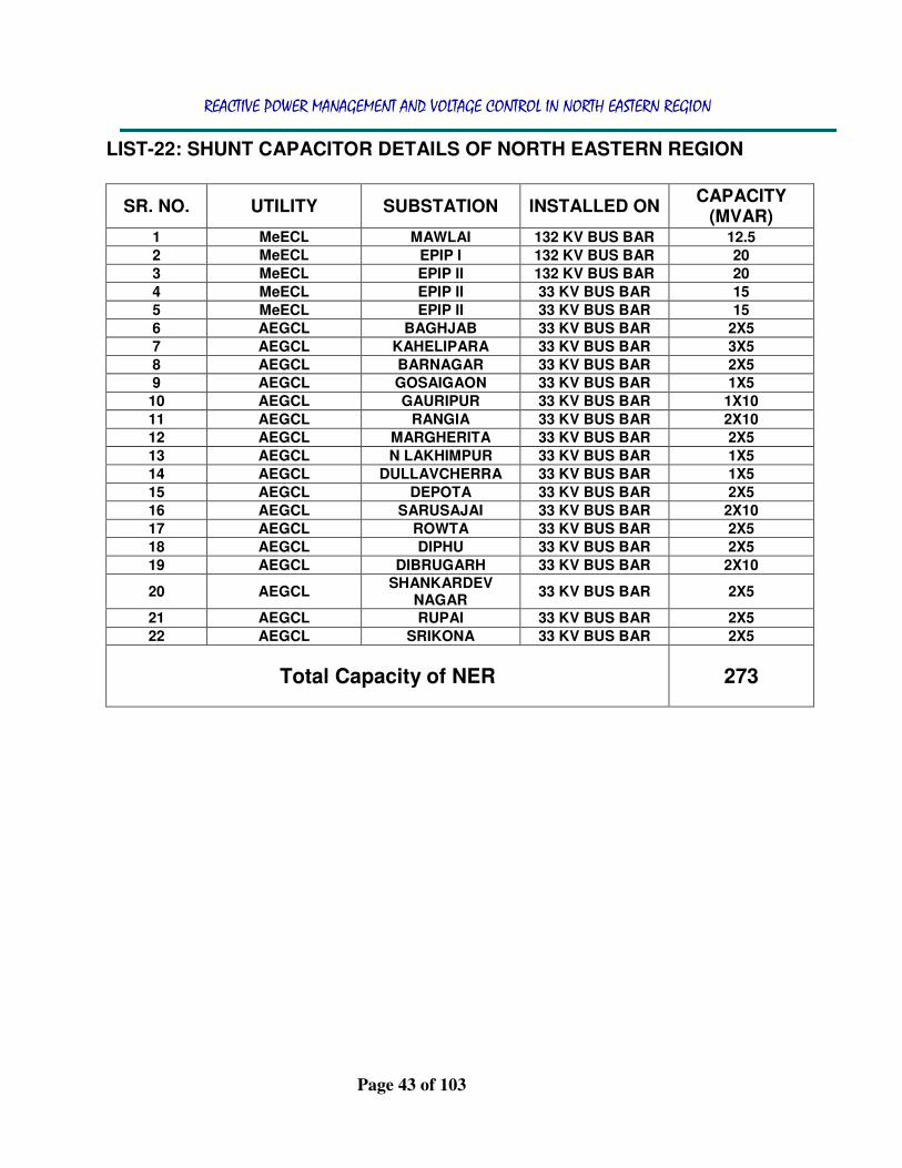
LIST-22: SHUNT CAPACITOR DETAILS OF NORTH EASTERN REGION
SR. NO. UTILITY SUBSTATION INSTALLED ON CAPACITY
(MVAR) 1 MeECL MAWLAI 132 KV BUS BAR 12.5
2 MeECL EPIP I 132 KV BUS BAR 20
3 MeECL EPIP II 132 KV BUS BAR 20
4 MeECL EPIP II 33 KV BUS BAR 15
5 MeECL EPIP II 33 KV BUS BAR 15
6 AEGCL BAGHJAB 33 KV BUS BAR 2X5
7 AEGCL KAHELIPARA 33 KV BUS BAR 3X5
8 AEGCL BARNAGAR 33 KV BUS BAR 2X5
9 AEGCL GOSAIGAON 33 KV BUS BAR 1X5
10 AEGCL GAURIPUR 33 KV BUS BAR 1X10
11 AEGCL RANGIA 33 KV BUS BAR 2X10
12 AEGCL MARGHERITA 33 KV BUS BAR 2X5
13 AEGCL N LAKHIMPUR 33 KV BUS BAR 1X5
14 AEGCL DULLAVCHERRA 33 KV BUS BAR 1X5
15 AEGCL DEPOTA 33 KV BUS BAR 2X5
16 AEGCL SARUSAJAI 33 KV BUS BAR 2X10
17 AEGCL ROWTA 33 KV BUS BAR 2X5
18 AEGCL DIPHU 33 KV BUS BAR 2X5
19 AEGCL DIBRUGARH 33 KV BUS BAR 2X10
20 AEGCL SHANKARDEV
NAGAR 33 KV BUS BAR 2X5
21 AEGCL RUPAI 33 KV BUS BAR 2X5
22 AEGCL SRIKONA 33 KV BUS BAR 2X5
Total Capacity of NER
273

REACTIVE POWER MANAGEMENT AND VOLTAGE CONTROL IN NORTH EASTERN REGION
Page 44 of 103
4 TRANSFORMER LOAD TAP CHANGER AND
VOLTAGE CONTROL
4.1 INTRODUCTION
4.1.1 Transformers provide the capability to raise alternating-current generation voltages to levels that make long-distance power transfers practical and then lowering voltages back to levels that can be distributed and used. The ratio of the number of turns in the primary to the number of turns in the secondary coil determines the ratio of the primary voltage to the secondary voltage. By tapping the primary or secondary coil at various points, the ratio between the primary and secondary voltage can be adjusted. Transformer taps can be either fixed or adjustable under load through the use of a load-tap changer (LTC). Tap capability is selected for each application during transformer design.
4.1.2 The OLTC alters the power transformer turns ratio in a number of pre defined steps and in that way changes the secondary side voltage.
4.1.3 Each step usually represents a change in LV side no-load voltage of approximately 0.5-1.7%. Standard tap changers offer between ± 9 to ± 17 steps (i.e. 19 to 35 positions). The automatic voltage regulator (AVR) is designed to control a power transformer with a motor driven on-load tap-changer.
4.1.4 Typically the AVR regulates voltage at the secondary side of the power transformer. The control method is based on a step-by-step principle which means that a control pulse, one at a time, will be issued to the on-load tap-changer mechanism to move it up or down by one position.
4.1.5 The pulse is generated by the AVR whenever the measured voltage, for a given time, deviates from the set reference value by more than the preset dead band (i.e. degree of insensitivity). Time delay is used to avoid
Fig 13. Switching principle of LTC

REACTIVE POWER MANAGEMENT AND VOLTAGE CONTROL IN NORTH EASTERN REGION
Page 45 of 103
unnecessary operation during short voltage deviations from the pre-set value.
4.1.6 Transformer-tap changers can be used for voltage control, but the control differs from that provided by reactive sources. Transformer taps can force voltage up (or down) on one side of a transformer, but it is at the expense of reducing (or raising) the voltage on the other side. The reactive power required to raise (or lower) voltage on a bus is forced to flow through the transformer from the bus on the other side.
4.1.7 The reactive power consumption of a transformer at rated current is within the range 0.05 to 0.2 p.u. based on the transformer ratings. Fixed taps are useful when compensating for load growth and other long-term shifts in system use. LTCs are used for more-rapid adjustments, such as compensating for the voltage fluctuations associated with the daily load cycle. While LTCs could potentially provide rapid voltage control, their performance is normally intentionally degraded. With an LTC, tap changing is accomplished by opening and closing contacts within the transformer’s tap changing mechanism.
4.2 AS PER THE ASSAM GAZETTE, EXTRAORDINARY, FEBRUARY 10, 2005 IN CHAPTER 9: FREQUENCY AND VOLTAGE MANAGEMENT Sec 9.1(d) System voltages levels can be affected by Regional operation. The SLDC shall optimise voltage management by adjusting transformer taps to the extent available and switching of circuits/ capacitors/ reactors and other operational steps. SLDC will instruct generating stations to regulate MVAr generation within their declared parameters. SLDC shall also instruct Distribution Licensees to regulate demand, if necessary.
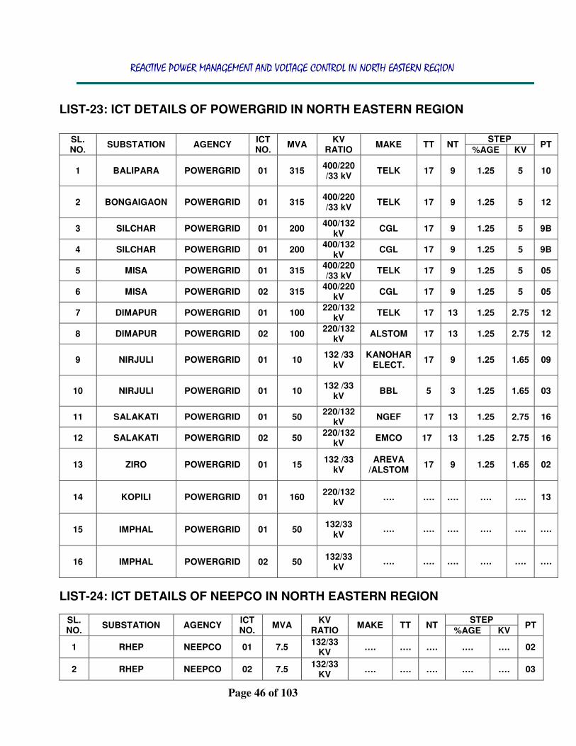
REACTIVE POWER MANAGEMENT AND VOLTAGE CONTROL IN NORTH EASTERN REGION
Page 46 of 103
LIST-23: ICT DETAILS OF POWERGRID IN NORTH EASTERN REGION
LIST-24: ICT DETAILS OF NEEPCO IN NORTH EASTERN REGION
SL. NO.
SUBSTATION AGENCY ICT NO.
MVA KV
RATIO MAKE TT NT
STEP PT
%AGE KV
1 RHEP NEEPCO 01 7.5 132/33
KV …. …. …. …. …. 02
2 RHEP NEEPCO 02 7.5 132/33
KV …. …. …. …. …. 03
SL. NO.
SUBSTATION AGENCY ICT NO.
MVA KV
RATIO MAKE TT NT
STEP PT
%AGE KV
1 BALIPARA POWERGRID 01 315 400/220 /33 kV
TELK 17 9 1.25 5 10
2 BONGAIGAON POWERGRID 01 315 400/220 /33 kV
TELK 17 9 1.25 5 12
3 SILCHAR POWERGRID 01 200 400/132
kV CGL 17 9 1.25 5 9B
4 SILCHAR POWERGRID 01 200 400/132
kV CGL 17 9 1.25 5 9B
5 MISA POWERGRID 01 315 400/220 /33 kV
TELK 17 9 1.25 5 05
6 MISA POWERGRID 02 315 400/220
kV CGL 17 9 1.25 5 05
7 DIMAPUR POWERGRID 01 100 220/132
kV TELK 17 13 1.25 2.75 12
8 DIMAPUR POWERGRID 02 100 220/132
kV ALSTOM 17 13 1.25 2.75 12
9 NIRJULI POWERGRID 01 10 132 /33
kV KANOHAR
ELECT. 17 9 1.25 1.65 09
10 NIRJULI POWERGRID 01 10 132 /33
kV BBL 5 3 1.25 1.65 03
11 SALAKATI POWERGRID 01 50 220/132
kV NGEF 17 13 1.25 2.75 16
12 SALAKATI POWERGRID 02 50 220/132
kV EMCO 17 13 1.25 2.75 16
13 ZIRO POWERGRID 01 15 132 /33
kV AREVA
/ALSTOM 17 9 1.25 1.65 02
14 KOPILI POWERGRID 01 160 220/132
kV …. …. …. …. …. 13
15 IMPHAL POWERGRID 01 50 132/33
kV
….
….
….
….
….
….
16 IMPHAL POWERGRID 02 50 132/33
kV
….
….
….
….
….
….

REACTIVE POWER MANAGEMENT AND VOLTAGE CONTROL IN NORTH EASTERN REGION
Page 47 of 103
3 BALIPARA NEEPCO 01 50 220/132
KV …. …. …. …. …. 09
4 KOPILI NEEPCO 01 60 220/132
KV …. …. …. …. …. 09
5 RHEP NEEPCO 01 360 400/132
KV …. …. …. …. …. 10
6 RHEP NEEPCO 02 360 400/132
KV …. …. …. …. …. 09
LIST-25: ICT DETAILS OF NHPC IN NORTH EASTERN REGION
SL. NO.
SUBSTATION AGENCY ICT NO.
MVA KV
RATIO MAKE TT NT
STEP PT
%AGE KV
1 LOKTAK NHPC 01 5 132/33
KV …. …. …. …. …. 02
LIST-26: ICT DETAILS OF ARUNACHAL PRADESH IN NORTH EASTERN REGION
LIST-27: ICT DETAILS OF AEGCL IN NORTH EASTERN REGION
SL. NO.
SUBSTATION AGENCY ICT NO.
MVA kV
RATIO MAKE TT NT
STEP PT
%AGE KV
1 AGIA AEGCL 01 50 220/132
kV …. …. …. …. …. 14
2 AGIA AEGCL 02 100 220/132
kV
…. …. …. …. …. ….
2 AGIA AEGCL 01 40 132/33
kV …. …. …. …. …. 05
3 AGIA AEGCL 01 12.5 132/33
kV …. …. …. …. …. 05
SL. NO.
SUBSTATION AGENCY ICT NO.
MVA KV
RATIO MAKE TT NT
STEP PT
%AGE KV
1 ALONG ARUNACHAL
PRADESH 01 15
132/33 KV
…. …. …. …. …. 03
2 DAPORIJO ARUNACHAL
PRADESH 01 5
132/33 KV
…. …. …. …. …. 02
3 DAPORIJO ARUNACHAL
PRADESH 02 5
132/33 KV
…. …. …. …. …. 02
4 DEOMALI ARUNACHAL
PRADESH 01 100
220/ 132 kV
…. …. …. …. …. 09
5 DEOMALI ARUNACHAL
PRADESH 01 16
132/33 KV
…. …. …. …. …. 04
6 LEKHI ARUNACHAL
PRADESH 01 15
132/33 KV
…. …. …. …. …. 05
7 LEKHI ARUNACHAL
PRADESH 01 20
132/33 KV
…. …. …. …. …. 05

REACTIVE POWER MANAGEMENT AND VOLTAGE CONTROL IN NORTH EASTERN REGION
Page 48 of 103
4 AZARA AEGCL 01 315 400/220 EMCO …. …. …. ….
08
5 AZARA AEGCL 02 315 400/220 EMCO …. …. …. ….
08
6 ASHOK PAPER MILL
AEGCL 01 12.5 132/33
kV …. …. …. …. …. 05
7 ASHOK PAPER MILL
AEGCL 01 16 132/33
kV …. …. …. …. …. 05
8 BAGHJHAP AEGCL 01 16 132/33
kV …. …. …. …. …. 05
9 BAGHJHAP AEGCL 02 16 132/33
kV …. …. …. …. …. 05
10 BALIPARA AEGCL 01 50 220 /132
kV …. …. …. …. …. 09
11 BOKO AEGCL 01 10 220/132
kV …. …. …. …. …. 05
12 BOKO AEGCL 02 10 220/132
kV …. …. …. …. …. 05
13 B CHARIALI AEGCL 01 16 132/33
kV …. …. …. …. …. 17
14 B CHARIALI AEGCL 02 16 132/33
kV …. …. …. …. …. 17
15 BORNAGAR AEGCL 01 25 132/33
kV …. …. …. …. …. ….
16 BORNAGAR AEGCL 02 25 132/33
kV …. …. …. …. …. ….
17 BOKAKHAT AEGCL 01 16 132/33
kV …. …. …. …. …. ….
18 BOKAKHAT AEGCL 02 16 132/33
kV …. …. …. …. …. ….
19 BOKAJAN AEGCL 01 16 132/33
kV …. …. …. …. …. ….
20 BTPS AEGCL 01 10 132/33
kV …. …. …. …. …. ….
21 BTPS AEGCL 02 10 132/33
kV …. …. …. …. …. ….
22 BTPS AEGCL 01 80 220/132
kV …. …. …. …. …. ….
23 BTPS AEGCL 02 80 220/132
kV …. …. …. …. …. ….
24 BTPS AEGCL 03 160 220/132
kV …. …. …. …. …. ….
25 CTPS AEGCL 01 16 132/33
kV …. …. …. …. …. ….
26 CTPS AEGCL 01 30 132/33
kV …. …. …. …. …. ….
27 DEPOTA AEGCL 01 31.5 132/33
kV …. …. …. …. …. 05
28 DEPOTA AEGCL 02 31.5 132/33
kV …. …. …. …. …. 05
29 DHALIGAON AEGCL 01 25 132/33
kV …. …. …. …. …. ….
30 DHALIGAON AEGCL 02 25 132/33
kV …. …. …. …. …. ….
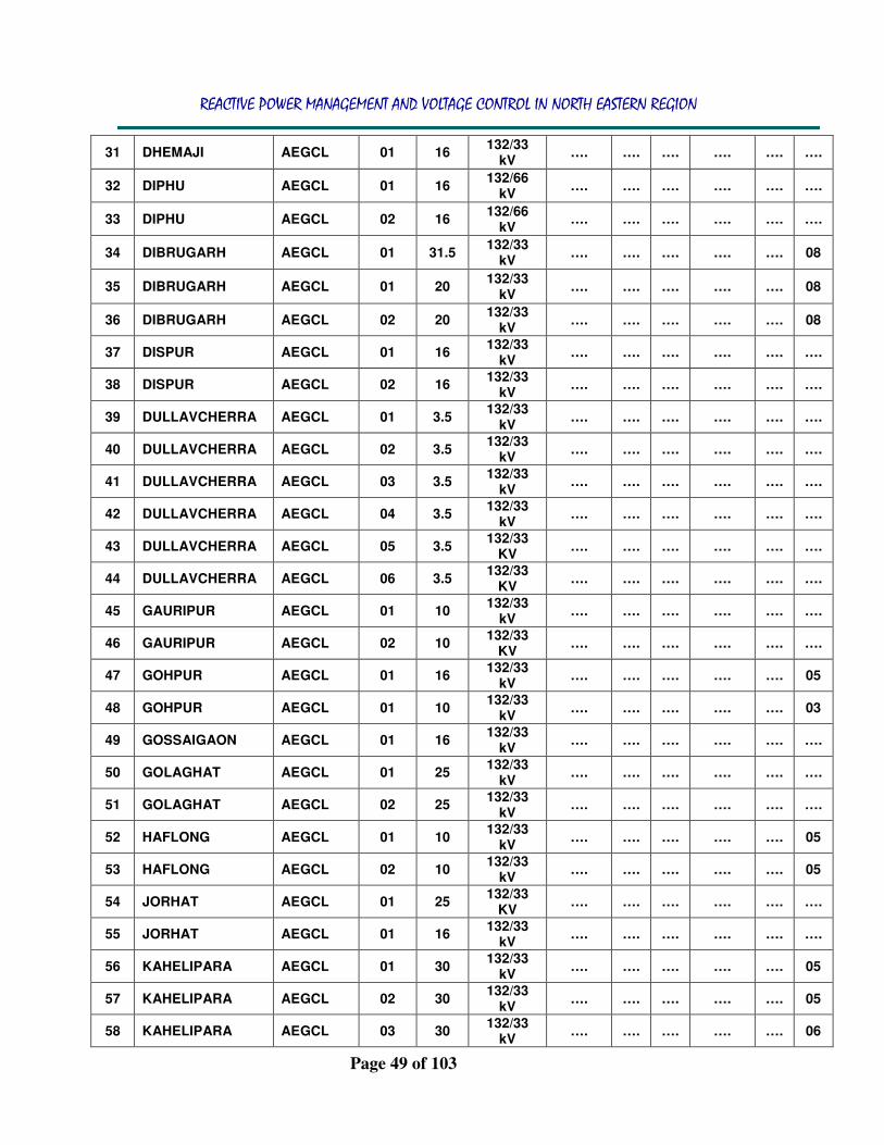
REACTIVE POWER MANAGEMENT AND VOLTAGE CONTROL IN NORTH EASTERN REGION
Page 49 of 103
31 DHEMAJI AEGCL 01 16 132/33
kV …. …. …. …. …. ….
32 DIPHU AEGCL 01 16 132/66
kV …. …. …. …. …. ….
33 DIPHU AEGCL 02 16 132/66
kV …. …. …. …. …. ….
34 DIBRUGARH AEGCL 01 31.5 132/33
kV …. …. …. …. …. 08
35 DIBRUGARH AEGCL 01 20 132/33
kV …. …. …. …. …. 08
36 DIBRUGARH AEGCL 02 20 132/33
kV …. …. …. …. …. 08
37 DISPUR AEGCL 01 16 132/33
kV …. …. …. …. …. ….
38 DISPUR AEGCL 02 16 132/33
kV …. …. …. …. …. ….
39 DULLAVCHERRA AEGCL 01 3.5 132/33
kV …. …. …. …. …. ….
40 DULLAVCHERRA AEGCL 02 3.5 132/33
kV …. …. …. …. …. ….
41 DULLAVCHERRA AEGCL 03 3.5 132/33
kV …. …. …. …. …. ….
42 DULLAVCHERRA AEGCL 04 3.5 132/33
kV …. …. …. …. …. ….
43 DULLAVCHERRA AEGCL 05 3.5 132/33
KV …. …. …. …. …. ….
44 DULLAVCHERRA AEGCL 06 3.5 132/33
KV …. …. …. …. …. ….
45 GAURIPUR AEGCL 01 10 132/33
kV …. …. …. …. …. ….
46 GAURIPUR AEGCL 02 10 132/33
KV …. …. …. …. …. ….
47 GOHPUR AEGCL 01 16 132/33
kV …. …. …. …. …. 05
48 GOHPUR AEGCL 01 10 132/33
kV …. …. …. …. …. 03
49 GOSSAIGAON AEGCL 01 16 132/33
kV …. …. …. …. …. ….
50 GOLAGHAT AEGCL 01 25 132/33
kV …. …. …. …. …. ….
51 GOLAGHAT AEGCL 02 25 132/33
kV …. …. …. …. …. ….
52 HAFLONG AEGCL 01 10 132/33
kV …. …. …. …. …. 05
53 HAFLONG AEGCL 02 10 132/33
kV …. …. …. …. …. 05
54 JORHAT AEGCL 01 25 132/33
KV …. …. …. …. …. ….
55 JORHAT AEGCL 01 16 132/33
kV …. …. …. …. …. ….
56 KAHELIPARA AEGCL 01 30 132/33
kV …. …. …. …. …. 05
57 KAHELIPARA AEGCL 02 30 132/33
kV …. …. …. …. …. 05
58 KAHELIPARA AEGCL 03 30 132/33
kV …. …. …. …. …. 06

REACTIVE POWER MANAGEMENT AND VOLTAGE CONTROL IN NORTH EASTERN REGION
Page 50 of 103
59 KAHELIPARA AEGCL 01 10 132/33/11
kV …. …. …. …. …. 02
60 KAHELIPARA AEGCL 02 10 132/33/11
kV …. …. …. …. …. 02
61 LEDO AEGCL 01 10 132/33
kV …. …. …. …. …. 06
62 LEDO AEGCL 02 10 132/33
kV …. …. …. …. …. 06
63 LTPS AEGCL 01 7.5 132/33
kV …. …. …. …. …. ….
64 LTPS AEGCL 02 7.5 132/33
kV …. …. …. …. …. ….
65 MAJULI AEGCL 01 5.5 132/33
kV …. …. …. …. …. ….
66 MARIANI AEGCL 01 20 132/66
kV …. …. …. …. …. 06
67 MARIANI AEGCL 02 20 132/66
kV …. …. …. …. …. 06
68 MARIANI AEGCL 01 100 220/132
kV …. …. …. …. …. 13
69 MARIANI AEGCL 02 100 220/132
kV …. …. …. …. …. 13
70 MORAN AEGCL 01 16 132/33
KV …. …. …. …. …. ….
71 MORAN AEGCL 02 16 132/33
kV …. …. …. …. …. ….
72 NALBARI AEGCL 01 16 132/33
kV …. …. …. …. …. ….
73 NALBARI AEGCL 02 16 132/33
kV …. …. …. …. …. ….
74 NALKATA (NORTH LAKHIMPUR)
AEGCL 01 10 132/33
kV …. …. …. …. …. ….
75 NALKATA (NORTH LAKHIMPUR)
AEGCL 02 10 132/33
kV …. …. …. …. …. ….
76 NARENGI AEGCL 01 25 132/33
kV …. …. …. …. …. ….
77 NARENGI AEGCL 02 25 132/33
kV …. …. …. …. …. ….
78 NAZIRA AEGCL 01 25 132/33
kV …. …. …. …. …. 06
79 NTPS AEGCL 01 25 132/66
kV …. …. …. …. …. ….
80 NTPS AEGCL 02 25 132/66
kV …. …. …. …. …. ….
81 PAILAPOOL AEGCL 01 10 132/33
kV …. …. …. …. …. 05
82 PAILAPOOL AEGCL 02 10 132/33
kV …. …. …. …. …. 05
83 PAILAPOOL AEGCL 03 10 132/33
kV …. …. …. …. …. 05
84 PANCHGRAM AEGCL 01 16 132/33
kV …. …. …. …. …. 08
85 PANCHGRAM AEGCL 02 16 132/33
kV …. …. …. …. …. 08

REACTIVE POWER MANAGEMENT AND VOLTAGE CONTROL IN NORTH EASTERN REGION
Page 51 of 103
86 PANCHGRAM AEGCL 01 10 132/33
kV …. …. …. …. …. 01
87 PANCHGRAM AEGCL 02 10 132/33
kV …. …. …. …. …. 03
88 PAVOI AEGCL 01 16 132/33
KV …. …. …. …. …. ….
89 PAVOI AEGCL 02 16 132/33
KV …. …. …. …. …. ….
90 RANGIA AEGCL 01 25 132/33
KV …. …. …. …. …. 03
91 RANGIA AEGCL 02 25 132/33
KV …. …. …. …. …. 03
92 ROWTA AEGCL 01 25 132/33
KV …. …. …. …. …. 03
93 ROWTA AEGCL 02 25 132/33
KV …. …. …. …. …. 03
94 S NAGAR AEGCL 01 16 132/33
KV …. …. …. …. …. 04
95 S NAGAR AEGCL 02 16 132/33
KV …. …. …. …. …. 05
96 SAMAGURI AEGCL 01 50 220/132
kV …. …. …. …. …. 12
97 SAMAGURI AEGCL 02 50 220/132
kV …. …. …. …. …. 12
98 SAMAGURI AEGCL 03 50 220/132
kV …. …. …. …. …. 12
99 SAMAGURI AEGCL 01 25 132/33
KV …. …. …. …. …. 06
100 SAMAGURI AEGCL 02 25 132/33
KV …. …. …. …. …. 06
101 SARUSAJAI AEGCL 01 31.5 132/33
KV …. …. …. …. …. 06
102 SARUSAJAI AEGCL 02 31.5 132/33
KV …. …. …. …. …. 06
103 SARUSAJAI AEGCL 01 100 220/132
KV …. …. …. …. …. 10
104 SARUSAJAI AEGCL 02 100 220/132
kV …. …. …. …. …. 12
105 SARUSAJAI AEGCL 03 100 220/132
kV …. …. …. …. …. 11
106 SISUGRAM AEGCL 01 31.5 132/33
KV …. …. …. …. …. 06
107 SISUGRAM AEGCL 02 31.5 132/33
KV …. …. …. …. …. 06
108 SIBSAGAR AEGCL 01 16 132/33
KV …. …. …. …. …. ….
109 SIBSAGAR AEGCL 02 16 132/33
KV …. …. …. …. …. ….
110 SIPAJHAR AEGCL 01 16 132/33
KV …. …. …. …. …. ….
111 SIPAJHAR AEGCL 02 16 132/33
KV …. …. …. …. …. ….
112 SRIKONA AEGCL 01 25 132/33
KV …. …. …. …. …. 05
113 SRIKONA AEGCL 02 25 132/33
KV …. …. …. …. …. 05

REACTIVE POWER MANAGEMENT AND VOLTAGE CONTROL IN NORTH EASTERN REGION
Page 52 of 103
114 TINSUKIA AEGCL 01 20 132/66
KV …. …. …. …. …. 02
115 TINSUKIA AEGCL 02 20 132/66
KV …. …. …. …. …. 04
116 TINSUKIA AEGCL 03 20 132/66
KV …. …. …. …. …. 03
117 TINSUKIA AEGCL 01 50 220/132
kV …. …. …. …. …. 16
118 TINSUKIA AEGCL 02 50 220/132
kV …. …. …. …. …. 16
LIST-28: ICT DETAILS OF MANIPUR IN NORTH EASTERN REGION
SL. NO.
SUBSTATION AGENCY ICT NO.
MVA KV
RATIO MAKE TT NT
STEP PT
%AGE KV
1 CHURACHANDPUR MANIPUR 01 20 132/33
KV …. …. …. …. …. ….
2 IMPHAL MANIPUR 01 20 132/33
KV …. …. …. …. …. ….
3 IMPHAL MANIPUR 02 20 132/33
KV …. …. …. …. …. ….
4 IMPHAL MANIPUR 03 20 132/33
KV …. …. …. …. …. ….
5 KAKCHING MANIPUR 01 20 132/33
KV …. …. …. …. …. ….
6 KARONG MANIPUR 01 20 132/33
KV …. …. …. …. …. ….
7 NINGTHOUKHONG MANIPUR 01 12.5 132/33
KV …. …. …. …. …. ….
8 NINGTHOUKHONG MANIPUR 02 12.5 132/33
KV …. …. …. …. …. ….
9 YANGANGPOKPI MANIPUR 01 20 132/33
KV …. …. …. …. …. ….
10 YANGANGPOKPI MANIPUR 02 20 132/33
KV …. …. …. …. …. ….
11 JIRIBAM MANIPUR 01 6.3 132/33
KV …. …. …. …. …. ….
LIST-29: ICT DETAILS OF MEGHALAYA IN NORTH EASTERN REGION
SL. NO.
SUBSTATION AGENCY ICT NO.
MVA KV
RATIO MAKE TT NT
STEP PT
%AGE KV
1 CHERAPUNJEE MeECL 01 12.5 132/33
KV …. …. …. …. …. 06
2 EPIP I MeECL 01 20 132/33
KV …. …. …. …. …. 03
3 EPIP I MeECL 02 20 132/33
KV …. …. …. …. …. 03
4 EPIP II MeECL 01 50 132/33
KV …. …. …. …. …. 08
5 KHLIEHRIAT MeECL 01 20 132/33
KV …. …. …. …. …. 05

REACTIVE POWER MANAGEMENT AND VOLTAGE CONTROL IN NORTH EASTERN REGION
Page 53 of 103
6 KHLIEHRIAT MeECL 02 20 132/33
KV …. …. …. …. …. 06
7 MAWLAI MeECL 01 20 132/33
KV …. …. …. …. …. 04
8 MAWLAI MeECL 02 20 132/33
KV …. …. …. …. …. 08
9 MAWLAI MeECL 01 10 132/33
KV …. …. …. …. …. 03
10 MAWLAI MeECL 01 12.5 132/33
KV …. …. …. …. …. 07
11 NANGALBIBRA MeECL 01 10 132/33
KV …. …. …. …. …. 07
12 NANGALBIBRA MeECL 01 12.5 132/33
KV …. …. …. …. …. 06
13 NEHU MeECL 01 20 132/33
KV …. …. …. …. …. 06
14 NEHU MeECL 02 20 132/33
KV …. …. …. …. …. 06
15 NEIGRIHMS MeECL 01 10 132/33
KV …. …. …. …. …. 05
16 NEIGRIHMS MeECL 02 10 132/33
KV …. …. …. …. …. 04
17 NONGSTOIN MeECL 01 12.5 132/33
KV …. …. …. …. …. 04
18 UMIUM ST III MeECL 01 10 132/33
KV …. …. …. …. …. 08
19 TURA MeECL 01 20 132/33
KV …. …. …. …. …. 15
20 TURA MeECL 01 15 132/33
KV …. …. …. …. …. 15
21 TURA MeECL 02 15 132/33
KV …. …. …. …. …. 15
22 TURA MeECL 03 15 132/33
KV …. …. …. …. …. 15
23 LUMSHNONG MeECL 01 10 132/33
KV …. …. …. …. …. ….
24 UMTRU MeECL 01 20 132/33
KV …. …. …. …. …. 02
25 BYRNIHAT MeECL 01 315 400/132
26 BYRNIHAT MeECL 02 315 400/132
27 NANGALBIBRA MeECL 01 12.5 132/33
28 NANGALBIBRA MeECL 02 12.5 132/33
LIST-30: ICT DETAILS OF MIZORAM IN NORTH EASTERN REGION
SL. NO.
SUBSTATION AGENCY ICT NO.
MVA KV
RATIO MAKE TT NT
STEP PT
%AGE KV
1 AIZAWL
LUANGMUAL MIZORAM 01 12.5
132/33 KV
…. …. …. …. …. 05
2 AIZAWL
LUANGMUAL MIZORAM 02 12.5
132/33 KV
…. …. …. …. …. 05

REACTIVE POWER MANAGEMENT AND VOLTAGE CONTROL IN NORTH EASTERN REGION
Page 54 of 103
3 AIZAWL
ZUANGTUI MIZORAM 01 12.5
132/33 KV
…. …. …. …. …. 05
4 AIZAWL
ZUANGTUI MIZORAM 02 12.5
132/33 KV
…. …. …. …. …. 05
5 KOLASIB MIZORAM 01 12.5 132/66
KV …. …. …. …. …. 10
6 KOLASIB MIZORAM 02 12.5 132/66
KV …. …. …. …. …. 09
7 LUNGLEI MIZORAM 01 12.5 132/33
KV …. …. …. …. …. 05
8 LUNGLEI MIZORAM 02 12.5 132/33
KV …. …. …. …. …. 09
9 SERCHHIP MIZORAM 01 12.5 132/33
KV …. …. …. …. …. 02
10 SERCHHIP MIZORAM 02 6.3 132/33
KV …. …. …. …. …. 03
11 SAITUAL MIZORAM 01 6.3 132/33
KV …. …. …. …. …. 06
LIST-31: ICT DETAILS OF NAGALAND IN NORTH EASTERN REGION
SL. NO.
SUBSTATION AGENCY ICT NO.
MVA KV
RATIO MAKE TT NT
STEP PT
%AGE KV
1 DIMAPUR NAGALAND 01 20 132/66
KV …. …. …. …. …. 05
2 DIMAPUR NAGALAND 02 20 132/66
KV …. …. …. …. …. 05
3 DIMAPUR NAGALAND 03 20 132/66
KV …. …. …. …. …. 03
4 KIPHIRE NAGALAND 01 6.5 132/66
KV …. …. …. …. …. 04
5 KIPHIRE NAGALAND 02 6.5 132/66
KV …. …. …. …. …. 04
6 KIPHIRE NAGALAND 03 6.5 132/66
KV …. …. …. …. …. 04
7 KOHIMA NAGALAND 01 8 132/33
KV …. …. …. …. …. 03
8 KOHIMA NAGALAND 02 8 132/33
KV …. …. …. …. …. 03
9 KOHIMA NAGALAND 03 8 132/33
KV …. …. …. …. …. 03
10 MELURI NAGALAND 01 5 132/33
KV …. …. …. …. …. 01
11 MOKOKCHUNG NAGALAND 01 12.5 132/66
KV …. …. …. …. …. 04
12 MOKOKCHUNG NAGALAND 02 12.5 132/66
KV …. …. …. …. …. 04
13 WOKHA NAGALAND 01 5 132/33
KV …. …. …. …. …. 03

REACTIVE POWER MANAGEMENT AND VOLTAGE CONTROL IN NORTH EASTERN REGION
Page 55 of 103
LIST-32: ICT DETAILS OF TSECL IN NORTH EASTERN REGION
SL. NO.
SUBSTATION AGENCY ICT NO.
MVA KV
RATIO MAKE TT NT
STEP PT
%AGE KV
1 AGARTALA TSECL 01 15 132/66
KV …. …. …. …. …. 09
2 AGARTALA TSECL 01 15 132/33
KV …. …. …. …. …. 13
3 AGARTALA TSECL 02 15 132/33
KV …. …. …. …. …. 13
4 AGARTALA TSECL 03 15 132/33
KV …. …. …. …. …. 13
5 AGARTALA TSECL 04 15 132/33
KV …. …. …. …. …. 13
6 AGARTALA TSECL 01 20 132/33
KV …. …. …. …. …. 13
7 AGARTALA TSECL 02 20 132/33
KV …. …. …. …. …. 13
8 AGARTALA TSECL 01 15 132/11
KV …. …. …. …. …. 13
9 AMBASA TSECL 01 7.5 132/33
KV …. …. …. …. …. 08
10 AMBASA TSECL 02 7.5 132/33
KV …. …. …. …. …. 08
11 BARAMURA TSECL 01 30 132/66
KV …. …. …. …. …. 05
12 DHALABIL TSECL 01 7.5 132/33
KV …. …. …. …. …. 04
13 DHARMANAGAR TSECL 01 7.5 132/33
KV …. …. …. …. …. 07
14 DHARMANAGAR TSECL 02 7.5 132/33
KV …. …. …. …. …. 07
15 DHARMANAGAR TSECL 03 7.5 132/33
KV …. …. …. …. …. 07
16 KAILASHOR TSECL 01 7.5 132/33
KV …. …. …. …. …. 08
17 KAMALPUR TSECL 01 7.5 132/11
KV …. …. …. …. …. 08
18 P K BARI TSECL 01 15 132/33
KV …. …. …. …. …. 05
19 P K BARI TSECL 01 10 132/11
KV …. …. …. …. …. 05
20 ROKHIA TSECL 01 30 132/66
KV …. …. …. …. …. 05
21 UDAIPUR TSECL 01 15 132/66
KV …. …. …. …. …. 05
22 UDAIPUR TSECL 02 10 132/66
KV …. …. …. …. …. 05
23 UDAIPUR TSECL 03 10 132/66
kV
24 UDAIPUR TSECL 04 15 132/11
kV
25 UDAIPUR TSECL 05 10 66/33 kV

REACTIVE POWER MANAGEMENT AND VOLTAGE CONTROL IN NORTH EASTERN REGION
Page 56 of 103
LIST-33: ICT DETAILS OF OTPC IN NORTH EASTERN REGION
SL. NO.
SUBSTATION AGENCY ICT NO.
MVA KV
RATIO MAKE TT NT
STEP PT
%AGE KV
1 PALLATANA OTPC 01 125 400/132
kV BHEL …. …. …. …. ….
LIST-34:TRANSMISSION/TRANSFOMATION/VAR COMPENSATION
CAPACITY OF NER
TRANSMISSION LINE (CKT KM) AGENCY 400 KV 220 KV 132 KV 66 KV
POWERGRID 1719.2 1317 1988 NIL
NEEPCO NIL NIL 67 NIL
NETC 973.14 NIL NIL NIL
STATES 37 1639 5702 1809
TOTAL 2729.34 2956 7757 1809
TRANSFORMATION CAPACITY (MVA) POWERGRID/NEEPCO/
OTPC/NHPC 2375/860/125/5 MVA
STATES 7285 MVA
TOTAL 10650
REACTIVE COMPENSATION (MVAR) POWERGRID/NEEPCO/
OTPC 1318/150/206 MVAR
STATES 117 MVAR
CAPACITIVE COMPENSATION – 273 MVAR

REACTIVE POWER MANAGEMENT AND VOLTAGE CONTROL IN NORTH EASTERN REGION
Page 57 of 103
5 HVDC AND VOLTAGE CONTROL
5.1 INTRODUCTION
5.1.1 Basically for transferring power over a long distance or submarine power transmission, High voltage DC transmission lines (HVDC) are preferred which transmits power via DC (direct current). They normally consist of two converter terminals connected by a DC transmission line and in some applications, multi-terminal HVDC with interconnected DC transmission lines. Back-to-Back DC and HVDC Light are specific types of HVDC systems. HVDC Light uses new cable and converter technologies and is economical at lower power levels than traditional HVDC.
5.2 HVDC CONFIGURATION
5.2.1 Bipolar
In bipolar transmission a pair of conductors is used, each at a high potential with respect to ground, in opposite polarity. Since these conductors must be insulated for the full voltage, transmission line cost is higher than a monopole with a return conductor. However, there are a number of advantages to bipolar transmission which can make it the attractive option.
• Under normal load, negligible earth-current flows, as in the case of monopolar transmission with a metallic earth-return. This reduces earth return loss and environmental effects.
• When a fault develops in a line, with earth return electrodes installed at each end of the line, approximately half the rated power can continue to flow using the earth as a return path, operating in monopolar mode.
• Since for a given total power rating each conductor of a bipolar line carries only half the current of monopolar lines, the cost of the second conductor is reduced compared to a monopolar line of the same rating.
• In very adverse terrain, the second conductor may be carried on an independent set of transmission towers, so that some power may continue to be transmitted even if one line is damaged.

REACTIVE POWER MANAGEMENT AND VOLTAGE CONTROL IN NORTH EASTERN REGION
Page 58 of 103
A bipolar system may also be installed with a metallic earth return conductor. Bipolar systems may carry as much as 3,200 MW at voltages of +/-600 kV (viz., 2500 MW +/- 500 KV TALCHER – KOLAR HVDC link in INDIA connecting NEW GRID to SR GRID ) Submarine cable installations initially commissioned as a monopole may be upgraded with additional cables and operated as a bipole.
5.2.2 Back to back
A back-to-back station (or B2B for short) is a plant in which both static inverters and rectifiers are in the same area, usually in the same building. The length of the direct current line is kept as short as possible. HVDC back-to-back stations are used for
• Coupling of electricity mains of different frequency (as in INDIA; the interconnection between NEW GRID and SR GRID through 1000 MW HVDC BHADRAVATI and 1000 MW HVDC GAZUWAKA)
• Coupling two networks of the same nominal frequency but no fixed phase relationship (viz., HVDC SASARAM, HVDC VINDHYACHAL).
• Different frequency and phase number (for example, as a replacement for traction current converter plants)
The DC voltage in the intermediate circuit can be selected freely at HVDC
back-to-back stations because of the short conductor length. The DC
voltage is as low as possible, in order to build a small valve hall and to
avoid series connections of valves. For this reason at HVDC back-to-back
stations valves with the highest available current rating are used.
5.2.3 A high voltage direct current (HVDC) link consists of a rectifier and an inverter. The rectifier side of the HVDC link is equivalent to a load consuming positive real and reactive power and the inverter side of the HVDC link as a generator providing positive real power and negative reactive power (i.e. absorbing positive reactive power).
5.2.4 Thyristor based HVDC converters always consume reactive power when in operation. A DC line itself does not require reactive power and voltage drop on the line is only the IR drop where I is the DC current. The converters at the both ends of the line, however, draw reactive power from the AC system. The reactive power consumption of the HVDC

REACTIVE POWER MANAGEMENT AND VOLTAGE CONTROL IN NORTH EASTERN REGION
Page 59 of 103
converter/inverter is 50-60 % of the active power converted. It is
independent of the length of the line.
5.2.5 The reactive power requirements of the converter and system have to be met by providing appropriate reactive power in the station. For those reason reactive power compensations devices are used together with reactive power control from the ac side in the form of filter and capacitor banks.
5.2.6 Both AC and DC harmonics are generated in HVDC converters. AC harmonics are injected into the AC system and DC harmonics are injected into the DC line. These harmonics have the following harmful effects:
• Interference in communication system.
• Extra power losses in machines and capacitors connected in the system.
• Some harmonics may produce resonance in AC circuits resulting in over voltages.
• Instability of converter controls.
5.2.7 Harmonics are normally minimized by using filters. The following types of filters are used:
• AC filters.
AC Filter
DC Filter
DC FilterAC Filter
DC Filter
DC Filter
Converter Xmers
Valve Halls
-Thyristors
-Firing ckts
-Cooling ckt
Smoothing Reactor
Electrode station
Basic Components of HVDC TerminalBasic Components of HVDC Terminal
400 kV
DC Line
Control Room
-Control & Protection
-Telecommunication
AC PLC
Fig 14. HVDC Fundamental components

REACTIVE POWER MANAGEMENT AND VOLTAGE CONTROL IN NORTH EASTERN REGION
Page 60 of 103
• DC filters.
• High frequency filters.
AC Filters AC filters are RLC circuits connected between phase and earth. They offer low impedance to harmonic frequencies. Thus, AC harmonic currents are passed to earth. Both tuned and damped filter arrangements are used. The AC harmonic filters also provide reactive power required for satisfactory operation of converters and also partly injects reactive power into the system.
DC Filters DC filters are similar to AC filters. A DC filter is connected between pole bus and neutral bus. It diverts DC harmonics to earth and prevents them from entering DC lines. Such a filter does not supply reactive power as DC line does not require reactive power.
HIGH FREQUENCY FILTERS HVDC converters may produce electrical noise in the carrier frequency band from 20 Khz to 490 Khz. They also generate radio interference noise in the mega hertz range of frequencies. High frequency (PLC-RI) filters are used to minimize noise and interference with PLCC. Such filters are connected between the converter transformer and the station AC bus.
5.3 REACTIVE POWER SOURCE
Reactive power is required for satisfactory operation of converters and also to boost the AC side voltages. AC harmonic filters which help in minimizing harmonics also provide reactive power partly. Additional supply may be obtained from shunt (switched) capacitor banks usually installed in AC side.
5.4 800 KV HVDC BI-POLE The first 800kV HVDC bi-pole line in INDIA has been planned from a pooling substation at Bishwanath Chariali in North-eastern Region to Agra in Northern region. This is being programmed for commissioning matching with Subansiri Lower HEP in 2016-17. The transmission line would be for 6000 MW capacity and HVDC terminal capacity would be 3000 MW between Bishwanath Chariali and Agra. In the second phase, for transmission of power from hydro projects at Sikkim and Bhutan pooled at Alipurduar, another 3000 MW terminal modules would be added between Siliguri and Agra. It is envisaged to take-up the proposed 800kV, 6000MW HVDC bi-pole line from Bishwanath Chariali to Agra under a
scheme titled ”Inter-regional Transmission system for power export from NER to NR/WR” which is under execution.
REACTIVE POWER MANAGEMENT AND VOLTAGE CONTROL IN NORTH EASTERN REGION
Page 61 of 103
6 FACTS AND VOLTAGE CONTROL
6.1 INTRODUCTION
6.1.1 The demands of lower power losses, faster response to system parameter change, and higher stability of system have stimulated the development of the Flexible AC Transmission systems (FACTS). Based on the success of research in power electronics switching devices and advanced control technology, FACTS has become the technology of choice in voltage control, reactive/active power flow control, transient and steady-state stabilization that improves the operation and functionality of existing power transmission and distribution system.
6.1.2 The achievement of these studies enlarge the efficiency of the existing generator units, reduce the overall generation capacity and fuel consumption, and minimize the operation cost. The power electronics-based switches in the functional blocks of FACTS can usually be operated repeatedly and the switching time is a portion of a periodic cycle, which is much shorter than the conventional mechanical switches.
6.1.3 The advance of semiconductors increases the switching frequency and voltage-ampere ratings of the solid switches and facilitates the applications. For example, the switching frequencies of Insulated Gate Bipolar Transistors (IGBTs) are from 3 kHz to 10 kHz which is several hundred times the utility frequency of power system (50~60Hz). Gate turn-off thyristors (GTOs) have a switching frequency lower than 1 kHz, but the voltage and current rating can reach 5-8 kV and 6 kA respectively.
6.2 Static Var Compensator (SVC)
6.2.1 Static Var Compensator is “a shunt-connected static Var generator or absorber whose output is adjusted to exchange capacitive or inductive current so as to maintain or control specific parameters of the electrical power system (typically bus voltage)” .SVC is based on thyristors without gate turn-off capability.
6.2.2 The operating principal and characteristics of thyristors realize SVC variable reactive impedance. SVC includes two main components and their combination: (1) Thyristor-controlled and Thyristor-switched Reactor (TCR and TSR); and (2) Thyristor-switched capacitor (TSC). Figure 15 shows the diagram of SVC.

REACTIVE POWER MANAGEMENT AND VOLTAGE CONTROL IN NORTH EASTERN REGION
Page 62 of 103
6.2.3 TCR and TSR are both composed of a shunt-connected reactor controlled
by two parallel, reverse-connected thyristors. TCR is controlled with proper firing angle input to operate in a continuous manner, while TSR is controlled without firing angle control which results in a step change in reactance.
6.2.4 TSC shares similar
composition and same operational mode as TSR, but the reactor is replaced by a capacitor. The reactance can only be either fully connected or fully disconnected zero due to the characteristic of capacitor. With different combinations of TCR/TSR, TSC and fixed capacitors, a SVC can meet various requirements to absorb/supply reactive power from/to the transmission line.
6.3 Converter-based Compensator
6.3.1 Static Synchronous Compensator (STATCOM) is one of the key
Converter-based Compensators which are usually based on the voltage source inverter (VSI) or current source inverter (CSI), as shown in Figure 16 (a). Unlike SVC, STATCOM controls the output current independently of the AC system voltage, while the DC side voltage is automatically maintained to serve as a voltage source. Mostly, STATCOM is designed based on the VSI (VOLTAGE SOURCE INVERTER).
Fig 16. STATCOM topologies: (a) STATCOM based on VSI and CSI (b) STATCOM with storage
Fig 15. Static VAR Compensators (SVC): TCR/TSR, TSC, FC and Mechanically Switched Resistor

REACTIVE POWER MANAGEMENT AND VOLTAGE CONTROL IN NORTH EASTERN REGION
Page 63 of 103
6.3.2 Compared with SVC, the topology of a STATCOM is more complicated.
The switching device of a VSI is usually a gate turn-off device paralleled by a reverse diode; this function endows the VSI advanced controllability.
6.3.3 Various combinations of the switching devices and appropriate topology make it possible for a STATCOM to vary the AC output voltage in both magnitude and phase. Also, the combination of STATCOM with a different storage device or power source (as shown in Figure 16b) endows the STATCOM the ability to control the real power output.
6.3.4 STATCOM has much better dynamic performance than conventional reactive power compensators like SVC. The gate turn-off ability shortens the dynamic response time from several utility period cycles to a portion of a period cycle. STATCOM is also much faster in improving the transient response than a SVC. This advantage also brings higher reliability and larger operating range.
6.4 Series-connected controllers
6.4.1 As shunt-connected controllers, series- connected FACTS controllers can also be divided into either impedance type or converter type.
6.4.2 The former includes
Thyristor-Switched Series Capacitor (TSSC), Thyristor-Controlled Series Capacitor (TCSC), Thyristor- Switched Series Reactor, and Thyristor-Controlled Series Reactor.
6.4.3 The latter, based on VSI, is usually in the Compensator (SSSC). The composition and operation of different types are similar to the operation of the shunt connected peers. Figure shows the diagrams of various series-connected controllers.
Fig 17. Series-connected FACTS controllers: (a) TCSR and TSSR; (b) TSSC; (c) SSSC

REACTIVE POWER MANAGEMENT AND VOLTAGE CONTROL IN NORTH EASTERN REGION
Page 64 of 103
7 GENERATOR REACTIVE POWER AND
VOLTAGE CONTROL
7.1 INTRODUCTION
7.1.2 An electric-power generator’s primary function is to convert fuel (or other energy resource) into electric power. Almost all generators also have considerable control over their terminal voltage and reactive-power output.
7.1.3 The ability of a generator to provide reactive support depends on its real-power production which is represented in the form of generator capability curve or D - curve. Figure 18 shows the combined limits on real and reactive production for a typical generator. Like most electric equipment, generators are limited by their current-carrying capability. Near rated voltage, this capability becomes an MVA limit for the armature of the generator rather than a MW limitation, shown as the armature heating limit in the Figure.
7.1.4 Production of reactive power involves increasing the magnetic field to raise the generator’s terminal voltage. Increasing the magnetic field requires increasing the current in the rotating field winding. This too is current limited, resulting in the field-heating limit shown in the figure. Absorption of reactive power is limited by the magnetic-flux pattern in the stator, which results in excessive heating of the stator-end iron, the core-end heating limit. The synchronizing torque is also reduced when absorbing large amounts of reactive power, which can also limit
Fig 18. D-Curve of a typical Generator

REACTIVE POWER MANAGEMENT AND VOLTAGE CONTROL IN NORTH EASTERN REGION
Page 65 of 103
generator capability to reduce the chance of losing synchronism with the system.
7.1.5 The generator prime mover (e.g., the steam turbine) is usually designed
with less capacity than the electric generator, resulting in the prime-mover limit in Fig. 18. The designers recognize that the generator will be producing reactive power and supporting system voltage most of the time. Providing a prime mover capable of delivering all the mechanical power the generator can convert to electricity when it is neither producing nor absorbing reactive power would result in underutilization of the prime mover.
7.1.6 To produce or absorb additional VARs beyond these limits would require a reduction in the real-power output of the unit. Capacitors supply reactive power and have leading power factors, while inductors consume reactive power and have lagging power factors. The convention for generators is the reverse. When the generator is supplying reactive power, it has a lagging power factor and its mode of operation is referred to as overexcited. When a generator consumes reactive power, it has a leading power factor region and is under excited.
7.1.7 Control over the reactive output and the terminal voltage of the generator is provided by adjusting the DC current in the generator’s rotating field. Control can be automatic, continuous, and fast. The inherent characteristics of the generator help maintain system voltage.
7.1.8 At any given field setting, the generator has a specific terminal voltage it is attempting to hold. If the system voltage declines, the generator will inject reactive power into the power system, tending to raise system voltage. If the system voltage rises, the reactive output of the generator will drop, and ultimately reactive power will flow into the generator, tending to lower system voltage.
7.1.9 The voltage regulator will accentuate this behavior by driving the field current in the appropriate direction to obtain the desired system voltage. Because most of the reactive limits are thermal limits associated with large pieces of equipment, significant short-term extra reactive-power capability usually exists. Power-system stabilizers also control generator field current and reactive-power output in response to oscillations on the power system. This function is a part of the network-stability ancillary service.
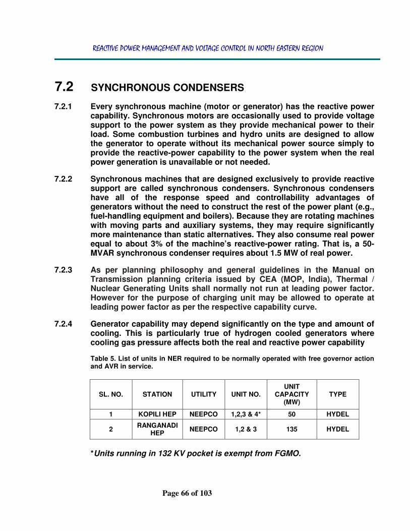
REACTIVE POWER MANAGEMENT AND VOLTAGE CONTROL IN NORTH EASTERN REGION
Page 66 of 103
7.2 SYNCHRONOUS CONDENSERS
7.2.1 Every synchronous machine (motor or generator) has the reactive power capability. Synchronous motors are occasionally used to provide voltage support to the power system as they provide mechanical power to their load. Some combustion turbines and hydro units are designed to allow the generator to operate without its mechanical power source simply to provide the reactive-power capability to the power system when the real power generation is unavailable or not needed.
7.2.2 Synchronous machines that are designed exclusively to provide reactive support are called synchronous condensers. Synchronous condensers have all of the response speed and controllability advantages of generators without the need to construct the rest of the power plant (e.g., fuel-handling equipment and boilers). Because they are rotating machines with moving parts and auxiliary systems, they may require significantly more maintenance than static alternatives. They also consume real power equal to about 3% of the machine’s reactive-power rating. That is, a 50-MVAR synchronous condenser requires about 1.5 MW of real power.
7.2.3 As per planning philosophy and general guidelines in the Manual on Transmission planning criteria issued by CEA (MOP, India), Thermal / Nuclear Generating Units shall normally not run at leading power factor. However for the purpose of charging unit may be allowed to operate at leading power factor as per the respective capability curve.
7.2.4 Generator capability may depend significantly on the type and amount of cooling. This is particularly true of hydrogen cooled generators where cooling gas pressure affects both the real and reactive power capability
Table 5. List of units in NER required to be normally operated with free governor action and AVR in service.
SL. NO. STATION UTILITY UNIT NO. UNIT
CAPACITY (MW)
TYPE
1 KOPILI HEP NEEPCO 1,2,3 & 4* 50 HYDEL
2 RANGANADI
HEP NEEPCO 1,2 & 3 135 HYDEL
*Units running in 132 KV pocket is exempt from FGMO.

REACTIVE POWER MANAGEMENT AND VOLTAGE CONTROL IN NORTH EASTERN REGION
Page 67 of 103
1. LTPS UNIT 5, 6 & 7 CAPABILITY CURVE

REACTIVE POWER MANAGEMENT AND VOLTAGE CONTROL IN NORTH EASTERN REGION
Page 68 of 103
2. NTPS UNIT 1, 2 & 3 CAPABILITY CURVE
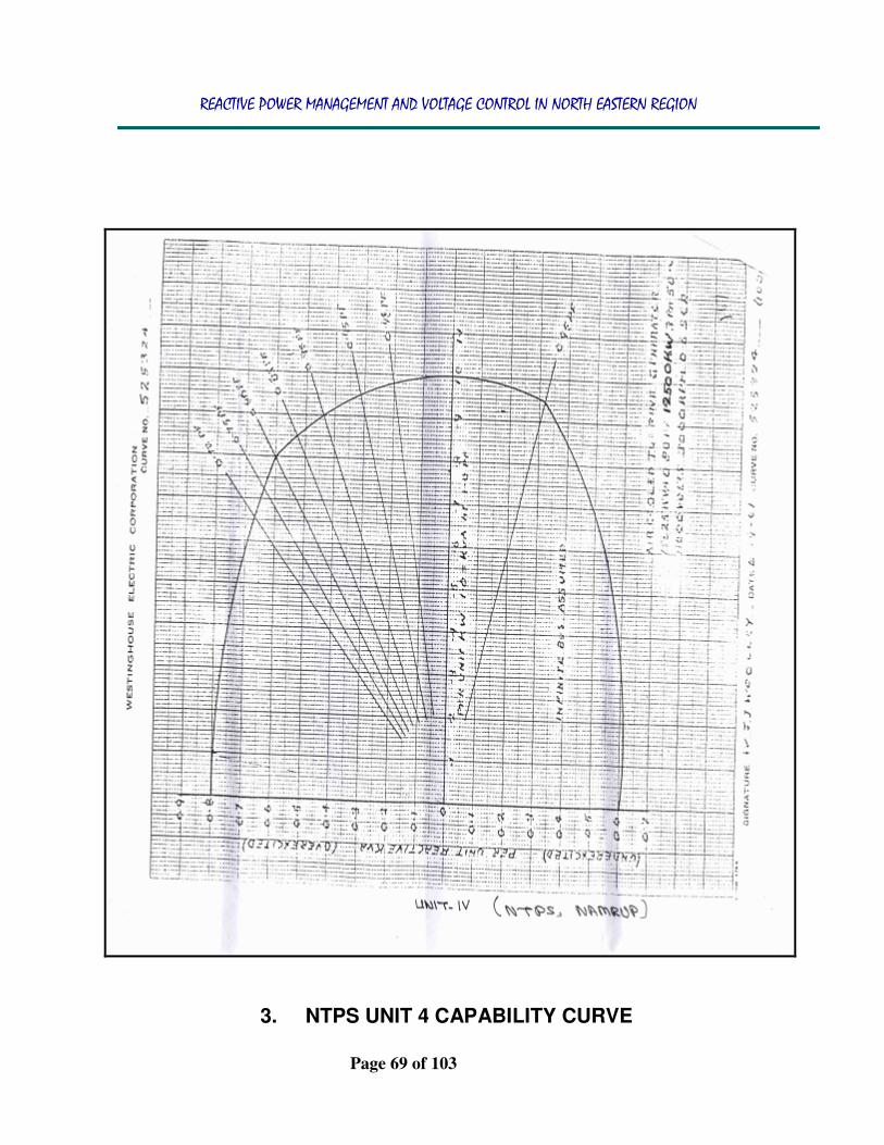
REACTIVE POWER MANAGEMENT AND VOLTAGE CONTROL IN NORTH EASTERN REGION
Page 69 of 103
3. NTPS UNIT 4 CAPABILITY CURVE

REACTIVE POWER MANAGEMENT AND VOLTAGE CONTROL IN NORTH EASTERN REGION
Page 70 of 103
4. NTPS UNIT 6 CAPABILITY CURVE
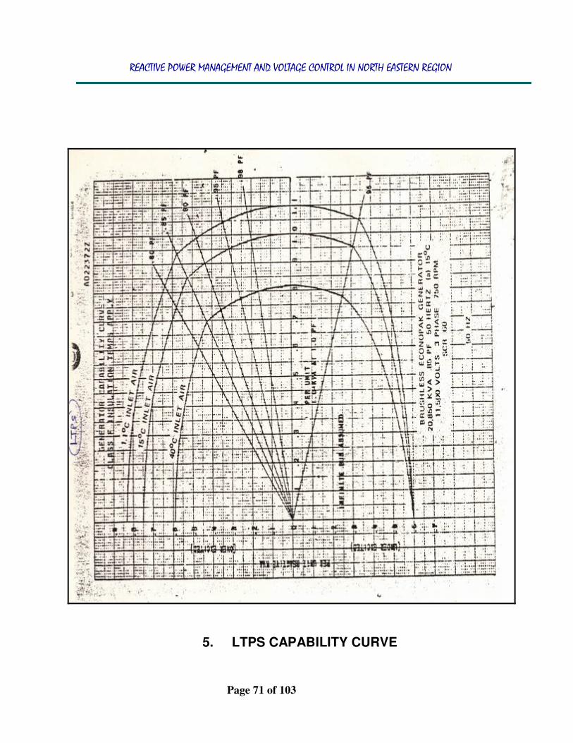
REACTIVE POWER MANAGEMENT AND VOLTAGE CONTROL IN NORTH EASTERN REGION
Page 71 of 103
5. LTPS CAPABILITY CURVE

REACTIVE POWER MANAGEMENT AND VOLTAGE CONTROL IN NORTH EASTERN REGION
Page 72 of 103
6. NTPS CAPABILITY CURVE

REACTIVE POWER MANAGEMENT AND VOLTAGE CONTROL IN NORTH EASTERN REGION
Page 73 of 103
7. UMIUM ST I CAPABILITY CURVE

REACTIVE POWER MANAGEMENT AND VOLTAGE CONTROL IN NORTH EASTERN REGION
Page 74 of 103
8. UMIUM STAGE II CAPABILITY CURVE
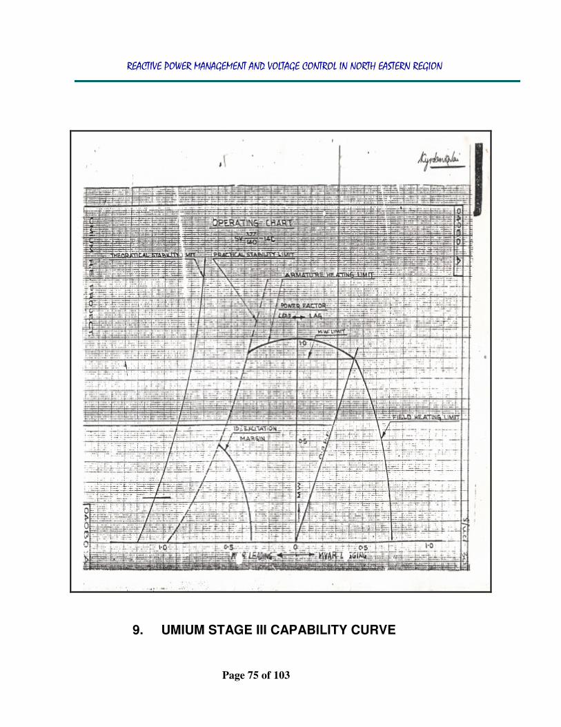
REACTIVE POWER MANAGEMENT AND VOLTAGE CONTROL IN NORTH EASTERN REGION
Page 75 of 103
9. UMIUM STAGE III CAPABILITY CURVE

REACTIVE POWER MANAGEMENT AND VOLTAGE CONTROL IN NORTH EASTERN REGION
Page 76 of 103
10. UMIUM STAGE IV CAPABILITY CURVE
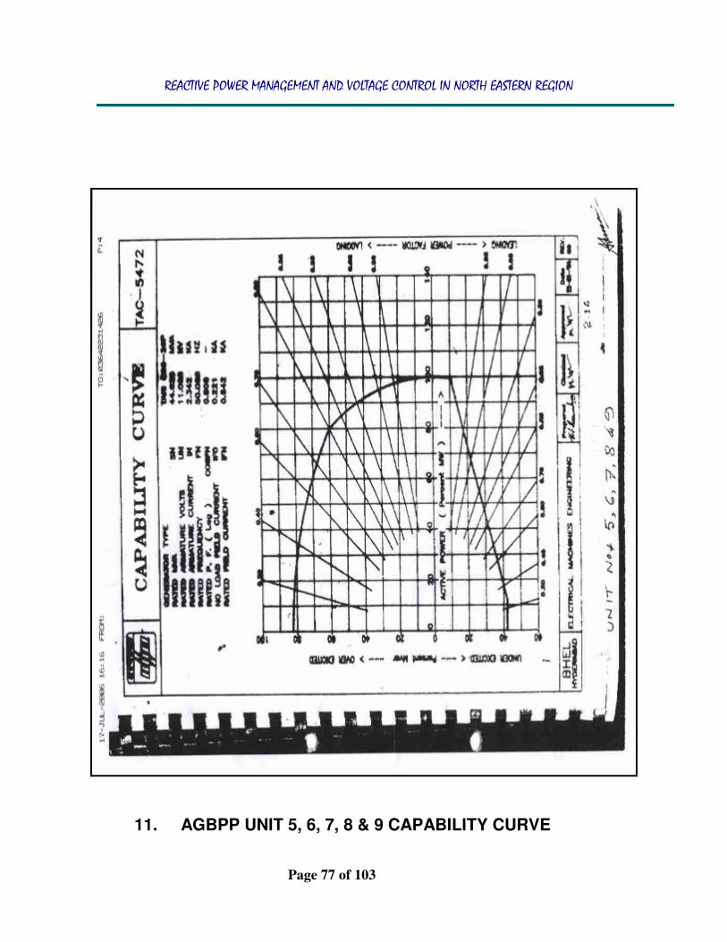
REACTIVE POWER MANAGEMENT AND VOLTAGE CONTROL IN NORTH EASTERN REGION
Page 77 of 103
11. AGBPP UNIT 5, 6, 7, 8 & 9 CAPABILITY CURVE

REACTIVE POWER MANAGEMENT AND VOLTAGE CONTROL IN NORTH EASTERN REGION
Page 78 of 103
12. AGBPP UNIT 1, 2, 3 & 4 CAPABILITY CURVE

REACTIVE POWER MANAGEMENT AND VOLTAGE CONTROL IN NORTH EASTERN REGION
Page 79 of 103
13. AGTPP CAPABILITY CURVE

REACTIVE POWER MANAGEMENT AND VOLTAGE CONTROL IN NORTH EASTERN REGION
Page 80 of 103
14. DOYANG HEP UNIT 1 CAPABILITY CURVE

REACTIVE POWER MANAGEMENT AND VOLTAGE CONTROL IN NORTH EASTERN REGION
Page 81 of 103
15. KHANDONG HEP UNIT 2 CAPABILITY CURVE
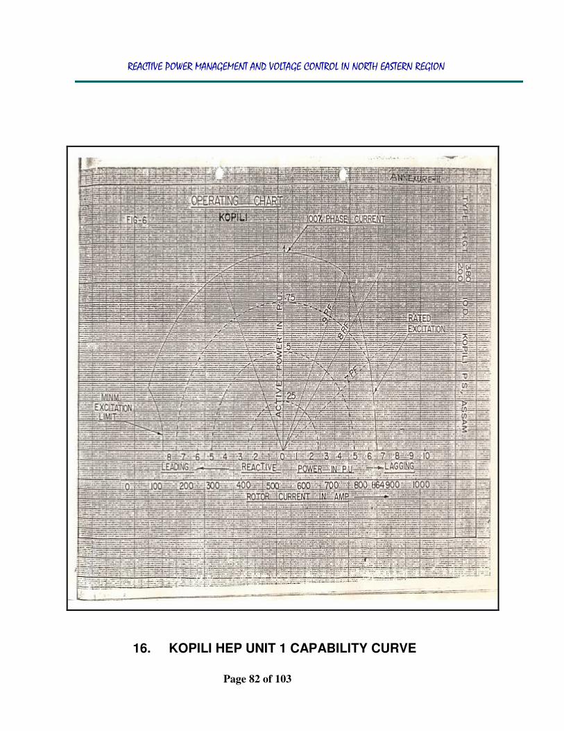
REACTIVE POWER MANAGEMENT AND VOLTAGE CONTROL IN NORTH EASTERN REGION
Page 82 of 103
16. KOPILI HEP UNIT 1 CAPABILITY CURVE

REACTIVE POWER MANAGEMENT AND VOLTAGE CONTROL IN NORTH EASTERN REGION
Page 83 of 103
17. KOPILI HEP UNIT 2 CAPABILITY CURVE

REACTIVE POWER MANAGEMENT AND VOLTAGE CONTROL IN NORTH EASTERN REGION
Page 84 of 103
18. KOPILI HEP ST II CAPABILITY CURVE

REACTIVE POWER MANAGEMENT AND VOLTAGE CONTROL IN NORTH EASTERN REGION
Page 85 of 103
19. RANGANADI HEP CAPABILITY CURVE

REACTIVE POWER MANAGEMENT AND VOLTAGE CONTROL IN NORTH EASTERN REGION
Page 86 of 103
20. LOKTAK HEP CAPABILITY CURVE

REACTIVE POWER MANAGEMENT AND VOLTAGE CONTROL IN NORTH EASTERN REGION
Page 87 of 103
21. ROKHIA UNIT 3, 4 & 6 CAPABILITY CURVE

REACTIVE POWER MANAGEMENT AND VOLTAGE CONTROL IN NORTH EASTERN REGION
Page 88 of 103
22. ROKHIA & BARAMURA CAPABILITY CURVE

REACTIVE POWER MANAGEMENT AND VOLTAGE CONTROL IN NORTH EASTERN REGION
Page 89 of 103
23. OTPC PALATANA GTG CAPABILITY CURVE

REACTIVE POWER MANAGEMENT AND VOLTAGE CONTROL IN NORTH EASTERN REGION
Page 90 of 103
24. OTPC PALATANA STG CAPABILITY CURVE

REACTIVE POWER MANAGEMENT AND VOLTAGE CONTROL IN NORTH EASTERN REGION
Page 91 of 103
8 CONCLUSION
8.1 Generators, synchronous condensers, SVCs, and STATCOMs all provide fast, continuously controllable reactive support and voltage control. LTC transformers provide nearly continuous voltage control but they are slow because the transformer moves reactive power from one bus to another, the control gained at one bus is at the expense of the other. Capacitors and inductors are not variable and offer control only in large steps.
8.2 An unfortunate characteristic of capacitors and capacitor-based SVCs is that output drops dramatically when voltage is low and support is needed most. The output of a capacitor, and the capacity of an SVC, is proportional to the square of the terminal voltage. STATCOMs provide more support under low-voltage conditions than capacitors or SVCs do because they are current-limited devices and their output drops linearly with voltage.
8.3 The output of rotating machinery (i.e., generators and synchronous condensers) rises with dropping voltage unless the field current is actively reduced. Generators and synchronous condensers generally have additional emergency capacity that can be used for a limited time. Voltage-control characteristics favour the use of generators and synchronous condensers. Costs, on the other hand, favor capacitors.
8.4 Generators have extremely high capital costs because they are designed to produce real power, not reactive power. Even the incremental cost of obtaining reactive support from generators is high, although it is difficult to unambiguously separate reactive-power costs from real-power costs. Operating costs for generators are high as well because they involve real-power losses. Finally, because generators have other uses, they experience opportunity costs when called upon to simultaneously provide high levels of both reactive and real power.
8.5 Synchronous condensers have the same costs as generators but, because they are built solely to provide reactive support, their capital costs do not include the prime mover or the balance of plant and they incur no opportunity costs. SVCs and STATCOMs are high-cost devices, as well, although their operating costs are lower than those for synchronous condensers and generators.
REACTIVE POWER MANAGEMENT AND VOLTAGE CONTROL IN NORTH EASTERN REGION
Page 92 of 103
9 SUMMARY
9.1 The process of controlling voltages and managing reactive power on interconnected transmission systems is well understood from a technical perspective. Three objectives dominate reactive-power management. First, maintain adequate voltages throughout the transmission system under current and contingency conditions. Second, minimize congestion of real-power flows. Third, minimize real-power losses.
9.2 This process must be performed centrally because it requires a comprehensive view of the power system to assure that control is coordinated. System operators and planners use sophisticated computer models to design and operate the power system reliably and economically. Central control by rule works well but may not be the most technically and economically effective means.
9.3 The economic impact of control actions can be quite different in a restructured/regulated industry than for vertically integrated utilities. While it may be sufficient to measure only the response of the system in aggregate for a vertically integrated utility, determining individual generator performance will be critical in a competitive environment.
9.4 While it reduces or eliminates opportunity costs by providing sufficient capacity, it can waste capital. When an investor is considering construction of new generation, the amount of reactive capability that the generator can provide without curtailing real-power production should depend on system requirements and the economics of alternatives, not on a fixed rule.
9.5 The introduction of advanced devices, such as STATCOMs and SVCs, further complicates the split between transmission- and generation based voltage control. The fast response of these devices often allows them to substitute for generation-based voltage control. But their high capital costs limit their use. If these devices could participate in a competitive voltage-control market, efficient investment would be encouraged.
9.6 In areas with high concentrations of generation, sufficient interaction among generators is likely to allow operation of a competitive market. In other locations, introduction of a small amount of controllable reactive support on the transmission system might enable market provision of the bulk of the reactive support. In other locations, existing generation would be able to exercise market power and would continue to require economic regulation for this service.

REACTIVE POWER MANAGEMENT AND VOLTAGE CONTROL IN NORTH EASTERN REGION
Page 93 of 103
9.7 A determination of the extent of each type within each region would be a
useful contribution to restructuring. System planners and operators need to work closely together during the design of new facilities and modification of existing facilities. Planners must design adequate reactive support into the system to provide satisfactory voltage profiles during normal and contingency operating conditions. Of particular importance is sufficient dynamic support, such as the reactive output of generators, which can supply additional reactive power during contingencies.
9.8 System operators must have sufficient metering and analytical tools to be able to tell when and if the operational reactive resources are sufficient. Operators must remain cognizant of any equipment outages or problems that could reduce the system’s static or dynamic reactive support below desirable levels. Ensuring that sufficient reactive resources are available in the grid to control voltages may be increasingly difficult because of the disintegration of the electricity industry.
9.9 Traditional vertically integrated utilities contained, within the same entity, generator reactive resources, transmission reactive resources, and the control center that determined what resources were needed when. Presently, these resources and functions are placed within three different entities. In addition, these entities have different, perhaps conflicting, goals. In particular, the owners of generating resources will be driven, in competitive generation markets, to maximize the earnings from their resources. They will not be willing to sacrifice revenues from the sale of real power to produce reactive power unless appropriately compensated.
9.10 Similarly, transmission owners will want to be sure that any costs they incur to expand the reactive capabilities on their system (e.g., additional capacitors) will be reflected fully in the transmission rates that they are allowed to charge.
9.11 Failure to appropriately compensate those entities that provide voltage-control services could lead to serious reliability problems and severe constraints on inter regional links and other congested areas as TTC (Total Transfer Capability) has a voltage limit function as a baggage with it which is directly linked to var compensation. With dynamic ATC’s (Available Transfer capability), Var compensation if not seriously thought of may have serious commercial implications in time to come due to the amount of bulk power trading happening across the country in today’s context.

REACTIVE POWER MANAGEMENT AND VOLTAGE CONTROL IN NORTH EASTERN REGION
Page 94 of 103
10 Statutory Provisions for Reactive Power
Management and voltage Control
10.1 Provision in the Central Electricity Authority (Technical Standard for connectivity to the grid) Regulations 2007 [8]:
Extracts from this standard is as reproduced below for ready reference.
Part II : Grid Connectivity Standards applicable to the Generating Units The units at a generating station proposed to be connected to the grid shall comply with the following requirements besides the general connectivity conditions given in the regulations and general requirements given in part-I of the Schedule:-
1. New Generating Units Hydro generating units having rated capacity of 50 MW and above shall be capable of operation in synchronous condenser mode, where ever feasible.
2. Existing Units For thermal generating unit having rated capacity of 200 MW and above and hydro units having rated capacity of 100 MW and above, the following facilities would be provided at the time of renovation and modernization.
(1) Every generating unit shall have Automatic Voltage Regulator. Generators having rated capacity of 100 MW and above shall have Automatic Voltage Regulator with two separate with two separate channels having independent inputs and automatic changeover.
10.2 Provision in The Indian Electricity Grid Code (IEGC), 2010:
10.2.1 As per sec 3.5 of IEGC planning criterion general policy
(a) The planning criterion are based on the security philosophy on which the ISTS has been planned. The security philosophy may be as per the Transmission Planning Criteria and other guidelines as given by CEA. The general policy shall be as detailed below:
i) As a general rule, the ISTS shall be capable of withstanding and be secured against the following contingency outages

REACTIVE POWER MANAGEMENT AND VOLTAGE CONTROL IN NORTH EASTERN REGION
Page 95 of 103
a. without necessitating load shedding or rescheduling
of generation during Steady State Operation: - Outage of a 132 kV D/C line or, - Outage of a 220 kV D/C line or, - Outage of a 400 kV S/C line or, - Outage of single Interconnecting
Transformer, or - Outage of one pole of HVDC Bipole line, or
one pole of HVDC back to back Station or - Outage of 765 kV S/C line.
b. without necessitating load shedding but could be with rescheduling of generation during steady state operation- - Outage of a 400 kV S/C line with TCSC, or - Outage of a 400kV D/C line, or - Outage of both pole of HVDC Bipole line or
both poles of HVDC back to back Station or - Outage of a 765kV S/C line with series
compensation.
ii) The above contingencies shall be considered assuming a pre-contingency system depletion (Planned outage) of another 220 kV D/C line or 400 kV S/C line in another corridor and not emanating from the same substation. The planning study would assume that all the Generating Units may operate within their reactive capability curves and the network voltage profile shall also be maintained within voltage limits specified
(e) CTU shall carry out planning studies for Reactive Power compensation of ISTS including reactive power compensation requirement at the generator’s /bulk consumer’s switchyard and for connectivity of new generator/ bulk consumer to the ISTS in accordance with Central Electricity Regulatory Commission ( Grant of Connectivity, Long-term Access and Medium-term Open Access in inter-state Transmission and related matters) Regulations, 2009.
10.2.2 As per Sec 4.6.1 of IEGC, Important Technical Requirements for Connectivity to the Grid:
Reactive Power Compensation
a) Reactive Power compensation and/or other facilities, shall be provided by STUs, and Users connected to ISTS as far as possible in the low voltage systems close to the load

REACTIVE POWER MANAGEMENT AND VOLTAGE CONTROL IN NORTH EASTERN REGION
Page 96 of 103
points thereby avoiding the need for exchange of Reactive
Power to/from ISTS and to maintain ISTS voltage within the specified range.
b) The person already connected to the grid shall also provide
additional reactive compensation as per the quantum and time frame decided by respective RPC in consultation with RLDC. The Users and STUs shall provide information to RPC and RLDC regarding the installation and healthiness of the reactive compensation equipment on regular basis. RPC shall regularly monitor the status in this regard.
10.2.3 In chapter 5 of IEGC operating code for regional grids:
5.2(k) All generating units shall normally have their automatic voltage regulators (AVRs) in operation. In particular, if a generating unit of over fifty (50) MW size is required to be operated without its AVR in service, the RLDC shall be immediately intimated about the reason and duration, and its permission obtained. Power System Stabilizers (PSS) in AVRs of generating units (wherever provided), shall be got properly tuned by the respective generating unit owner as per a plan prepared for the purpose by the CTU/RPC from time to time. CTU /RPC will be allowed to carry out checking of PSS and further tuning it, wherever considered necessary.
5.2(o) All Users, STU/SLDC , CTU/RLDC and NLDC, shall also facilitate identification, installation and commissioning of System Protection Schemes (SPS) (including inter-tripping and run-back) in the power system to operate the transmission system closer to their limits and to protect against situations such as voltage collapse and cascade tripping, tripping of important corridors/flow-gates etc.. Such schemes would be finalized by the concerned RPC forum, and shall always be kept in service. If any SPS is to be taken out of service, permission of RLDC shall be obtained indicating reason and duration of anticipated outage from service.
5.2(s) All Users, RLDC, SLDC STUs , CTU and NLDC shall take all possible measures to ensure that the grid voltage always remains within the following operating range.

REACTIVE POWER MANAGEMENT AND VOLTAGE CONTROL IN NORTH EASTERN REGION
Page 97 of 103
Table 6: IEGC operating voltage range 5.2(u) (ii) During the wind generator start-up, the wind generator
shall ensure that the reactive power drawl (inrush currents incase of induction generators) shall not affect the grid performance.
10.2.4 In chapter 6 of IEGC Section-6.6 Reactive Power & Voltage Control:
1. Reactive power compensation should ideally be provided locally, by generating reactive power as close to the reactive power consumption as possible. The Regional Entities except Generating Stations are therefore expected to provide local VAr compensation/generation such that they do not draw VArs from the EHV grid, particularly under low-voltage condition. To discourage VAr drawals by Regional Entities except Generating Stations, VAr exchanges with ISTS shall be priced as follows:
- The Regional Entity except Generating Stations pays
for VAr drawal when voltage at the metering point is below 97%
- The Regional Entity except Generating Stations gets
paid for VAr return when voltage is below 97% - The Regional Entity except Generating Stations gets
paid for VAr drawal when voltage is above103%
Voltage – (KV rms)
Nominal Maximum Minimum
765 800 728
400 420 380
220 245 198
132 145 122
110 121 99
66 72 60
33 36 30

REACTIVE POWER MANAGEMENT AND VOLTAGE CONTROL IN NORTH EASTERN REGION
Page 98 of 103
The Regional Entity except Generating Stations pays for VAr return when voltage is above 103% Provided that there shall be no charge/payment for VAr drawal/return by a regional Entity except Generating Stations on its own line emanating directly from an ISGS.
2. The charge for VArh shall be at the rate of 10 paise/kVArh
w.e.f. 1.4.2010, and this will be applicable between the Regional Entity, except Generating Stations, and the regional pool account for VAr interchanges. This rate shall be escalated at 0.5paise/kVArh per year thereafter, unless otherwise revised by the Commission.
3 Notwithstanding the above, RLDC may direct a Regional
Entity except Generating Stations to curtail its VAr drawal/injection in case the security of grid or safety of any equipment is endangered.
4. In general, the Regional Entities except Generating Stations
shall endeavor to minimize the VAr drawal at an interchange point when the voltage at that point is below 95% of rated, and shall not return VAr when the voltage is above 105%. ICT taps at the respective drawal points may be changed to control the VAr interchange as per a Regional Entity except Generating Stations’s request to the RLDC, but only at reasonable intervals.
5. Switching in/out of all 400 kV bus and line Reactors
throughout the grid shall be carried out as per instructions of RLDC. Tap changing on all 400/220 kV ICTs shall also be done as per RLDCs instructions only.
6. The ISGS and other generating stations connected to
regional grid shall generate/absorb reactive power as per instructions of RLDC, within capability limits of the respective generating units, that is without sacrificing on the active generation required at that time. No payments shall be made to the generating companies for such VAr generation/absorption.
7. VAr exchange directly between two Regional Entities
except Generating Stations on the interconnecting lines owned by them (singly or jointly) generally address or cause a local voltage problem, and generally do not have an impact on the voltage profile of the regional grid. Accordingly, the management/control and commercial handling of the VAr exchanges on such lines shall be as per following provisions, on case-by-case basis:
REACTIVE POWER MANAGEMENT AND VOLTAGE CONTROL IN NORTH EASTERN REGION
Page 99 of 103
i) The two concerned Regional Entities except Generating Stations may mutually agree not to have any charge/payment for VAr exchanges between them on an interconnecting line.
ii) The two concerned Regional Entities except Generating
Stations may mutually agree to adopt a payment rate/scheme for VAr exchanges between them identical to or at variance from that specified by CERC for VAr exchanges with ISTS. If the agreed scheme requires any additional metering, the same shall be arranged by the concerned Beneficiaries.
iii) In case of a disagreement between the concerned
Regional Entities except Generating Stations (e.g. one party wanting to have the charge/payment for VAr exchanges, and the other party refusing to have the scheme), the scheme as specified in Annexure-2 shall be applied. The per kVArh rate shall be as specified by CERC for VAr exchanges with ISTS.
iv) The computation and payments for such VAr exchanges
shall be effected as mutually agreed between the two Beneficiaries.
10.3 THE AEGCL GAZETTE, EXTRAORDINARY, FEBRUARY 10, 2005
10.3.1 IN CHAPTER 9: FREQUENCY AND VOLTAGE MANAGEMENT 10.3.1.1 (9.1) Introduction
(a) This section describes the method by which all Users of the State Grid shall cooperate with SLDC in contributing towards effective control of the system frequency and managing the grid voltage.
(b) State Grid normally operates in synchronism with the North-
Eastern Regional Grid and NERLDC has the overall responsibility of the integrated operation of the North-Eastern Regional Power System. The constituents of the Region are required to follow the instructions of NERLDC for the backing down generation, regulating loads, MVAR drawal etc. to maintain the system frequency and the grid voltage.

REACTIVE POWER MANAGEMENT AND VOLTAGE CONTROL IN NORTH EASTERN REGION
Page 100 of 103
(c) SLDC shall instruct SSGS to regulate Generation/Export and hold reserves of active and reactive power within their respective declared parameters. SLDC shall also regulate the load as may be necessary to meet the objective.
(d) System voltages levels can be affected by Regional operation. The SLDC shall optimise voltage management by adjusting transformer taps to the extent available and switching of circuits/ capacitors/ reactors and other operational steps. SLDC will instruct generating stations to regulate MVAr generation within their declared parameters. SLDC shall also instruct Distribution Licensees to regulate demand, if necessary.
10.3.1.2 (9.2) Objective The objectives of this section are as follows:
(a) To define the responsibilities of all Users in contributing to frequency and voltage management.
(b) To define the actions required to enable SLDC to maintain System voltages and frequency within acceptable levels in accordance Planning and Security Standards of IEGC.
10.3.1.3 (9.3) Frequency Management The rated frequency of the system shall be 50 Hz and shall normally be regulated within the limits prescribed in IEGC Clause 4.6(b). As a constituent of North-Eastern Region, the SLDC shall make all possible efforts to ensure that grid frequency remain within normal band of 49.5 – 50.2Hz (Presently IEGC band is 49.7-50.2 Hz).
10.3.1.4 (9.4) Basic philosophy of control Frequency being essentially the index of load-generation balance conditions of the system, matching of available generation with load, is the only option for maintaining frequency within the desired limits. Basically, two situations arise, viz., a surplus situation and a deficit situation. The automatic mechanisms available for adjustment of load/generation are (i) Free governor action; (ii) Maintenance of spinning reserves and (iii) Under-frequency relay actuated shedding. These measures are essential elements of system security. SLDC shall ensure that Users of the State Grid comply with provisions of clause 6.2 of the IEGC so far as they apply to them. The SLDC in coordination with Users shall exercise the manual mechanism for frequency control under following situations:
10.3.1.5 (9.5) Falling frequency:

REACTIVE POWER MANAGEMENT AND VOLTAGE CONTROL IN NORTH EASTERN REGION
Page 101 of 103
Under falling frequency conditions, SLDC shall take appropriate action to issue instructions, in coordination with NERLDC to arrest the falling frequency and restore it to be within permissible range. Such instructions may include dispatch instruction to SSGS and/or instruction to Distribution Licensees and Open access customers to reduce load demand by appropriate manual and/or automatic load shedding.
10.3.1.6 (9.6) Rising Frequency Under rising frequency conditions, SLDC shall take appropriate action to issue instructions to SSGS in co-ordination with NERLDC, to arrest the rising frequency and restore frequency within permissible range through backing down hydel generation and thermal generation to the level not requiring oil support. SLDC shall also issue instructions to Distribution Licensees and Open access customers in coordination with NERLDC to lift Load shedding (if exists) in order to take additional load.
10.3.1.7 (9.7) Responsibilities SLDC shall monitor actual Drawal against scheduled Drawal and regulate internal generation/demand to maintain this schedule. SLDC shall also monitor reactive power drawal and availability of capacitor banks. Generating Stations within AEGCL shall follow the dispatch instructions issued by SLDC.Distribution Licensees and Open access customers shall co-operate with SLDC in managing load & reactive power drawal on instruction from SLDC as required.
10.3.1.8 (9.8) Voltage Management (a) Users using the Intra State transmission system shall make
all possible efforts to ensure that the grid voltage always remains within the limits specified in IEGC at clause 6.2(q) and produced below:
(b) AEGCL Gridco and/or SLDC shall carry out load flow studies based on operational data from time to time to predict where voltage problems may be encountered and to identify
Nominal Maximum Minimum
400 420 380
220 245 198
132 145 122

REACTIVE POWER MANAGEMENT AND VOLTAGE CONTROL IN NORTH EASTERN REGION
Page 102 of 103
appropriate measures to ensure that voltages remain within the defined limits. On the basis of these studies SLDC shall instruct SSGS to maintain specified voltage level at interconnecting points. SLDC and AEGCL Gridco shall co-ordinate with the Distribution Licensees to determine voltage level at the interconnection points. SLDC shall continuously monitor 400/220/132kV voltage levels at strategic sub-stations to control System voltages.
(c) SLDC in close coordination with NERLDC shall take appropriate measures to control System voltages which may include but not be limited to transformer tap changing, capacitor / reactor switching including capacitor switching by Distribution Licensees at 33 kV substations, operation of Hydro unit as synchronous condenser and use of MVAr reserves with SSGS within technical limits agreed to between AEGCL Gridco and Generators. Generators shall inform SLDC of their reactive reserve capability promptly on request.
(d) APGCL and IPPs shall make available to SLDC the up to date capability curves for all Generating Units, as detailed in Chapter 5.indicating any restrictions, to allow accurate system studies and effective operation of the Intra State transmission system. CPPs shall similarly furnish the net reactive capability that will be available for Export to / Import from Intra State transmission system.
(e) Distribution Licensees and Open access customers shall participate in voltage management by providing Local VAR compensation (as far as possible in low voltage system close to load points) such that they do not depend upon EHV grid for reactive support.
10.3.1.9 (9.9) General
Close co-ordination between Users and SLDC, AEGCL Gridco and NERLDC shall exist at all times for the purposes of effective frequency and voltage management.

REACTIVE POWER MANAGEMENT AND VOLTAGE CONTROL IN NORTH EASTERN REGION
Page 103 of 103
11. Bibliography:
1. Best practice manual of transformer for BEE and IREDA by Devki energy consultancy pvt. ltd.
2. NERPC progress report August, 2010. 3. Document on MeSEB capacity building and training document 4. Manual on Transmission Planning Criteria, CEA, Govt. of India, June 1994 5. Indian Electricity Grid Code, CERC, India, 2010 6. The Central Electricity Authority (Technical Standard for connectivity to the grid)
Regulations 2007. 7. Operation procedure for NER January 2010. 8. Document on Metering code for AEGCL grid. 9. Principles of efficient and reliable reactive power supply and consumption, staff
report, FERC, Docket No. AD05-1-000, February 4, 2005 10. Proceedings of workshop on grid security & management 28
th and 29
th April,
2008 Bangalore. 11. Extra High Voltage AC transmission Engineering – R D Begamudre. 12. Electrical Engineering Handbook – SIEMENS. 13. C. W. Taylor, “Power System Voltage Stability”, McGraw-Hill, 1994. 14. THE AEGCL GAZETTE, EXTRAORDINARY, FEBRUARY 10, 2005

REACTIVE POWER MANAGEMENT AND VOLTAGE CONTROL IN NORTH EASTERN REGION
Page 104 of 103
POWER SYSTEM OPERATION CORPORATION LIMITED (A wholly owned subsidiary of Powergrid)
(A GOVT. OF INDIA UNDERTAKING)
NORTH EASTERN REGIONAL LOAD DESPATCH CENTRE DONGTIEH-LOWER NONGRAH,
LAPALANG,
SHILLONG – 793 006
MEGHALAYA