one break point is enough: traction power simulation in...
TRANSCRIPT

696
LIGHT RAIL ELECTRIFICATION
One Break Point Is Enough Traction Power Simulation in Portland
DENNIS L. PORTER
LTK Engineering Services
THOMAS HEILIG Tri-County Metropolitan Transportation District of Oregon
raction power computer simulation software has changed in the last 20 years. The tool has evolved from simpler, DOS-based, energy management software to detailed, Windows-
based, user friendly, analytical software that can accurately model train performance, predict train voltages, and produce a train voltage profile for an entire rail system. Traction power computer simulation software is now used as a comprehensive design and analysis tool in the development and upgrade of the traction electrification system (TES) for modern rail systems. The software allows the designer to analyze the existing or proposed traction power system under various operating conditions including contingency outage conditions. The designer can also optimize the size and location of the traction power substations as well as the number and size of important components of the overhead contact system (OCS) such as wire, feeder cable, and parallel conductors.
As part of the Interstate MAX Light Rail Project in Portland, Oregon, a number of simulation scenarios were performed for the Tri-County Metropolitan Transportation District of Oregon (TriMet). In TriMet’s case, in addition to developing the TES design for the Interstate MAX Project, the simulations were used to assess whether or not to relocate a major electrical break point within the existing TriMet OCS where the nominal voltage changes from 825 VDC to 750 VDC.
Results from analysis of the simulations led to the basic conclusion not to relocate the breakpoint. Also, the simulations demonstrated the effects that the added operation of the proposed Interstate MAX line would have on the electrical equipment and voltage profiles of the existing system. This type of software makes practical an accurate analysis of the impacts of additional line segments and changes in operating schedules. INTRODUCTION AND OVERVIEW Light Rail in Portland TriMet and the Portland metropolitan area have a 25-year history of involvement with light rail transit (LRT). In the mid-1970s, public officials in Oregon, led by then-Mayor Neil Goldschmidt of Portland, formally withdrew an unbuilt segment of the Interstate Highway System, the Mt Hood Freeway, and, using the provisions of the 1976 Highway Act, substituted proposed transit projects in its place.
T

Porter and Heilig 697
The first transit project to be developed using the Interstate transfer funds was a joint light rail-highway project that ran from downtown Portland 15 mi east to the suburban community of Gresham, generally in a parallel alignment to the deleted Mt. Hood Freeway. This project, known as the Eastside or Banfield Project, included rebuilding the Banfield freeway, an older urban freeway, and re-designating it as Interstate 84. Environmental, planning, and preliminary engineering work was completed in 1980, final design started in 1981, construction commenced in 1982, and the Eastside light rail line opened for revenue service in 1986.
Planning for the second line, the Westside Line, was begun before start of Eastside construction but was placed on hold due to the recession of the early 1980s and the need to successfully complete and demonstrate viability of the first line. The success of the Eastside Line buoyed the resumption of the Westside Line, but it took the region over 4 years to reach consensus on the characteristics of the line and to assure federal funding. Westside final design started in the early 1990s, the Hillsboro extension was added to the project in 1995, and the line opened for revenue service in 1998. The Westside Project was a more complicated line with a 3-mi tunnel and deep station and the introduction of the first, modern low-floor light rail vehicles (LRVs) in North America.
The third project, the Airport line, was a design-build project led by Bechtel in partnership with TriMet, the city of Portland, and the Port of Portland. The airport line opened in 2001.
The most recent project, the Interstate MAX project in north Portland, has its origins in a major funding referendum for a North-South line that failed at the polls in 1998 and was subsequently reconstituted in its current and substantially reduced form. The Interstate MAX line is scheduled to open in 2004.
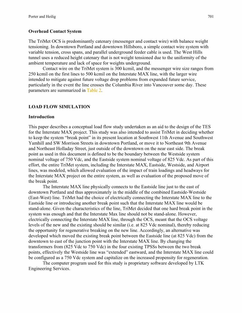
The major characteristics of the TriMet system are summarized in Table 1. The system has grown to almost 45 mi in length (Figure 1), 60 passenger stations, and 105 LRVs, and it exhibits a wide diversity in alignment and station types. The majority of the system is signalized
TABLE 1 TriMet Light Rail System Overview
Eastside Westside Airport Interstate Total (Blue
Line) (Blue Line)
(Red Line)
(Yellow Line)
Start of Revenue Service 1986 1998 2001 2004 N/A Alignment Length (mi) Shared trackway 0.1 0 0 0 0.1 Reserved trackway with at-grade crossings and traffic signals
6.9 2.1 0 4.2 13.2
Reserved trackway with at-grade crossings and gated protection
2.3 9.8 1.4 0.0 13.5
Grade separated trackway 5.8 5.6 4.3 1.6 17.3 Total 15.1 17.5 5.7 5.8 44.1 Single Track Sections (mi) 0 0 1.5 0 1.5 Extent of Automatic Block Signals 55% 90% 100% 35% 70% Peak Hour Headway (min) 6 6 15 10 N/A Typical Consist Length 2 2 1 2 N/A

FIGURE 1 Light rail in Portland.

Porter and Heilig 699
with automatic block signals and magnetic trip stop enforcement. Consist length is limited to two-car trains due to Portland’s short downtown blocks, and rush hour headways range from just under 6 min to 15 min with combined headways as low as 3 min. Service is approximately 21 h a day, 7 days a week, and ridership, prior to introduction of the Interstate MAX line, has increased to over 80,000 boardings a day. Traction Power Substations General Arrangement TriMet has four generations of substations, all slightly different from each other, that are the result of the sequential construction of the four LRT lines discussed above.
The Banfield Line featured compact, packaged traction power substations (TPSSs), and all successive TPSSs have been built-in-place. For the last three projects, the TPSS enclosure has been built under TriMet’s Civil contracts and traction power equipment installed on-site by the TES contractor using licensed electricians.
The physical sizes of the TriMet substations have undergone changes as the light rail system has evolved. The TPSS footprint has grown from approximately 24 ft x 11 ft for the first packaged units to 42 ft x 19 ft for the latest built-in-place unit. Equipment access, arrangement, rating, and conformance to National Electrical Code (NEC) requirements have all played a part in the increased girth of the TPSS.
The AC switchgear in the Banfield and Westside lines is unusual for metal clad switchgear in that it requires access from the front only, thereby permitting the equipment to be installed against the wall, without the need for removable or hinged access panels in the building walls. Similarly, the DC switchgear requires access from the front only and is mounted against the wall. The Interstate MAX substations permit both front and rear access and provide the extra space required. The traction power transformer is located at one end of the substation in the Banfield and Westside arrangement and is located in the line-up between the AC and DC switchgear in the Airport and Interstate MAX substations.
Each TPSS contains an auxiliary power transformer. This transformer always provides auxiliary power to serve the TPSS itself, for lighting, ventilation, battery charger, and other substation auxiliary loads. Additionally, the auxiliary transformer is used to feed hotel power for adjacent passenger stations and other facility loads on most of the Westside line and the Airport line. For Interstate MAX and a few unique locations on the Westside, auxiliary power serves only the TPSS. The auxiliary transformer size and service location vary from project to project. On the original Banfield line, the auxiliary transformer uses a separate feed directly from the utility while all other lines use a separate feed from the AC switchgear.
Grounding System While the original Banfield substations use a single ground mat, the substation grounding system of the subsequent three lines is comprised of two separate ground mats and one separate utility ground rod. The main ground mat, designed to meet the requirements of IEEE 80 to limit step and touch potential to safe levels in the event of a fault on the AC system, is also used to ground the building metallic structure, conduits, and AC equipment, including switchgear. The main ground mat is usually placed under the substation, and extends a minimum of 5 ft beyond the perimeter. Another smaller ground mat referred to as the DC ground mat is used exclusively for

700 Transportation Research Circular E-C058: 9th National Light Rail Transit Conference grounding of the DC equipment, including the negative bus through a diode for stray current monitoring or testing, and for grounding of the DC lightning arresters and protective relays. A separation of 25 ft minimum between the AC and DC mat is used to reduce fault current contribution from the ac equipment to the DC equipment. It also provides for some reduction in DC stray current, when compared to the single ground mat arrangement on the Banfield line. Stray Current Monitoring Each substation is equipped with provisions to monitor stray currents. Within the DC switchgear negative switch cubicle is a measurement shunt and removable bolted bus link in series with the DC grounding conductor. By bolting the link in the closed position, the DC ground mat can be used to ground the negative return through a diode. In this position, the DC ground mat acts as a stray current collector and most stray currents will flow through the shunt. The shunt can be connected to a chart recorder or voltmeter to monitor and record stray currents over time.
In the Westside and Airport substations, a padlocked utility monitoring enclosure is also provided for the purpose of remote monitoring. It is equipped with a 120 Vac receptacle and terminals which TriMet maintenance personnel can connect to the shunt, thereby permitting utilities to remotely monitor stray currents. In the Interstate MAX substations, stray current data is transmitted and recorded using SCADA.
Emergency Shutdown As a safety feature, each substation is equipped with two emergency shutdown stations. One button is recessed in a stainless steel enclosure mounted in an exterior wall of the TPSS, and accessible by key only. The other button is readily accessible and located inside the substation by the access door. Actuation of either button will trip and lock out the 15 kV AC breaker of the substation, and transfer trip and lockout the DC breakers at the adjacent substations, thus completely isolating the fault or trouble. Ratings The TriMet system is served by two local utilities with three-phase AC at 12.5 to 13.8 kV, depending on location. Taps on the traction transformers seek to provide sufficient adjustment to maintain electrical balance in the system.
The 100% full load voltage of the initial Banfield line was set at 825 Vdc. This determination was made in the early 1980s before regenerative braking was commonplace on LRVs—TriMet’s first vehicles did not have regenerative braking capability—and to provide sufficient voltage margin in anticipation of future heavy loads on the system. Subsequently the Westside line, operating through a hilly environment with extended grades, was set at a 100% full voltage of 750 Vdc to provide greater opportunity to capture the benefits of regenerative braking, and the Westside vehicles and subsequent orders have all included a regenerative braking capability.
The traction power substations for the first three lines are all rated at 750 kW, while the Interstate MAX substations are rated at 1 MW (Table 2). TriMet has been very consistent in maintaining an average TPSS spacing of very close to 1 mi, resulting in installed power values from about 0.66 MW per mi on the more lightly loaded Airport line to 1.03 MW per mi on the latest Interstate MAX line.
Porter and Heilig 701 Overhead Contact System The TriMet OCS is predominantly catenary (messenger and contact wire) with balance weight tensioning. In downtown Portland and downtown Hillsboro, a simple contact wire system with variable tension, cross spans, and parallel underground feeder cable is used. The West Hills tunnel uses a reduced height catenary that is not weight tensioned due to the uniformity of the ambient temperature and lack of space for weights underground.
Contact wire on the TriMet system is 300 kcmil, and the messenger wire size ranges from 250 kcmil on the first lines to 500 kcmil on the Interstate MAX line, with the larger wire intended to mitigate against future voltage drop problems from expanded future service, particularly in the event the line crosses the Columbia River into Vancouver some day. These parameters are summarized in Table 2.
LOAD FLOW SIMULATION Introduction This paper describes a conceptual load flow study undertaken as an aid to the design of the TES for the Interstate MAX project. This study was also intended to assist TriMet in deciding whether to keep the system “break point” in its present location at Southwest 11th Avenue and Southwest Yamhill and SW Morrison Streets in downtown Portland, or move it to Northeast 9th Avenue and Northeast Holladay Street, just outside of the downtown on the near east side. The break point as used in this document is defined to be the boundary between the Westside system nominal voltage of 750 Vdc, and the Eastside system nominal voltage of 825 Vdc. As part of this effort, the entire TriMet system, including the Interstate MAX, Eastside, Westside, and Airport lines, was modeled, which allowed evaluation of the impact of train loadings and headways for the Interstate MAX project on the entire system, as well as evaluation of the proposed move of the break point.
The Interstate MAX line physically connects to the Eastside line just to the east of downtown Portland and thus approximately in the middle of the combined Eastside-Westside (East-West) line. TriMet had the choice of electrically connecting the Interstate MAX line to the Eastside line or introducing another break point such that the Interstate MAX line would be stand-alone. Given the characteristics of the line, TriMet decided that one hard break point in the system was enough and that the Interstate Max line should not be stand-alone. However, electrically connecting the Interstate MAX line, through the OCS, meant that the OCS voltage levels of the new and the existing should be similar (i.e. at 825 Vdc nominal), thereby reducing the opportunity for regenerative breaking on the new line. Accordingly, an alternative was developed which moved the existing break point between the Eastside line (at 825 Vdc) from the downtown to east of the junction point with the Interstate MAX line. By changing the transformers from (825 Vdc to 750 Vdc) in the four existing TPSSs between the two break points, effectively the Westside line was “extended” eastward, and the Interstate MAX line could be configured as a 750 Vdc system and capitalize on the increased propensity for regeneration.
The computer program used for this study is proprietary software developed by LTK Engineering Services.

702 Transportation Research Circular E-C058: 9th National Light Rail Transit Conference
TABLE 2 TriMet Traction Electrification System (TES) Overview Eastside Westside Airport Interstate Total Length of line (route miles) 15.1 17.5 5.7 5.8 44.1 Number of TPSSs
— mainline 15 18 5 6 44 — yard 1 1 0 0 2 — shop building 1 1 0 0 2
Average TPSS Spacing on Mainline (miles)
1.0 1.0 1.1 1.0 1.0
100% Full Load Voltage (Vdc) 825 750 825 825 N/A TPSS Nominal Power (kW) 750 750 750 1,000 N/A Total Installed Power on Mainline (MW)
11.250 13.125 3.750 6.000 34.125
Average Installed Power on Mainline (MW per mile)
0.75 0.75 0.66 1.03 0.77
TPSS Enclosure Type Packaged Built-in-place
Built-in-place
Built-in-place
N/A
TPSS Enclosure Size (ft) 26 x 14 38 x 14 39 x 16 42 x 19 N/A Catenary With Weight Tensioning (miles) 13.8 12.3 5.7 5.8 37.6 Without Weight Tensioning (miles)
0.0 3.1 0.0 0.0 3.1
Simple Contact Wire With Weight Tensioning (miles) 1.3 2.1 0 0 3.4 Without Weight Tensioning (miles)
Yard only Yard only 0 0 0
Messenger Wire Size (kcmil) 250 250 250 500 N/A Notes: For Eastside, 1 mainline TPSS added, 1 mainline TPSS re-configured, and 1 yard TPSS upgraded since opening. Parallel underground feeders added in simple contact wire sections.
Methodology and Input Assumptions General Modeling of the TriMet system began with development of a network schematic, which is essentially a single line diagram of the TES. In this schematic, the traction power substations are shown in relation to the overhead contact system, return system, and passenger stations. The network schematic serves as the basis for development of the electrical characterization of the TES.
Porter and Heilig 703
A number of data files describe the track geometry, the permissible speeds, the electrical characteristics of the network, the traction and braking capabilities of the LRVs, and the operating scenarios under investigation.
Description and Assumptions The following parameters were used in this study (“Series” refers to the groupings of computer runs described below):
• The Interstate MAX TPSSs were modeled as 1 MW, 750 Vdc nominal for Series 1 through 4, and 825 Vdc for Series 5 and 6.
• The Westside, Airport, and Banfield TPSSs were modeled as indicated in Table 2. Four of the downtown (Banfield) TPSSs were modeled as 1 MW, 750 Vdc nominal for Series 1 through 4, and 0.75 MW, 825 Vdc full load for Series 5 and 6.
• In general, OCS was modeled as indicated in Table 2, with some exceptions in special cases.
• TPSS feeder cables were modeled as installed, with Interstate MAX using 3—500 kcmil for each positive feeder breaker, which represents an increase in feeder capacity compared to the East-West and Airport lines.
• Rail was taken as 115 RE tee rail (equivalent to Ri 59 girder rail electrically). • All runs used an average contact wire wear of 20%. • All electrical conductor characteristics were taken at approximately 60°C. • Six new Interstate MAX TPSSs [Graham, Overlook, Killingsworth, Buffalo, Portland
International Raceway (PIR), and Expo Center] were modeled. • Track files were constructed using the alignment and profile data available from the
civil design contracts. • Runs were made using the following headways:
East-West 5 min (slight improvement over 2003 service levels) Airport 15 min (average) Interstate MAX 5, 7.5 , and 10 min
• Passenger station dwell time was modeled as 30 s except downtown stations and
major transit centers which were modeled as 60 s, and end of line dwells were set as required to provide the necessary headway and proper operational sequencing.
• All runs were made using a full 60-min electrical simulation, which was delayed until all trains were correctly positioned on the system, thus representing the “peak of the peak.” Car Data Passenger loadings for rail vehicles are typically defined as AW0 (maximum empty vehicle operating weight), AW1 (full seated load, plus operator, plus AW0), AW2 (standees at 4 persons per meter squared of suitable standing area, plus AW1 loading), and higher loadings representing crush conditions rarely encountered in most U.S. transit systems.
The vehicle used for all simulation runs was the Siemens Type 2 Low Floor LRV, which forms the majority of the TriMet fleet. The AW0 weight of the Siemens car was 109,000, and

704 Transportation Research Circular E-C058: 9th National Light Rail Transit Conference with a full AW2 load of 188 passengers at 154 lbs each, the AW2 weight used for simulation was 138,000 lbs.
The car weight in the model was uniformly set to the AW2 weight, which was a conservative assumption (i.e. representing a higher average load than normally achieved), since in actual operations, all trains, especially those in the off-peak direction, do not operate at crowded, AW2 levels along the entire lines.
The car auxiliary load was set at 42 kW, which represents a normal full usage of all vehicle systems, including the HVAC units.
All propulsion and brake rates were assumed to be maximum service rates, and regenerative braking was not modeled since its effects can mask low voltage areas, even though the vehicles have that capability. Actual tractive effort and current curves versus speed for the Siemens cars were used for simulating vehicle performance. The minimum permissible voltage for normal train operation was 525 Vdc, the low voltage set point for the Siemens’ cars.
Consists of two-car trains were used for all simulations, except for the Airport line which was modeled as one car trains.
Series of Runs A total of 54 separate runs were made to evaluate not only the performance of the Interstate MAX TES, but also to evaluate the effects of electrically connecting it to the existing TriMet system and to evaluate the two OCS break points described earlier. To rationalize this approach, the runs have been grouped into six Series as described below. The first four Series are based on the new break point at Northeast 9th and Holladay, while the last two Series are based on the existing break in the downtown area just west of Southwest 11th. Series 1—Interstate MAX Only, with New Break This is one of two Series of Interstate MAX-only runs and contains the standard set of runs first with all Interstate MAX TPSS operational, then with each TPSS respectively dropped out of service one at a time, at headways of both 10 min and 5 min. A TPSS out of service is defined as the AC breaker being open. The substation does not supply power but acts as a tie station utilizing the DC switchgear and cable only. Series 2—Entire System, with New Break, 10 min Interstate MAX Headway This Series adds Interstate MAX at 10-min headways to the existing system and respectively drops out various key substations in the downtown area and on Holladay Street. Two runs simulate bridging the break point at Northeast 9th in an emergency situation when either of the TPSS adjacent to the break point is out of service. Series 3—Entire System, with New Break, 7.5-min Interstate MAX Headway This Series is similar to Series 2 except that Interstate MAX headways are 7.5 min instead of 10 min and there are no runs with the break point bridged. Series 4—Entire System, with New Break, with Parallel Feeder This Series simulates the addition of a new, additional feeder cable along Holladay Street between Rose Quarter and the break at Northeast 9th to mitigate potential “single end feed” problems.

Porter and Heilig 705 Series 5—Entire System with Existing Break, 10-min Interstate MAX Headway This Series is similar to Series 2 except that the OCS break point remains as the existing location at Southwest 11th and the four downtown (Banfield) TPSSs remain as is at 0.75 MW and 825 Vdc nominal. Two runs simulate bridging the existing break point at Southwest 11th in an emergency situation when either of the TPSSs adjacent to the break point is out of service. Series 6—Interstate MAX Only, with Existing Break This Series is similar to Series 1 (Interstate MAX only) except that the OCS break point is the existing location at Southwest 11th
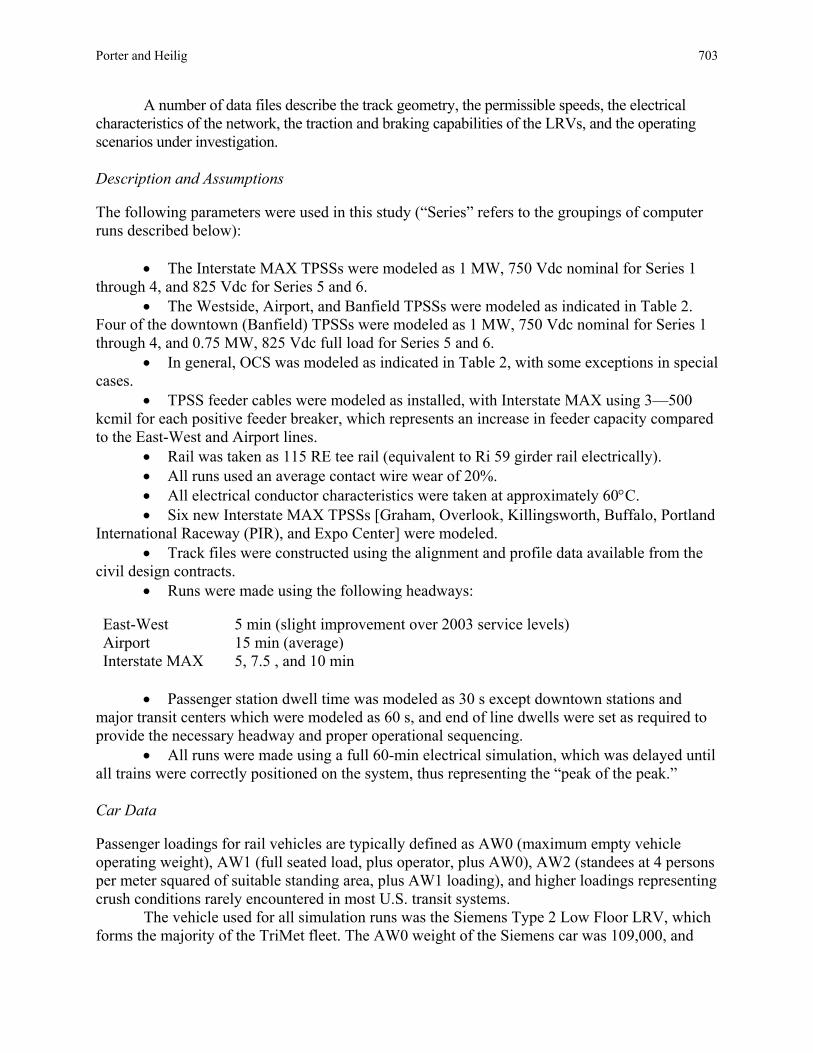
and the four downtown (Banfield) TPSSs remain as is at 0.75 MW and 825 Vdc nominal. Results Voltage Results A brief summary of preliminary voltage results is organized below by Series. The data pertaining to voltages lower than 525 Vdc has been summarized for each Series and presented below. Figure 2 provides a sample output or voltage profile for the East-West line. Series 1—Interstate MAX Only, with New Break No low voltages were detected for all 10-min headway runs and for the 5-min headway run with all TPSSs in service. However, low voltage conditions were predicted when any one of four TPSSs were out of service.
The Series 1 data indicated that considering only the Interstate MAX line and with the break point at the new location of Northeast 9th, the TES will support 10-min headways with all substations in service, and with each individual Interstate MAX substation out of service. The TES will also support 5-min headways with all substations in service. However, the Interstate MAX TES will not support sustained 5-min headways with any specific single substation out of service. This series of runs did not simulate any existing TPSS—for example, from Rose Quarter TPSS to Pioneer Square TPSS—off line.
Series 2—Entire System, with New Break, 10-min Interstate MAX Headway No low voltages were predicted for Interstate MAX, but several instances of low voltage were predicted on the East-West line when any one of several East-West TPSSs was out of service. Voltages along Holladay Street near Rose Quarter were quite low for the one run with the emergency tie connected and Rose Quarter TPSS out.
Series 2 took into consideration the entire TriMet system, and showed slightly below minimum acceptable voltages between the Rose Quarter substation and Lloyd Center substation with all substations in service for 10-min Interstate MAX headways. However, it appears that the influence of the Interstate MAX line on this situation was negligible, and that the low voltages on Holladay Street were due to the combination of the East-West and Airport service levels and the single-end feeding as a result of the new break point. When Rose Quarter substation or Lloyd Center substation was taken out of service, severe low voltages were indicated between these locations. Conversely, the strength of the downtown TES, with the existing break moved to Northeast 9th, was demonstrated by the results showing no low voltages in the downtown when downtown substations were individually taken out of service. Of course, this last result is aided by the removal of any single end feeding in the downtown when the breakpoint was moved to Northeast 9th.

FIGURE 2 Voltage profile.

Porter and Heilig 707
Two runs provided a simulation of an emergency tie that bridged the break at Northeast 9th and connected the two sections with differing voltages together in the event of loss of either Rose Quarter TPSS or Lloyd Center TPSS. In both cases, low voltages were significantly improved, as there was no longer a single-end feed. With the former (i.e., Rose Quarter TPSS out of service), the low voltages rose above the 525 Vdc level, but with the latter, Lloyd Center TPSS out of service, the low voltages remained below 525 Vdc. Series 3—Entire System, with New Break, 7.5-min Interstate MAX headway Similar but slightly worse results than those for Series 2 were predicted. Voltages in the vicinity of the Rose Quarter were quite low.
Series 3 modeled 7.5-min Interstate MAX headways as part of the overall system and showed only very slightly worse voltage conditions than Series 2. Again, there were numerous low voltages along Holladay Street, but no low voltages in the downtown with any one or two substations out of service and no low voltages along the Interstate alignment with all Interstate substations in service. Series 4—Entire System, with New Break, with Parallel Feeder Along Holladay Street No low voltages were detected for the two runs, at 10-min and 7.5-min headways for Interstate MAX, with all TPSS in service, but low voltages along Holladay persisted when the Rose Quarter TPSS was out.
Series 4 investigated using a parallel feeder between the Rose Quarter substation and Northeast 9th to attempt to improve the low voltage condition in that area. Very low voltages still remained at Rose Quarter substation and Northeast 9th with Rose Quarter TPSS out of service even at 10-min Interstate MAX headways (5-min headway East-West and 15-min average headway on the Airport Line).
Series 5—Entire System, with Existing Break, 10-min Interstate MAX headway No low voltages were detected for the run at 10-min headways for Interstate MAX with all TPSSs in service or for the runs with Rose Quarter or Lloyd Center not in service or for the emergency ties. Only one low voltage far removed from Interstate MAX was observed.
Series 5 investigated keeping the system break at its present location at Southwest 11th. With all substations in service, (and headways of 10 min, 5 min, and 15 min for Interstate MAX, East-West, and Airport) no low voltage conditions were encountered on the system. The low voltages along Holladay Street in the Series 2 runs were not present in the Series 5 runs since there is no single end feeding on Holladay Street with the Series 5 runs. With Civic substation out of service, low voltage conditions are encountered at Civic substation. This situation for the existing break was analogous to the single-end feed problem associated with the new break, except that the downtown TES, east of the existing break, is robust enough to maintain acceptable voltages with Pioneer Square out. The emergency tie simulations both resulted in no low voltages below 525 Vdc. Series 6—Interstate MAX Only, with Existing Break No low voltages were detected on any runs.
Series 6 investigated only the Interstate MAX system with the present break location at Southwest 11th, and shows that when considering the Interstate MAX line alone, the system will support 10-min or 5-min headways with any one substation out of service. This result is due to

708 Transportation Research Circular E-C058: 9th National Light Rail Transit Conference the additional 75 Vdc margin when using an 825 Vdc TPSS instead of a 750 Vdc TPSS. Note that this run did not include any of the existing TPSS (i.e., Rose Quarter to Pioneer Square) off line.
TPSS Power Results TriMet”s existing substations are all rated at 750 kW at either 750 Vdc (Westside) or 825 Vdc (Eastside and Airport) nominal. This rating is a continuous rating and the contributing current load can be increased for shorter time intervals, e.g. 150% of full load for 2 h such that effectively the existing TPSS can operate at 1,125 kW for 2 h and somewhat in excess of 1,125 kW for 1 h, but with accompanying temperature rise and potentially transformer and cable insulation degradation. The Interstate MAX TPSS will be rated at 1,000 kW continuous and up to 1,500 kW for 2 h.
The highest estimated TPSS power for each run was tabulated, and in all but one case the highest estimated TPSS power is below 1000 kW. The typical TPSS power is approximately 40% to 50% of rated power. With the Lloyd TPSS out of service, the Hollywood TPSS power is 1,051 kW, still within the rating for a 1-h period, although this is obviously a marginal situation.
Except in one run (full System, new break, Lloyd TPSS out of service), there were no TPSS power problems identified in any of the simulations, at least with the peak loads on a short term basis (1 to 2 h). The results from the marginal run indicate marginally high power levels at Hollywood TPSS that could be sustained only for short durations in an emergency situation.
These results lead to the conclusion that there are no power problems within any of the TriMet TES, including the Interstate MAX line, for any of the conditions simulated.
Feeder Current Results Throughout the TriMet TES, there is considerable diversity in the feeder cable arrangement that connects each TPSS to the OCS. Feeder cables are either 350 kcmil or 500 kcmil or, in a few instances, 750 kcmil. The existing system typically has either two 350 kcmil or two 500 kcmil cables per feeder breaker, while Interstate MAX uses three 500 kcmil cables per feeder breaker. In many cases, particularly in the existing TES, a combination of cables is used. Also, of course the length of feeder cable varies significantly depending on site conditions and is only approximated in most simulations.
Complicating the analysis is the relation of short-term current rating to continuous current rating. The simulation develops a RMS value of current for each feeder connection for the timeframe of the electrical run, i.e. 1 h for all runs in this study. Continuous (3 h) current ratings for cables are readily available from NEC, but short term current levels and durations were not recorded by the model for this report. Therefore, the subsequent heating effects and temperature rises or drops from the varying current loads during the 1-h time frame have not been calculated for each feeder. For this study, to account for high short term currents, a feeder current was considered marginal or worthy of further investigation if the estimated 1-h RMS current approached or exceeded the feeder ampacity rating. Excluding fault current levels, high short term current levels likely contribute to wire fatigue and insulation degradation rather than catastrophic failure—a long term concern rather than a short term one.
High feeder current values for each run were also tabulated. Although there were numerous cases of estimated feeder current exceeding two-thirds of the applicable ampacity rating, the results were divided into three categories.

Porter and Heilig 709
First, for Interstate MAX only at 10-min headways, if either the PIR TPSS or Buffalo TPSS is out of service, marginally high RMS feeder currents approaching 75% of applicable continuous criteria are seen at the other (Buffalo or PIR) TPSS. A similar result is seen at Graham TPSS in Series 2 and 3 when Rose Quarter TPSS is out of service.
Second, for Interstate MAX Only at 5-min headways, all runs show high RMS feeder currents, some in excess of continuous ampacity, at PIR TPSS and Buffalo TPSS. This situation would likely constrain Interstate MAX headways to 7.5 min, but the addition of a new TPSS at Kenton would likely ease or solve this feeder current problem and the voltage problems for Series 1 at 5-min headways identified above.
Third, analysis of marginal feeder conditions for the remainder of the system was beyond the scope of this paper, but it does appear that there are several locations where some marginality is present.
The simulations suggest that marginal or even overloaded conditions exist throughout the system under various TES configurations particularly on lines when headways are at 5 min and substations are taken out of service. These results need to be juxtaposed against some of the conservative assumptions input to the simulations before any general conclusion of inadequate feeder ampacity can be reached. CONCLUSIONS AND RECOMMENDATIONS Interstate MAX Only
• The data show that the Interstate MAX TES as originally configured (with substations at 750 Vdc nominal) would acceptably support 10-min Interstate MAX headways with all substations in service or with any single Interstate MAX substation out of service. Voltages should be well above the 525 Vdc level in most cases but would approach 525 Vdc if either the PIR TPSS or particularly the Buffalo TPSS were out of service. Estimated power is below the substation short term rating in all cases, and estimated RMS feeder currents are below the ampacity ratings.
• Similarly, Interstate MAX headways of 7.5 min and 5 min are achievable with all Interstate MAX substations in service, but numerous voltage and feeder current problems are present at 5-min headways with one substation out of service.
• Addition of another 750 Vdc substation in the vicinity of Kenton will likely be necessary to achieve reliable 5-min Interstate MAX headways with any one substation out of service, and the voltage and feeder current problems with substations out of service should be substantially mitigated. Full System and Break Points
• Moving the break point from Southwest 11th to Northeast 9th and Holladay creates marginally low voltage problems along Holladay St. for normal peak hour operations with all substations in service and very low voltages, well below 525 Vdc, if either Rose Quarter TPSS or Lloyd Center TPSS is out of service.
• Adding a 250 kcmil parallel feeder (per track) from Rose Quarter to Northeast 9th improves voltages such that none is below 525 Vdc with all TPSSs in service, but very low

710 Transportation Research Circular E-C058: 9th National Light Rail Transit Conference voltages remain along Holladay St. if Rose Quarter TPSS is out of service or east of the new break point if Lloyd Center TPSS is out of service.
• An emergency tie across the existing break would raise the voltages to an acceptable level for the one case of Civic TPSS out of service.
• Keeping the break point where it is at present and thus having 825 Vdc nominal Interstate MAX substations also provides significant benefit to Interstate MAX operations, permitting 5-min future headways with any one substation out of service, primarily as a result of the higher nominal voltage of 825 Vdc.
• Results from a separate study demonstrated that savings from regeneration are not reduced significantly by having the higher line voltage on the Eastside. Based on these results and the demonstrated advantages of a higher line voltage from the load flow study, TriMet decided to leave the break point in its present location and build the Interstate Line at the higher Eastside line voltage. General
• Other marginally low voltage conditions were noted on the full system, but were not investigated under this Interstate MAX-focused simulation. Further investigation in these areas has been underway as part of preparatory studies for a new line, the South Line.
• There are always operational responses to TPSS outages, such as slow train orders which limit propulsion rates in affected areas or staggered starts at passenger stations, that may be employed on a “work around” basis.
• Pantograph voltages below 525 Vdc are part of a self-correcting cycle. When a Type 2 LRV experiences a voltage below 525 Vdc, it will (temporarily) shut down propulsion, which removes the load from the TES, which in turn improves the voltage situation, which in turn allows trains to re-start. Thus it is likely that trains can limp out of low voltage areas, although the scenario may not be one to be relied upon as an operating solution.
• A load flow simulation is a valuable tool not only in planning, sizing, and scoping the TES for a new line, but it can also assist a transit agency in making design decisions regarding modifications to its existing system.