on the vehicle functional safety requirements for the
TRANSCRIPT

EN EN
EUROPEAN COMMISSION
Brussels, XXX
C(20..) yyy final
COMMISSION DELEGATED REGULATION (EU) No …/..
of XXX
on the vehicle functional safety requirements for the approval of two- or three-wheel
vehicles and quadricycles
(Text with EEA relevance)

EN 2 EN
COMMISSION DELEGATED REGULATION (EU) No …/..
of xxx
on the vehicle functional safety requirements for the approval of two- or three-wheel vehicles
and quadricycles
(Text with EEA relevance)
THE EUROPEAN COMMISSION,
Having regard to the Treaty on the Functioning of the European Union, and in particular Article 290
thereof,
Having regard to Regulation (EU) No [xxx/2013] of the European Parliament and of the Council on
the approval and market surveillance of two- or three-wheel vehicles and quadricycles1, and in
particular articles 18, 22, 54, 75 and Annex VIII thereof,
Whereas:
(1) The internal market comprises an area without internal frontiers in which the free movement
of goods, persons, services and capital is ensured. To that end, a comprehensive Union type-
approval and a strengthened market surveillance system for L-category vehicles and its
systems, compnents and separate technical units will continue to be applicable as defined by
Regulation (EU) No [xxx/2013] of the European Parliament and of the Council on the
approval and market surveillance of two- or three-wheel vehicles and quadricycles.
(2) The term ‘L-category vehicles’ covers a wide range of different light vehicle types with two,
three or four wheels, e.g. powered cycles, two- and three-wheel mopeds, two- and three-
wheel motorcycles and motorcycles with side-cars. Examples of four-wheel vehicles, also
referred to as quadricycles, are on-road quads, all terrain vehicles and mini-cars.
(3) By Council Decision 97/836/EC the Union has acceded to the Agreement of the United
Nations Economic Commission for Europe (UNECE) concerning the adoption of uniform
technical prescriptions for wheeled vehicles, equipment and parts which can be fitted to
and/or be used on wheeled vehicles and the conditions for reciprocal recognition of
approvals granted on the basis of these prescriptions ('Revised 1958 Agreement')2
(4) By Council Decision 97/836/EC, the Union has also acceded to UNECE regulations Nos 1,
3, 4, 6, 7, 8, 10, 11, 12, 13, 14, 16, 17, 18, 19, 20, 21, 23, 25, 26, 28, 31, 34, 37, 38, 39, 43,
44, 46, 48, 58, 66, 73, 77, 79, 80, 87, 89, 90, 91, 93, 97, 98, 99, 100, and 102.
(5) By Council Decision of 28 February 2000, the Union has acceded to UNECE regulation No
110 on specific components of motor vehicles using compressed natural gas (CNG) in their
propulsion system and on vehicles with regard to the installation of specific components of
an approved type for the use of compressed natural gas (CNG) in their propulsion system.
1 OJ L , , p. . 2 OJ L 346, 17.12.1997, p. 78.
EN 3 EN
(6) By Council Decision 2000/710/EC3, the Union has acceded to UNECE regulation No 67 on
the approval of special equipment for motor vehicles fuelled by liquefied petroleum gas.
(7) In accordance with Regulation (EU) No [xxx/2013], vehicle manufacturers are seeking approval
for L-category vehicles, their systems, components, or separate technical units. Most of the
requirements under Regulations on vehicle parts are taken over from the corresponding
UNECE regulations. As technology progresses, UNECE regulations are constantly amended
and the relevant Union Regulations have to be regularly updated to keep them in line with
the content of the respective UNECE regulations. In order to avoid this duplication, the
CARS 21 High Level Group recommended the replacement of several Union Directives by
the corresponding UNECE regulations.
(8) The possibility to apply UNECE regulations for the purpose of EU vehicle type-approval on a
compulsory basis and to replace Union legislation by those UNECE regulations is provided for in
Regulation (EU) No [xxx/2013]. According to this Regulation type-approval in accordance
with UNECE regulations which apply on a compulsory basis is to be considered as EU type-
approval in accordance with that Regulation and its delegated and implementing acts.
(9) Replacing Union legislation by UNECE regulations helps to avoid duplication not only of
technical requirements but also of certification and administrative procedures. In addition,
type-approval that is directly based on internationally agreed standards should improve
market access in third countries, in particular in those which are contracting parties to the
Revised 1958 Agreement, thus enhancing the Union industry’s competitiveness.
(10) Therefore, Regulation (EU) No [xxx/2013] provides for the repeal of several Union
Directives concerning the type-approval of L-category vehicles, their systems, components
and separate technical units intended therefore, which, for the purposes of EU type-approval
in accordance with that Regulation should be replaced by corresponding UNECE
regulations, the three delegated acts and the implementing act under that Regulation.
(11) For that reason, it is appropriate to include UNECE regulations Nos 1, 3, 4, 6, 7, 8, 10, 14,
16, 17, 18, 19, 20, 23, 26, 28, 30, 31, 34, 37, 38, 39, 43, 44, 45, 46, 48, 53, 54, 55, 56, 57,
60, 62, 64, 67, 72, 74, 75, 76, 77, 78, 81, 82, 87, 90, 91, 97, 98, 99, 100, , 104, 106, 110,
112, 113, 116, 119, 121, 122, 123 and 127 into Annex I to this Regulation, which lists the
UNECE regulations that apply on a compulsory basis.
(12) The UNECE regulations listed in the Annex to this Regulation should apply following the
implementation dates set out in Article 82 of Regulation (EU) No [xxx/2013].
HAS ADOPTED THIS REGULATION:
CHAPTER I
SUBJECT MATTER AND DEFINITIONS
Article 1
Subject matter
This Regulation establishes the technical requirements and test procedures regarding
functional safety for the approval and market surveillance of L-category vehicles and its
systems, components and separate technical units in accordance with Articles 22 and 54 of
Regulation (EU) No [xxx/2013].
3 OJ L 290, 17.11.2000, p. 29.
EN 4 EN
Article 2
Definitions
The definitions of Regulation (EU) No [xxx/2013] shall apply. In addition, the following
definitions shall apply:
Annex II – requirements on audible warning devices
(1) ‘audible warning device’ means a device emitting an acoustic signal intended to give
warning of the presence of or a manoeuvre by a vehicle in a dangerous road traffic
situation and it may consist of several sound emission orifices that are excited by a single
power source as well as several components each emitting an acoustic signal and operating
simultaneously as a result of actuation by a single control.
(2) ‘type of audible warning device’ means audible warning devices not essentially differing
among themselves, particularly in respect of the following aspects: trade mark or name,
operating principle, type of power supply (direct current, alternating current, compressed
air), outer shape of the casing, shape and dimensions of the diaphragm(s), shape or type of
the sound emission orifice(s), nominal sound frequencies, nominal supply voltage, in the
case of warning devices supplied direct by an external source of compressed air: the
nominal operating pressure.
(3) ‘type of vehicle with regard to the audible warning’ means vehicles which do not differ in
such essential respects as: the number of audible warning devices fitted to the vehicle, the
type(s) of audible warning device(s) fitted to the vehicle, the mountings used to fit the
audible warning device(s) to the vehicle, the position and orientation of the audible
warning device(s) on the vehicle, the rigidity of the parts of the structure on which the
audible warning device(s) is/are fitted and the shape and the materials of the bodywork
forming the part of the vehicle which may affect the level of the sound emitted by the
audible warning device(s) and which may have a masking effect;
(4) ‘bodywork’ means the external structure of the motor vehicle which may comprise of
fenders, doors, pillars, side walls, roof, floor, front bulkhead, rear bulkhead and/or other
external panels;
Annex III – requirements on braking, including anti-lock and combined braking systems if
fitted
(5) ‘type of vehicle with regard to braking’ means vehicles which do not differ in such
essential respects as the maximum mass, the distribution of mass between the axles, the
maximum vehicle design speed, the tyre sizes and wheel dimensions, as well as the design
characteristics of the braking system and its components;
Annex IV – requirements on electrical safety
(6) ‘type of vehicle with regard to electrical safety’ means vehicles which do not differ in such
essential respects as the location of conducting parts and components of the entire
electrical system installed in the vehicle;
Annex V – requirements on manufacturer declaration requirements regarding endurance
testing of functional safety critical systems, parts and equipment
(7) ‘type of vehicle with regard to endurance’ means vehicles which do not differ in such
essential respects as the overall design characteristics as well as the vehicle and component
manufacturing and assembly facilities as well as their quality control and assurance
procedures;
Annex VI – requirements on front and rear protective structures

EN 5 EN
(8) ‘type of vehicle with regard to front and rear protective structure’ means vehicles which do
not differ in such essential respects as the shape and location of structures, parts and
components located at the front and rear of the vehicle;
(9) ‘projection’ means the dimension of an edge as determined in accordance with paragraph 2
of Annex 3 to UNECE regulation No 264;
(10) ‘floor line’ means the line as defined in paragraph 2.4. of UNECE regulation No 26;
(11) ‘relevant front structure’ means the part of the front structure which is required to be
present according to this Regulation;
(12) ‘relevant rear structure’ means the part of the rear structure which is required to be present
according to this Regulation;
(13) ‘structure’ means parts such as bodywork, components, fenders, brackets, linkage, tyres,
wheels, wheel guards and glazing, comprising of material with a hardness of at least 60
Shore (A);
Annex VII – requirements on glazing, windscreen wipers and washers, and defrosting and
demisting systems
(14) ‘type of vehicle with regard to glazing, windscreen wipers and washers, and defrosting and
demisting systems’ means vehicles which do not differ in such essential respects as the
shape, size, thickness and characteristics of the windscreen and its mounting, the
characteristics of the wiper and washer system and the characteristics of the defrosting and
demisting systems;
(15) ‘windscreen wiper system’ means the system consisting of a device for wiping the outer
face of the windscreen, together with the accessories and controls necessary for starting
and stopping the device;
(16) ‘wiper field’ means the area(s) on the windscreen which is wiped by the wiper blade(s)
when the wiper system is operating under normal conditions;
(17) ‘windscreen washer system’ means the system consisting of devices for storing,
transferring and aiming fluid towards the outer face of the windscreen, together with the
controls necessary for starting and stopping the device;
(18) ‘washer control’ means the device by which the washer system is manually activated and
deactivated;
(19) ‘washer pump’ means a device for transferring fluid from the washer system storage
reservoir to the outer face of the windscreen;
(20) ‘nozzle’ means a device which serves to direct fluid onto the windscreen;
(21) ‘fully primed system’ means a system which has been activated normally for a period of
time and where fluid has been transferred through the pump, tubing and has exited the
nozzle(s);
(22) ‘cleaned area’ means the previously soiled area which does not have any traces of drops
and remaining dirt after it has dried completely;
(23) ‘vision area A’ means test area A as defined in paragraph 2.2. of Annex 18 to UNECE
Regulation 435;
4 UN regulation 26 first reference 5 UN regulation 43 first reference
EN 6 EN
(24) ‘vehicle master control switch’ means the device by which the vehicle's on-board
electronics system is brought from being switched off, as is the case when a vehicle is
parked without the driver being present, to normal operation mode;
(25) ‘three-dimensional reference system’ means a reference grid which consists of a vertical
longitudinal plane X-Z, a horizontal plane X-Y and a vertical transverse plane Y-Z in
accordance with the provisions of Appendix 2 of Annex III to this Regulation;
Annex VIII – requirements on driver-operated controls including identification of controls,
tell-tales and indicators
(26) ‘type of vehicle with regard to identification of controls, tell-tales and indicators’ means
vehicles which do not differ in such essential respects as the number, location and design
characteristics of controls, tell-tales and indicators as well as the tolerances of the
speedometer’s measuring mechanism, technical constant of the speedometer, range of
speeds displayed, overall transmission ratio, including any reduction drives, to the
speedometer and the minimum and maximum tyre size designations;
(27) ‘control’ means any part of the vehicle or component directly actuated by the driver which
causes a change in the state or operation of the vehicle or one of the parts thereof;
(28) ‘tell-tale’ means an optical signal which indicates the actuation of a device, correct or
defective functioning or condition, or failure to function;
(29) ‘indicator’ means a device providing information on the proper functioning or state of a
system or part of a system such as the level or temperature of a fluid;
(30) ‘speedometer’ means a device indicating to the driver the speed of the vehicle at any given
moment;
(31) ‘odometer’ means a device that indicates the distance traveled by a vehicle;
(32) ‘symbol’ means a diagram from which to identify a control, a tell-tale or an indicator;
(33) ‘common space’ means a specific area such as an information screen on which more than
one tell-tale, indicator, symbol or other information may be displayed;
Annex IX – requirements on installation of lighting and light signalling devices, including
automatic switching of lighting
(34) ‘type of vehicle with regard to on installation of lighting’ means vehicles which do not
differ in such essential respects as the dimensions and outer shape of the vehicle as well as
the number, location and design characteristics of the installed lighting devices and light-
signalling devices;
(35) ‘lighting device’ means a type-approved lamp or type-approved retro-reflector;
(36) ‘light-signalling device’ means a lighting device which may be used for signalling.
(37) ‘single lighting device’ means a lighting device or part of a device, having one function
and one illuminating surface and one or more light sources, however, it may also mean any
assembly of two independent or grouped lighting devices, whether identical or not, having
the same function, if they are installed such that the projections of the light-emitting
surfaces of the lighting devices on a given transverse plane occupy not less than 60 % of
the smallest rectangle circumscribing the projections of the said light-emitting surfaces;
(38) ‘light-emitting surface’ of a lighting device means all or part of the exterior surface of the
translucent material, as stated in the component type-approval documentation, and may
include or entirely consist of the illuminating surface and may also include the area which
is completely circumscribed by the lighting device;
EN 7 EN
(39) ‘illuminating surface’ of a lighting device means the surface as defined in paragraph 2.7. of
UNECE regulation No. 536 as stated in the component type-approval documentation;
(40) ‘independent lighting device’ means a lighting device having a separate illuminating
surface, light source and lamp body;
(41) ‘grouped lighting devices’ means lighting devices having separate illuminating surfaces
and light sources, but a common lamp body;
(42) ‘combined lighting devices’ means lighting devices having separate illuminating surfaces
but a common light source and a common lamp body;
(43) ‘reciprocally incorporated lighting devices’ means lighting devices having separate light
sources or a single light source operating under different conditions (e.g. optical,
mechanical or electrical differences), totally or partially common illuminating surfaces and
a common lamp body;
(44) ‘driving-beam headlamp’ (main-beam headlamp) means the device used to illuminate the
road over a long distance ahead of the vehicle;
(45) ‘passing-beam headlamp’ (dipped-beam headlamp) means the device used to illuminate the
road ahead of the vehicle without causing undue dazzle or discomfort to oncoming drivers
or to other road users;
(46) ‘front position lamp’ means the device used to indicate the presence of the vehicle when
viewed from the front;
(47) ‘daytime running lamp’ means a lamp facing in a forward direction used to make the
vehicle more easily visible when driving during daytime;
(48) ‘front fog lamp’ means the device used to improve the illumination of the road in case of
fog, snowfall, rainstorms or dust clouds;
(49) ‘direction indicator lamp’ means the device used to indicate to other road users that the
driver intends to change direction to the right or the left;
(50) ‘hazard warning signal’ means the simultaneous operation of all of a vehicle's direction
indicator lamps to draw attention to the fact that the vehicle temporarily constitutes a
special danger to other road users;
(51) ‘stop lamp’ means the device used to indicate to other road users to the rear of the vehicle
that the latter's driver is applying the service brake;
(52) ‘rear position lamp’ means the device used to indicate the presence of the vehicle when
viewed from the rear;
(53) ‘rear fog lamp’ means the device used to render the vehicle more readily visible from the
rear in case of fog, snowfall, rainstorms or dust clouds;
(54) ‘reversing lamp’ means the device used to illuminate the road to the rear of the vehicle and
to warn other road users that the vehicle is reversing or about to reverse;
(55) ‘rear registration plate lamp’ means the device used to illuminate the space intended to
accommodate the rear registration plate; it may consist of several optical elements;
(56) ‘rear retro-reflector’ means the retro-reflector device used to indicate the presence of the
vehicle when viewed from the rear;
6 UN regulation 53 first reference
EN 8 EN
(57) ‘side retro-reflector’ means the retro-reflector device used to indicate the presence of the
vehicle when viewed from the side;
(58) ‘retro-reflector’ means the device used to indicate the presence of a vehicle by the
reflection of light emanating from a light source not connected to the vehicle, the observer
being situated near that source (for the purposes of this Regulation, retro-reflecting
registration plates or speed limitation plates are not considered to be retro- reflectors);
(59) ‘side marker lamp’ means the device used to indicate the presence of the vehicle when
viewed from the side;
(60) ‘reference axis’ means the characteristic axis of the device as stated in the component type-
approval documentation for use as the direction of reference (H = 0°, V = 0°) for angles of
field for photometric measurements and when fitting the lamp on the vehicle;
(61) ‘reference centre’ means the intersection of the reference axis with the light-emitting
surface, the centre of reference being specified by the manufacturer of the lighting device;
(62) ‘angles of geometric visibility’ means the angles which determine the square field in which
the light-emitting surface of the lighting device is completely visible when the relevant
angles (α vertical and β horizontal) are measured at the outward contour of the apparent
surface and the lamp is observed from afar, however, if any obstacle is located inside this
field while partly obscuring the light-emmitting surface, it may be accepted when it is
proven that even with such obstructions, the photometric values prescribed for the type-
approval of the lighting device as component are still complied with;
(63) ‘longitudinal median plane of the vehicle’ means the plane of symmetry of the vehicle or,
if the vehicle is not symmetrical, the vertical longitudinal plane passing through the middle
of the vehicle axles;
(64) ‘operating tell-tale’ means a tell-tale or auditory signal indicating that a lighting-device has
been switched on and/or that it is operating correctly or not;
(65) ‘closed-circuit tell-tale’ means a tell-tale indicating that a device has been switched on, but
not indicating whether it is operating correctly or not;
Annex X – requirements on rearward visibility
(66) ‘type of vehicle with regard to rearward visibility’ means vehicles which do not differ in
such essential respects as the dimensions and external shape of the vehicle as well as the
number, location and design characteristics of the installed devices for indirect vision and
rear view mirrors;
Annex XI – on roll-over protective structure (ROPS)
(67) ‘type of vehicle with regard to roll-over protection structure’ means vehicles which do not
differ in such essential respects as the structure on the vehicle the essential purpose of
which is to mitigate or avoid risk of severe injury to the vehicle’s occupants resulting from
a roll-over of the vehicle during normal use;
(68) ‘zone of clearance’ means the space occupied by a 50th
percentile male manikin
represented by the Hybrid III anthropomorphic test device in normal seating position on all
seating positions;
Annex XII – requirements on safety belt anchorages and safety belts
(69) ‘type of vehicle with regard to safety belt anchorages and safety belts’ means vehicles
which do not differ in such essential respects as the main vehicle construction and design

EN 9 EN
characteristics as well as that of the safety belt anchorages and the number, location and
configuration of fitted safety belts;
(70) ‘adjustment system’ means the device enabling the parts of the seat to be adjusted in order
to achieve a seating position that is adapted to the occupant’s morphology, including
longitudinal, vertical and/or angular adjustments;
(71) ‘displacement system’ means an adjustement and locking system such as a folding
seatback fitted to seats in front of other seats, enabeling passengers to access and exit from
such rear seats when there are no doors adjacent to that rear seating row;
(72) ‘saddle’ means a seating position where the rider or passenger sits astride;
(73) ‘seat’ means a seating position which is not a saddle and which has a seat back offering
support for the driver’s or passenger’s back;
(74) ‘seat back’ means a structural element behind the seating position’s R-point at a height of
more than 450 mm measured from the vertical plane passing through the R-point against
which the back of a seated person can rest completely;
(75) ‘50th
percentile xxx add definition;
(76) ‘actual safety belt anchorage’ means a point of the vehicle structure or the seat structure or
any other part of the vehicle to which a safety belt assembly is to be physically mounted;
(77) ‘effective safety belt anchorage’ means a clearly defined point in the vehicle which has
sufficiently rigid properties as to actually change the routing, course and direction of a
safety belt which is worn by the vehicle occupant and comprises of such point which is
closest that portion of the belt which is in actual and direct contact with the wearer;
(78) ‘front seating position’ means a single seating position which may be grouped in a row of
several seating positions;
(79) ‘rear seating position’ means a single seating position located fully behind the line of a
front seating position and which may be grouped in a row of several seating positions;
(80) ‘torso reference line’ means the torso line as defined by the vehicle manufacturer for each
seating position and established in accordance with Annex 3 to UNECE regulation No.
177;
(81) ‘torso angle’ means the angle between the vertical and the torso line;
(82) ‘design position’ means the position in which a device such as a seat can be adjusted so
that it corresponds with all relevant settings in order to achieve the specified position as
closely as possible;
(83) ‘isofix’ means a system for the connection of child restraint systems to vehicles which has
two vehicle rigid anchorages, two corresponding rigid attachments on the child restraint
system and a mean to limit the pitch rotation of the child restraint system;
Annex XIII – requirements on seating positions (saddles and seats)
(84) ‘type of vehicle with regard to seating positions’ means vehicles which do not differ in
such essential respects as the shape, location and number of the seat(s) or saddle(s);
Annex XIV – requirements on steer-ability, cornering properties and turn-ability
7 UN regulation 17 first reference
EN 10 EN
(85) ‘type of vehicle with regard to steer-ability, cornering properties and turn-ability’ means
vehicles which do not differ in such essential respects as the design characteristics of the
steering mechanism, reversing device and locking differentials, if such devices are fitted to
the vehicle;
(86) ‘Turning circle’ means the circle within which are located the projections onto the ground
plane of all the points of the vehicle, excluding rear-view mirrors, when the vehicle is
driven in a circle;
(87) ‘unusual vibration’ means a vibration which differs markedly from a normal and constant
vibration, characterised by one or more unintended sharp increases of the amplitude of the
vibration and which leads to increased steering forces that are not constant and not
predictable in nature;
Annex XV – requirements on the installation of tyres
(88) ‘type of vehicle with regard to the installation of tyres’ means vehicles which do not differ
in such essential respects as the types of tyres, minimum and maximum tyre size
designations, wheel dimensions and off-sets as well as speed and load capabilities suitable
for fitment, and the characteristics of the fitted wheel guards;
(89) ‘wheel off-set’ means the distance from the hub abutment face to the centre line of the rim;
(90) ‘temporary-use spare unit’ means a unit with a tyre different from a tyre intended to be
fitted to any vehicle for normal driving conditions, but intended only for temporary-use
under restricted driving conditions;
(91) ‘maximum load rating’ means the mass which a tyre can carry when operated in
conformity with requirements governing utilisation specified by the tyre manufacturer,
expressed in a load capacity index number;
(92) ‘load capacity index’ means a number associated to the maximum load rating of the tyre in
relation to the definition in paragraph 2.26. of UNECE regulation No. 758, in paragraph
2.28. of UNECE regulation No. 309, paragraph 2.27. of UNECE regulation No. 54
10 and
paragraph 2.28. of UNECE regulation No. 10611
;
(93) ‘speed category symbol’ means the symbol as defined in paragraph 2.28 of UNECE
regulation No. 75, paragraph 2.29. of UNECE regulation No. 30, paragraph 2.28 of
UNECE regulation No. 54 and paragraph 2.29. of UNECE regulation No. 106;
Annex XVI – requirements on vehicle maximum speed limitation plate and its location on
the vehicle
(94) ‘type of vehicle with regard to maximum speed limitation plate and location on the
vehicle’ means vehicles which do not differ in such essential respects as the maximum
vehicle design speed as well as the material, orientation, and design characteristics of the
maximum speed limitation plate;
(95) ‘virtually flat surface’ means a surface of solid material, with a radius of curvature of at
least 5000 mm;
Annex XVII – Requirements on vehicle occupant protection, including interior fittings and
vehicle doors
8 UN regulation 75 first reference 9 UN regulation 30 first reference 10 UN regulation 54 first reference 11 UN regulation 106 first reference OJ L 257, 30.09.2010, p. 231-279

EN 11 EN
(96) ‘vehicle type with regard to vehicle occupant protection, including interior fittings and
vehicle doors’ means vehicles which do not differ in such essential respects as the design
characteristics of the vehicle’s interior fittings as well as the number and location of seats
and doors;
(97) ‘level of the instrument panel’ means the line defined by the points of contact of vertical
tangents to the instrument panel or at the level of the horizontal plane coinciding with the
R-point of the seating position of the driver where the latter is located higher than a tangent
contact point in question;
(98) ‘contactable edges’ means edges which can be contacted by the surface of a testing
apparatus and can consist of structures, elements or components located anywhere in the
vehicle, including and not limited to the passenger compartment floor, sides, doors,
windows, roof, roof pillars, roof ribs, sun visors, instrument panel, steering control, seats,
head restraints, safety belts, levers, knobs, covers, compartments, lights;
(99) ‘door’ means any structure or material which has to be opened, displaced, folded,
unzipped, slid away or manipulated in any other way in order to ingress or egress the
vehicle;
(100) ‘door centre’ means the dimensional location in a vertical plane parallel to the longitudinal
median plane of the vehicle which coincides with the centre of gravity of the door in
question;
Annex XVIII – Requirements on maximum continuous total power and/or vehicle speed
limitation by design
(101) ‘vehicle type with regard to maximum continuous total power and/or vehicle speed
limitation by design’ means vehicles which do not differ in such essential respects as the
maximum continuous power output of the electric motor(s) and/or engine, the vehicle
maximum design speed and the design characteristics of devices and methodology
employed to effectively limit the vehicle’s achievable maximum speed and/or power
output;
(102) ‘different concept and design’ means that a specifically designed measure failing to work
properly does not impair another specifically designed measure;
Annex XIX – Requirements on vehicle structure integrity
(103) ‘vehicle type with regard to vehicle structure integrity’ means vehicles which do not differ
in such essential respects as the design characteristics of the mechanical connections such
as welds and threaded connections as well as the frame, chassis and/or body of the vehicle
and the manner in which it is secured that production vehicles are representative of the
actual vehicle used for type-approval testing by the technical service.
CHAPTER II
OBLIGATIONS OF MANUFACTURERS
Article 3
Manufacturer's obligations
1. In order to comply with the functional safety requirements as laid down in Articles 20 and
Annex II and VIII to Regulation (EU) No [xxx/2013], the manufacturer shall equip L-
category vehicles with systems, components and separate technical units affecting its
functional safety to be designed, constructed and assembled so as to enable the vehicle in
normal use and maintained according to the prescriptions of the manufacturer to comply
EN 12 EN
with the detailed technical requirements and testing procedures In accordance with Articles
5 to 22, the manufacturer shall demonstrate by means of physical demonstration testing to
the approval authority that the L-category vehicles made available on the market,
registered or entering into service in the Union comply with the functional safety
requirements of Articles 18, 22, 54, 75 and Annex VIIIof Regulation (EU) No [xxx/2013]
and comply with the detailed technical requirements and test procedures laid down in this
Regulation.
2. The manufacturer shall demonstrate that replacement devices requiring type approval that
are made available on the market or are entering into service in the Union are approved in
accordance with the requirements of Regulation (EU) No [xxx/2013], as specifed bythe
detailed technical requieremenst and test procedures referred to in this Regulation. An
approved L-category vehicle equipped with such a replacement device shall meet the same
functional safety test requirements and performance limit values than a vehicle equipped
with an original equipment or device up to and including the endurance requierements set
out in paragraph 1a of Article 22 from Regulation (EU) No [xxx/2013].
3. The manufacturer shall submit a description of the provisions taken to prevent tampering
with and modification of the powertrain management system including the functional
safety control computers.
Article 4
Compulsory application of UNECE regulations
In accordance with Article 54 of Regulation (EU) No [xxx/2013] the UNECE regulations
set-out in Annex I shall be part of type-approval and be applicable on a compulsory basis.
Article 5
Technical specifications on functional safety requirements and test procedures
The functional safety performance test procedures shall be performed in accordance with
the test requirements laid down in this Regulation and the tests shall be carried out or
witnessed by the approval authority or, if authorised by the approval authority, by the
technical service. The measurement methods and test results shall be reported to the
approval authority in the format as set out in Regulation (EU) No [xxx/2013] regarding
administrative provisions.
Article 6
Requirements on audible warning devices
The test procedures and performance requirements on audible warning devices referred to
in Annex II (B1) to Regulation (EU) No [xxx/2013] shall be conducted and verified in
accordance with Annex II.
Article 7
Requirements on braking, including anti-lock and combined braking systems if fitted
The test procedures and performance requirements on braking, including anti-lock and
combined braking systems if fitted, referred to in Annex II (B2) and Annex VIII to
Regulation (EU) No [xxx/2013], shall be conducted and verified in accordance with the
requirements laid down in Annex III.

EN 13 EN
Article 8
Requirements on electrical safety
The test procedures and performance requirements on electric safety referred to in Annex
II (B3) of Regulation (EU) No [xxx/2013] shall be conducted and verified in accordance
with the requirements laid down in Annex IV.
Article 9
Requirements on manufacturer declaration requirements regarding endurance testing of
functional safety critical systems, parts and equipment
The manufacturer declaration regarding endurance testing of functional safety systems,
parts and equipment referred to in Annex II (B4) of Regulation (EU) No [xxx/2013] shall
comply with the requirements laid down in Annex V.
Article 10
Requirements on on front and rear protective structures
The test procedures and performance requirements on front and rear protective structures
referred to in Annex II (B5) of Regulation (EU) No [xxx/2013] shall be conducted and
verified in accordance with the requirements laid down in Annex VI.
Article 11
Requirements on glazing, windscreen wipers and washers, and defrosting and demisting systems
The test procedures and performance requirements on glazing, windscreen wipers and
washers, and defrosting and demisting systems referred to in Annex II (B6) of Regulation
(EU) No [xxx/2013] shall be conducted and verified in accordance with the requirements
laid down in Annex VII.
Article 12
Requirements on driver-operated controls including identification of controls, tell-tales and
indicators
The test procedures and performance requirements on driver-operated controls including
identification of controls, tell-tales and indicators referred to in Annex II (B7) of
Regulation (EU) No [xxx/2013] shall be conducted and verified in accordance with the
requirements laid down in Annex VIII.
Article 13
Requirements on installation of lighting and light signalling devices, including automatic
switching of lighting
The test procedures and performance requirements on installation of lighting and light
signalling devices, including automatic switching of lighting referred to in Annex II (B8)
and Annex VIII of Regulation (EU) No [xxx/2013], shall be conducted and verified in
accordance with the requirements laid down in Annex IX.

EN 14 EN
Article 14
Requirements on rearward visibility
The test procedures and measurements in order to test the relevant requirements on
rearward visibility referred to in Annex II (B9) to Regulation (EU) No [xxx/2013] shall be
conducted and verified in accordance with the requirements laid down in Annex X.
Article 15
Requirements on roll-over protective structure
The test procedures and performance requirements on roll-over protective structure
referred to in Annex II (B10) of Regulation (EU) No [xxx/2013] shall be conducted and
verified in accordance with the requirements laid down in Annex XI.
Article 16
Requirements on safety belt anchorages and safety belts
The test procedures and performance requirements on safety belt anchorages and safety
belts referred to in Annex II (B11) of Regulation (EU) No [xxx/2013] shall be conducted
and verified in accordance with the requirements laid down in Annex XII.
Article 17
Requirements on seating position (saddles and seats)
The test procedures and performance requirements on the seating position (saddles and
seats) referred to in Annex II (B12) of Regulation (EU) No [xxx/2013] shall be conducted
and verified in accordance with the requirements laid down in Annex XIII.
Article 18
Requirements on steer-ability, cornering properties and turn-ability
The test procedures and performance requirements on steer-ability, cornering properties
and turn-ability referred to in Annex II (B13) of Regulation (EU) No [xxx/2013] shall be
conducted and verified in accordance with the requirements laid down in Annex XIV.
Article 19
Requirements on the installation of tyres
The test procedures and performance requirements on the installation of tyres referred to in
Annex II (B14) of Regulation (EU) No [xxx/2013] shall be conducted and verified in
accordance with the requirements laid down in Annex XV.
Article 20
Requirements on vehicle maximum vehicle speed limitation plate and its location on vehicle
The test procedures and performance requirements on the maximum vehicle speed
limitation plate and its location on L-category vehicles referred to in Annex II (B15) of
Regulation (EU) No [xxx/2013] shall be conducted and verified in accordance with the
requirements laid down in Annex XVI.
EN 15 EN
Article 21
Requirements on vehicle occupant protection, including interior fittings and vehicle doors
The test procedures and performance requirements on vehicle occupant protection,
including interior fittings and vehicle doors referred to in Annex II (B16) of Regulation
(EU) No [xxx/2013] shall be conducted and verified in accordance with the requirements
laid down in Annex XVII.
Article 22
Requirements on maximum continuous rated and/or net power and/or vehicle speed limitation by
design
The test procedures and performance requirements on the limitation by design of
maximum continuous total rated and/or net power and/or vehicle speed of L-category
vehicles referred to in Annex II (B17) of Regulation (EU) No [xxx/2013] shall be
conducted and verified in accordance with the requirements laid down in Annex XVIII.
Article 23
Requirements on vehicle structure integrity
The requirements on vehicle structure integrity referred to in Annex II (B18) and in Annex
VIII of Regulation (EU) No [xxx/2013] shall be complied with in accordance with the
requirements laid down in Annex XIX.

EN 16 EN
CHAPTER III
OBLIGATIONS OF THE MEMBER STATES
Article 24
Type-approval of vehicles, systems, components and separate technical units
In accordance with Article 22 of Regulation (EU) No [xxx/2013] and with effect from the
dates laid down in its Annex IV national authorities shall, in the case of new vehicles that
do not comply with Regulation (EU) No[ [xxx/2013] and the provisions of this Regulation,
consider certificates of conformity to be no longer valid for the purposes of Article 45 (1)
of Regulation (EU) No [xxx/2013] and shall, on grounds relating to functional safety,
prohibit the making available on the market, registration, or entry into service of such
vehicles.
CHAPTER IV
FINAL PROVISIONS
Article 25
Entry into force and application
1. This Regulation shall enter into force on the 20th
day following that of its publication in the
Official Journal of the European Union.
2. It shall apply as of [ please insert same date as in Article 82 (2) of Regulation (EU) No
[xxx/2013 ]].
This Regulation shall be binding in its entirety and directly applicable in all Member States.
Done at Brussels,
For the Commission
The President

EN 17 EN
LIST OF ANNEXES
Annex
Number
Annex title Page No.
I List of UNECE regulations which apply on a compulsory basis
II Test procedures and performance requirements on audible
warning devices
III Requirements on braking, including anti-lock and combined
braking systems
IV Requirements on electrical safety
V Requirements on manufacturer declaration requirements
regarding endurance testing of functional safety critical systems,
parts and equipment
VI Requirements on front and rear protective structures
VII Requirements on glazing, windscreen wipers and washers, and
defrosting and demisting systems
VIII Requirements on driver-operated controls including
identification of controls, tell-tales and indicators
IX Requirements on installation of lighting and light signalling
devices, including automatic switching of lighting
X Requirements on rearward visibility
XI Requirements on roll-over protective structure (ROPS)
XII Requirements on safety belt anchorages and safety belts
XIII Requirements on seating positions (saddles and seats)
XIV Requirements on steer-ability, cornering properties and turn-
ability
XV Requirements on the installation of tyres
XVI Requirements on vehicle maximum speed limitation plate and its
location on the vehicle
XVII Requirements on vehicle occupant protection, including interior
fittings and vehicle doors
XVIII Requirements on maximum continous total power and/or
maximum vehicle speed limitation by design
EN 18 EN
XIX Requirements on vehicle structure integrity
EN 19 EN
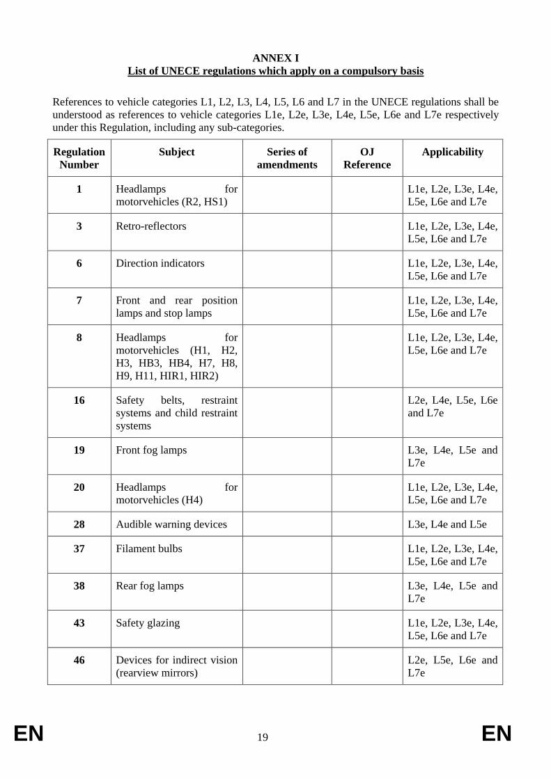
ANNEX I
List of UNECE regulations which apply on a compulsory basis
References to vehicle categories L1, L2, L3, L4, L5, L6 and L7 in the UNECE regulations shall be
understood as references to vehicle categories L1e, L2e, L3e, L4e, L5e, L6e and L7e respectively
under this Regulation, including any sub-categories.
Regulation
Number
Subject Series of
amendments
OJ
Reference
Applicability
1 Headlamps for
motorvehicles (R2, HS1)
L1e, L2e, L3e, L4e,
L5e, L6e and L7e
3 Retro-reflectors L1e, L2e, L3e, L4e,
L5e, L6e and L7e
6 Direction indicators L1e, L2e, L3e, L4e,
L5e, L6e and L7e
7 Front and rear position
lamps and stop lamps
L1e, L2e, L3e, L4e,
L5e, L6e and L7e
8 Headlamps for
motorvehicles (H1, H2,
H3, HB3, HB4, H7, H8,
H9, H11, HIR1, HIR2)
L1e, L2e, L3e, L4e,
L5e, L6e and L7e
16 Safety belts, restraint
systems and child restraint
systems
L2e, L4e, L5e, L6e
and L7e
19 Front fog lamps L3e, L4e, L5e and
L7e
20 Headlamps for
motorvehicles (H4)
L1e, L2e, L3e, L4e,
L5e, L6e and L7e
28 Audible warning devices L3e, L4e and L5e
37 Filament bulbs L1e, L2e, L3e, L4e,
L5e, L6e and L7e
38 Rear fog lamps L3e, L4e, L5e and
L7e
43 Safety glazing L1e, L2e, L3e, L4e,
L5e, L6e and L7e
46 Devices for indirect vision
(rearview mirrors)
L2e, L5e, L6e and
L7e
EN 20 EN
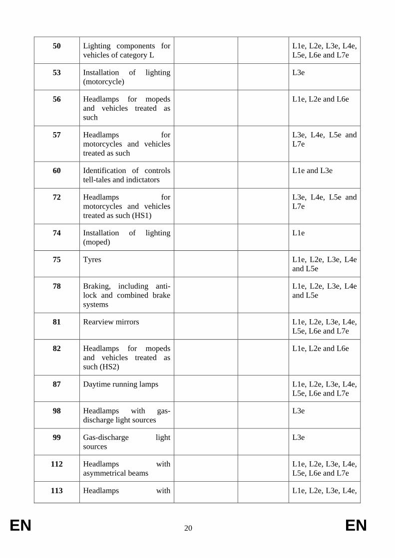
50 Lighting components for
vehicles of category L
L1e, L2e, L3e, L4e,
L5e, L6e and L7e
53 Installation of lighting
(motorcycle)
L3e
56 Headlamps for mopeds
and vehicles treated as
such
L1e, L2e and L6e
57 Headlamps for
motorcycles and vehicles
treated as such
L3e, L4e, L5e and
L7e
60 Identification of controls
tell-tales and indictators
L1e and L3e
72 Headlamps for
motorcycles and vehicles
treated as such (HS1)
L3e, L4e, L5e and
L7e
74 Installation of lighting
(moped)
L1e
75 Tyres L1e, L2e, L3e, L4e
and L5e
78 Braking, including anti-
lock and combined brake
systems
L1e, L2e, L3e, L4e
and L5e
81 Rearview mirrors L1e, L2e, L3e, L4e,
L5e, L6e and L7e
82 Headlamps for mopeds
and vehicles treated as
such (HS2)
L1e, L2e and L6e
87 Daytime running lamps L1e, L2e, L3e, L4e,
L5e, L6e and L7e
98 Headlamps with gas-
discharge light sources
L3e
99 Gas-discharge light
sources
L3e
112 Headlamps with
asymmetrical beams
L1e, L2e, L3e, L4e,
L5e, L6e and L7e
113 Headlamps with L1e, L2e, L3e, L4e,

EN 21 EN
symmetrical beams L5e, L6e and L7e
Explanatory note: The fact that a component is included in this list, does not make its installation
mandatory. For certain components, however, mandatory installation requirements are laid down in
other annexes to this Regulation.
EN 22 EN
ANNEX II
Test procedures and performance requirements on audible warning devices
Part 1 – Requirements applying to the component type-approval of audible warning devices
1. Requirements for audible warning devices intended to be fitted to vehicles of
category L1e, L2e and L6e.
1.1. Audible warning devices shall emit a continuous, uniform sound and their sound
spectrum shall not vary perceptibly during operation. In the case of warning devices
supplied with an alternating current this requirement applies solely at constant
generator speed, that speed lying within the range specified in paragraph 2.3.2.
1.2. Warning devices shall have sound characteristics (spectral distribution of the sound
energy, sound pressure level) and mechanical characteristics such that, in the order
stated, they pass the tests specified in paragraphs 2. to 3.4..
2. Sound level measurements
2.1. Audible warning devices shall preferably be tested in an anechoic environment.
They may alternatively be tested in a semi-anechoic chamber or in a cleared outside
space. In this case, precautions shall be taken in order to avoid reflections off the
ground in the measuring area, e.g. by providing a number of absorbent screens. It
shall be checked that the spherical distortion is no more than 1 dB(A) within a
hemisphere having a radius of at least 5 m up to the maximum frequency to be
measured, this mainly being in the direction of measurement and at the height of the
device and microphone. The ambient noise shall be at least 10 dB(A) lower than the
sound pressure levels to be measured.
The device submitted for testing and the microphone shall be at the same height.
That height shall lie between 1.15 and 1.25 m. The line of maximum sensitivity of
the microphone shall coincide with the direction in which the sound level of the
warning device is at its highest level.
The microphone shall be positioned such that its diaphragm is at a distance of 2 ±
0.01 m from the exit plane of the sound emitted by the device. That same distance
from devices having several exits shall be determined in relation to the exit plane
closest to the microphone.
2.2. The measurements of the sound pressure level shall involve the use of a class-1
precision sound level meter meeting the requirements of IEC publication No 651,
first edition (1979).
All measurements shall be carried out using the ‘rapid’ time constant. The (A)
weighting curve shall be used to measure the overall sound pressure levels.
The Fourier transform of the sound signal shall be used in measuring the emitted-
sound spectrum. Alternatively, third octave filters meeting the requirements set out
in IEC publication No 225, first edition (1966) may be used.
In that instance the sound pressure level within the 2500 Hz centre octave frequency
band is determined by adding the quadratic means of the sound pressures in the
third-octave bands of centre frequencies of 2000, 2500 and 3150 Hz.
In all cases only the Fourier transform method may be considered to be a reference
EN 23 EN
method.
2.3. The audible warning device shall be supplied with one of the following voltages, as
appropriate:
2.3.1. In the case of audible warning devices receiving direct current, a test voltage of 6.5,
13.0 or 26.0 V, measured at the output side of the electricity source and
corresponding to a nominal voltage of 6, 12 or 24 V respectively.
2.3.2. Where audible warning devices receive direct current which has to be supplied by
an electrical generator of the type normally used with this type of device, the
acoustic characteristics of that type of warning device shall be recorded at alternator
speeds corresponding to 50%, 75% and 100% of the maximum speed stated by the
manufacturer of the alternator for continuous operation. The alternator shall be
subject to no other electrical load during the test. The endurance test described in
paragraphs 3. to 3.4 shall be carried out at a speed stated by the manufacturer of the
equipment and selected from the range referred to above.
2.4. If a rectified current is used for the test on an audible warning device receiving
direct current, the unsmoothed component of the voltage at its terminals, measured
from peak to peak during operation of the warning devices, shall not exceed 0.1 V.
2.5. The resistance of the electrical conductor for audible warning devices receiving
direct current, including the resistance of the terminals and contacts, shall lie as
closely as possible to: 0.05 for a nominal voltage of 6 V, 0.10 for a nominal
voltage of 12 V and 0.20 for a nominal voltage of 24 V.
2.6. The audible warning device shall be rigidly mounted, using the part or parts
intended for that purpose by its manufacturer on a support, the mass of which is at
least 10 times greater than that of the warning device to be tested and at least 30 kg.
Moreover, the support shall be arranged in such a way that the reflections off its
walls and the vibrations have no significant effect on the results of the
measurements.
2.7. Under the conditions set out above, the A-weighted sound level shall not exceed
115 dB(A).
2.7.1. Moreover the sound pressure level within the 1800 to 3550 Hz frequency band shall
be higher than that of any frequency component above 3550 Hz, and in any case be
at least 90 dB(A).
2.8. The characteristics set out in paragraphs 2.7. to 2.7.1 shall also be displayed by any
audible warning device that has been subjected to the endurance test provided for in
paragraphs 3. to 3.4. The variation in voltage shall be either between 115 and 95 %
of the rated value for audible warning devices receiving direct current or between
50 and 100 % of the maximum alternator speed stated by the manufacturer of the
alternator for continuous operation in the case of audible warning devices receiving
alternating current.
2.9. The time lag between actuation and the moment when the sound reaches the
minimum value as required in paragraphs 2.7. to 2.7.1 shall not exceed 0.2 seconds
measured at an ambient temperature of 20 ± 5 ºC. This requirement applies, in

EN 24 EN
particular, to pneumatic or electro-pneumatic warning devices.
2.10. Under the power supply conditions laid down by their manufacturers, pneumatic or
electro-pneumatic warning devices shall yield the same acoustic performance as
those required for electric audible warning devices.
2.11. The minimum value as required in paragraphs 2.7. to 2.7.1 shall be obtained for
each of the individual components of any multi-tone device each component part of
which may emit sound independently. The maximum overall sound level shall be
achieved with all of the component parts operating at the same time.
3. Endurance test
3.1. The audible warning device shall be supplied with the nominal voltage at the
conductor resistance specified in paragraphs 2.3. to 2.5. Part 1 and be operated
10000 times at a rate of one second of being activated, followed by four seconds of
not being activated. During the test the audible warning device shall be exposed to a
forced wind or draught with a speed of 10 m/s ± 2 m/s.
3.2. If a test is conducted within an insulated chamber, that chamber shall be of
sufficient volume to ensure normal dissipation of the heat given off by the warning
device during the endurance test.
3.3. The ambient temperature shall lie between 15 and 30 ºC.
3.4. At the time when half of the total number of operations as required has been
completed, the audible warning device may be reset if the characteristics of the
sound level have altered in comparison to before the test. When the total number of
operations as required has been completed, the audible warning device may again
be reset and shall subsequently be subjected to the tests as specified in paragraph
2.8.
Part 2 – Requirements applying to the installation and performance of audible warning devices
1. Fitting requirements
1.1. Vehicles of category L1e, L2e and L6e shall be fitted with at least one audible
warning device which has been component type-approved pursuant to this
Regulation, however, such vehicles may alternatively be fitted with at least one
audible warning device which has been component type-approved pursuant to
UNECE regulation No. 2812
.
1.2. Vehicles of category L1e, developing a power of not more than 0,5 kW and whose
maximum design speed does not exceed 25 km/h, may alternatively be fitted with a
non-approved mechanical audible warning device. In this case, the manufacturer
shall declare that such mechanical audible warning device meets national
requirements in the Member State where the vehicle is to be put into service.
1.3. Vehicles of category L3e, L4e and L5e shall meet all the relevant fitting
12 OJ L 185, 17.7.2010, p. 1.

EN 25 EN
requirements of UNECE regulation No. 28.
1.3.1. In the absence of specific instructions, the term ‘motor cycles’ in that regulation
shall be construed as being vehicles of category L3e, L4e and L5e.
1.4. Vehicles of category L7e shall meet all the relevant fitting requirements of UNECE
regulation No. 28, as prescribed for vehicle category L5e.
2. Performance requirements
2.1. The test voltage shall be as laid down in paragraphs 2.3. to 2.3.2. in Part 1.
2.2. The sound pressure levels shall be measured under the conditions as laid down in
paragraph 2.2. in Part 1.
2.3. The A-weighted sound pressure level emitted by the audible warning device(s)
fitted on the vehicle shall be measured at a distance of 7.0 m in front of the vehicle,
the latter being placed on an open site, on ground as smooth as practicable and, in
the case of audible warning devices supplied with direct current, with its engine
stopped, if fitted.
2.4. The microphone of the measuring instrument shall be placed in the mean
longitudinal plane of the vehicle.
2.5. The sound pressure level of the background noise and wind noise shall be at least
10 dB (A) below the sound to be measured.
2.6. The maximum sound pressure level shall be sought within the range of 0.5 and 1.5
m above the ground.
2.7. When measured under the conditions as specified in paragraphs 2.1. to 2.5. of Part
2, the maximum sound level value as determined in paragraph 2.6. of Part 2 shall be
at least 75 dB(A) and at the most 112 dB(A) for vehicles of category L1e and L2e.
2.8. Vehicles of category L3e, L4e and L5e shall meet all the relevant performance
requirements of UNECE regulation No. 28.
2.8.1. In the absence of specific instructions, the term ‘motor cycles’ in that regulation
shall be construed as being vehicles of category L3e, L4e and L5e.
2.9. Vehicles of category L7e shall meet all the relevant performance requirements of
UNECE regulation No. 28, as prescribed for vehicle category L5e.
EN 26 EN
ANNEX III
Requirements on braking, including anti-lock and combined braking systems
1. Requirements
1.1. Vehicles of category L1e, L2e, L3e, L4e and L5e shall meet all the relevant
requirements of UNECE regulation No. 78.
1.1.1. Vehicles with a maximum vehicle design speed ≤ 25 km/h shall meet all the
relevant requirements of UNECE regulation No. 78, as prescribed for vehicles with
a maximum vehicle design speed > 25 km/h, except for vehicles of category L1e
concerning the points laid down in paragraphs 1.1.1.1. to 1.1.1.4.
1.1.1.1. In braking devices where the transmission is hydraulic, the receptacles containing
the reserve fluid are exempted from the ease of fluid level checking requirements.
1.1.1.2 For rim brakes, as fitted to some of these vehicles and concerning the special
provisions relating to testing with wet brakes, the water shall be directed onto the
part of the wheel rim providing the friction, the nozzles to be positioned 10 to 30
mm to the rear of the brake blocks.
1.1.1.3. For vehicles fitted with wheel rims of 45 mm or less (code 1.75), concerning
stopping distance with the front brake only, in laden condition, the MFDD may be
2.8 or S ≤ 0.1 + V2/73. If this value cannot be achieved by each braking device
because of limited adhesion, the value 4.0 m/s2 shall be applied for a test on a laden
vehicle using both braking devices simultaneously.
1.1.1.4. Concerning performance levels (minimum and maximum) to be attained with wet
brake(s), the mean deceleration to be attained between 0.5 and 1.0 second after
application of the brake shall be at least 40 % of that attained with dry brake(s)
when the same control force is applied.
1.1.2. The requirements of Annex VIII to Regulation (EU) No [xxx/2013] on the
mandatory fitting of advanced brake systems shall be complied with.
1.2. Vehicles of category L6e shall meet all the relevant requirements of UNECE
regulation No. 78 laid down for vehicle category L2e.
1.3. Vehicles of category L7e shall meet all the relevant requirements of UNECE
regulation No. 78, as prescribed for vehicle category L5e.

EN 27 EN
ANNEX IV
Requirements on electrical safety
1. Requirements
1.1. All vehicles categories shall meet all the relevant requirements of UNECE
regulation No. 100.
EN 28 EN
ANNEX V
Requirements on manufacturer declaration requirements regarding endurance testing of
functional safety critical systems, parts and equipment
1. Requirements
1.1. The vehicle manufacturer shall provide a statement in conformity with Article 22
(2) and Annex VIII of Regulation (EU) No [xxx/2013] and based on the template to
be adopted by the Commission in accordance with Article 22(7) of that Regulation.
Vehicles and their systems, parts and equipment critical for functional safety shall
be able to withstand normal use as intended , throughout the normal life of the
vehicle, if used under normal conditions and serviced in accordance with the
manufacturer's recommendations taking into account regular and scheduled
maintenance and specific equipment adjustments, which are foreseen as per the
clear and unambiguous instructions provided by the vehicle manufacturer in the
instruction manual as provided with the vehicle.
1.2. Type-approved tyres and replaceable light sources of lighting components are
excluded from the endurance requirements.
1.3. The vehicle manufacturer is not obliged to surrender information such as a file
containing proprietary information pertaining to company data concerning
endurance testing procedures and other related internal practises.
1.4. ] The manufacturers statement is without prejudice to the warranty obligations
versus the owner of the vehicle.
EN 29 EN
ANNEX VI
Requirements on front and rear protective structures
1. Requirements
1.1. If the requirements as set out in UNECE regulation No. 26, concerning the external
projections, have been applied to the entire vehicle, as required by Commission
Delegated Regulation (EU) No …/2012 of […] on the vehicle construction
requirements for the approval of two- or three-wheel vehicles and quadricycles, the
requirements as set out in this Annex do not apply.
1.2. If the requirements as set out in UNECE regulation No. 26, concerning the external
projections, have not or have only been partly applied to the vehicle, as permitted in
accordance with Commission Delegated Regulation (EU) No …/2012 of […] on the
vehicle construction requirements for the approval of two- or three-wheel vehicles
and quadricycles, the following requirements shall be met.
1.2.1. Vehicles, whose relevant front structure has been completely assessed in
accordance with UNECE regulation No. 26, are deemed to comply with the
requirements on front protective structures.
1.2.2. Vehicles which have a single front wheel and whose external projections forward of
the front axle have been assessed by means of the testing device as prescribed and
in conformity with Commission Delegated Regulation (EU) No …/2012 of […] on
the vehicle construction requirements for the approval of two- or three-wheel
vehicles and quadricycles are deemed to comply with the requirements on front
protective structures.
1.2.3. Vehicles, which have more than one front wheel and whose relevant front structure
has not been completely assessed in accordance with UNECE regulation No. 26,
shall meet the following requirements.
1.2.3.1. The tyres of the vehicle’s front wheels, as considered in the straight forward
position, shall not form the foremost point or points of the overall vehicle.
1.2.3.2. At least two thirds of the width of the vehicle as measured at the location of the
front axle, shall consist of vehicle structure forward of the transverse line which is
halfway between the front axle and the foremost point of the vehicle (i.e. the
relevant structure). The location in terms of height of this structure is relevant only
above the floor line and below 2.0 m.
1.2.3.3. None of the structure forward of the line as described in paragraph 1.2.3.2. shall
have pointed or sharp parts or projections which are directed outwards and which
are likely to catch on or significantly increase the severity of injuries or chance of
lacerations to vulnerable road users in case of a collision, while driving forward.
The structure shall in any case exhibit no edges which can be contacted by a 100
mm sphere and which have a radius of curvature of less than 2.5 mm. Edges may
however be blunted where their projection is less than 5.0 mm and there are no
specific requirements for edges whose projection is less than 1.5 mm.
1.2.4. Vehicles which are not equipped with a device for reversing are exempted from the
requirements on rear protective structures as laid down in paragraphs 1.2.5. to

EN 30 EN
1.2.5.2.
1.2.5. Vehicles which are equipped with a device for reversing and whose relevant rear
structure has been completely assessed in accordance with UNECE regulation No.
26, are deemed to comply with the requirements on rear protective structures.
1.2.6. Vehicles which are equipped with a device for reversing and whose relevant rear
vehicle structure has not been completely assessed in accordance with UNECE
regulation No. 26 and which are equipped with a device for reversing, shall meet
the following requirements.
1.2.6.1. At least two thirds of the width of the vehicle as measured at the rear axle shall
consist of vehicle structure. The location in terms of height of this structure is
relevant only above the floor line and below 2.0 m.
1.2.6.2. None of the structure rearward of the rear axle shall have pointed or sharp parts or
projections which are directed outwards and which are likely to catch on or
significantly increase the severity of injuries or chance of lacerations to vulnerable
road users in case of a collision, while driving rearward. The structure shall in any
case exhibit no edges which can be contacted by a 100 mm sphere and which have a
radius of curvature of less than 2.5 mm. Edges may however be blunted where their
projection is less than 5.0 mm and there are no specific requirements for edges
whose projection is less than 1.5 mm.
1.3. If the material hardness is measured upon request of the technical service, the
hardness measurement shall be taken with the material as installed on the vehicle.
Where it is impossible to carry out such a measurement correctly, the technical
service may accept alternative assessment methods.

EN 31 EN
ANNEX VII
Requirements on glazing, windscreen wipers and washers, and defrosting and demisting
systems
Part 1 – Requirements applying to glazing
1. Fitting requirements.
1.1. Vehicles shall only be fitted with safety glazing.
1.1.1. All safety glazing fitted to the vehicle shall be type-approved in accordance with
UNECE regulation No. 43.
1.1.2. Safety glazing shall be fitted in such a way that, despite the stresses to which the
vehicle is submitted under normal operating conditions, it remains in position and
continues to afford visibility and safety to the occupants or riders of the vehicle.
1.1.3. Plastic windscreens which are fitted to vehicles without bodywork and which are
not supported at the top are not deemed to be safety glazing and are exempted from
the requirements as laid down in this Annex.
1.1.3.1. Further to definition (4) in Article 2 of this Regulation and for the purpose of this
Annex, a vehicle is deemed to have bodywork if there are structural elements such
as A-pillars or a rigid frame around the windscreen, in combination with other
possible elements such as side doors, side windows and/or a roof creating an
enclosed or partly enclosed compartment and the technical service shall clearly
justify the judgment criteria in the test report.
2. Specific provisions
2.1. Vehicles of category L shall meet all the relevant requirements as set out in Annex
21 of UNECE regulation No. 43, as prescribed for vehicle category M1.
2.1.1. Paragraph 4.3.1. of Annex 21 of UNECE regulation No. 43 is not applicable for
vehicles of category L1e, L2e, L3e, L4e and L5e. In addition, plastic safety glazing,
provided that it is type-approved, may be fitted as a windscreen on vehicles of these
categories.
Part 2 – Requirements applying to windscreen wipers and washers
1. Fitting requirements
1.1. Every vehicle, which is fitted with a windscreen made from safety glazing, shall be
equipped with a windscreen wiper system which is able to function when the
vehicle master control switch has been activated, without any action by the driver
other than switching the operating control, needed for starting and stopping the
windscreen wiper system, to the on position.
1.1.1. The windscreen wiper system shall consist of one or more wiper arms which shall
have wiper blades that are easily replaceable and which can be cleaned manually.
Wiper arms shall be fitted in such a way that they can be folded away from the
windscreen.

EN 32 EN
1.1.2. The windscreen wiper field shall cover at least 90% of vision area A, as determined
in accordance with Appendix 1 of Part 2.
1.1.2.1. The windscreen wiper field shall meet the requirements when the system is
operating at a sweep frequency corresponding to paragraph 1.1.3. below. The
windscreen wiper field shall be assessed under the conditions as set out in
paragraphs 2.1.10. to 2.1.10.3. of part 2.
1.1.3. The windscreen wiper shall have a sweep frequency of at least 40 cycles per minute
and this frequency shall be attained under the conditions as specified in paragraphs
2.1.1. to 2.1.6 and 2.1.8. of Part 2
1.1.4. The windscreen wiper system shall be capable of operating for two minutes on a dry
windscreen without degradation of performance.
1.1.4.1. The performance of the windscreen wiper system on a dry windscreen shall be
tested under the conditions as set out in paragraph 2.1.11. of Part 2.
1.1.5. The windscreen wiper system shall be capable of withstanding stalling for at least
15 seconds. The use of automatic circuit protection devices is allowed, provided
that for possible resetting no action is required other than operation of the
windscreen wiper operating control.
1.1.5.1. The capability to withstand stalling of the windscreen wiper system shall be tested
under the conditions as set out in paragraph 2.1.7. of Part 2
1.2. Every vehicle, which is fitted with a windscreen made from safety glazing, shall be
fitted with a windscreen washer system which is able to function when the vehicle
master control switch has been activated, and which is capable of withstanding the
loads and pressures resulting when the nozzles are plugged and the system is
actuated in accordance with the procedure set out in paragraphs 2.2.1.1. to 2.2.1.1.2.
of Part 2.
1.2.1. The performance of the windscreen washer system shall not be adversely affected
by exposure to the temperature cycles in accordance with paragraphs 2.2.1. to
2.2.3.1. of Part 2.
1.2.2. The windscreen washer system shall have the ability to spray fluid onto the target
area of the windscreen, without any trace of leakage, disconnection of any tubing
and malfunctioning of any nozzle, at normal conditions when subjected to ambient
temperatures between -18ºC and 60ºC. In addition, when the nozzles are blocked,
the system shall also show no signs of leakage and disconnection of any tubing.
1.2.3. The windscreen washer system shall be capable of delivering sufficient fluid to
clear at least 60% of vision area A, as determined in accordance with Appendix 1 of
Part 2, under the conditions as set out in paragraphs 2.2.5. to 2.2.5.4. of Part 2.
1.2.4. The windscreen washer system shall be capable of being manually activated by
means of the washer control. In addition, activation and deactivation of the system
may also be coordinated and combined with any other vehicle system.
EN 33 EN
1.2.5. The capacity of the reservoir containing the liquid shall not be less than 1.0 litre.
1.2.6. A windscreen washer system which has been approved as a separate technical unit
in accordance with Commission Regulation (EU) No 1008/201013
may be installed,
provided that the provisions of paragraph 2.2.6. of Part 2 are met.
2. Test procedure
2.1. Windscreen wiper system test conditions.
2.1.1. The tests described below shall be carried out under the conditions as stated in
paragraphs 2.1.2. to 2.1.5. of Part 2 unless specified otherwise.
2.1.2. The ambient temperature shall be between 5°C and 40°C.
2.1.3 The windscreen shall be kept constantly wet.
2.1.4. In the case of an electric windscreen wiper system, the following additional
conditions shall be met.
2.1.4.1. All batteries shall be fully charged at the start of the test.
2.1.4.2. The engine, if fitted, shall run at a speed not exceeding 30% of the speed
corresponding to its maximum power output. However, if this is proven not to be
practicable due to specific engine control strategies, for instance in the case of
electric hybrid vehicles, a realistic scenario taking into account the engine speeds,
periodical absence or complete absence of a running engine during normal driving
conditions, shall be determined. If the windscreen wiper system can meet the
requirements without a running engine, the engine does not have to run at all.
2.1.4.3. The passing beam headlamps shall be switched on.
2.1.4.4. All fitted heating, ventilation, defrosting and demisting systems (regardless of the
location in the vehicle) shall be operating at maximum electrical consumption.
2.1.5. Compressed air or vacuum operated windscreen wiper systems shall be able to
function continuously at the prescribed sweep frequencies whatever the engine
speed and engine load or minimum and maximum battery charge levels specified by
the manufacturer for normal operation.
2.1.6. The sweep frequency of the windscreen wiper system shall comply with the
requirements of paragraph 1.1.3. of Part 2 after a preliminary operating time of 20
minutes on a wet windshield.
2.1.7. The requirements of paragraph 1.1.5. of Part 2 shall be satisfied when the wiper
arms are restrained in a position corresponding to half a cycle, for a period of 15
seconds with the windscreen wiper control set at the maximum sweep frequency.
2.1.8. The outer face of the windscreen shall be thoroughly degreased by means of
13 OJ L 292, 10.11.2010, p. 2
EN 34 EN
methylated spirit or an equivalent degreasing agent. After drying, a solution of
ammonia of not less than 3 % and not more than 10 % shall be applied. The surface
shall be allowed to dry again and shall then be wiped with a dry cotton cloth.
2.1.9. A coating of the test mixture, in accordance with the specifications as laid down in
Appendix 2 of Part 2, shall be applied uniformly to the outer surface of the
windscreen and allowed to dry.
2.1.9.1. Where the outer face of the windscreen has been prepared in accordance with
paragraphs 2.1.8. and 2.1.9., the windscreen washer system may be used during the
applicable tests.
2.1.10. The wiper field of the windscreen wiper system, as prescribed in paragraph 1.1.2. of
Part 2, shall be determined as follows.
2.1.10.1. The outer face of the windscreen shall be treated in accordance with paragraphs
2.1.8. and 2.1.9.
2.1.10.2. In order to verify that the requirements of paragraph 1.1.2. of Part 2 are met, the
windscreen wiper system shall be activated, taking into account paragraph 2.1.9.1.,
and a trace of the wiper field shall be made and compared to a trace of the vision
area A, as determined in accordance with Appendix 1 of Part 2.
2.1.10.3. The technical service may agree to an alternative test procedure (e.g. virtual testing)
to verify that the requirements of paragraph 1.1.2. of Part 2 are met.
2.1.11. The requirements of paragraph 1.1.4. of Part 2 shall be satisfied under the
conditions of paragraph 2.1.2. The vehicle shall be prepared to operate under the
conditions as set out in paragraphs 2.1.4. to 2.1.5. During the test, the wiper system
shall be operating normally, but at the maximum sweep frequency. The wiper field
does not have to be observed.
2.2. Windscreen washer system test conditions.
2.2.1. Test No. 1. The windscreen washer system shall be filled with water, fully primed,
and placed in an ambient temperature of 20 ± 2°C for a minimum of four hours. The
water shall be stabilized at this temperature.
2.2.1.1. All nozzle outlets shall be plugged and the windscreen washer control shall be
actuated six times in one minute, each time for at least three seconds.
2.2.1.1.1 If the windscreen washer system is powered by the muscular energy of the driver,
the force applied shall be 11.0 to 13.5 daN in case of a hand operated pump. The
force applied shall be 40.0 to 44.5 daN in case of a foot operated pump.
2.2.1.1.2. In case of electric pumps, the test voltage shall not be less than the rated voltage and
not more than the rated voltage plus 2 Volt.
2.2.1.2. The performance of the windscreen washer system at the end of the test shall be in
compliance with paragraph 1.2.2. of Part 2.
2.2.2. Test No. 2. The windscreen washer system shall be filled with water, fully primed,
EN 35 EN
and placed in an ambient temperature of -18 ± 3°C for a minimum of four hours,
ensuring that all the water contained in the device is frozen. The device is then
exposed to an ambient temperature of 20 ± 2 oC until the ice has completely melted.
2.2.2.1. The performance of the windscreen washer system shall then be verified by
actuating the system in accordance with paragraphs 2.2.1.1. to 2.2.1.2.
2.2.3. Test No. 3. The windscreen washer system shall be filled with water of a
temperature of 60° ± 3°C.
2.2.3.1. The performance of the windscreen washer system shall then be verified by
actuating the system in accordance with paragraphs 2.2.1.1. to 2.2.1.2.
2.2.4. The windscreen washer system tests as set out in paragraphs 2.2.1. to 2.2.3.1. shall
be carried out in sequence on the same windscreen washer system. The system may
be either tested as installed on the vehicle type for which EC type-approval is
sought, or separately.
2.2.5. Test No. 4. Windscreen washer system capability test
2.2.5.1. The windscreen washer system shall be filled with water and fully primed. With the
vehicle stationary and no significant wind effect, the nozzle(s) may, if possible, be
adjusted as to being pointed towards the target area on the outer face of the
windscreen.
2.2.5.2. The outer face of the windscreen shall be treated as prescribed in paragraphs 2.1.8
and 2.1.9.
2.2.5.3. The windscreen washer system shall be actuated according to the manufacturer’s
instructions, taking into account paragraphs 2.2.1.1.1 and 2.2.1.1.2. The total
duration of the test shall not exceed 10 complete cycles of automatic operation of
the windscreen wiper system operating at the maximum sweep frequency.
2.2.5.4. In order to verify that the requirements of paragraph 1.2.3. of Part 2 are met, a trace
of the relevant cleaned area shall be made and compared to a trace of the vision area
A, as determined in accordance with Appendix 1 of Part 2. If it is clearly obvious to
the observer that the requirements are met, it is not required that the traces are
prepared.
2.2.6. Only the test as set out in paragraphs 2.2.5. to 2.2.5.4. needs to be performed
concerning the windscreen washer system in case a type-approved separate
technical unit is installed on the vehicle, in accordance with paragraph 1.2.6. of Part
2.
Part 2 – Appendix 1 – Procedure for determining vision areas on windscreens of vehicles
The vision area A is established in accordance with the provisions laid down in
Annex 18 of UNECE regulation 43.
Part 2 – Appendix 2 – Specifications of the test mixture for testing the windscreen wiper and
washer systems
EN 36 EN
The test mixture referred to in paragraph 2.1.9. of Part 2 shall be in accordance with
the provisions laid down in Appendix 4 to Annex III of Commission Regulation
(EU) No 1008/2010.
Part 2 – Appendix 3 – Procedure for verification of the R-point or seating reference point
The R-point or seating reference point is established in accordance with the
provisions laid down in Annex 3 to UNECE regulation No 1714
Part 2 – Appendix 4 – Procedure for determining primary reference marks in the three-dimensional
reference system
The dimensional relationships between primary reference marks on drawings and
their position on the actual vehicle are established in accordance with the provisions
laid down in Annex 4 to UNECE regulation No 12515
.
Part 3 – Requirements applying to defrosting and demisting systems
1. Fitting requirements
1.1. Every vehicle, except those of category L2e, fitted with a windscreen made from
safety glazing, shall be equipped with a system for removing frost and ice from the
exterior glazed surface of the windscreen system and for removing mist from the
interior glazed surface of the windscreen. The windscreen defrosting and demisting
system shall be effective enough to ensure adequate visibility through the
windscreen in cold weather.
1.1.1. Vehicles with a maximum power not exceeding 15 kW shall meet all the relevant
requirements of UNECE regulation No. 12216
, as prescribed for vehicle category
M1.
1.1.2. Vehicles with a maximum power exceeding 15 kW shall meet all the relevant
requirements of Commission Regulation (EU) No 672/201017
, as prescribed for
vehicle category M1.
1.2. However, if the windscreen is fitted in such a way that there is not any vehicle
structure attached to the windscreen extending rearwards for more than 100 mm,
taking into account that any detachable or retractable door or roof is installed and in
the closed position, the defrosting and demisting system is not required.
14 OJ L 373, 27.12.2006, p. 1. 15 OJ L 200, 31.7.2010, p. 38. 16 UN regulation 122 first reference 17 OJ L 196, 28.7.2010, p. 5
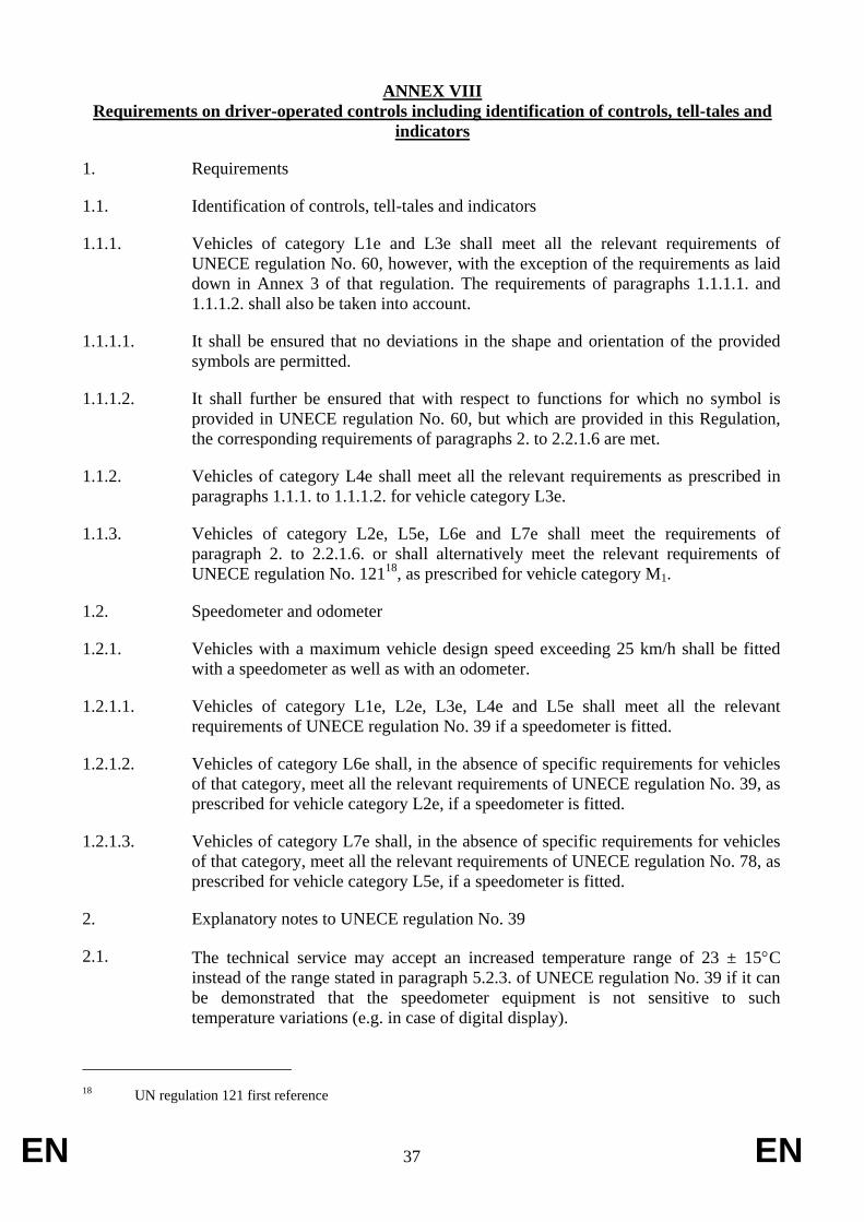
EN 37 EN
ANNEX VIII
Requirements on driver-operated controls including identification of controls, tell-tales and
indicators
1. Requirements
1.1. Identification of controls, tell-tales and indicators
1.1.1. Vehicles of category L1e and L3e shall meet all the relevant requirements of
UNECE regulation No. 60, however, with the exception of the requirements as laid
down in Annex 3 of that regulation. The requirements of paragraphs 1.1.1.1. and
1.1.1.2. shall also be taken into account.
1.1.1.1. It shall be ensured that no deviations in the shape and orientation of the provided
symbols are permitted.
1.1.1.2. It shall further be ensured that with respect to functions for which no symbol is
provided in UNECE regulation No. 60, but which are provided in this Regulation,
the corresponding requirements of paragraphs 2. to 2.2.1.6 are met.
1.1.2. Vehicles of category L4e shall meet all the relevant requirements as prescribed in
paragraphs 1.1.1. to 1.1.1.2. for vehicle category L3e.
1.1.3. Vehicles of category L2e, L5e, L6e and L7e shall meet the requirements of
paragraph 2. to 2.2.1.6. or shall alternatively meet the relevant requirements of
UNECE regulation No. 12118
, as prescribed for vehicle category M1.
1.2. Speedometer and odometer
1.2.1. Vehicles with a maximum vehicle design speed exceeding 25 km/h shall be fitted
with a speedometer as well as with an odometer.
1.2.1.1. Vehicles of category L1e, L2e, L3e, L4e and L5e shall meet all the relevant
requirements of UNECE regulation No. 39 if a speedometer is fitted.
1.2.1.2. Vehicles of category L6e shall, in the absence of specific requirements for vehicles
of that category, meet all the relevant requirements of UNECE regulation No. 39, as
prescribed for vehicle category L2e, if a speedometer is fitted.
1.2.1.3. Vehicles of category L7e shall, in the absence of specific requirements for vehicles
of that category, meet all the relevant requirements of UNECE regulation No. 78, as
prescribed for vehicle category L5e, if a speedometer is fitted.
2. Explanatory notes to UNECE regulation No. 39
2.1. The technical service may accept an increased temperature range of 23 ± 15C
instead of the range stated in paragraph 5.2.3. of UNECE regulation No. 39 if it can
be demonstrated that the speedometer equipment is not sensitive to such
temperature variations (e.g. in case of digital display).
18 UN regulation 121 first reference

EN 38 EN
2. Specific requirements
2.1. Controls, tell-tales and indicators, which are fitted to the vehicle and listed in
paragraph 2.1.10., shall conform to the requirements concerning location,
identification, colour, and illumination of such control, tell-tale or indicator. For
functions for which no symbol is provided in this Regulation, the manufacturer may
use a symbol following the appropriate ISO 6727 or 2575 standards. Where no ISO
symbol is available, the manufacturer may use a symbol of its own conception. In
any case, such symbol shall not cause confusion with any prescribed symbol.
2.1.1. The symbols shall stand out clearly against the background.
2.1.1.1. Contrasting colours shall be used to comply with the requirements of paragraph
2.1.1.
2.1.2. The symbols shall be placed on the control or control tell-tale to be identified or in
immediate proximity thereof. Where this is not possible, the symbol and control or
tell-tale shall be joined by a continuous dash that is as short as possible.
2.1.3. Deviations in the shape of the provided symbols are not permitted.
2.1.4. If necessary for clarity, supplementary symbols may be used in conjunction with
any symbol as specified, however, each additional or supplementary symbol shall
not cause confusion with any symbol specified in this Regulation.
2.1.5. At the manufacturer’s discretion any control or indicator as well as their
identifications may be capable of being illuminated at any time.
2.1.6. A tell-tale shall not emit light except when identifying the malfunction or vehicle
condition for whose indication it is designed or during a functional check (e.g. bulb
check).
2.1.7. Means shall be provided in order to ensure that tell-tales and their identification are
visible and recognisable under all driving conditions.
2.1.7.1. A tell-tale as well as its associated identifying symbol shall be perfectly visible and
recognisable under all ambient lighting conditions when illuminated.
2.1.8. When used for optical tell-tales the following colours listed below shall have the
meanings indicated:
- red: danger to persons or very serious damage to equipment is immediate or
imminent;
- yellow: outside normal operating limits, vehicle system malfunction, damage to
vehicle likely, or other condition which may produce hazard in the longer term
caution;
- green: safety, normal operating condition (except if blue or yellow is required)
The mandatory colours are given in paragraph 2.1.10. It shall be verified that no
inappropriate colour is used for tell-tales even if fitted cumulatively (e.g. red for
normal cruise control operation or for ‘sport’ mode).
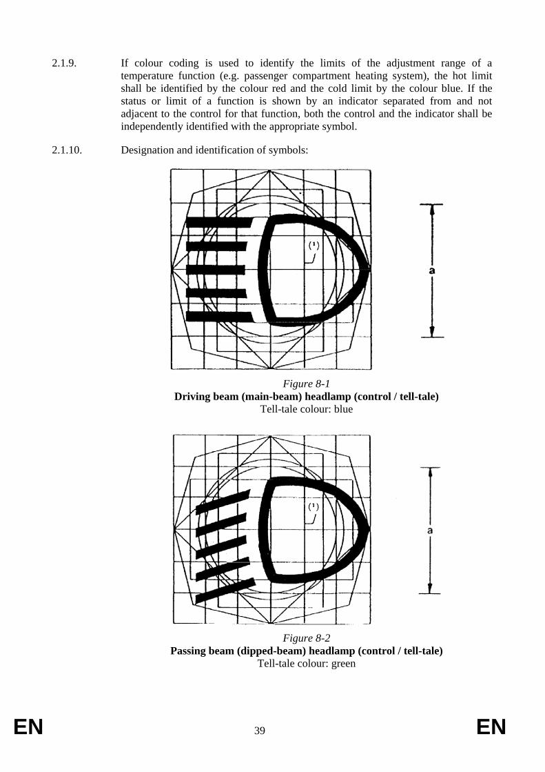
EN 39 EN
2.1.9. If colour coding is used to identify the limits of the adjustment range of a
temperature function (e.g. passenger compartment heating system), the hot limit
shall be identified by the colour red and the cold limit by the colour blue. If the
status or limit of a function is shown by an indicator separated from and not
adjacent to the control for that function, both the control and the indicator shall be
independently identified with the appropriate symbol.
2.1.10. Designation and identification of symbols:
Figure 8-1
Driving beam (main-beam) headlamp (control / tell-tale)
Tell-tale colour: blue
Figure 8-2
Passing beam (dipped-beam) headlamp (control / tell-tale)
Tell-tale colour: green

EN 40 EN
Figure 8-3
Direction indicator (control / tell-tale)
Tell-tale colour: green
Note: if there are separate tell-tales for the left and right direction indicators, the two
arrows may also be used independently.
Figure 8-4
Hazard warning signal (control / tell-tale)
Two possibilities:
- Identifying signal (Figure 8-4),
Tell-tale colour: red
or
- Simultaneous operation of the separate direction indicator tell-tales (Figure 8-3)
provided that these normally operate independently (see Note below Figure 8-3).

EN 41 EN
Figure 8-5
Manual choke (control / tell-tale)
Tell-tale colour: yellow.
Figure 8-6
Audible warning device (control)
Note: if more than one symbol is provided on the control(s), the supplementary
symbol(s) may be mirrored. If the control is located directly on a steering wheel, the
requirements of paragraph 2.1.1.1. do not apply.

EN 42 EN
Figure 8-7
Fuel level (indicator / tell-tale)
Tell-tale colour: yellow
Figure 8-8
Engine coolant temperature (indicator / tell-tale)
Tell-tale colour: red
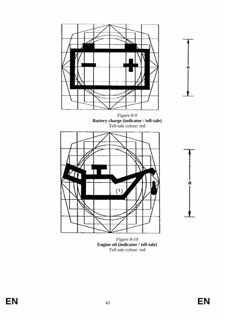
EN 43 EN
Figure 8-9
Battery charge (indicator / tell-tale)
Tell-tale colour: red
Figure 8-10
Engine oil (indicator / tell-tale)
Tell-tale colour: red

EN 44 EN
Figure 8-11
Front fog lamp (control / tell-tale)
Tell-tale colour: green
Figure 8-12
Rear fog lamp (control / tell-tale)
Tell-tale colour: yellow
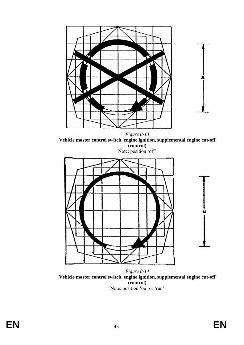
EN 45 EN
Figure 8-13
Vehicle master control switch, engine ignition, supplemental engine cut-off
(control)
Note: position ‘off’
Figure 8-14
Vehicle master control switch, engine ignition, supplemental engine cut-off
(control)
Note: position ‘on’ or ‘run’
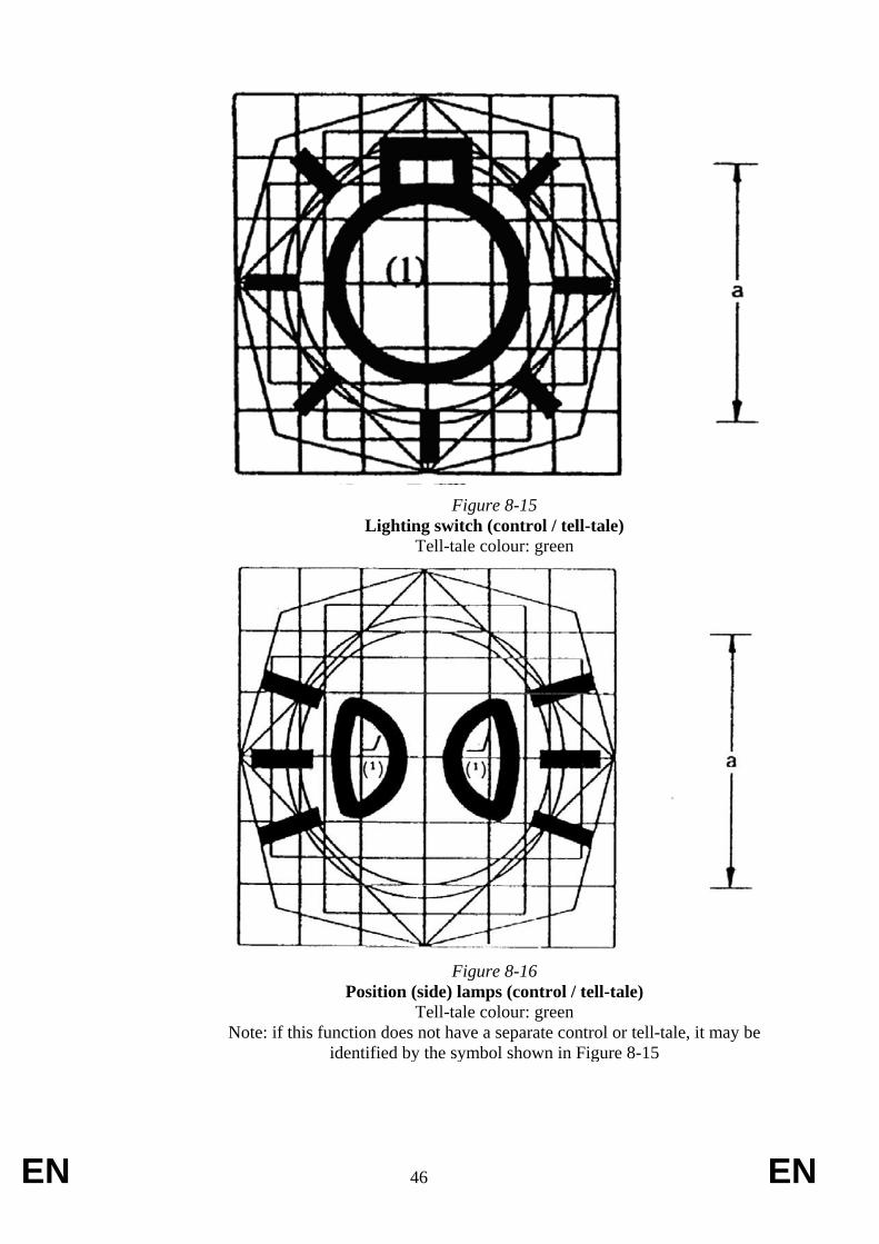
EN 46 EN
Figure 8-15
Lighting switch (control / tell-tale)
Tell-tale colour: green
Figure 8-16
Position (side) lamps (control / tell-tale)
Tell-tale colour: green
Note: if this function does not have a separate control or tell-tale, it may be
identified by the symbol shown in Figure 8-15
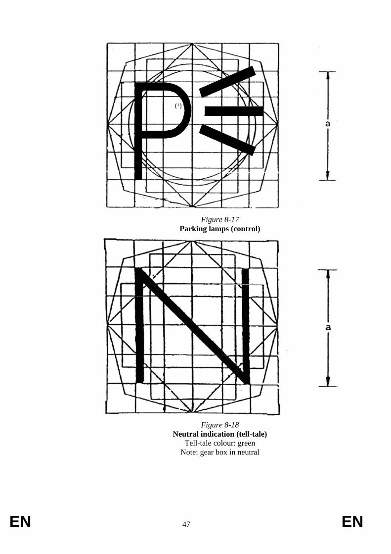
EN 47 EN
Figure 8-17
Parking lamps (control)
Figure 8-18
Neutral indication (tell-tale)
Tell-tale colour: green
Note: gear box in neutral
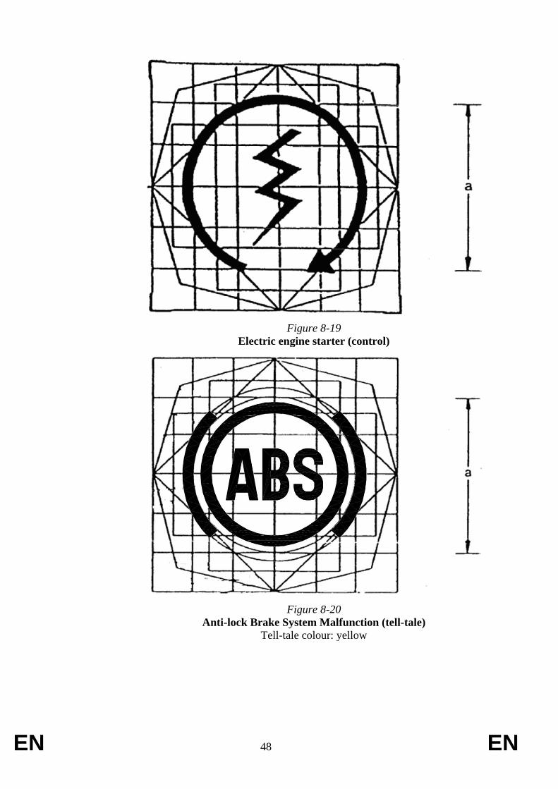
EN 48 EN
Figure 8-19
Electric engine starter (control)
Figure 8-20
Anti-lock Brake System Malfunction (tell-tale)
Tell-tale colour: yellow
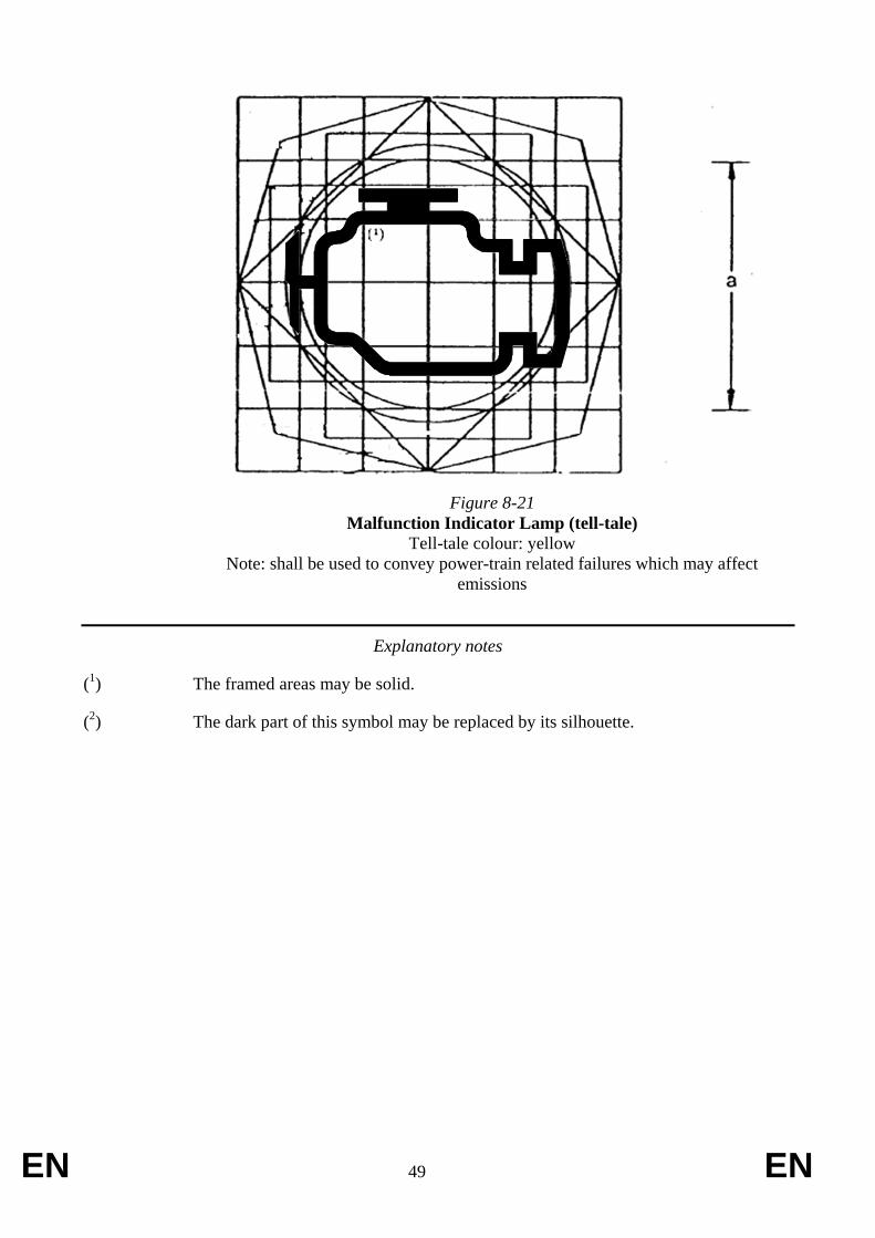
EN 49 EN
Figure 8-21
Malfunction Indicator Lamp (tell-tale)
Tell-tale colour: yellow
Note: shall be used to convey power-train related failures which may affect
emissions
Explanatory notes
(1) The framed areas may be solid.
(2) The dark part of this symbol may be replaced by its silhouette.
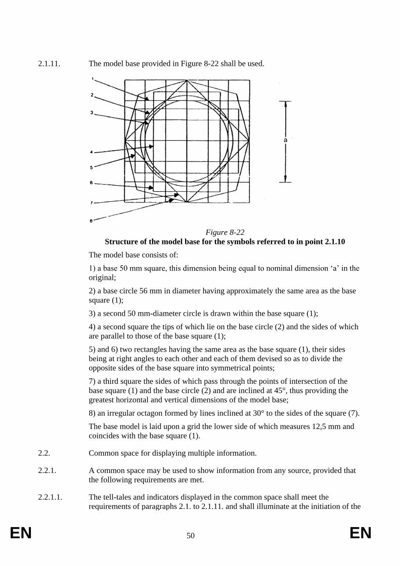
EN 50 EN
2.1.11. The model base provided in Figure 8-22 shall be used.
Figure 8-22
Structure of the model base for the symbols referred to in point 2.1.10
The model base consists of:
1) a base 50 mm square, this dimension being equal to nominal dimension ‘a’ in the
original;
2) a base circle 56 mm in diameter having approximately the same area as the base
square (1);
3) a second 50 mm-diameter circle is drawn within the base square (1);
4) a second square the tips of which lie on the base circle (2) and the sides of which
are parallel to those of the base square (1);
5) and 6) two rectangles having the same area as the base square (1), their sides
being at right angles to each other and each of them devised so as to divide the
opposite sides of the base square into symmetrical points;
7) a third square the sides of which pass through the points of intersection of the
base square (1) and the base circle (2) and are inclined at 45°, thus providing the
greatest horizontal and vertical dimensions of the model base;
8) an irregular octagon formed by lines inclined at 30° to the sides of the square (7).
The base model is laid upon a grid the lower side of which measures 12,5 mm and
coincides with the base square (1).
2.2. Common space for displaying multiple information.
2.2.1. A common space may be used to show information from any source, provided that
the following requirements are met.
2.2.1.1. The tell-tales and indicators displayed in the common space shall meet the
requirements of paragraphs 2.1. to 2.1.11. and shall illuminate at the initiation of the

EN 51 EN
condition they are designed to identify.
2.2.1.2. The tell-tales and indicators that are listed in paragraph 2.1.10. and which are shown
in the common space shall illuminate at the initiation of any underlying condition.
2.2.1.3. Except as provided in paragraphs 2.2.1.4. to 2.2.1.6., when the condition exists for
actuation of two or more tell-tales, the information shall be either:
- repeated automatically in sequence;
or
- indicated by visible means and capable of being selected for viewing by the driver
when seated in the driving position.
2.2.1.4. The tell-tales for any braking system malfunction, headlamp driving beam and
direction indicator shall not be shown in the same common space.
2.2.1.5. If condition of activation exists for one of the following tell-tales: any braking
system malfunction, headlamp driving beam or direction indicator while being
displayed on a common space with other tell-tales, the braking system malfunction,
headlamp driving beam or direction indicator tell-tale shall have priority over
anything else in the common space.
2.2.1.6. Information displayed in the common space may be cancellable automatically or by
the driver, except in case of the tell-tales for any braking system malfunction,
headlamp driving beam and direction indicator as well as any other tell-tale whose
colour is red, when the condition for their activation still exists.
EN 52 EN
ANNEX IX
Requirements on installation of lighting and light signalling devices, including automatic
switching of lighting
1. Requirements
1.1. Vehicles of category L1e shall meet all the relevant requirements of UNECE
regulation No. 74.
1.1.1. Vehicles of category L1e shall, in the absence of specific requirements for vehicles
of that category, be fitted with a rear registration plate lamp.
1.1.2. Vehicles of category L1e-A shall be fitted with a headlamp emitting white light, a
rear position lamp emitting red light, amber side retro-reflectors, amber pedal retro-
reflectors and a red rear retro-reflector. These lighting devices need not to be type-
approved and no other specific fitting requirements apply. In such cases, the
manufacturer shall declare that the lighting devices concerned conform to ISO
standard 6724-1 or ISO standard 6742-2. Vehicles may optionally be fitted with
lighting devices meeting the relevant requirements of UNECE regulation No. 74, as
prescribed for vehicle category L1e.
1.2. Vehicles of category L2e shall meet the requirements of paragraph 2. to 2.4.
1.3. Vehicles of category L3e shall meet all the relevant requirements of UNECE
regulation No. 53.
1.4. Vehicles of category L4e shall meet the requirements of paragraph 3. to 3.2.7.1.
1.5. Vehicles of category L5e shall meet the requirements of paragraph 2. to 2.4.
1.6. Vehicles of category L6e shall meet the requirements of paragraph 2. to 2.4.
1.7. Vehicles of category L7e shall meet the requirements of paragraph 2. to 2.4.
1.8. Vehicles of category L1e and L3e may be fitted with retroflecive or equivalent (e.g.
glowing) devices incorporated in the tyre sidewalls or rims as to provide a visual
impression of circles of light and giving an easy recognition of a two-wheeled
vehicle. Such devices need not to be type-approved as long as they have a similar
performance as required by for instance UNECE regulation No 88 and they may
incorporate small electric light sources with a limited output provided that such light
is not visible directly (i.e. pointed inward to wheel).
1.9. Vehicles of category L1e and L3e may be fitted with additional rear and side retro-
reflective devices and materials provided that they do not impair the effectiveness of
the mandatory lighting and light-signalling devices. In particular luggage
compartments and saddle bags may be fitted with retro-reflective materials,
provided that these have the same colour as the actual lighting device at that
location.
2. Requirements concerning vehicles of category L2e, L5e, L6e and L7e.
2.1. General specifications
EN 53 EN
2.1.1. All lighting devices shall be type-approved and fitted in accordance with the
component manufacturer’s specifications and so installed that under normal
conditions of use and notwithstanding any vibration to which they may be subjected,
they retain the characteristics as prescribed and enable the vehicle to comply with
the requirements of this Annex. In particular, it shall not be possible that the lighting
devices are inadvertently maladjusted.
2.1.2. The illuminating lamps shall be so fitted that their alignment can easily be set
correctly.
2.1.3. The reference axis of the lighting device when fitted to the vehicle shall be
perpendicular to the longitudinal median plane of the vehicle in the case of side
retro-reflectors and parallel to that plane in the case of all other lighting devices,
with a permitted tolerance of 3°.
2.1.4. The height and alignment of lighting devices are verified with the vehicle placed on
a flat horizontal surface in the unladen condition, with the steered wheel(s) in the
straight ahead position and the tyre pressures adjusted to the manufacturer’s
specified values.
2.1.5. In the absence of specific requirements, lighting devices constituting a pair shall:
– be installed on the vehicle symmetrically in relation to the longitudinal
median plane;
– be symmetrical to each other in relation to the longitudinal median plane
(which includes being in stacked formation);
– have identical colorimetric requirements;
– have identical photometric characteristics.
2.1.6. In the absence of specific instructions, lamps having different functions may be
independent or be grouped, combined or reciprocally incorporated in one device,
provided that each such lamp complies with the requirement applicable to it.
2.1.7. The maximum height above ground is measured from the highest point, and the
minimum height from the lowest point of the light-emitting surface.
2.1.8. In the absence of specific requirements, no lamps other than direction indicator
lamps, the hazard warning signal and the emergency braking signal may emit a
flashing light.
2.1.9. No light-emitting surface of any red lamp shall be visible towards the front and no
light-emitting surface of any white lamp, with the exception of reversing lamps,
shall be visible towards the rear. Any interior or instrument cluster lighting shall not
be taken into account and the condition is checked as follows:
2.1.9.1. There shall be no direct visibility of a red lamp if viewed by an observer moving
within Zone 1 in a transverse plane situated 25 m in front of the foremost part of the
vehicle (see Figure 9-1).
2.1.9.2. There shall be no direct visibility of a white lamp if viewed by an observer moving
within Zone 2 in a transverse plane situated 25 m behind the rearmost part of the

EN 54 EN
vehicle (see Figure 9-2).
2.1.9.3. Zones 1 and 2 are limited in their respective planes as follows (see Figures 9-1 and
9-2):
2.1.9.3.1. Two horizontal planes which are 1.0 m and 2.2 m respectively above the ground;
2.1.9.3.2. Two vertical planes under an angle of 15° towards the front and rear of the vehicle
respectively, and outward of the vehicle by reference to the longitudinal median
plane of the vehicle. These planes contain, respectively, the vertical lines of
intersection of the vertical planes parallel to the longitudinal median plane of the
vehicle representing its overall width, and of the transverse vertical planes
representing the overall length of the vehicle.
Figure 9-1
Direct visibility towards the front of the light-emitting surface of a lamp
emitting red light
Figure 9-2
Direct visibility towards the rear of the light-emitting surface of a lamp
emitting white light

EN 55 EN
2.1.10. The electrical connections shall be such that front position lamps, rear position
lamps and the rear registration plate lamp can only be switched on and off
simultaneously.
2.1.11. Vehicles shall be fitted with either:
– passing-beam headlamps which are automatically switched on when the
vehicle master control switch has been activated;
– daytime running lamps.
2.1.12. In the absence of specific requirements, the electrical connections shall be such that
the driving-beam headlamps, the passing-beam headlamps and the front fog lamps
cannot be switched on unless the lamps referred to in paragraph 2.1.10. are also
switched on. This requirement does not apply in the case of driving-beam and/or
passing-beam headlamps when they are used to provide optical warning by means of
short and intermittent activation.
2.1.13. Tell tales
2.1.13.1. Where provisions are laid down concerning a specific circuit-closed tell-tale, it may
be replaced by the appropriate functions of an operational tell-tale.
2.1.14. The colours emitted by lighting devices shall be as follows:
Driving-beam
headlamps:
white
Daytime running
lamp:
white
Passing-beam
headlamp:
white
Direction indicator
lamp:
amber
Stop lamp: red
Front position lamp: white
Rear position lamp: red
Front fog lamp: white or yellow
Rear fog lamp: red
Reversing lamp: white
Hazard warning
signal:
amber
Rear registration plate white
EN 56 EN
lamp:
Non-triangular side
retro-reflector (front):
amber
Non-triangular side
retro-reflector (rear):
amber or red
Side marker lamp
(front):
amber
Side marker lamp
(rear):
amber or red
Non-triangular rear
retro-reflector:
red
2.1.14.1. Trichromatic coordinates:
Red: Limit towards yellow: y ≤ 0,335
Limit towards purple: z ≤ 0,008
White: Limit towards blue: x ≥ 0,310
Limit towards yellow: x ≤ 0,500
Limit towards green: y ≤ 0,150 + 0,640x
Limit towards green: y ≤ 0,440
Limit towards purple: y ≥ 0,050 + 0,750x
Limit towards red: y ≥ 0,382
Yellow: Limit towards red: y ≥ 0,138 + 0,580x
Limit towards green: y ≤ 1,29x − 0,100
Limit towards white: y ≥ − x + 0,940 and
y ≥ 0,440
y ≥ 0,440
Limit towards the spectral
value:
Y ≤ − x + 0,992

EN 57 EN
Amber: Limit towards yellow: y ≤ 0,429
Limit towards red: y ≥ 0,398
Limit towards white: z ≤ 0,007
A source having a colour temperature of 2856 K is used to check the above limits
(International Commission on Illumination (ICI) Standard A).
2.1.14.2. The definitions of the colour of the light emitted as defined in UNECE regulation
No. 4819
may be taken as an alternative to the colours specified in paragraph
2.1.14.1. in which case the definition for “selective-yellow” shall be taken instead of
the colour “yellow” as stated above.
2.2. General requirements
2.2.1. Vehicles of category L2e and L6e shall be fitted with the following lighting-devices:
– passing-beam headlamp;
– front position lamp;
– direction indicators;
– rear position lamp;
– stop lamp;
– rear registration plate lamp;
– rear retro-reflector (non-triangular).
2.2.2. Vehicles of category L2e and L6e may be fitted with the following additional
lighting-devices:
– driving-beam headlamp;
– daytime running lamp;
– front fog lamp;
– hazard warning signal;
– rear fog lamp;
– reversing lamp;
– side marker lamps;
– side retro-reflectors (non-triangular).
2.2.3. No lighting and light-signalling devices other than those referred to in paragraphs
2.2.1. and 2.2.2. shall be installed on vehicles of category L2e or L6e.
2.2.4. Vehicles of category L5e and L7e shall be fitted with the following lighting-devices:
– driving-beam headlamp;
19 UN regulation 48 first reference
EN 58 EN
– passing-beam headlamp;
– front position lamp;
– direction indicators;
– rear position lamp;
– stop lamp;
– rear registration plate lamp;
– rear retro-reflector (non-triangular).
2.2.5. Vehicles of category L5e and L7e may be fitted with the following additional
lighting-devices:
– daytime running lamp;
– front fog lamp;
– hazard warning signal;
– rear fog lamp;
– reversing lamp;
– side marker lamps;
– side retro-reflectors (non-triangular).
2.2.6. No lighting and light-signalling devices other than those referred to in paragraphs
2.2.4. and 2.2.5. shall be installed on vehicles of category L5e or L7e.
2.2.7. Only lighting and light-signalling devices which are type-approved for vehicle
category L shall be installed on the vehicle, however, lighting and light-signalling
devices which are type-approved for the purpose of installation on vehicles of
categories M1 or N1, according to the prescriptions as laid down in UNECE
regulation No. 48, may also be installed.
2.2.7.1. Vehicles of categories other than L2e and L6e shall not be fitted with passing-beam
headlamps of Class A.
2.3. Specific requirements
2.3.1. Driving-beam headlamp
2.3.1.1. Number:
– one or two, in case of vehicles with an overall width not exceeding 1300
mm;
– two, in case of vehicles with an overall width exceeding 1300 mm.
2.3.1.2. Arrangement:
– no specific requirements.
2.3.1.3. Position:
EN 59 EN
2.3.1.3.1. In width:
– a single independent driving-beam headlamp may be fitted above, below or
to one side of another front lamp. If these lamps are stacked on top of each
other, the reference centre of the driving-beam headlamp shall be located
within the longitudinal median plane of the vehicle. If these lamps are side
by side their reference centres shall be symmetrical in relation to the
longitudinal median plane of the vehicle;
– a single independent driving-beam headlamp which is reciprocally
incorporated with another front lamp shall be fitted in such a way that its
reference centre lies within the longitudinal median plane of the vehicle.
However, when the vehicle is also fitted with another front lamp alongside
the driving-beam headlamp, their reference centres shall be symmetrical in
relation to the longitudinal median plane of the vehicle;
– two driving-beam headlamps of which either none, one or both are
reciprocally incorporated with another front lamp, shall be fitted in such a
way that their reference centres are symmetrical in relation to the
longitudinal median plane of the vehicle;
2.3.1.3.2. In height:
– no specific requirements.
2.3.1.3.3. In length:
– at the front of the vehicle. This requirement is considered to have been met if
the light emitted does not disturb the driver either directly or indirectly by
means of the rear-view mirrors and/or other reflective surfaces on the
vehicle.
2.3.1.3.4. Distance:
– in case of a single independent driving-beam headlamp, the distance between
the edge of the light-emitting surface and that of any single independent
passing-beam headlamp shall not exceed 200 mm.
2.3.1.4. Geometric visibility:
– the visibility of the light-emitting surface, including its visibility in areas
which do not appear to be illuminated in the direction of observation
considered, shall be ensured within a divergent space defined by generating
lines based on the perimeter of the light-emitting surface and forming an
angle of not less than 5° with the reference axis of the driving-beam
headlamp.
2.3.1.5. Orientation:
– to the front, may move in line with the steering angle of any handlebars.
2.3.1.6. Electrical connections:
– all driving-beam headlamps shall light up and extinguish simultaneously;
– all driving-beam headlamps shall light up when the forward lighting mode is
EN 60 EN
switched from passing-beam to driving-beam;
– all driving-beam headlamps shall be extinguished simultaneously when the
forward lighting mode is switched from driving-beam to passing-beam;
– the passing-beam headlamps may remain lit at the same time as the driving-
beam headlamps.
2.3.1.7. Circuit-closed tell-tale:
– mandatory, if the driving beam headlamp is fitted (non-flashing blue tell-
tale).
2.3.1.8. Other requirements:
– driving-beam headlamps of vehicles which have the tendency to lean in
corners may be fitted with a horizontal inclination adjustment system
(HIAS) as defined in paragraph 2.25 of UNECE regulation No. 53 provided
that all relevant requirements of UNECE regulation No. 53 as prescribed
for HIAS are met;
– the combined value of the maximum intensity of all driving-beam headlamps
which can be activated at the same time shall not exceed 225000 cd.
2.3.2. Passing-beam headlamp
2.3.2.1. Number:
– one or two, in case of vehicles with an overall width not exceeding 1300
mm;
– two, in case of vehicles with an overall width exceeding 1300 mm.
2.3.2.2 Arrangement:
– no specific requirements.
2.3.2.3 Position:
2.3.2.3.1 In width:
– a single independent passing-beam headlamp may be fitted above, below or
to one side of another front lamp. If these lamps are stacked on top of each
other, the reference centre of the passing-beam headlamp shall be located
within the longitudinal median plane of the vehicle. If these lamps are side
by side their reference centres shall be symmetrical in relation to the
longitudinal median plane of the vehicle;
– a single independent passing-beam headlamp which is reciprocally
incorporated with another front lamp shall be fitted in such a way that its
reference centre lies within the longitudinal median plane of the vehicle.
However, when the vehicle is also fitted with another front lamp alongside
the passing-beam headlamp, their reference centres shall be symmetrical in
relation to the longitudinal median plane of the vehicle;
– two passing-beam headlamps of which either none, one or both are
reciprocally incorporated with another front lamp, shall be fitted in such a
way that their reference centres are symmetrical in relation to the
EN 61 EN
longitudinal median plane of the vehicle;
– in case of two passing-beam headlamps, the lateral distance between the
outward edges of the light-emitting surfaces and the outermost edges of the
vehicle shall not exceed 400 mm.
2.3.2.3.2. In height:
– a minimum of 500 mm and a maximum of 1200 mm above the ground.
2.3.2.3.3. In length:
– at the front of the vehicle. This requirement is considered to have been met if
the light emitted does not disturb the driver either directly or indirectly by
means of the rear-view mirrors and/or other reflective surfaces on the
vehicle.
2.3.2.3.4. Distance:
– in case of a single independent passing-beam headlamp, the distance between
the edge of the light-emitting surface and that of any single independent
driving-beam headlamp shall not exceed 200 mm.
2.3.2.4. Geometric visibility:
– α = 15° upwards and 10° downwards;
– β = 45° to the left and to the right if there is only one passing-beam
headlamp;
– β = 45° outwards and 10° inwards if there are two passing-beam headlamps.
2.3.2.5. Orientation:
– to the front, may move in line with the steering angle of any handlebars.
2.3.2.6. Electrical connections:
– all passing-beam headlamps shall light up and extinguish simultaneously;
– all passing-beam headlamps shall light up when the forward lighting mode is
switched from driving-beam to passing-beam;
– all passing-beam headlamps shall be extinguished simultaneously when the
forward lighting mode is switched from passing-beam to driving-beam,
however, the passing-beam headlamps may remain lit at the same time as
the driving-beam headlamps.
2.3.2.7. Circuit-closed tell-tale:
– optional (non-flashing green tell-tale).
2.3.2.8. Other requirements:
– passing-beam headlamps of vehicles which have the tendency to lean in
corners may be fitted with a horizontal inclination adjustment system
(HIAS) as defined in paragraph 2.25 of UNECE regulation No. 53 provided
that all relevant requirements of UNECE regulation No. 53 as prescribed
EN 62 EN
for HIAS are met;
– passing-beam headlamps of which the lowest point of the light-emitting
surface is at or below 0.8 m above the ground shall be adjusted to an initial
aiming inclination between -1.0% and -1.5%. The precise value may be
declared by the manufacturer;
– passing-beam headlamps of which the lowest point of the light-emitting
surface is between 0.8 m and 1.0 m above the ground shall be adjusted to an
initial aiming inclination between -1.0% and -2.0%. The precise value may
be declared by the manufacturer;
– passing-beam headlamps of which the lowest point of the light-emitting
surface is at 1.0 m or higher above the ground shall be adjusted to an initial
aiming inclination between -1.5% and -2.0%. The precise value may be
declared by the manufacturer;
– in case of passing-beam headlamps with a light source having an objective
luminous flux not exceeding 2000 lumen and an initial inclination between
-1.0% and -1.5%, the vertical inclination of the passing-beam headlamp
shall remain between -0.5% and -2.5% under all loading conditions. The
vertical inclination of the passing-beam headlamp shall remain between -
1.0% and -3.0% if the initial inclination is set between -1.5% and -2.0%. An
external adjusting device may be used to satisfy the requirements, provided
that no tools other than those provided with the vehicle are needed to make
the necessary adjustments.
– in case of passing-beam headlamps with a light source having an objective
luminous flux which exceeds 2000 lumen and an initial inclination between
-1.0% and -1.5%, the vertical inclination of the passing-beam headlamp
shall remain between -0.5% and -2.5% under all loading conditions. The
vertical inclination of the passing-beam headlamp shall remain between -
1.0% and -3.0% if the initial inclination is set between -1.5% and -2.0%. A
headlamp levelling device may be used to satisfy the requirements of this
paragraph, however, its operation shall be fully automatic and the response
time shall be less than 30 seconds.
2.3.2.8.1. Testing conditions:
– the inclination requirements as laid down in paragraph 2.3.2.8. shall be
verified as follows:
– vehicle in unladen condition with an additional mass of 75 kg
simulating the driver;
– vehicle in fully laden condition where the mass is distributed in such a
way that the maximum axle loads as declared by the manufacturer for
this loading condition are attained;
– vehicle with a mass of 75 kg simulating the driver and additionally
laden in such a way that the maximum permissible rear axle load as
declared by the manufacturer is attained, however, the front axle load
attained shall be as low as possible in this case.
– before any measurement is made, the vehicle shall be rocked three times and
then moved backwards and forwards for at least a complete wheel
EN 63 EN
revolution.
2.3.3. Front position lamp
2.3.3.1. Number:
– one or two, in case of vehicles with an overall width not exceeding 1300
mm;
– two, in case of vehicles with an overall width exceeding 1300 mm.
2.3.3.2. Arrangement:
– no specific requirements.
2.3.3.3. Position:
2.3.3.3.1. In width:
– a single independent front position lamp may be fitted above, below or to one
side of another front lamp. If these lamps are stacked on top of each other,
the reference centre of the front position lamp shall be located within the
longitudinal median plane of the vehicle. If these lamps are side by side
their reference centres shall be symmetrical in relation to the longitudinal
median plane of the vehicle;
– a single independent front position lamp which is reciprocally incorporated
with another front lamp shall be fitted in such a way that its reference centre
lies within the longitudinal median plane of the vehicle. However, when the
vehicle is also fitted with another front lamp alongside the front position
lamp, their reference centres shall be symmetrical in relation to the
longitudinal median plane of the vehicle;
– two front position lamp of which either none, one or both are reciprocally
incorporated with another front lamp, shall be fitted in such a way that their
reference centres are symmetrical in relation to the longitudinal median
plane of the vehicle;
– in case of two front position lamps, the lateral distance between the outward
edges of the light-emitting surfaces and the outermost edges of the vehicle
shall not exceed 400 mm.
2.3.3.3.2. In height:
– a minimum of 350 mm and a maximum of 1200 mm above the ground.
2.3.3.3.3. In length:
– at the front of the vehicle.
2.3.3.4. Geometric visibility:
– α = 15° upwards and 15° downwards, however, the downward angle may be
reduced to 5° if the front position lamp is located less than 750 mm above
the ground;
– β = 80° to the left and to the right if there is only one front position lamp;

EN 64 EN
– β = 80° outwards and 45° inwards if there are two front position lamps.
2.3.3.5. Orientation:
– to the front, may move in line with the steering angle of any handlebars.
2.3.3.6. Electrical connections:
– shall light up in compliance with paragraph 2.1.10.
2.3.3.7. Circuit-closed tell-tale:
– mandatory (non-flashing green tell-tale or alternatively the vehicle’s
instrument cluster illumination may be used to indicate the activation of the
lamps as described in paragraph 2.1.10.).
2.3.4. Daytime running lamp
2.3.4.1. Number:
– one or two, in case of vehicles with an overall width not exceeding 1300
mm;
– two, in case of vehicles with an overall width exceeding 1300 mm.
2.3.4.2. Arrangement:
– no specific requirements.
2.3.4.3. Position:
2.3.4.3.1. In width:
– a single independent daytime running lamp may be fitted above, below or to
one side of another front lamp. If these lamps are stacked on top of each
other, the reference centre of the daytime running lamp shall be located
within the longitudinal median plane of the vehicle. If these lamps are side
by side their reference centres shall be symmetrical in relation to the
longitudinal median plane of the vehicle;
– a single independent daytime running lamp which is reciprocally
incorporated with another front lamp shall be fitted in such a way that its
reference centre lies within the longitudinal median plane of the vehicle.
However, when the vehicle is also fitted with another front lamp alongside
the daytime running lamp, their reference centres shall be symmetrical in
relation to the longitudinal median plane of the vehicle;
– two daytime running lamps of which either none, one or both are reciprocally
incorporated with another front lamp, shall be fitted in such a way that their
reference centres are symmetrical in relation to the longitudinal median
plane of the vehicle;
– the inward edges of the light-emitting surfaces shall be at least 500 mm apart
in case of vehicles with an overall width exceeding 1300 mm.
2.3.4.3.2. In height:

EN 65 EN
– a minimum of 250 mm and a maximum of 1500 mm above the ground.
2.3.4.3.3. In length:
– at the front of the vehicle. This requirement is considered to have been met if
the light emitted does not disturb the driver either directly or indirectly by
means of the rear-view mirrors and/or other reflective surfaces on the
vehicle.
2.3.4.3.4. Distance:
– if the distance between the front direction indicator lamp and the daytime
running lamp is equal to or less than 40 mm, the electrical connections of
the daytime running lamp on the relevant side of the vehicle shall be such
that either:
– it is switched off; or
– its luminous intensity is reduced to a level not exceeding 140 cd;
– during the entire period (both on and off cycle) of activation of the
relevant front direction indicator lamp.
2.3.4.4. Geometric visibility:
– α = 10° upwards and 10° downwards;
– β = 20° to the left and to the right if there is only one daytime running lamp;
– β = 20° outwards and 20° inwards if there are two daytime running lamps.
2.3.4.5. Orientation:
– to the front, may move in line with the steering angle of any handlebars.
2.3.4.6. Electrical connections:
– all daytime running lamps shall light up when the master control switch is
activated, however, they may remain off under the following conditions:
– the automatic transmission control is in the park position;
– the parking brake is activated; or
– during the time prior to the vehicle being set in motion for the first
time after each manual activation of the master control switch and the
vehicle’s propulsion system;
– daytime running lamps may be manually deactivated, however, this shall
only be possible at a vehicle speed not exceeding 10 km/h. In such a case,
the daytime running lamps shall be automatically reactivated when the
vehicle speed exceeds 10 km/h or when the vehicle has travelled more than
100 m;
– daytime running lamps shall in each case be deactivated automatically when:
– the vehicle is shut down by means of the master control switch;
– the front fog lamps are activated;
– the headlamps are activated, except when they are used to give
EN 66 EN
intermittent luminous warnings at short intervals; or
– in ambient lighting conditions of less than 1000 lux where the
indicated speed on the vehicle’s speedometer is still clearly legible
(e.g. when speedometer illumination is always on) and the vehicle is
not fitted with a non-flashing green tell-tale in compliance with the
provisions of paragraph 2.3.3.7. or a dedicated green circuit-closed
tell-tale for the daytime running lamp identified by the appropriate
symbol. In such a case, the passing-beam headlamps, along with the
lighting devices as required in paragraph 2.1.12., shall be
automatically activated and this shall occur simultaneously within 2
seconds of the ambient lighting level dropping below 1000 lux. If the
ambient lighting conditions subsequently reach a level of at least 7000
lux, the daytime running lamps shall be automatically reactivated,
while the passing-beam headlamps, along with the previously
mentioned lighting devices in paragraph 2.1.12., are in turn
deactivated and this shall occur simultaneously between 5 and 300
seconds after the moment when the lighting level has reached the
specified level. (I.e. fully automatic light switching is required if the
driver has no visible indication and stimulus to activate normal
lighting when it is dark).
2.3.4.7. Circuit-closed tell-tale:
– optional
2.3.5. Front fog lamp
2.3.5.1. Number:
– one or two, in case of vehicles with an overall width not exceeding 1300
mm;
– two, in case of vehicles with an overall width exceeding 1300 mm.
2.3.5.2. Arrangement:
– no specific requirements.
2.3.5.3. Position:
2.3.5.3.1. In width:
– a single independent front fog lamp may be fitted above, below or to one side
of another front lamp. If these lamps are stacked on top of each other, the
reference centre of the front fog lamp shall be located within the
longitudinal median plane of the vehicle. If these lamps are side by side
their reference centres shall be symmetrical in relation to the longitudinal
median plane of the vehicle;
– a single independent front fog lamp which is reciprocally incorporated with
another front lamp shall be fitted in such a way that its reference centre lies
within the longitudinal median plane of the vehicle. However, when the
vehicle is also fitted with another front lamp alongside the front fog lamp,
their reference centres shall be symmetrical in relation to the longitudinal
EN 67 EN
median plane of the vehicle;
– two front fog lamps of which either none, one or both are reciprocally
incorporated with another front lamp, shall be fitted in such a way that their
reference centres are symmetrical in relation to the longitudinal median
plane of the vehicle;
– in case of two front fog lamps, the lateral distance between the outward
edges of the light-emitting surfaces and the outermost edges of the vehicle
shall not exceed 400 mm.
2.3.5.3.2. In height:
– a minimum of 250 mm and a maximum of 800 mm above the ground;
– no part of the light-emitting surface shall be higher than the top of the light-
emitting surface of the highest placed passing-beam headlamp.
2.3.5.3.3. In length:
– at the front of the vehicle. This requirement is considered to have been met if
the light emitted does not disturb the driver either directly or indirectly by
means of the rear-view mirrors and/or other reflective surfaces on the
vehicle.
2.3.5.4. Geometric visibility:
– α = 5° upwards and 5° downwards;
– β = 45° to the left and to the right if there is only one front fog lamp;
– β = 45° outwards and 10° inwards if there are two front fog lamps.
2.3.5.5. Orientation:
– to the front, may move in line with the steering angle of any handlebars.
2.3.5.6. Electrical connections:
– all front fog lamps shall light up and extinguish simultaneously;
– it shall be possible to switch the front fog lamp on and off independently of
the driving-beam headlamp, the passing-beam headlamp or any
combination of these headlamps.
2.3.5.7. Circuit-closed tell-tale:
– optional (non-flashing green tell-tale).
2.3.6. Direction indicator lamps
2.3.6.1. Number:
– four;
– six, if two side direction indicator lamps are fitted additionally and in
compliance with all relevant requirements of UNECE regulation No. 48 as
prescribed for vehicle category M1.

EN 68 EN
2.3.6.2. Arrangement:
– two front direction indicator lamps of categories 11 or 1 and two rear
direction indicator lamps of categories 12 or 2 (i.e. two indicators on each
side);
– two side direction indicator lamps of categories 5 or 6 (i.e. one additional
side direction indicator on each side) may be fitted in addition to the
mandatory direction indicators lamps, provided that their installation meets
all relevant requirements of UNECE regulation No. 48 as prescribed for
vehicle category M1.
2.3.6.3. Position:
2.3.6.3.1. In width:
– the lateral distance between the outward edges of the light-emitting surfaces and the
outermost edges of the vehicle shall not exceed 400 mm;
– the inward edges of the light-emitting surfaces of the front direction indicators shall
be at least 240 mm apart in case of vehicles with a single front wheel;
– the inward edges of the light-emitting surfaces of the front direction indicators shall
be at least 500 mm apart in case of vehicles with more than one front wheel;
– the inward edges of the light-emitting surfaces of the rear direction indicators shall
be at least 180 mm apart in case of vehicles with a single rear wheel;
– the inward edges of the light-emitting surfaces of the rear direction indicators shall
be at least 500 mm apart in case of vehicles with more than one rear wheel;
– there shall be a minimum distance between the light-emitting surface of an front
direction indicator lamp and the nearest passing-beam headlamps of:
– 75 mm in the case of a minimum indicator intensity of 90 cd,
– 40 mm in the case of a minimum indicator intensity of 175 cd,
– 20 mm in the case of a minimum indicator intensity of 250 cd,
– ≤ 20 mm in the case of a minimum indicator intensity of 400 cd.
2.3.6.3.2. In height:
– a minimum of 500 mm and a maximum of 1500 mm above the ground.
2.3.6.3.3. In length:
– no specific requirements.
2.3.6.4. Geometric visibility:
– α = 15° upwards and 15° downwards, however, the downward angle may be
reduced to 5° if the direction indicator lamps are located less than 750 mm
above the ground;
– β = 80° outwards and 45° inwards (see Figure 9-3)

EN 69 EN
Figure 9-3
Geometric visibility of the right-hand side front and rear direction indicators
2.3.6.5. Orientation:
– to the front, may move in line with the steering angle of any handlebars, as
well as to the rear.
2.3.6.6. Electrical connections:
– direction indicator lamps shall switch on independently of the other lamps.
All direction indicator lamps on one side of a vehicle shall be switched on
and off by means of one control.
2.3.6.7. Operational tell-tale:
– mandatory, this may be optical, auditory or both;
– if it is optical the tell-tale shall be green and of the flashing type, which in the
event of defective operation of any single front or rear direction indicator
lamp shall be extinguished, remain alight without flashing or show a
marked change of frequency;
– if it is entirely auditory it shall be clearly audible and display equivalent
operating conditions as the optical tell-tale.
2.3.6.8. Other requirements:
– the following characteristics shall be checked with no load on the electrical
system other than which is needed for the operation of the engine (if any),
following the activation of the master control switch and the activation of
lighting devices which are switched on as a result of it.
2.3.6.8.1. Characteristics:
– the light flashing frequency shall be 90 ± 30 times per minute;
– the direction indicator lamps on the same side of the vehicle shall flash at the
same frequency, in phase and may occur either synchronously or
alternately;
– the operation of the direction indicator control shall be followed within not
more than one second by the appearance of the light and within not more
than one-and-a-half seconds by the first extinction of the light;
EN 70 EN
– in the event of a malfunction of a front or rear direction indicator lamp, other
than a short circuit, the other direction indicator lamp(s) indicating the same
direction shall remain lit or continue to flash, however, in such a case the
flashing frequency does not have to correspond to the prescribed value in
this paragraph.
2.3.7. Hazard warning signal
2.3.7.1. Number:
– in accordance with the requirements of paragraph 2.3.6.1.
2.3.7.2. Arrangement:
– in accordance with the requirements of paragraph 2.3.6.2.
2.3.7.3. Position:
2.3.7.3.1. In width:
– in accordance with the requirements of paragraph 2.3.6.3.1.
2.3.7.3.2. In height:
– in accordance with the requirements of paragraph 2.3.6.3.2.
2.3.7.3.3. In length:
– in accordance with the requirements of paragraph 2.3.6.3.3.
2.3.7.4. Geometric visibility:
– in accordance with the requirements of paragraph 2.3.6.4.
2.3.7.5. Orientation:
– in accordance with the requirements of paragraph 2.3.6.5.
2.3.7.6. Electrical connections:
– the hazard warning signal shall be activated by means of a separate control
and shall be given by simultaneous operation of all direction indicator
lamps.
2.3.7.7. Circuit-closed tell-tale:
– mandatory, if the hazard warning signal is provided (flashing red tell-tale);
– if two separate green tell-tales have been provided for the left-hand side and
right-hand side direction indicators, these tell-tales may flash
simultaneously instead of the single red tell-tale.
2.3.7.8. Other requirements:
– in accordance with the requirements of paragraph 2.3.6.8.
2.3.7.8.1. Characteristics:
– the light flashing frequency shall be 90 ± 30 times per minute;
EN 71 EN
– all direction indicator lamps shall flash at the same frequency and in phase.
The respective direction indicator lamps on opposite sides of the vehicle
shall flash synchronously while direction indicator lamps on the same side
of the vehicle may flash alternately;
– the operation of the hazard warning signal control shall be followed within
not more than one second by the appearance of the light and within not
more than one-and-a-half seconds by the first extinction of the light;
– the hazard warning signal may be automatically activated by vehicle systems
such as the emergency braking signal or after a collision and the hazard
warning signal may subsequently be manually deactivated.
2.3.8. Rear position lamp
2.3.8.1. Number:
– one or two, in case of vehicles with an overall width not exceeding 1300
mm;
– two, in case of vehicles with an overall width exceeding 1300 mm.
2.3.8.2. Arrangement:
– no specific requirements.
2.3.8.3. Position:
2.3.8.3.1. In width:
– a single rear position lamp shall be installed on the vehicle in such a way that
the reference centre of the rear position lamp shall be located within the
longitudinal median plane of the vehicle;
– two rear position lamps shall be installed on the vehicle in such a way that
the reference centres of the rear position lamps are symmetrical in relation
to the longitudinal median plane of the vehicle;
– in case of vehicles with two rear wheels and with an overall width exceeding
1300 mm, the lateral distance between the outward edges of the light-
emitting surfaces and the outermost edges of the vehicle shall not exceed
400 mm.
2.3.8.3.2. In height:
– a minimum of 250 mm and a maximum of 1500 mm above the ground.
2.3.8.3.3. In length:
– at the rear of the vehicle.
2.3.8.4. Geometric visibility:
– α = 15° upwards and 15° downwards, however, the downward angle may be
reduced to 5° if the rear position lamp is located less than 750 mm above
the ground;
– β = 80° to the left and to the right if there is only one rear position lamp;
EN 72 EN
– β = 80° outwards and 45° inwards if there are two rear position lamps.
2.3.8.5. Orientation:
– to the rear.
2.3.8.6. Electrical connections:
– shall light up in compliance with paragraph 2.1.10.
2.3.8.7. Circuit-closed tell-tale:
– in accordance with the requirements of paragraph 2.3.3.7.
2.3.9. Stop lamp
2.3.9.1. Number:
– one or two, in case of vehicles with an overall width not exceeding 1300
mm;
– two, in case of vehicles with an overall width exceeding 1300 mm;
– a third stop lamp of category S3 or S4 may be fitted, provided that all
relevant requirements of UNECE regulation No. 48 as prescribed for stop
lamps of categories S3 and S4 with regard to their installation on vehicles
of category M1 are met.
2.3.9.2. Arrangement:
– no specific requirements.
2.3.9.3. Position:
2.3.9.3.1. In width:
– a single stop lamp shall be installed on the vehicle in such a way that the
reference centre of the stop lamp shall be located within the longitudinal
median plane of the vehicle;
– two stop lamps shall be installed on the vehicle in such a way that the
reference centres of the stop lamps are symmetrical in relation to the
longitudinal median plane of the vehicle;
– the inward edges of the light-emitting surfaces shall be at least 600 mm apart
in case of vehicles with two rear wheels and with an overall width
exceeding 1300 mm;
– the inward edges of the light-emitting surfaces shall be at least 400 mm apart
in case of vehicles with two rear wheels, with an overall width not
exceeding 1300 mm and which are fitted with two stop lamps.
2.3.9.3.2. In height:
– a minimum of 250 mm and a maximum of 1500 mm above the ground.
2.3.9.3.3. In length:
– at the rear of the vehicle.
EN 73 EN
2.3.9.4. Geometric visibility:
– α = 15° upwards and 15° downwards, however, the downward angle may be
reduced to 5° if the stop lamp is located less than 750 mm above the
ground;
– β = 45° to the left and to the right if there is only one stop lamp;
– β = 45° outwards and 10° inwards if there are two stop lamps.
2.3.9.5. Orientation:
– to the rear.
2.3.9.6. Electrical connections:
– shall light up at any service brake application.
2.3.9.7. Circuit-closed tell-tale:
– prohibited.
2.3.9.8. Other requirements:
– vehicles may be fitted with an emergency stop signal as defined in paragraph
2.28 of UNECE regulation No. 48, provided that all relevant requirements
of UNECE regulation No. 48 as prescribed for emergency stop signals are
met and the signal is activated and deactivated during conditions and/or
decelerations as prescribed for vehicles of category M1;
– vehicles may be fitted with a rear-end collision alert signal (RECAS) as
defined in paragraph 2.33 of UNECE regulation No. 48, provided that all
relevant requirements of UNECE regulation No. 48 as prescribed for
RECAS are met.
2.3.10. Rear fog lamp
2.3.10.1. Number:
– one or two.
2.3.10.2. Arrangement:
– no specific requirements.
2.3.10.3. Position:
2.3.10.3.1. In width:
– in case of vehicles intended and equipped for right-hand traffic, a single rear
fog lamp shall be fitted in such a way that its reference centre lies within the
longitudinal median plane of the vehicle or to the left side thereof;
– in case of vehicles intended and equipped for left-hand traffic, a single rear
fog lamp shall be fitted in such a way that its reference centre lies within the
longitudinal median plane of the vehicle or to the right side thereof;
– in case of vehicles intended and equipped for both left-hand traffic as well as
right-hand traffic, a single rear fog lamp shall be fitted in such a way that its
EN 74 EN
reference centre lies within the longitudinal median plane of the vehicle;
– in case of vehicles intended and equipped for left-hand traffic and/or right-
hand traffic, two rear fog lamps shall be installed on the vehicle in such a
way that the reference centres of the rear fog lamps are symmetrical in
relation to the longitudinal median plane of the vehicle.
2.3.10.3.2. In height:
– a minimum of 250 mm and a maximum of 1000 mm above the ground,
however, the latter value may be raised to 1200 mm if the rear fog lamp is
grouped with another lighting device.
2.3.10.3.3. In length:
– at the rear of the vehicle.
2.3.10.3.4. Distance:
– the distance between the edge of the light-emitting surface of the rear fog
lamp and that of any stop lamp shall exceed 100 mm.
2.3.10.4. Geometric visibility:
– α = 5° upwards and 5° downwards;
– β = 25° to the left and to the right.
2.3.10.5. Orientation:
– to the rear.
2.3.10.6. Electrical connections:
– all rear fog lamps shall light up and extinguish simultaneously;
– it shall only be possible to activate the rear fog lamp when the driving-beam
headlamp, the passing-beam headlamp or the front fog lamp is activated;
– it shall be possible to switch off the rear fog lamp independently of any other
lamp;
– the rear fog lamp shall be automatically deactivated when:
– the front position lamp is switched off; and
– the vehicle is shut down by means of the master control switch.
– once the rear fog lamp has been switched off or deactivated, it shall not be
automatically or independently reactivated unless the control for switching
the rear fog lamp on has been manually operated.
2.3.10.7. Circuit-closed tell-tale:
– mandatory (non-flashing yellow tell-tale).
2.3.11. Reversing lamp
2.3.11.1. Number:
EN 75 EN
– one or two.
2.3.11.2. Arrangement:
– no specific requirements.
2.3.11.3. Position:
2.3.11.3.1. In width:
– in case of a single reversing lamp: no specific requirements;
– two reversing lamps shall be installed on the vehicle in such a way that the
reference centres of the reversing lamps are symmetrical in relation to the
longitudinal median plane of the vehicle.
2.3.11.3.2. In height:
– a minimum of 250 mm and a maximum of 1200 mm above the ground.
2.3.11.3.3. In length:
– at the rear of the vehicle.
2.3.11.4. Geometric visibility:
– α = 15° upwards and 5° downwards;
– β = 45° to the left and to the right if there is only one reversing lamp;
– β = 45° outwards and 30° inwards if there are two reversing lamps.
2.3.11.5. Orientation:
– to the rear.
2.3.11.6. Electrical connections:
– the reversing lamp shall emit light when the reversing device is engaged and
the master control switch has been activated;
– the reversing lamp shall not emit any light unless both conditions mentioned
above satisfied.
2.3.11.7. Circuit-closed tell-tale:
– optional
2.3.11.8. Other requirements:
– in the absence of prescriptions for reversing lamp lighting devices which can
be type-approved for vehicles of category L, the reversing lamp shall be
type-approved according to UNECE regulation No. 23 instead.
2.3.12. Rear registration plate lamp
2.3.12.1. Number:
– one or more.

EN 76 EN
2.3.12.2. Arrangement and position:
– such that the rear registration lamp illuminates the intended space for the rear
registration plate.
2.3.12.3. Electrical connections:
– shall light up in compliance with paragraph 2.1.10.
2.3.12.4. Circuit-closed tell-tale:
– in accordance with the requirements of paragraph 2.3.3.7.
2.3.13. Rear retro-reflector (non triangular)
2.3.13.1. Number:
– one or two;
– two, in case of vehicles with an overall width exceeding 1000 mm;
– additional rear retro-reflecting devices and materials are permitted provided
that they do not impair the effectiveness of the mandatory lighting and
light-signalling devices.
2.3.13.2. Arrangement:
– one or two rear retro-reflectors of Class IA or IB.
2.3.13.3. Position:
2.3.13.3.1. In width:
– a single rear retro-reflector shall be installed on the vehicle in such a way that
the reference centre of the rear retro-reflector shall be located within the
longitudinal median plane of the vehicle;
– two rear retro-reflectors shall be installed on the vehicle in such a way that
the reference centres of the rear retro-reflectors are symmetrical in relation
to the longitudinal median plane of the vehicle;
– in case of two rear retro-reflectors, the lateral distance between the outward
edges of the light-emitting surfaces and the outermost edges of the vehicle
shall not exceed 400 mm.
2.3.13.3.2. In height:
– a minimum of 250 mm and a maximum of 900 mm above the ground.
2.3.13.3.3. In length:
– at the rear of the vehicle.
2.3.13.4. Geometric visibility:
– α = 10° upwards and 10° downwards, however, the downward angle may be
reduced to 5° if the rear retro-reflector is located less than 750 mm above
the ground;

EN 77 EN
– β = 30° to the left and to the right if there is only one rear retro-reflector;
– β = 30° outwards and 30° inwards if there are two rear retro-reflectors.
2.3.13.5. Orientation:
– to the rear.
2.3.13.6. Other requirements:
– the light-emitting surface of a retro-reflector may have parts in common with
any other red lamp which is installed at the rear of the vehicle.
2.3.14. side retro-reflectors (non-triangular)
2.3.14.1. Number:
– one or two on each side.
2.3.14.2. Arrangement:
– a side retro-reflector of Class IA or IB shall be fitted within the first third
and/or the last third of the vehicle’s overall length.
– additional side retro-reflective devices and materials are permitted provided
that they do not impair the effectiveness of the mandatory lighting and
light-signalling devices.
2.3.14.3. Position:
2.3.14.3.1. In width:
– no specific requirements.
2.3.14.3.2. In height:
– a minimum of 250 mm and a maximum of 900 mm above the ground,
however, the latter value may be raised to 1200 mm if the side retro-
reflector is grouped with another lighting device.
2.3.14.3.3. In length:
– no specific requirements.
2.3.14.4. Geometric visibility:
– α = 10° upwards and 10° downwards, however, the downward angle may be
reduced to 5° if the side retro-reflector is located less than 750 mm above
the ground;
– β = 45° to the front and to the rear.
2.3.14.5. Orientation:
– to the side.
2.3.15. side marker lamp
2.3.15.1. Number:
EN 78 EN
– one or two on each side.
2.3.15.2. Arrangement:
– a side marker lamp of Class SM1 or SM2 may be fitted within the first third
and/or the last third of the vehicle’s overall length.
2.3.15.3. Position:
2.3.15.3.1. In width:
– no specific requirements.
2.3.15.3.2. In height:
– a minimum of 250 mm and a maximum of 1500 mm above the ground.
2.3.15.3.3. In length:
– no specific requirements.
2.3.15.4. Geometric visibility:
– α = 10° upwards and 10° downwards, however, the downward angle may be
reduced to 5° if the side retro-reflector is located less than 750 mm above
the ground;
– β = 30° to the front and to the rear.
2.3.15.5. Orientation:
– to the side.
2.3.15.6. Electrical connections:
– shall light up together with the lighting devices as mentioned in paragraph
2.1.10.;
– may be such that the side marker lamps flash at the same frequency, in phase
and either synchronously or alternately with the direction indicator lamps
installed on the same side of the vehicle.
2.3.15.7. Circuit-closed tell-tale:
– in accordance with the requirements of paragraph 2.3.3.7.
2.3.15.8. Other requirements:
– in the absence of prescriptions for side marker lamp lighting devices which
can be type-approved for vehicles of category L, the side marker lamps
shall be type-approved according to UNECE regulation No. 91 instead.
2.4. As an alternative to the requirements as laid down in paragraph 2. to 2.3.15.7.,
vehicles of category L2e, L5e, L6e and L7e may also comply with all relevant
requirements of UNECE regulation No. 48 as prescribed for vehicle category M1. In
such a case, it shall not be permitted that specific provisions as required by UNECE
regulation No. 48 are substituted or waived based on different or a lack of specific
provisions as laid down in this Annex (e.g. installation of headlamp cleaning

EN 79 EN
devices, manual headlamp levelling device).
3. Requirements concerning vehicles of category L4e.
3.1. If the side-car can be detached from the motorcycle with the aim that the motorcycle
can be used without it, the motorcycle itself shall, in addition to the requirements as
laid down in paragraphs 3.2. to 3.2.7.1. below, also fulfil the requirements for solo
motorcycles as specified in paragraph 1.3.
3.1.1. In such a case, the direction indicator lamps mounted on the motorcycle which are
placed in-between motorcycle and side-car shall be capable of being electrically
disconnected.
3.2. When the side-car is connected to the motorcycle, either permanently or capable of
being detached, the motorcycle with side-car shall fulfil all the relevant requirements
of UNECE regulation No. 53 as prescribed for vehicle category L3e, taking into
account the additional prescriptions below.
3.2.1. Front position lamps
3.2.1.1. Number:
– two or three;
– the side-car shall be equipped with one front position lamp;
– the motorcycle shall be equipped with one front position lamp, however, it
may be equipped with two front position lamps provided that these lamps
are fitted in accordance with the relevant provisions of UNECE regulation
No 53 as prescribed for vehicle category L3e (solo motorcycle).
3.2.1.2. Position:
– the position shall be as specified in UNECE regulation No. 53 as prescribed
for vehicle category L3e, with the exception of the following:
3.2.1.2.1. In width:
– the lateral distance between the outward edges of the light-emitting surfaces
and the outermost edges of the vehicle shall not exceed 400 mm (this limit
value is not applicable for a second front position lamp fitted to the
motorcycle).
3.2.1.3. Geometric visibility:
– the front position lamps on the side-car and motorcycle may be considered as
a pair.
3.2.1.4. All remaining points related to front position lamps shall be in conformity with the
requirements as specified in UNECE regulation No. 53 as prescribed for vehicle
category L3e.
3.2.2. Direction indicator lamps
3.2.2.1. Position:
EN 80 EN
– the position shall be as specified in UNECE regulation No. 53 as prescribed for
vehicle category L3e, with the exception of the following:
3.2.2.1.1. In width (concerning all electrically connected direction indicator lamps):
– the lateral distance between the outward edges of the light-emitting surfaces and the
outermost edges of the vehicle shall not exceed 400 mm;
– the inward edges of the light-emitting surfaces shall be at least 600 mm apart;
– there shall be a minimum distance between the light-emitting surface of an front
direction indicator lamp and the nearest passing-beam headlamps of:
– 75 mm in the case of a minimum indicator intensity of 90 cd,
– 40 mm in the case of a minimum indicator intensity of 175 cd,
– 20 mm in the case of a minimum indicator intensity of 250 cd,
– ≤ 20 mm in the case of a minimum indicator intensity of 400 cd,
– and both front direction indicator lamps shall have a comparable
level of photometric performance, as well as both rear direction
indicator lamps.
3.2.2.1.2. In length (this paragraph applies only to the side-car’s vehicle side):
– the front direction indicator lamp shall be located on the front half of the side-car
and the rear direction indicator lamp shall be located on the rear half of the
side-car.
3.2.2.2.. Geometric visibility:
– the horizontal angles are clarified as follows: see Figure 9-4

EN 81 EN
Figure 9-4
Direction indicator lamp arrangement drawing
3.2.2.3. All remaining points related to direction indicator lamps shall be in conformity with
the requirements as specified in UNECE regulation No. 53 as prescribed for vehicle
category L3e.
3.2.3. Hazard warning signal
3.2.3.1. The hazard warning signal shall be given by simultaneous operation of all direction
indicator lamps, as covered by paragraphs 3.1. to 3.2. and 3.2.2. to 3.2.2.3.
3.2.4. Rear position lamps
3.2.4.1. Number:
– two or three;
– the side-car shall be equipped with one rear position lamp;
– the motorcycle shall be equipped with one rear position lamp, however, it
may be equipped with two rear position lamps provided that these lamps are
fitted in accordance with the relevant provisions of UNECE regulation No
53 as prescribed for vehicle category L3e (solo motorcycle).
3.2.4.2. Position:
– the position shall be as specified in UNECE regulation No. 53 as prescribed
for vehicle category L3e, with the exception of the following:
EN 82 EN
3.2.4.2.1. In width:
– the lateral distance between the outward edges of the light-emitting surfaces
and the outermost edges of the vehicle shall not exceed 400 mm (this limit
value is not applicable for a second rear position lamp fitted to the
motorcycle).
3.2.4.3. Geometric visibility:
– the rear position lamps on the side-car and motorcycle may be considered as
a pair.
3.2.4.4. All remaining points related to rear position lamps shall be in conformity with the
requirements as specified in UNECE regulation No. 53 as prescribed for vehicle
category L3e.
3.2.5. Stop lamps
3.2.5.1. Number:
– two or three;
– the side-car shall be equipped with one stop lamp;
– the motorcycle shall be equipped with one stop lamp, however, it may be
equipped with two stop lamps provided that these lamps are fitted in
accordance with the relevant provisions of UNECE regulation No 53 as
prescribed for vehicle category L3e (solo motorcycle).
3.2.5.2. Position:
– the position shall be as specified in UNECE regulation No. 53 as prescribed
for vehicle category L3e, with the exception of the following:
3.2.5.2.1. In width:
– the lateral distance between the outward edges of the light-emitting surfaces
and the outermost edges of the vehicle shall not exceed 400 mm (this limit
value is not applicable for a second stop lamp fitted to the motorcycle).
3.2.5.3. Geometric visibility:
– the stop lamps on the side-car and motorcycle may be considered as a pair.
3.2.5.4. All remaining points related to stop lamps shall be in conformity with the
requirements as specified in UNECE regulation No. 53 as prescribed for vehicle
category L3e.
3.2.6. Rear retro-reflector (non triangular)
3.2.6.1. Number:
– two or three;
– the side-car shall be equipped with one rear retro-reflector;
– the motorcycle shall be equipped with one rear retro-reflector, however, it
may be equipped with two rear retro-reflectors provided that these retro-

EN 83 EN
reflectors are fitted in accordance with the relevant provisions of UNECE
regulation No 53 as prescribed for vehicle category L3e (solo motorcycle);
– additional rear retro-reflecting devices and materials are permitted provided
that they do not impair the effectiveness of the mandatory lighting and
light-signalling devices.
3.2.6.2. Position:
– the position shall be as specified in UNECE regulation No. 53 as prescribed
for vehicle category L3e, with the exception of the following:
3.2.6.2.1. In width:
– the lateral distance between the outward edges of the light-emitting surfaces
and the outermost edges of the vehicle shall not exceed 400 mm (this limit
value is not applicable for a second rear retro-reflector fitted to the
motorcycle or any additional rear retro-reflecting devices and materials
fitted to the vehicle).
3.2.6.3. Geometric visibility:
– the rear retro-reflectors on the side-car and motorcycle may be considered as
a pair.
3.2.6.4. All remaining points related to rear retro-reflectors shall be in conformity with the
requirements as specified in UNECE regulation No. 53 as prescribed for vehicle
category L3e.
3.2.7. Visibility of a red light towards the rear and a white light towards the front.
3.2.7.1. Zone 1 and zone 2, as referred to in UNECE regulation No. 53, are applied as
follows: see figures 9-5 and 9-6
Figure 9-5
Direct visibility towards the front of the light-emitting surface of a lamp
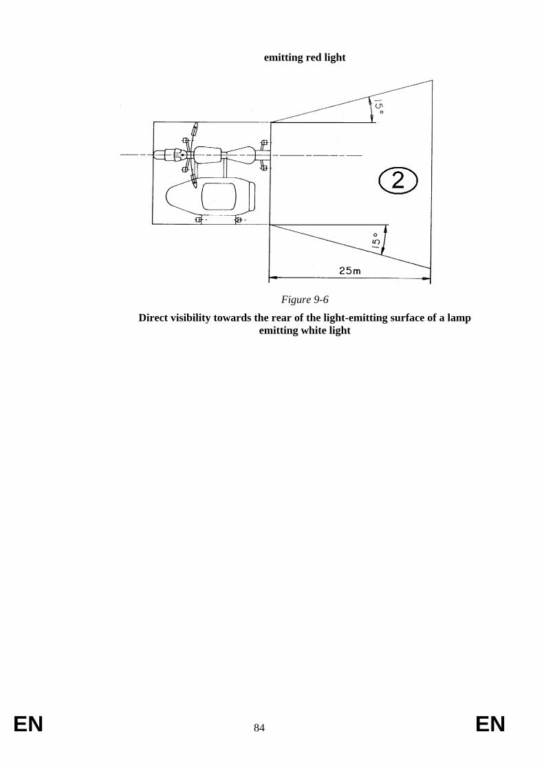
EN 84 EN
emitting red light
Figure 9-6
Direct visibility towards the rear of the light-emitting surface of a lamp
emitting white light
EN 85 EN
ANNEX X
Requirements on rearward visibility
1. Requirements
1.1. Vehicles of category L1e, L3e, and L4e shall meet all the relevant requirements of
UNECE regulation No. 81.
1.1.1. Vehicles of category L1e, L3e, and L4e may be fitted with Class II or III devices for
indirect vision which are type-approved according to UNECE regulation No. 46.
1.2. Vehicles of category L2e, L5e, L6e and L7e shall meet all the relevant requirements
of UNECE regulation No. 81 or UNECE regulation No. 46
1.2.1. Vehicles of category L2e, L5e, L6e and L7e meeting the relevant requirements of
UNECE regulation No. 81 may be fitted with Class II or III devices for indirect
vision which are type-approved according to UNECE regulation No. 46.
EN 86 EN
ANNEX XI
Requirements on roll-over protective structure (ROPS)
1. General Requirements
1.1. Vehicles of category L7e-B2 shall be equipped with a roll-over protection structure
(ROPS) and shall be so designed and constructed as to fulfil the essential purpose laid
down in this Annex. This condition is considered to be fulfilled if the prescriptions as
laid down in paragraphs 2. to 4.9. are complied with and if no part of the zone of
clearance has been entered by the protection structure, as well as no part of the zone of
clearance has been exposed outside the boundaries of the protection structure for any
period of time during the three tests.
2. Testing provisions.
2.1. General testing provisions
2.1.1. Tests made using special rigs are intended to simulate such loads as are imposed on a
protection structure, when the vehicle overturns. These test loads therefore concern push
forces. The tests as described in this Annex enable observations to be made on the
strength of the protection structure and any brackets attaching it to the vehicle and any
parts of the vehicle which transmit the test force.
2.2. Preparation of the test
2.2.1. The protection structure submitted for type-approval shall conform to the series
production specifications. It shall be attached in accordance with the manufacturer’s
declared method of attachment to the vehicle for which it is designed. A complete
vehicle is not required for the test, however, the protection structure and parts of the
vehicle on which it is attached for the tests shall represent an operating installation,
hereinafter referred to as the assembly.
2.2.2. The assembly shall be secured to the bedplate so that the members connecting the
assembly and the bedplate do not deflect significantly in relation to the protection
structure under loading. The method of attachment of the assembly to the bedplate shall
not of itself modify the strength of the assembly.
2.2.3. The assembly shall be supported and secured or modified so that all the test energy is
absorbed by the protection structure and its attachment to the rigid components of the
vehicle.
2.2.3.1. To comply with the requirements of paragraph 2.2.3. the modification shall lock any
vehicle wheel and axle suspension system so as to ensure that it does not absorb any of
the test energy.
2.2.4. For the tests the vehicle shall be fitted with all structural components of the series
production which may influence the strength of the protection structure or which may
be necessary for the strength test. Components which may create a hazard in the zone of
clearance shall also be fitted so that they may be examined to see whether the
requirements of paragraph 1.1. are fulfilled.
2.2.4.1. All components that the vehicle operator can remove shall be removed for the tests. If it

EN 87 EN
is possible to keep doors and windows open or to remove them completely when the
vehicle is in use, they shall be kept open or removed during the tests, so as not to
increase the strength of the roll-over protection structure.
3. Apparatus and equipment
3.1. Vertical loading tests (transverse and longitudinal)
3.1.1. Material, equipment and tie-down provisions shall be arranged in such a way as to
ensure that the assembly is firmly fixed to the bedplate, independently of wheels and
axles if present (i.e. the mounting shall override any wheel or axle suspension). See
figure 11-1
Figure 11-1
3.1.2. The vertical forces on the protection structure shall be applied in turn through a
transverse orientation stiff beam as well as longitudinal orientation stiff beam on
separate untested assemblies. The vertical longitudinal median plane, as considered in
the transverse direction in relation to the vehicle, of the beam shall be placed 300 mm
forward of the driver's seat R-point for the transverse test. The vertical longitudinal
median plane of the beam, as considered in the longitudinal direction in relation to the
vehicle, shall be placed inward of the vertical longitudinal plane touching the widest
point of the top one-third part of the protective structure at a distance equal to one-sixth
of the overall width of the top third part of the protective structure. The selection of the
left or right side of the protective structure of vehicle for the test shall be done in
accordance with paragraph 4.3. and the technical service shall clearly justify the
judgment criteria in the test report.

EN 88 EN
3.1.2.1. The beam shall be sufficiently stiff and have a bottom vertical face width of 150 ± 10
mm and it shall have a sufficient length as to cover the entire protective structure, even
when the latter is flexing under load.
3.1.2.2. Provision shall be made so that the load can be uniformly distributed normal to the
direction of loading.
3.1.2.3. The edges of the beam in contact with the protection structure may have a radius of
curvature of up to 25 mm.
3.1.2.4. Universal joints or the equivalent of it shall be incorporated to ensure that the loading
device does not constrain the structure in rotation or translation in any direction other
than the direction of loading.
3.1.2.5. Where the horizontal length of the protection structure to which the load is to be applied
does not constitute a straight line normal to the direction of application of the load, the
space shall be packed or otherwise filled so as to distribute the load horizontally over
this length.
3.1.3. Equipment shall be provided for measuring the energy absorbed by the protection
structure and the rigid parts of the vehicle to which it is attached, for example by
measuring the force applied along its vertical direction of application and the
corresponding vertical deflection of the beam relative to the horizontal plane passing
through the R-point of the driver’s seating position.
3.1.4. Visual means to assess any intrusion or exposure of the zone of clearance during the
force application shall be provided.
4. Test provisions
4.1. If during the test any part of the test setup fixing and restraining equipment shifts
significantly, the test shall be invalidated.
4.2. The protection structure to be tested need not be fitted with front, side or rear safety
glazing or any detachable panels, fittings and accessories which have no function of
structural strength and which cannot create a hazard in the event of overturning.
4.3. In the case of a vehicle whose driver’s seat is not on the median longitudinal plane of
the vehicle and/or in case of non-symmetrical strength of the structure, the vertical
longitudinal loading shall be on the side most likely to lead to infringement or exposure
of the zone of clearance during the test.
4.4. The protection structure shall be instrumented with the necessary equipment to obtain
the data required to draw the force-deflection diagram.
4.5. The rate of deflection under loading by the vertical force shall not be greater than 5
mm/s. As the load is applied, the values Fv (N) (i.e. static load force exerted by the
beam) and Dv (mm) (i.e. vertical deflection of the beam at the point of and in line with
the load application) shall be recorded simultaneously at deflection increments of 15
mm or less as to ensure sufficient accuracy. Once the initial application has commenced,
the load shall not be reduced until the test has been completed; but it is permitted to
EN 89 EN
cease increasing the load if desired, for example to record measurements.
4.6. If no structural cross member exists at the point of application, a substitute test beam
which does not add strength to the structure may be utilised for the test procedure.
4.7. The energy (J) absorbed by the structure in each vertical loading test shall be at least
equal to Ev = 1.4 x mtest, (where mtest (kg) equals the vehicle mass in running order, plus
the mass of propulsion batteries) and the minimum energy level to be achieved is
calculated as follows: Ev = Fv x Dv/1000. Fv shall not exceed 2 x mtest x g, even if the
minimum energy level to be achieved is not reached.
4.8. The longitudinal vertical loading condition shall be repeated taking into account a
simultaneously applied horizontal force component. First a static horizontal transverse
load equal to Fh = 0.5 x mtest x g (where g equals 9.81 m.s-2
), shall be applied onto the
widest point as described in paragraph 3.1.2. and on the side selected in accordance with
paragraph 4.3. Then, the longitudinal vertical loading shall be applied at the same
coordinates of the test performed without the horizontal transverse load, equal to 0.5 x
Fv(max) (where Fv(max) is the maximum value of Fv observed during the test performed
without the horizontal transverse load).
4.9. After each test, the final permanent deflection of the protection structure shall be
recorded and noted in the test report.

EN 90 EN
ANNEX XII
Requirements on safety belt anchorages and safety belts
1. General requirements for safety belt anchorages and the installation of safety belts
1.1. Vehicles of categories L2e, L5e, L6e and L7e fitted with bodywork and with a mass
in running order, plus the mass of propulsion batteries, exceeding 270 kg shall be
fitted with safety belt anchorages and safety belts complying with the requirements
of this Annex.
1.1.1. Further to definition (4) in Article 2 of this Regulation and for the purpose of this
Annex, a vehicle is deemed to have bodywork if there are structural elements beside
and/or behind the lowest seating position which exceed the height of the R-point of
the seating position in question. The area concerned is thus located in and behind the
transverse vertical plane passing through the R-point of the seating position in
question. Other seating positions, back rests, luggage compartments and racks, as
well as any other fittings or components mounted to them, shall not be taken into
account as being structural elements in this context. The technical service shall
clearly justify the judgment criteria in the test report.
1.2. Vehicles of categories L2e, L5e, L6e and L7e fitted with bodywork and with a mass
in running order, plus the mass of propulsion batteries, not exceeding 270 kg or
vehicles of categories L2e, L5e, L6e and L7e without bodywork may be fitted with
safety belt anchorages and/or safety belts, provided that these comply with the
requirements of this Annex.
1.3. The number of safety belt anchorages to be provided shall be sufficient to facilitate
the correct installation of the mandatory, voluntary or optionally installed type safety
belt on any given seat.
1.4. Safety belt anchorages shall conform to the 7/16-20 UNF 2B thread size and
tolerance specifications.
1.4.1. However, if the vehicle manufacturer has fitted safety belts as standard equipments
to specific seating positions, the safety belt anchorages for those seating positions
may have different characteristics than specified in paragraph 1.4.
1.4.2. Anchorage points complying with the specific provisions for the installation of
special-type safety belts (e.g. harness-type) may have different characteristics than
specified in paragraph 1.4.
1.5. It shall be possible to remove a safety belt without any remaining damage to the
actual safety belt anchorage point.
1.6. The determination of the R-point of a seating position shall be done as follows.
1.6.1. The R-point of a saddle shall be taken as declared by the vehicle manufacturer and
which shall be duly justified by means of appropriate vehicle design criteria taking
into account the characteristics of a 50th
percentile male manikin (i.e. Hybrid III
anthropomorphic test device) and its hip pivot point.
1.6.2. The R-point of a seat shall be established in accordance with the provisions laid
EN 91 EN
down in Appendix 3 of Part 2 to Annex VII of this Regulation.
Part 1 – Requirements applying to safety belt anchorages
1. Specific requirements for safety belt anchorages
1.1 The safety belt anchorages may be incorporated within the chassis, bodywork, the
seat or any other structure of the vehicle.
1.2. A single safety belt anchorage point may be used for the attachment of two ends of
the safety belts of adjacent seating positions.
1.3. The permitted locations of the effective safety belt anchorage points for all seating
positions are indicated in Figures 11-P1-1 and 11- P1-2 and are clarified below.
1.4. Position of the lower effective safety belt anchorages.
1.4.1. The α1 and α2 angles shall lie between 30o and 80
o in all normal positions of use of
the seat.
1.4.2. If seats are fitted with an adjustment system and the manufacturer declared torso
angle angle is less than 20o, the α1 and α2 angles referred to in the paragraph above
may lie between 20 and 80 in all normal positions of use of the seat.
1.4.3. The distance between the two vertical planes parallel to the longitudinal median
plane of the vehicle and passing through each of the two lower effective anchorages
L1 and L2 of the same safety belt shall not be less than 350 mm. The distance may be
reduced to 240 mm in case of a centre rear seating row position. The longitudinal
median plane of the seating position shall pass points L1 and L2 at no less than
120 mm from those points.
1.5. Location of the upper effective safety belt anchorages.
1.5.1. If a strap guide, D-ring or similar device affecting the position of an effective safety
belt upper anchorage is used, that position is determined in a conventional manner
by considering the position of the anchorage when. the safety belt is worn by an
occupant, represented by a 50th
percentile male manikin, with the seat adjusted to the
design position as specified by the vehicle manufacturer.
1.5.2. Points J1 and J2 shall be determined as follows:
Point J1 is determined in relation to the R-point by means of the following three
segments:
– RZ: segments of torso reference line measured form the R-point upwards
along the length 530 mm;
– ZX: segment perpendicular to the longitudinal median plane of the vehicle
measured from point Z in the direction of the anchorage and having a length
of 120 mm;
– XJ1: segment perpendicular to the plane defined by segments RZ and ZX
measured form point X forwards over a length of 60 mm;
Point J2 is determined by symmetry with point J1 about the longitudinal plane

EN 92 EN
vertically crossing the torso reference line of the relevant seat.
1.5.3. A single upper effective safety belt anchorage point shall comply with the following
requirements.
1.5.3.1. The upper effective safety belt anchorage point shall lie below the plane FN that is
perpendicular to the longitudinal median plane of the seating position and forms an
angle of 65o with the torso reference line. For rear seats this angle may be reduced to
60o. The plane FN may therefore not be perfectly horizontal and shall be located in
such a way as to intersect the torso reference line at a point D such that:
DR = 315 mm + 1.8 S.
However, if S does not exceed 200 mm:
DR = 675 mm.
1.5.3.2. The upper effective safety belt anchorage point shall also lie behind plane FK
perpendicular to the longitudinal median plane of the seat and intersecting the torso
reference line at an angle of 120o at a point B such that:
BR = 260 mm + S.
If S is not less than 280 mm, the vehicle manufacturer may alternatively opt to use:
BR = 260 mm + 0.8 S
1.5.3.3. The value S shall not be less than 140 mm.
1.5.3.4. The upper effective safety belt anchorage point shall also be located behind a vertical
plane that is perpendicular to the longitudinal median plane of the vehicle and which
passes through the R-point.
1.5.3.5. The upper effective safety belt anchorage point shall also be located above the
horizontal plane passing through the point C.
Point C is located 450 mm vertically above the R-point.
However, if distance S is not less than 280 mm and if the vehicle manufacturer did
not op to use the alternative formula for BR as provided in paragraph 1.5.3.2. of Part
1, the vertical distance of 500 mm between point C and the R-point shall be
applicable instead.
1.5.3.6. More than one actual upper safety belt anchorage point may be fitted, provided that
all resulting effective safety belt anchorage points meet the requirements of
paragraphs 1.5.3. to 1.5.3.5. of Part 1.
1.5.3.7. If the height of the upper safety belt anchorage point is manually adjustable without
the use of any tools, all selectable upper safety belt anchorage point positions and the
resulting effective safety belt anchorage points shall comply with the requirements as
set out in paragraphs 1.5.3. to 1.5.3.5. of Part 1. In such a case, the permitted area as
defined above may be enlarged by shifting it 80 mm upwards and downwards in the
vertical direction, however, the permitted area remains bounded by the horizontal
plane passing through point C. (See Figure 11- P1-1).
1.5.4. Anchorage points intended for special-type safety belts (e.g. harness-type).

EN 93 EN
1.5.4.1. Any additional upper effective safety belt anchorage point shall lie on the opposite
side of the first upper effective anchorage point in relation to the longitudinal median
plane of the seating position. The following requirements shall be met in addition:
– both upper safety belt effective anchorage points shall be located above the
horizontal plane passing through the point C;
– both upper safety belt effective anchorage points shal be located behind the
transverse plane passing through the torso reference line;
– A single actual safety belt anchorage point (i.e. two ends of the safety belt are
to be attached to a single anchorage point) shall be located within the area
common to two dihedrals bounded by vertical lines passing through the
points J1 and J2, and for each point forming an angle of 30 horizontally
between two vertical planes which are in turn related to the two vertical
longitudianal planes intersecting both J1 and J2 and forming an outward
angle of 10 and an inward angle of 20 with those longitudinal planes. See
Figure 11-2;
– Two separate actual safety belt anchorage points shall be located within each
of the respective areas formed by dihedrals bounded by vertical lines
passing through the points J1 and J2, and for each point forming an angle of
30 horizontally between two vertical planes which are in turn related to the
two vertical longitudianal planes intersecting both J1 and J2 and forming an
outward angle of 10 and an inward angle of 20 with those longitudinal
planes. See Figure 11-2. In addition, the two actual anchorage points shall
be so located that they would appear not to be more than 50 mm apart in
any direction when one of the points is mirrored in relation to the vertical
longitudinal plane passing through the R-point of the seating position in
question.
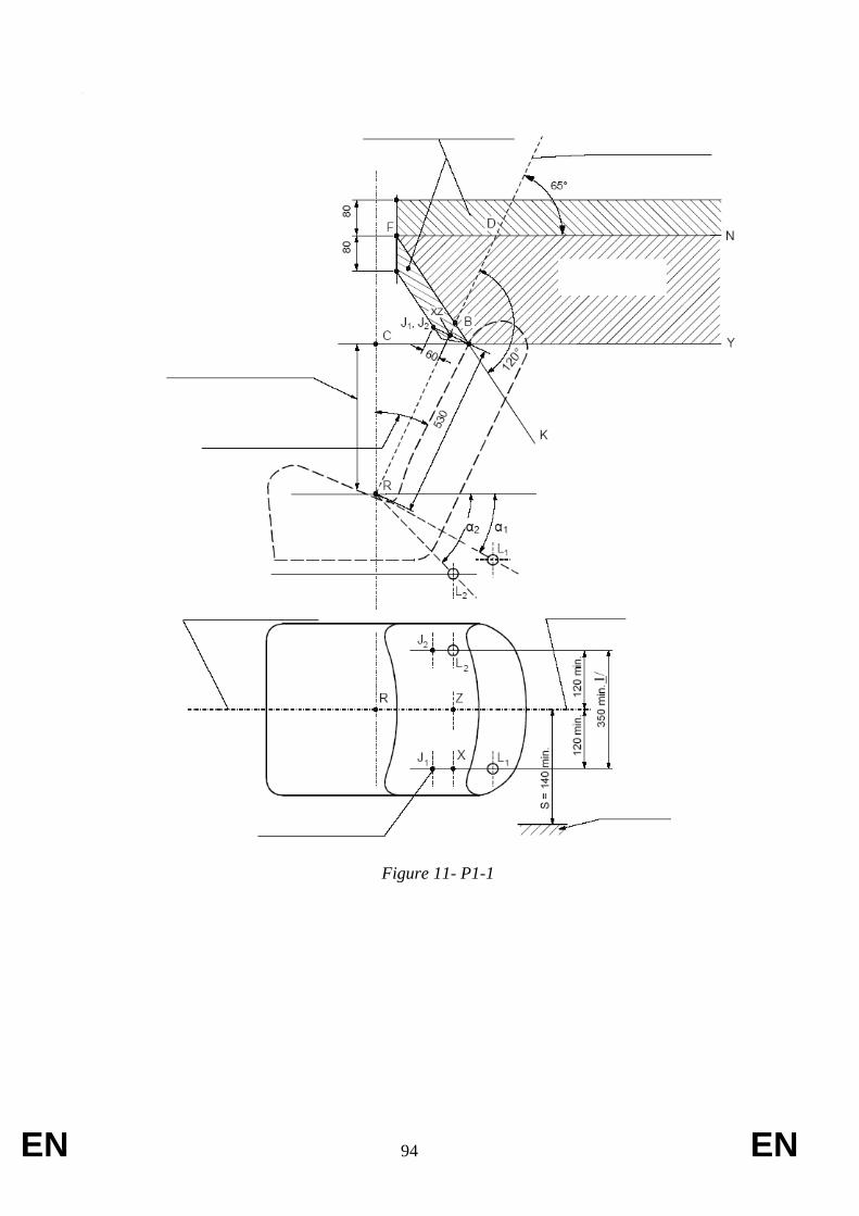
EN 94 EN
Permitted area
Torso reference line
Permitted area for adjustable upper anchorage points in accordance with paragraph 1.5.3.7. of Part 1 to this Annex
DR = 315 + 1.8 S BR = 260 + S except as otherwise specified in paragraphs 1.5.3.1. to 1.5.3.2. of Part 1 to this Annex
Distance as specified in paragraph 1.5.3.5. of Part 1 to this Annex
Angle as specified in paragraph 3.1.2.1. of Part 1 to this Annex
Longitudinal median plane of the seat Torso reference line
Effective upper safety belt anchorage point
Example for left-hand side outboard seat
Dimensions are in mm
Figure 11- P1-1
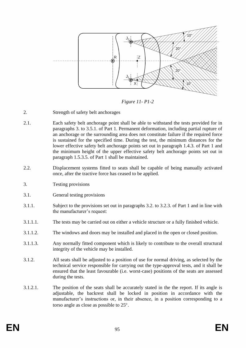
EN 95 EN
R Z
X
J
J
2
1
10°
20°
10°
20°
Figure 11- P1-2
2. Strength of safety belt anchorages
2.1. Each safety belt anchorage point shall be able to withstand the tests provided for in
paragraphs 3. to 3.5.1. of Part 1. Permanent deformation, including partial rupture of
an anchorage or the surrounding area does not constitute failure if the required force
is sustained for the specified time. During the test, the minimum distances for the
lower effective safety belt anchorage points set out in paragraph 1.4.3. of Part 1 and
the minimum height of the upper effective safety belt anchorage points set out in
paragraph 1.5.3.5. of Part 1 shall be maintained.
2.2. Displacement systems fitted to seats shall be capable of being manually activated
once, after the tractive force has ceased to be applied.
3. Testing provisions
3.1. General testing provisions
3.1.1. Subject to the provisions set out in paragraphs 3.2. to 3.2.3. of Part 1 and in line with
the manufacturer’s request:
3.1.1.1. The tests may be carried out on either a vehicle structure or a fully finished vehicle.
3.1.1.2. The windows and doors may be installed and placed in the open or closed position.
3.1.1.3. Any normally fitted component which is likely to contribute to the overall structural
integrity of the vehicle may be installed.
3.1.2. All seats shall be adjusted to a position of use for normal driving, as selected by the
technical service responsible for carrying out the type-approval tests, and it shall be
ensured that the least favourable (i.e. worst-case) positions of the seats are assessed
during the tests.
3.1.2.1. The position of the seats shall be accurately stated in the the report. If its angle is
adjustable, the backrest shall be locked in position in accordance with the
manufacturer’s instructions or, in their absence, in a position corresponding to a
torso angle as close as possible to 25.

EN 96 EN
3.2. Provisions for securing and restraining the vehicle during the test.
3.2.1. The method used to restrain the vehicle during the test shall not cause the anchorage
or anchorage areas to become reinforced and shall not interfere with the normal
deformation of the structure.
3.2.2. The method used to restrain the vehicle during the test is considered satisfactory if it
has no effect on an area extending throughout the width of the structure and if the
vehicle or structure is locked or attached at the front at an overall distance of at least
500 mm from the actual anchorage point to be tested and held or attached at the rear
at an overall distance of at least 300 mm from the actual anchorage point to be
tested.
3.2.3. It is recommended that the structure rests on supports directly below the wheel axes
or, if this is not possible, directly below the wheel suspension points.
3.3. General test requirements.
3.3.1. All the anchorages within the same group of seats shall be tested simultaneously.
3.3.2. The tractive force shall be applied forwards at an angle of 10o ± 5
o above the
horizontal in a plane parallel to the longitudinal median plane of the vehicle.
3.3.3. The loading shall begin as quickly as possible. The anchorages shall withstand the
specified load for at least 0.2 seconds.
3.3.4. The traction devices to be used for the tests as described in paragraphs 3.4. to
3.4.5.2. of Part 1 shall comply with the specifications as laid down in Annex 5 to
UNECE regulation No. 1420
. The width of the traction device shall be selected as to
correspond with the design value of the width between the lower effective safety belt
anchorages or as close as possible.
3.3.5. Safety belt anchorages for seats fitted with upper anchorages shall be tested under
the following conditions:
3.3.5.1. Outboard front seating positions:
In case of safety belts incorporating a intertia reel retractor attached to a separate
lower side anchorage point:
– the anchorages are subjected to the test laid down in paragraphs 3.4.1. to
3.4.1.3. of Part 1 in which the forces are applied to them by means of a
device reproducing the geometry of a three-point belt incorporating an
intertia reel retractor attached to a lower side anchorage and a D-ring acting
through the upper anchorage.
In case of safety belts not incorporating a intertia reel retractor attached to a separate
lower side anchorage point:
– the anchorages shall be subjected to the test laid down in paragraphs 3.4.2. to
3.4.2.2. of Part 1 in which the forces are applied to them by means of a
20 UN regulation 14 first reference

EN 97 EN
device reproducing the geometry of a three-point non-inertia reel belt;
– the lower anchorages shall in addition be subjected to the test laid down in
paragraphs 3.4.3. to 3.4.3.1. of Part 1 in which the forces are transferred to
the lower anchorages by means of a device representing a lap belt;
– the two tests may be carried out on two different structures at the request of
the manufacturer.
If the height of the upper safety belt anchorage point is manually adjustable without
the use of any tools, it shall be set in the least favourable (i.e. worst-case) position as
decided by the technical service.
In case of multiple upper safety belt anchorage points for use with a special-type
safety belt (e.g. harness-type), they shall all be subjected to the test required in
paragraphs 3.4.5. to 3.4.5.2. of Part 1, in which the forces are applied to them by
means of a device reproducing the geometry of the type of safety belt intended to be
attached to those anchorages.
3.3.5.2. Rear outboard seating positions and/or centre seating positions:
In case of three-point safety belts incorporating a intertia reel retractor attached to a
separate lower side anchorage point:
– the anchorages are subjected to the test laid down in paragraphs 3.4.1. to
3.4.1.3. of Part 1 in which the forces are applied to them by means of a
device reproducing the geometry of a three-point belt incorporating an
intertia reel retractor attached to a lower side anchorage and a D-ring acting
through the upper anchorage.
In case of three-point safety belts not incorporating a intertia reel retractor attached
to a separate lower side anchorage point:
– the anchorages shall be subjected to the test laid down in paragraphs 3.4.2. to
3.4.2.2. of Part 1 in which the forces are applied to them by means of a
device reproducing the geometry of a three-point non-inertia reel belt;
– the lower anchorages shall in addition be subjected to the test laid down in
paragraphs 3.4.3. to 3.4.3.1. of Part 1 in which the forces are transferred to
the lower anchorages by means of a device representing a lap belt;
– the two tests may be carried out on two different structures at the request of
the manufacturer.
If the height of the upper safety belt anchorage point is manually adjustable without
the use of any tools, it shall be set in the least favourable (i.e. worst-case) position as
decided by the technical service.
In case of multiple upper safety belt anchorage points for use with a special-type
safety belt (e.g. harness-type), they shall all be subjected to the test required in
paragraphs 3.4.5. to 3.4.5.2. of Part 1, in which the forces are applied to them by
means of a device reproducing the geometry of the type of safety belt intended to be
attached to those anchorages.
3.3.6. Safety belt anchorages for seating positions not fitted with upper anchorages shall be
tested under the following conditions:

EN 98 EN
3.3.6.1. Outboard front seating positions:
In case of two-point or lap safety belts:
– not permitted.
3.3.6.1. Rear outboard seating positions and/or centre seating positions:
In case of two-point or lap safety belts:
– the lower anchorages shall be subjected to the test laid down in paragraphs
3.4.3. to 3.4.3.1. of Part 1 in which the forces are transferred to the lower
anchorages by means of a device representing a lap belt.
3.3.7. If the safety belt systems which are to be installed in the vehicle require the use of
specific equipment such as brackets, rollers, additional anchorages or guides,
preventing the testing straps or cables to be attached directly to the anchorages
without the use of such specific equipment, such special equipment shall be mounted
and used during all tests as appropriate.
3.4. Specific requirements for the tests to be carried out on vehicles having an mass in
running order, plus the mass of propulsion batteries, of not exceeding 600 kg.
3.4.1. Test in three-point belt configuration incorporating a retractor having a D-ring,
pulley or strap guide at the upper actual safety belt anchorage.
3.4.1.1. A reverser, pully or guide for the cable or strap having the characteristics needed in
order to transfer the forces from the traction device is attached to the upper
anchorages. A normal safety belt system may also be used instead.
3.4.1.2. A test loading of 675 daN ± 20 daN shall be applied to a shoulder belt traction
device which is in turn attached to the belt anchorages by means of a cable or strap
reproducing the geometry of the upper diagonal strap of the corresponding safety
belt.
3.4.1.3. At the same time a tractive force of 675 daN ± 20 daN shall be applied to a lap belt
traction device which is in turn attached to the two lower anchorages.
3.4.2. Test in three-point belt configuration without a retractor or with a retractor mounted
directly to the upper actual anchorage point.
3.4.2.1. A test loading of 675 daN ± 20 daN shall be applied to a shoulder belt traction
device which is in turn attached to the upper anchorage and to the opposite lower
belt anchorage of the same safety belt using, if fitted as standard equipement by the
manufacturer, a retractor fixed at the upper actual safety belt anchorage.
3.4.2.2. At the same time a tractive force of 675 daN ± 20 daN shall be applied to a lap belt
traction device which is in turn attached to the two lower anchorages.
3.4.3. Test in lap-belt configuration.
3.4.3.1. A test loading of 1110 daN ± 20 daN shall be applied to a lap belt traction device
which is in turn attached to the two lower anchorages.
EN 99 EN
3.4.4. Additional test requirements in case of safety belt anchorage points located wholly
within the seat structure or dispersed between the vehicle structure and the seat
structure.
3.4.4.1. Where this is the case, the three specific safety belt configuration tests as laid down
in paragraphs 3.4.1., 3.4.2. and 3.4.3. of Part 1 shall be performed while at the same
time an additional force, as specified below, is superimposed for each seat and/or for
each group of seats.
3.4.4.2. If applicable, a longitudinal and horizontal force equal to ten times the weight of the
complete seat is applied to the centre of gravity of the seat structure in question. The
additional force shall be applied directly to the seat structure through a separate force
application device.
3.4.5. Test in special-type belt configuration (configurations other than those for three-
point belt or lap-belt).
3.4.5.1. A test loading of 675 daN ± 20 daN shall be applied to a shoulder belt traction
device which is in turn attached to the belt anchorages meant for a special-type safe
belt, by means of cables or straps reproducing the geometry of the upper diagonal
strap or straps of the corresponding safety belt.
3.4.5.2. At the same time a tractive force of 675 daN ± 20 daN shall be applied to a lap belt
traction device which is in turn attached to the two lower anchorages.
3.5. Specific requirements for the tests to be carried out on vehicles having an mass in
running order, plus the mass of propulsion batteries, of more than 600 kg or when
the vehicle manufacturer chooses to fulfil these requirements on a voluntary basis.
3.5.1. Vehicles covered by the criteria set out in paragraph 3.5. of Part 1 shall meet all the
relevant requirements of UNECE regulation No. 14, with regard to anchorages for
safety belts intended for adult occupants, as prescribed for vehicle category M1.
3.6. If an ISOFIX anchorage system or an anchorage system which resembles ISOFIX is
fitted optionally to the vehicle, all relevant location, marking and strength
requirements as laid down in UNECE regulation No. 14 for such ISOFIX systems
shall be met.
3.6. Test report requirements
3.6.1. The deformation of the safety belt anchorage points and the load supporting
structures resulting from the application of the loads as specified in paragraphs 3.4.
to 3.5.1. shall be accurately recorded after the tests and included in the test report.
Part 2 – Requirements applying to the installation safety belt
1. In the absence of specific requirements for vehicles of category L2e, L5e, L6e and
L7e in UNECE regulation No. 16, vehicles of these categories which are fitted with
safety belts shall meet all relevant requirements of that regulation as prescribed for
vehicle category N1, while in addition taking into account the following:

EN 100 EN
1.1. Without prejudice to the requirements of paragraphs 1.1. and 1.2. of this Annex,
concerning the mass in running order, safety belts shall be fitted to all seating
positions consisting of seats.
1.1.1. The driver’s seating position shall in such a case always be fitted with a three-point
or harness-type safety belt (i.e. also in the case of a centre seating position for the
driver).
1.2. Vehicles of category L7e-A2, L7e-B2 and L7e-C shall be fitted with three-point or
harness-type safety belts on all seating positions, regardless of the vehicle mass in
running order.
1.3. Any reference in UNECE regulation No. 16 made to UNECE regulation 14 shall be
understood as a reference to Part 1, where appropriate.
1.4. Safety belts may be fitted to seating positions consisting of saddles. In such a case,
two-point or lap safety belts may be accepted instead of three-point safety belts,
however, the remaining relevant requirements shall be met.
1.5. All safety belts shall be type-approved and fitted in accordance with the safety belt
manufacturer’s specifications.
EN 101 EN
ANNEX XIII
Requirements on seating positions (saddles and seats)
1. Requirements
1.1. Vehicles shall be fitted with at least one seat or saddle.
1.1.1. All seating positions shall be forward facing.
1.2. Vehicles without bodywork may have saddles.
1.3. Vehicles of category L2e, L5e, L6e and L7e which are fitted with bodywork shall
have seats.
1.3.1. Further to definition (4) in Article 2 of this Regulation and for the purpose of this
Annex, a vehicle is deemed to have bodywork if there are structural elements beside
and/or behind the lowest seating position which exceed the height of the R-point of
the seating position in question. The area concerned is thus located in and behind
the transverse vertical plane passing through the R-point of the seating position in
question. Other seating positions, back rests, luggage compartments and racks, as
well as any other fittings or components mounted to them, shall not be taken into
account as being structural elements in this context. The technical service shall
clearly justify the judgment criteria in the test report.
1.4 The determination of the R-point of a seating position shall be done as follows.
1.4.1. The R-point of a saddle shall be taken as declared by the vehicle manufacturer and
which shall be duly justified by means of appropriate vehicle design criteria taking
into account the characteristics of a 50th
percentile male manikin (i.e. Hybrid III
anthropomorphic test device) and its hip pivot point.
1.4.2. The R-point of a seat shall be established in accordance with the provisions laid
down in Appendix 3 of Part 2 to Annex VII of this Regulation.
1.5. All seats shall have seat backs.
1.5.1. In order to assess the functionality of a seat back, it shall be possible to carry out at
least one of the two procedures below for each seat.
1.5.1.1. The procedure for the determination of the H-point following the prescriptions as
laid down in Annex 3 of UNECE regulation No. 17 shall be carried out successfully
(i.e. not taking into account any exemptions provided in that regulation).
1.5.1.2. Only in case that the above mentioned procedure cannot be carried out correctly for
a specific seat, which shall be demonstrated satisfactorily, it is permitted to instead
place a 50th
percentile male manikin (i.e. Hybrid III anthropomorphic test device)
on that seat, with the seat adjusted to the design position as specified by the vehicle
manufacturer. In such a case, the R-point of the seat in question shall be taken as
declared by the vehicle manufacturer and which shall be duly justified by means of
appropriate vehicle design criteria taking into account the characteristics of a 50th
percentile male manikin and its hip pivot point. The technical service shall clearly
justify the judgment criteria in the test report. If this alternative procedure can also

EN 102 EN
not be carried out correctly, the seat is deemed not to comply with the requirements
of this Annex.
1.6. Spaces which are not designated as being seating positions, but which resemble
seating positions, shall not be permitted.
1.6.1. Spaces which resemble seats and on which a 5th
percentile adult female can take
place, shall be considered seats which shall, as a consequence, meet all relevant
requirements of this Annex.
1.7. The height of the R-point of the seating position of the driver or rider shall be ≥ 540
mm in case of vehicles of categories L1e, L3e and L4e and ≥ 400 mm in case of
vehicles of categories L2e, L5e, L6e and L7e, as measured from the ground surface.
1.7.1. If the vehicle is equipped with systems which can change the vehicle’s riding
height, it shall be set in the normal running condition as specified by the vehicle
manufacturer.
1.8. All seats and saddles which are fitted with safety belt anchorage points and/or
safety belts shall be capable of withstanding a deceleration of 10 g for 20 ms in
forward direction without breakage. If fitted, locking and adjustment systems, as
well as displacement systems shall not malfunction or release. Displacement
systems fitted to seats shall be capable of being manually activated once after being
subjected to the deceleration.
1.8.1. Compliance with paragraph 1.8. shall be shown as follows:
– for seats:
– by submitting representative parts of the vehicle to a deceleration of
10 g in forward direction which shall last at least 20 ms; or
– by performing the test as laid down in paragraphs 3.4.4. to 3.4.4.2. of
Part 1 to Annex XI;
– for saddles:
– by extending in the forward direction, in its centre of gravity, a force
equal to ten times the weight of the complete saddle in question.
1.9. Seating positions provided in side-cars
1.9.1. The requirements as laid down in paragraph 1.7. do not apply for seating positions
provided in side-cars.
2. Child restraint systems
2.1. Child restraint systems complying with UNECE regulation No. 4421
may be
recommended by the vehicle manufacturers for use in vehicles of categories L2e,
L5e, L6e and L7e fitted with safety belts and/or ISOFIX.
2.1.1. In such a case, all relevant requirements as laid down in UNECE regulation No. 16
21 UN regulation 44 first reference
EN 103 EN
with regard to the installation of child restraint systems shall be met, including the
requirements concerning information provided in the instruction manual of the
vehicle.
2.2. Child restraint systems complying with UNECE regulation No. 44 may be
recommended by the vehicle manufacturers for use in side-cars of vehicles of
category L4e fitted with safety belts and/or ISOFIX.
2.2.1. In such a case, the safety belt anchorages shall comply with the requirements as laid
down in paragraphs 1.3. to 1.6.2. of Annex XI and paragraphs 1. to 3.6.1. of part 1
to Annex XI, however, seats in side-cars may be fitted with two-point lap belts.
2.2.2. All relevant requirements as laid down in UNECE regulation No. 16 with regard to
the installation of child restraint systems shall be met, including the requirements
concerning information provided in the instruction manual of the vehicle.

EN 104 EN
ANNEX XIV
Requirements on steer-ability, cornering properties and turn-ability
1. Requirements
1.1. Vehicles of category L1e and L3e shall be tested according to the provisions as set
out in paragraphs 2. to 2.6. and meet the relevant requirements.
1.2. Vehicles of category L2e, L4e, L5e, L6e and L7e shall be tested according to the
provisions as set out in paragraphs 2. to 2.8. and meet the relevant requirements. In
addition, these vehicles shall meet the specific construction requirements as laid
down in paragraphs 1.2.1. to 1.2.2.1.
1.2.1. Vehicles shall be constructed in such a way that each of the vehicle’s wheels is
capable of rotating at different individual speeds at all times. It is permitted that a
device such as a differential is installed which may be locked automatically or by
external means, however, such device shall be normally unlocked.
1.2.1.1. It is not permitted that a locking function of such a device is used to comply with
specific braking requirements as laid down in Annex III, in particular concerning
braking action being required, operating on all the vehicle’s wheels.
1.2.2. Vehicles of category L2e, L5e, L6e and L7e which are fitted with bodywork shall
be equipped with a device for reversing which can be operated from the driver’s
position.
1.2.2.1. Further to definition (4) in Article 2 of this Regulation and for the purpose of this
Annex, a vehicle is deemed to have bodywork if there are structural elements beside
and/or behind the driver’s seating position which exceed the height of its R-point.
The area concerned is thus located in and behind the transverse vertical plane
passing through the R-point of the driver’s seat. Other seating positions, back rests,
luggage compartments and racks, as well as any other fittings or components
mounted to them, shall not be taken into account as being structural elements in this
context. The technical service shall clearly justify the judgment criteria in the test
report.
2. Test provisions
2.1. The tests shall be conducted on a level surface affording good adhesion.
2.2. During the tests, the vehicle shall be loaded to its technically permissible maximum
mass.
2.3. The tyre pressures shall be adjusted to the values as specified by the vehicle
manufacturer for the relevant load condition.
2.4. It shall be possible to steer a vehicle from a straight ahead direction into a spiral
with a final turning circle radius of 12 m at a speed of at least 6 km/h and in order to
demonstrate compliance, one steering movement shall be made to the right and one
to the left.
2.5. It shall be possible to leave a curve with a turning circle radius of ≤ 50 m at a

EN 105 EN
tangent without unusual vibration in the steering equipment at 50 km/h or at the
maximum vehicle design speed, if this is lower.
2.6. It shall be possible to travel along a straight section of road surface without unusual
steering corrections by the rider or driver and without unusual vibration in the
steering system at 160 km/h for vehicles with a maximum design speed ≥ 200 km/h,
at 0.8 x Vmax for vehicles with a maximum design speed < 200 km/h or the actual
maximum speed which the vehicle can attain in the test load condition, if this is
lower.
2.7. When a vehicle of category L2e, L4e, L5e, L6e or L7e is driven in a circle with its
steered wheels at approximately half lock and a constant speed of at least 6 km/h,
the turning circle shall remain the same or become larger if the steering control is
released.
2.8. In case vehicles of category L4e and if the side-car can be detached from the
motorcycle with the aim that the motorcycle can be used without it, the motorcycle
itself shall, in addition to the requirements as laid down in paragraph 1.2., also fulfil
the requirements for solo motorcycles as specified in paragraph 1.1.
EN 106 EN
ANNEX XV
Requirements on the installation of tyres
1. General requirements
1.1. Subject to the provisions of paragraph 1.2. to 1.2.2. below, every tyre fitted to the
vehicle, including where applicable any spare tyre, shall be type-approved according
to UNECE regulation No. 75.
1.1.1. Tyres which according to UNECE regulation No 75 are deemed suitable for fitment
on vehicles of categories L2e and L5e shall equally be deemed suitable for fitment on
vehicles of categories L6e and L7e.
1.2. In case the vehicle is designed for conditions of use which are incompatible with the
characteristics of tyres type-approved according to UNECE regulation No. 75 and it
is therefore necessary to fit tyres with different characteristics, the requirements of
paragraph 1.1. do not apply, provided that all of the following conditions are met:
1.2.1. The tyres shall be type-approved according to either Directive 92/23/EC22
,
Regulation (EC) No 661/200923
or UNECE regulation No. 106 and;
1.2.2. The approval authority and technical service are satisfied that the tyres fitted are
suitable for the operating conditions of the vehicle. The nature of the exemption and
motivation of acceptance shall be clearly stated in the test report.
2. Tyre fitment
2.1. All of the tyres normally fitted to one axle, except those on side-cars of L4e category
vehicles, shall be of the same type.
2.2. The space in which each wheel revolves shall be such as to allow unrestricted
movement when using the maximum permissible size of tyres and rim widths, taking
into account the minimum and maximum wheel off-sets if applicable, within the
minimum and maximum suspension and steering constraints as declared by the
vehicle manufacturer. This shall be verified by performing the checks for the largest
and the widest tyre in each space, taking into account the applicable rim size and the
maximum allowed section width and outer diameter of the tyre, in relation to the tyre
size designation as specified in the relevant EU Directive, EU Regulation or UNECE
regulation. The checks shall be performed by rotating a representation of the tyre’s
maximum envelope, and therefore not just the actual tyre, in the space for the wheel
in question.
2.2.1. The permissible dynamic growth of bias and bias/belted construction tyres which are
type-approved according to UNECE regulation No. 75 depends on the speed
category symbol and the category of use. To ensure an unrestricted choice of bias
and bias/belted replacement tyres for the end-user of the vehicle, the vehicle
manufacturer shall take into account the largest tolerance laid down in paragraph 4.1.
of Annex 9 to UNECE regulation No 75 (i.e. Hdyn = H 1.18) irrespective of the
22 92/23/EC OJ L 129, 14.5.1992, p. 95 23 (EC) 661/2009
EN 107 EN
speed category and category of use of the tyres fitted to vehicle submitted for type-
approval.
2.3. The technical service may agree to an alternative test procedure (e.g. virtual testing)
to verify that the requirements of paragraph 2.2. to 2.2.1. are met, provided that the
clearance between the tyre’s maximum envelope and vehicle structure exceeds 10
mm in all locations.
3. Load capacity
3.1. The maximum load rating of each tyre with which the vehicle is fitted shall be at
least equal to the following:
– the maximum permissible mass on the axle where the axle is equipped with
one tyre only;
– half of the maximum permissible mass on the axle where the axle is equipped
with two tyres in single formation;
– 0,54 times the maximum permissible mass on the axle where the axle is
equipped with two tyres in dual (twin) formation;
– 0,27 times the maximum permissible mass on the axle where the axle is
equipped with two sets of tyres in dual (twin) formation;
– with reference to the maximum permissible mass on each axle as declared by
the vehicle manufacturer.
3.1.1. The load capacity index as indicated in the information document shall be the lowest
grade which is compatible with the maximum permissible load on the tyre in
question. The actual fitment of a tyre with any higher grade shall be permitted.
3.2. The relevant information shall be stated clearly in the instruction manual of the
vehicle in order to ensure that suitable replacement tyres with an appropriate load
capacity shall be fitted when necessary, once the vehicle has been put into service.
4. Speed capacity
4.1. Every tyre with which the vehicle is normally fitted shall bear a speed category
symbol.
4.1.1. The speed category symbol shall be compatible with the maximum vehicle design
speed.
4.1.1.1. The speed category as indicated in the information document shall be the lowest
grade which is compatible with the maximum vehicle design speed. The actual
fitment of a tyre with any higher grade shall be permitted.
4.1.2. In case of tyres of speed categories V, W, Y and Z, the adjusted load rating as
specified in the relevant Directive, EU Regulation or UNECE regulation shall be
taken into account.
4.1.3. In the case of tyres of class C2 or C3, the adjusted load rating as specified in
paragraph 2.29. of UNECE regulation No. 54 shall be taken into account.
EN 108 EN
4.2. The requirements of paragraph 4.1.1. to 4.1.3. shall not apply in the following
situations:
4.2.1. In the case of temporary-use spare units.
4.2.2. In the case of vehicles normally equipped with ordinary tyres and occasionally fitted
with snow tyres where in such a case the speed category symbol of the snow tyre
shall correspond to a speed either greater than the maximum vehicle design speed or
not less than 130 km/h (or both). However, if the maximum vehicle design speed is
greater than the speed corresponding to the lowest speed category symbol of the
fitted snow tyres, a maximum speed warning label, specifying the lowest value of the
maximum speed capability of the fitted snow tyres, shall be displayed inside the
vehicle in a prominent position or as close as possible to the instrument cluster if the
vehicle does not have an interior, readily and permanently visible to the driver.
4.3. The relevant information shall be stated clearly in the vehicle owner’s handbook in
order to ensure that suitable replacement tyres with an appropriate speed capacity
shall be fitted when necessary, once the vehicle has been put into service.
EN 109 EN
ANNEX XVI
Requirements on vehicle maximum speed limitation plate and its location on the vehicle
1. General requirements
1.1. Vehicles of category L7e-B1 shall be fitted with a plate on which the maximum
vehicle design speed is indicated.
1.2. Vehicles of categories other than L7e-B1 may be fitted with a plate on which the
maximum vehicle design speed is indicated, provided that the requirements as laid
down in this Annex are met.
2. Specific requirements concerning the plate
2.1. All characters on the plate shall be formed by retro-reflective material which has
been type-approved as Class D, E or D/E according to UNECE regulation No. 10424
.
2.2. The surface shall consist of a white round plate with a diameter of 200 mm.
2.2.1. The white round shaped non-retro-reflective base with a diameter of 200 mm may
also be fixed on a larger and differently shaped surface such as bodywork, provided
that all requirements are still complied with.
2.3. The number indicated on the plate shall be marked in orange digit characters.
2.3.1. The font type to be used shall be normal, clearly legible, upright and common. All
digits on the plate shall have the same font size. Handwriting styles or italic scripts
shall not be permitted.
2.3.2. Each digit character shall be at least 100 mm in height and 50 mm in width, with the
exception of the number “1” which may be narrower than 50 mm.
2.4. In case of vehicles intended and equipped for operation in territories where metric
values are used, the characters “km/h” shall be stated under the speed indication.
2.4.1. The overall dimensions of the term “km/h” shall be at least 40 mm in height and 60
mm in width.
2.5. In case of vehicles intended and equipped for operation in territories where imperial
values are used, the characters “mph” shall be stated under the speed indication.
2.5.1. The overall dimensions of the term “mph” shall be at least 40 mm in height and 60
mm in width.
2.6. If vehicles are intended and equipped for operation in territories where both metric
and imperial values are used, both versions of the speed limitation plate shall be
fitted to the vehicle, while complying with all requirements of this Annex.
3. Location, visibility and characteristics of the plate
24 UN regulation 104 first reference
EN 110 EN
3.1. The plate shall consist of a virtually flat surface.
3.2. Position of the plate in relation to the longitudinal median plane of the vehicle:
3.2.1. The centre point of the plate shall not be situated to the left of the longitudinal
median plane of the vehicle.
3.3. Position of the plate in relation to the vertical longitudinal plane of the vehicle:
3.3.1. The plate shall be perpendicular to the longitudinal plane of the vehicle.
3.3.2. The right-hand edge of the plate may not be situated to the right of the vertical plane
which is parallel to the longitudinal median plane of the vehicle and touches the
extreme outer edge of the vehicle.
3.4. Position of the plate in relation to the vertical transverse plane:
3.4.1. The plate may be inclined to the vertical:
3.4.1.1. At not less than -5º and not more than 30º, provided that the height of the upper edge
of the plate is not more than 1.20 m from the ground surface;
3.4.1.2. At not less than -15º and not more than 5º, provided that the height of the upper edge
of the plate is more than 1.20 m from the ground surface.
3.5. Height of the plate from the ground surface:
3.5.1. The height of the lower edge of the plate from the ground surface shall not be less
than 0.30 m.
3.5.2. The height of the upper edge of the plate from the ground surface shall not exceed
1.20 m. However, where it is not practicable to comply with the height provision due
to the construction of the vehicle, the maximum height may exceed 1.20 m, provided
that it is as close to that limit as the constructional characteristics of the vehicle
allow, and shall in no case exceed 2.00 m.
3.6. Geometrical visibility:
3.6.1. If the height of the upper edge of the plate from the ground surface does not exceed
1.20 m, the plate shall be visible in the whole space included within the following
four planes:
– the two vertical planes touching the two lateral edges of the plate and
forming an angle measured outwards of 30º in relation to the longitudinal
median plane of the vehicle;
– the plane touching the upper edge of the plate and forming an angle measured
upwards of 15º with the horizontal;
– the horizontal plane through the lower edge of the plate.
3.6.2. If the height of the upper edge of the plate from the ground surface exceeds 1.20 m,
the plate shall be visible in the whole space included within the following four

EN 111 EN
planes:
– the two vertical planes touching the two lateral edges of the plate and
forming an angle measured outwards of 30º in relation to the longitudinal
median plane of the vehicle;
– the plane touching the upper edge of the plate and forming an angle measured
upwards of 15º with the horizontal;
– the plane touching the lower edge of the plate and forming an angle measured
downwards of 15º with the horizontal.
4. Test procedure
4.1. Determination of the vertical inclination and height of the plate from the ground
surface:
4.1.1. The vehicle is placed on a smooth ground surface with the vehicle's mass adjusted to
that of the manufacturer's declared mass in running order, plus the mass of
propulsion batteries, before the measurements are made.
4.1.2. If the vehicle is equipped with systems which can change the vehicle’s riding height,
it shall be set in the normal running condition as specified by the vehicle
manufacturer.
4.1.3. If the plate is facing downwards, the measurement result concerning the inclination is
expressed in minus.

EN 112 EN
ANNEX XVII
Requirements on vehicle occupant protection, including interior fittings and vehicle doors
Part 1 – Requirements concerning the interior fittings of vehicles
1. Requirements
1.1. Vehicles of category L2e, L5e, L6e and L7e which are fitted with bodywork shall
meet the following requirements.
1.1.1. The interior of the vehicle is divided in three main areas:
– interior zone 1:
– in front of the torso reference line in relation to the seating position
of the driver;
– above the R-point of the seating position of the driver.
– interior zone 2:
– in front of the torso reference line in relation to the seating position
of the driver;
– below the R-point of the seating position of the driver.
– interior zone 3:
– behind the torso reference line in relation to the seating position of
the driver;
– in front of the torso reference line in relation to the seating position
of the most rearward passenger;
– above the R-point of the lowest seating position other than that of the
driver.
1.1.1.1. Further to definition (4) in Article 2 of this Regulation and for the purpose of this
Annex, a vehicle is deemed to have bodywork, and thus an interior, if the vehicle is
fitted with safety glazing, side doors, side pillars and/or a roof creating an enclosed
or partly enclosed compartment and the technical service shall clearly justify the
judgment criteria in the test report.
1.1.2. All vehicle doors and glazing shall be in the closed position. If a roof is fitted to the
vehicle which can be opened or removed, it shall be in the closed position.
1.1.3. Other elements in the interior which have multiple positions of use, such as levers,
sun visors, cup holders, ash trays, ventilation outlets, knobs and buttons, shall be
assessed in all positions in which they can be placed, including all intermediate
positions.
1.1.4. Materials which are softer than 50 Shore (A) hardness shall be disregarded in the
assessment of compliance with the requirements. The technical service may
therefore request such materials to be removed during the type-approval checks.
1.1.5. The front side of seat structures shall be disregarded. The rear side of seat structures
in interior zone 3 shall comply with the requirements as laid down in Part 1 (if
EN 113 EN
applicable with the soft materials removed), however, the rear side of seat structures
may alternatively comply with the relevant requirements for seat areas 1, 2 and 3 as
laid down in UNECE regulation No. 17, prescribed for vehicle category M1.
1.1.6. Testing apparatus.
1.1.6.1. A head form testing apparatus shall be used in interior zone 1 and 3 to simulate
situations where edges may be contacted by the head of an occupant. The head form
testing apparatus consists of a sphere with a diameter of 165 mm. Where necessary,
a force not exceeding 2.0 daN shall be applied with the testing apparatus in order to
expose edges.
1.1.6.2. A knee form testing apparatus shall be used in interior zone 2 to simulate situations
where edges may be contacted by the knees of an occupant. See Appendix 1 of Part
1 for the specifications of the knee form testing apparatus. Where necessary, a force
not exceeding 2.0 daN shall be applied with the testing apparatus in order to expose
edges.
1.1.6.3. The testing apparatus itself shall not be moved outside of the zone which is being
assessed, however, the head form testing apparatus may be moved below the lower
horizontal boundary of interior zone 1 and the knee form testing apparatus may be
moved above the upper horizontal boundary of interior zone 2 as long as the
relevant point of contact still lies within the zone which is being assessed (i.e. no
overlap of contact points). If the interior of the vehicle is open to the outside, for
instance because of the lack of doors or roof, an imaginary exterior boundary shall
be taken into account as if the entire vehicle and thus its openings are covered with
a thin plastic wrapping sheet.
2. Specific requirements and tests.
2.1. Interior zone 1:
2.1.1. In this zone, a head form testing apparatus shall be moved in all directions possible.
All contactable edges, except those mentioned below, shall be rounded with a radius
of curvature of at least 3.2 mm.
2.1.2. Contactable edges above the level of the instrument panel which are either a part of
the instrument panel or of elements mounted directly onto the instrument panel shall
be rounded with a radius of curvature of at least 2.5 mm.
2.1.3. Parts in interior zone 1 which are covered by a by a forward horizontal projection of
a circle circumscribing the outer limits of the steering control, increased by a
peripheral band 127 mm in width, shall be disregarded.
2.1.4. Contactable edges on the instrument panel which will be covered by an inflated
airbag in case of a collision shall at least be blunted.
2.1.5. Contactable edges of the steering control shall be rounded with a radius of curvature
of at least 2.5 mm.
2.1.6. Contactable edges of the steering control which will be covered by an inflated
airbag in case of a collision shall at least be blunted.

EN 114 EN
2.1.7. Contactable edges of vanes and openings of ventilation outlets shall be at least
blunted.
2.2. Interior zone 2:
2.2.1. In this zone, a knee form testing apparatus shall be moved from any given starting
location in a horizontal and forward direction, while the orientation of the X-axis of
the device may be varied within the specified limits. All contactable edges, except
those mentioned below, shall be rounded with a radius of curvature of at least 3.2
mm. Contacts made with the rear face of the device shall be disregarded.
2.2.2. Operating pedals and their fixtures shall be disregarded.
2.3. Interior zone 3:
2.3.1. In this zone, a head form testing apparatus shall be moved in all directions possible.
All contactable edges, except those mentioned below, shall be rounded with a radius
of curvature of at least 3.2 mm.
2.3.2. Contactable edges on the rear side of seat structures may alternatively comply with
the specific requirements of seat areas 1, 2 and 3 as referred to in paragraph 1.1.5.
of Part 1.
Appendix 1 – Testing apparatus
1. Knee form testing apparatus
1.1. Diagram of the testing apparatus:
Figure 16-P1-Ap1-1
2. Procedure for use:
2.1. The testing apparatus shall be placed in any position so that:

EN 115 EN
– plane X-X’ remains parallel to the longitudinal median plane of the vehicle;
– the axis X can be rotated above and below the horizontal through angles up
to 30.
Part 2 – Requirements concerning strength of doors of vehicles
1. Requirements and test
1.1. Vehicles of category L2e, L5e, L6e and L7e which are fitted with doors shall meet
the following requirements.
1.1.1. Each door shall be fitted with a device which keeps the door in a closed position. A
door may be fitted with hinges and/or other retaining mechanisms, systems or
devices and a closed door may have gaps and openings to the outside.
1.1.2. Each door shall be capable of withstanding a push force of 200 daN, delivered by a
flat-ended ram not exceeding 50 mm in diameter, applied in an outward and
horizontal, and thus in the vehicle’s transverse direction, onto the door centre.
Interior fittings, components or other elements which interfere with the application
of the force shall be removed during the test.
1.1.2.1. The device or devices which keep the door in a closed position shall not fail, release
or open completely within 0.2 seconds after the application of the force and the door
shall remain closed after removal of the force. Gaps and openings to the outside due
to flexing of materials are permitted.

EN 116 EN
ANNEX XVIII
Requirements on maximum continous total power and/or maximum vehicle speed limitation
by design
1. Requirements
1.1. Vehicles of the specified categories shall comply with the maximum vehicle speed
and, if applicable, the maximum continuous total power requirements as laid down
in Annex I of Regulation (EU) No [xxx/2013].
1.1.1. Such vehicles shall be equipped with devices which effectively limit the maximum
vehicle speed which can be attained on a horizontal, flat and smooth surface and/or
such vehicles shall be equipped with devices which effectively limit the maximum
continuous total power output.
1.1.2. Such devices shall operate on the following principles:
1.1.2.1. For vehicles with positive-ignition engines propelling the vehicle either directly or
through a mechanical or hydraulic transmission.
Maximum vehicle speed limitation and/or maximum power limitation shall be
achieved by two or more of the following interventions:
– adjustment of the spark properties, timing or presence, igniting the fuel/air
mixture in the cylinder(s);
– adjustment of the amount of air intake of the engine;
– adjustment of the amount of fuel intake of the engine; and
– adjustment of the electronically controlled output rotation speed of the
drive-train such as clutch, gearbox or final drive.
1.1.2.1.1. Adjustment of the spark properties for the purpose to limit the maximum design
vehicle speed and/or maximum power shall only be allowed for (sub)categories
L3e-A3, L4e-A3 and L5e.
1.1.2.2. For vehicles with compression-ignition engines propelling the vehicle either
directly or through a mechanical or hydraulic transmission.
Maximum vehicle speed limitation and/or maximum power limitation shall be
achieved by two or more of the following interventions:
– adjustment of the amount of air intake of the engine;
– adjustment of the amount of fuel intake of the engine; and
– adjustment of the electronically controlled output rotation speed of the
drive-train such as clutch, gearbox or final drive.
1.1.2.3. For vehicles which are propelled by means of one or more electric motors,
including pure electric vehicles and which may include hybrid electric vehicles.
Maximum vehicle speed limitation and/or maximum power limitation shall be
achieved by two or more of the following interventions:
– reduction of the power output of one or more electric motors based on the
EN 117 EN
vehicle or rotation speed as sensed internally to the electric motor;
– reduction of the maximum power output of one or more electric motors
based on the actual vehicle speed as sensed fully external to the electric
motor; and
– physical vehicle speed limitation due to internal or external components
such as a maximum achievable revolution speed of an electric motor.
1.1.2.4. For vehicles which are propelled by other means than listed above.
Maximum vehicle speed limitation and/or maximum power limitation shall be
achieved by two or more separate interventions which shall to the greatest extent
possible be based on any of the above mentioned adjustment, reduction or physical
speed limitation principles.
1.1.2.5. At least two of the applied interventions referred to in paragraphs 1.1.2.1. to 1.1.2.4.
shall operate independently of each other and be of different nature and have a
different design philosophy, although they may apply similar elements (e.g. both
based on the notion of speed as a criterion, but one is measured internally to a
motor and the other at the drive train gearbox). An intervention measure failing to
work as intended (e.g. due to tampering) shall not impair the limitation function of
other intervention measures, in which case the maximum power and/or speed which
can be attained may be lower than under normal conditions.
1.1.3. The use of a mechanical throttle stop or any other mechanical stop that limits the
opening of a throttle which restricts the amount of air intake of the engine in order
to achieve the maximum vehicle speed limitation or power limitation shall not be
permitted.
1.1.4. The use of and providing any other means enabling the vehicle operator to either
directly or indirectly adjust, set, select or alter the maximum vehicle speed
limitation and/or maximum power limitation by increasing one or both of them (e.g.
high performance switch, special encoded recognition transponder in ignition key,
physical or electronic jumper setting, selectable option through electronic menu,
programmable feature of control unit) is prohibited.
2. Requirements concerning type-approval demonstration.
2.1. The vehicle manufacturer shall demonstrate compliance to the requirements of
paragraphs 1.1. to 1.1.2. by proving that two or more of the individual
interventions, as achieved by integration of specific devices and/or functions within
the vehicle propulsion system, indeed provide for the required maximum
continuous total power and/or maximum vehicle speed limitation and that each
intervention method achieves this in a fully independent manner.
2.1.1. The vehicle manufacturer shall prepare the demonstration vehicle in such a way
that it is ensured that only a single intervention is active during the vehicle type-
approval test which shall be carried out. The specific vehicle preparation and
demonstration test shall be done in full agreement with the technical service.
2.1.2. The technical service may request that additional failure modes, which may be the
result of intentional tampering and which may or may not cause damage to the

EN 118 EN
vehicle, are prepared and demonstrated as well.
EN 119 EN
ANNEX XIX
Requirements on vehicle structure integrity
1. Requirements
1.1. Vehicles shall be constructed in an appropriate manner and designed to be
sufficiently robust as to withstand its intended use over its normal lifetime taking
into account regular and scheduled maintenance and specific equipment
adjustments, which are foreseen in the clear and unambiguous instructions provided
in the instruction manual provided with the vehicle. The vehicle manufacturer shall
provide a signed statement to this effect.
1.2. Vehicle assembly and construction in the assembly plant(s), and in particular the
processes concerning the vehicle frame, the chassis and/or body, as well as the
drivetrain, shall fall under a quality assurance system to ensure that essential
mechanical connections such as welds and threaded connections as well as other
relevant material characteristics are checked and verified as appropriate.
1.2.1. The requirements of paragraph 1.2. shall fall under the vehicle manufacturer’s
obligations concerning the conformity of production arrangements as covered by
Article 31 of Regulation (EU) No [xxx/2013].
1.3. In accordance with Annex VIII of Regulation (EU) No [xxx/2013], the type
approval authority shall verify that in case of a recall due to a serious safety risk,
specific analysis of vehicle structures, components and/or parts by means of
engineering calculations, virtual testing methods and/or structural testing can be
made available forthwith and without delay to the approval authority and the
European Commission upon request.
1.4. Vehicle type-approval shall not be granted if there is reason to doubt that the vehicle
manufacturer is able to make available the analysis as mentioned in paragraph 1.3..
This doubt could relate either to the accessibility or the existence of such analysis
(e.g. application for type-approval of a limited batch of vehicles from a non-
established manufacturer with a representative that is not likely to have any
meaningful access to such analysis).