on the ultramicrometer of dowling
TRANSCRIPT
ON THE ULTRAMICROMETER OF DOWLING
By STIG EKEL6F
The article by Mr. Obata concerning the ultramicrometer, publishedin June (1928) number of this Journal, has given rise to the followingpages on the same subject. The purpose is to add to the communica-tions of Mr. Obata and other authors some, as I hope, new results,obtained in our laboratory, where the author, under the guidance ofProf. W. Weibull, has been occupied with the Dowling circuit duringthe last year.
1. GENERAL ARRANGEMENT. SENSITIVITY
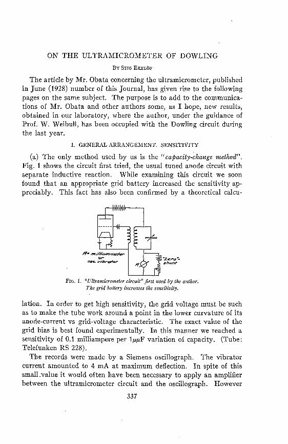
(a) The only method used by us is the "capacity-change method".Fig. 1 shows the circuit first tried, the usual tuned anode circuit withseparate inductive reaction. While examining this circuit we soonfound that an appropriate grid battery increased the sensitivity ap-preciably. This fact has also been confirmed by a theoretical calcu-
FIG. 1. Ultramicrometer circuit" first used by the author.The grid battery increases the sensitivity.
lation. In order to get high sensitivity, the grid voltage must be suchas to make the tube work around a point in the lower curvature of itsanode-current vs grid-voltage characteristic. The exact value of thegrid bias is best found experimentally. In this manner we reached asensitivity of 0.1 milliampere per 1AF variation of capacity. (Tube:Telefunken RS 228).
The records were made by a Siemens oscillograph. The vibratorcurrent amounted to 4 mA at maximum deflection. In spite of thissmall-value it would often have been necessary to apply an amplifierbetween the ultramicrometer circuit and the oscillograph. However
337

[J.O.S.A. & R.S.I., 18
it was found that it was possible to further increase the sensitivity ofthe ultramicrometer circuit.
Using the little amateur transmitting tube just mentioned in thecircuit Fig. 2, we achieved the astonishing result of an anode-currentvariation of 4 milliampere per 1pTF capacity-variation. The principalnovelty shown by Fig. 2 is, that the grid-battery has been replacedby a gridleak condenser combination. An accurate study shows further-more, that the arrangement is influenced in the least possible way bystray capacities, such as may be introduced by the body of the experi-menter. On this account it is not necessary to shield the entire appara-tus. It is sufficient to place the condensers in shielded and groundedboxes.
c**,
1
FIG. 2. A circuit with grid leak and grid condenser, giving asensitivity of 4 mA per uuF capacity variation.
The choice of a suitable tube seems to be of the greatest importancefor the good functioning of the gridleak circuit. Different tubes havebeen tried. Most of them however gave unsteady curves with suddenjumps. The tube giving the sensitivity mentioned has the followingdata: "Telefunken RS 228; 5 w. amateur transmitting valve."
Filament current If = 1.1 amps.Plate voltage Ea = 220 voltsSaturation current s = 200 milliamps.Internal resistance Ri = 3500 ohmsAmplification factor u =6.5
The values of gridleak and condenser should be determined empiri-cally. A small gridleak decreases the sensitivity; too large a leak givesunstable curves. Five thousand ohms is a proper value. The grid con-denser should be chosen rather small, usually < 100/uqiF. Small capacityvariations of this condenser will also influence the anode current, so that
338 STIG EKEL6F
Apr., 1929] ON THE ULTRAMICROMETER OF DOWLING
it is possible to obtain a high sensitivity by measuring these variations.We have never tried this mode however.
As to other data, the following may be mentioned: The frequencyof the tuned circuit is in the order of 500 kilocycles, the coils are usualhoneycomb coils.
(b) One can easily calculate, that with a sensitivity of 4 mA per,uF and the aid of a good galvanometer, it would be possible to measure
without difficulty a displacement of 10-9 mm, i.e. about 1/100 of thediameter of the hydrogen atom! Now, naturally, there is no sense inspeaking of such small mechanical displacements. We must also fullyagree with Mr. Obata in pointing out that the difficulty of maintainingthe anode current constant for a longer time limits the possibility ofsuch extreme measurements.
This is especially the case with the tube used by us, because itsfilament current is very small in comparison with the saturation current.Extremely small variations of the filament current If, therefore, havea considerable influence on the anode current Ia. The author has found,that if an instrument of max. 0.1 mA is used for measuring the vari-ations of a, the I,, should not vary more than 1/50000. It is hardlypossible to reach such extreme constancy, but with the aid of large-capacity batteries and taking other precautions it is not difficult to usean instrument of max. 0.5 mA. With two condenser plates 40 mm inradius, placed 0.1 mm from one another, this would allow us to measuredisplacements less than 10-6 mm.
We have however not yet made use of such extreme measurements.The advantage of the ultramicrometer in engineering lies more in itsapplications to measurements of minute vibrations than of small finitedisplacements.
2. APPLICATIONS
Concerning applications, we have used the Dowling circuit for theexamination of small, rapidly varying pressures and mechanical vibra-tions of different kinds. By recording, for instance, the vibrations of amotor shaft initiated by the blow of a hammer, one has a simple meansof determining the critical speed with regard to bending vibrations.
In the following we shall describe an application of special interest,because it was made in order to solve a problem met with in engineeringpractice. The investigation was performed in one of the hydroelectricplants of the Swedish Government. The problem was as follows:
Before the water reaches the. turbines, it passes racks, which protect
339

[J.O.S.A. & R.S.I., 18
the water wheels from ice. The design of the racks concerned is shownin Fig. 3. They consist essentially of long steel bars or lamels A (cross-section 15 X220 mm), onto which are welded transversal bars C. Itsoon appeared that the lamels broke as shown by Fig. 3; e. g. at theplaces where they are united with the transversal bars. These crackswere explained as coming from fatigue of the material, caused byvibrations of the lamels. In order to confirm this hypothesis it wasnecessary to measure the vibrations and this was made with theultramicrometer. The difficulty of making such measurements at adepth of 6 m below the surface of water was that no fixed point was
C SC
290 C,'cA-H'ere she co mb)eW. aros fos/eOee
FIG. 3. Racks upon which vibration tests were made.
available in the vicinity of the lamels. Where could we obtain a fixedpoint? The following solution was found:
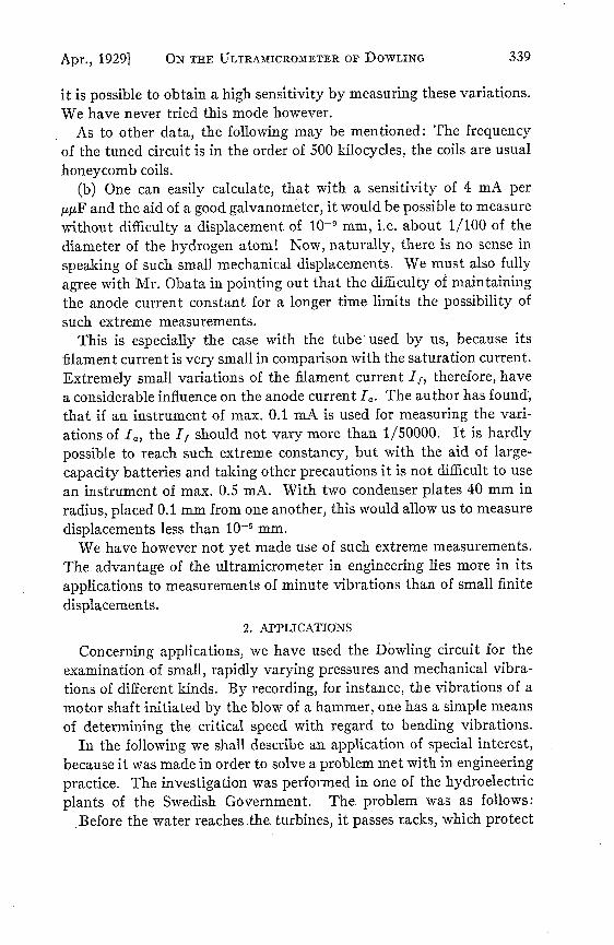
The condenser, the capacity variations of which indicated the vibra-tions of the lamels, was designed according to Fig. 4. A is a brass box,on the bottom of which is placed an insulating disk B. On B is as-sembled the brass disk C, constituting the one plate of the condenser.C is electrically connected to the other parts of the measuring deviceby means of the cable D. The second plate is formed by the disk E,supported by the spring F (C and E are 50 mm in diameter). The airgap between C and E can be regulated by the screws G. The box ismade watertight by the cover H.
Now let the box be fastened to the point of the lamel, where thevibrations are to be measured. We suppose that the free oscillations
340 STIG EELO5F
ON THE ULTRAMICROMETER OF DOWLING
of the disk E and the spring F have a frequency much lower (say 5 X)than that of the lamel vibrations. Under such circumstances E willnot be able to follow the vibrations of the lamel and the other partsof the box; the air gap between C and E will vary according to thelamel vibrations. In the movable part E we have found our fixed point!
, * S .
FIG. 4. Condenser, used for measuring the vibrations of the racks, Fig. 3.
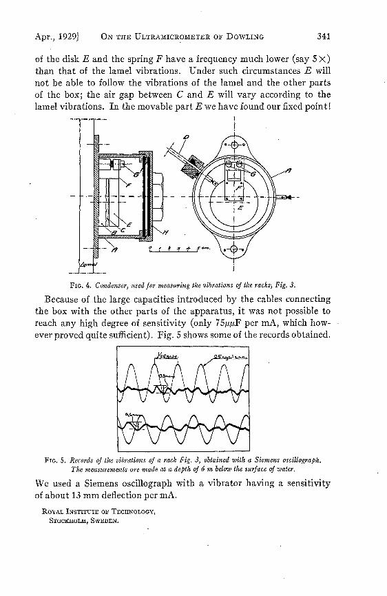
Because of the large capacities introduced by the cables connectingthe box with the other parts of the apparatus, it was not possible toreach any high degree of sensitivity (only 75p/iF per mA, which how-ever proved quite sufficient). Fig. 5 shows some of the records obtained.
FIG. 5. Records of the vibrations of a rack Fig. 3, obtained with a Siemens oscillograph.The measurements are made at a depth of 6 m below the surface of water.
We used a Siemens oscillograph with a vibrator having a sensitivityof about 13 mm deflection per mA.
ROYAL INSTITUTE OF TECHNOLOGY,
STOCKHOLM, SWEDEN.
Apr., 1929] 341