on the relevance of analytical film thickness ehd
TRANSCRIPT

Friction 4(4): 369–379 (2016) ISSN 2223-7690 DOI 10.1007/s40544-016-0133-7 CN 10-1237/TH
RESEARCH ARTICLE
On the relevance of analytical film thickness EHD equations for isothermal point contacts: Qualitative or quantitative predictions?
Jean-David WHEELER, Philippe VERGNE*, Nicolas FILLOT, David PHILIPPON
Univ Lyon, INSA Lyon, CNRS, LaMCoS-UMR5259, Villeurbanne F-69621, France
Received: 04 November 2016 / Revised: 19 November 2016 / Accepted: 20 November 2016
© The author(s) 2016. This article is published with open access at Springerlink.com
Abstract: Thin film and elastohydrodynamic lubrication regimes are rather young domains of tribology and
they are still facing unresolved issues. As they rely upon a full separation of the moving surfaces by a thin (or
very thin) fluid film, the knowledge of its thickness is of paramount importance, as for instance to developing
lubricated mechanisms with long lasting and efficient designs. As a consequence, a large collection of formulae
for point contacts have been proposed in the last 40 years. However, their accuracy and validity have rarely
been investigated. The purpose of this paper is to offer an evaluation of the most widespread analytical
formulae and to define whether they can be used as qualitative or quantitative predictions. The methodology is
based on comparisons with a numerical model for two configurations, circular and elliptical, considering both
central and minimum film thicknesses.
Keywords: thin film lubrication; elastohydrodynamic lubrication (EHL); film thickness prediction; EHD analytical
equation; central film thickness; minimum film thickness; circular contacts; elliptical contacts
1 Introduction
For almost four decades, semi-analytical expressions
(simply named analytical in the following) were pro-
posed to calculate film thickness in elastohydrodynamic
lubrication (EHL) and especially for point contacts.
They generally aimed to predict central and minimum
film thicknesses (hc and hm) in elastohydrodynamic
(EHD) circular contacts under pure rolling and
isothermal conditions, and for lubricants considered
as Newtonian fluids. Numerous formulas have been
published, in particular during the last two decades
during which progress in both experimental and com-
putational techniques was substantial. They have been
widely used by researchers to advance the knowledge
in the fields of thin film lubrication and EHL, and by
design and development engineers for estimating film
thickness in mechanical devices, like gearboxes, rolling
element bearings, cam-tappet assemblies, piston-ring-
liner systems, etc.
Surprisingly, the accuracy of the existing film
thickness relationships has rarely been investigated in
detail, and their application within the conditions for
which they were originally established was not often
verified nor respected. To the best of the authors’
knowledge, very few—if not any—papers have dealt
with these concerns. Except maybe those of van Leeuwen
[1, 2] of whom it was not the primary objective: his aim
was to derive the most accurate values of viscosity-
pressure coefficients from, on one side, central film
thickness measurements performed in circular contacts
and, on the other side, a wide collection of EHD film
thickness equations. Though indirectly, he showed
that certain expressions were more relevant than others
through their ability to provide correct values of
viscosity-pressure coefficients. This is, however, a
typical illustration of the classical approach of EHL,
in which the author has chosen to derive the lubricants’
properties from film thickness or friction measurements
instead of relying on direct rheological measurements,
obtained independently of tribological tests.
* Corresponding author: Philippe VERGNE. E-mail: [email protected]

370 Friction 4(4): 369–379 (2016)
Nomenclature
a contact length or dimension in the
entrainment direction (m)
b contact width or dimension perpendicular
to the entrainment direction (m)
D ratio of reduced radii of curvature,
/x y
D R R
E1, E2 Young modulii of solids 1 and 2 (Pa)
E′ reduced modulus of elasticity (Pa)
2 2
1 1 2 22 / (1 ) / (1 ) /E E E
G dimensionless material parameter
(Hamrock & Dowson) * ·E
hc central film thickness (m)
hm minimum film thickness (m)
k ellipticity ratio b
a
L dimensionless material parameter
(Moes) 0.25·(2 )G U
M dimensionless load parameter (Moes) for
point contact 0.75/ (2 )W U
pH Hertzian pressure (MPa)
Rx reduced radius of curvature in the
entrainment direction (m)
Ry reduced radius of curvature perpendicular
to the entrainment direction (m)
T0 inlet temperature (K)
ue mean entrainment velocity
(m/s) 1 2
( ) / 2u u
u1, u2 velocity in the x-direction of surfaces
1 and 2 (m/s)
U dimensionless speed parameter
(Hamrock & Dowson) · / ( )e x
u E R
w normal load (N)
W dimensionless load parameter
(Hamrock & Dowson) 2/ ( )x
w E R
α* reciprocal asymptotic isoviscous pressure,
according to Blok [21] (Pa−1)
μ lubricant dynamic viscosity (Pa·s)
μ0 lubricant dynamic viscosity (Pa·s) at the
inlet temperature 0
T
ρ0 lubricant density (kg·m−3) at the inlet
temperature 0
T
σ composite roughness of the mating
surfaces (m)
Given the current trends towards more and more
severe conditions applied to lubricated mechanisms
due to technological, economic, and environmental
constraints, and the unceasing film thickness decrease
in lubricated contacts, the need to predict film thickness
with high precision appears more than ever well
founded. Specifically, new important questions have
emerged and require clarification and verification, as
for instance:
(1) a deviation of 10 or 20 nm, which seemed neg-
ligible 40 years ago, can nowadays have some dramatic
consequences on the integrity of the mechanisms: this
justifies the assessment of the analytical equations
currently in use to make sure they are accurate
enough;
(2) the relevance of the extrapolation to often much
lower thicknesses as those used to design the analytical
expressions should be checked to consider the latter
appropriate for predicting very thin film thicknesses.
Furthermore, the related literature generally deals
with central film thickness, hc, whereas it is well known
that hm, the minimum film thickness, is the crucial
parameter for determining the lubrication regime
through the m/h ratio, being the composite
roughness of the mating surfaces. Finally, in many
applications the actual geometry of the contacting
bodies leads to elliptical point contacts. These latter
can be narrow (i.e., slender configuration) or wide,
according to the orientation of the larger equivalent
radius of curvature of the mating bodies with respect
to the main rolling direction. Elliptical point contacts
have received much less attention compared to circular
ones and, as a consequence, a limited number of
analytical expressions were published for the former.
Therefore, the aim of this work is to provide a new
insight into the validity and accuracy of some among
the most widely used analytical film thickness equations,
established for circular and elliptical contacts. From a
set of operating parameters leading to 5 reference cases,
they will be confronted to a full EHD numerical
model, taken here as a reference due to the numerous
conditions considered for achieving its validation against

Friction 4(4): 369–379 (2016) 371
experimentation. Both the central and minimum film
thicknesses will be studied in the case of a Newtonian
lubricant operated under pure rolling and isothermal
conditions. The purpose of this comparison is indeed
not to rank the models against each other, but to
evidence whether they can be considered sufficiently
quantitative or just qualitative, in the domains
investigated in this work.
2 Models and conditions
The choice of a reasonable number of EHD film
thickness equations to be included in this work was
dictated by different criteria (extensive use, circular
and/or elliptical geometry). The widely-used expressions
mentioned below were selected on the basis of (i) van
Leeuwen studies [1, 2] and (ii) a previous experimental
work [3] in which the capabilities of some of them
were quantitatively compared with measurements
performed over wide ranges of operating conditions
and for numerous lubricants of different nature:
(1) Hamrock & Dowson [4], for circular and elliptical
(wide only) contacts;
(2) Nijenbanning et al. [5] for hc in circular and
elliptical (wide only) contacts, combined with Chevalier
c m/h h table [6] for calculating hm (see Ref. [3]) in
circular contacts;
(3) Evans & Snidle [7], for circular contacts only;
(4) Chittenden et al. [8], for circular and elliptical
(slender and wide) contacts;
(5) Masjedi & Khonsari [9], for circular and elliptical
(wide only) contacts.
The analytical expressions and the numerical tables
corresponding to these EHD film thickness equations
and c m/h h ratios are given in Appendix.
Figure 1 provides a schematic description of the
domains on which the analytical models above were
established, as a function of M and L, the dimensionless
load and material parameters as proposed originally by
Moes [10] (M and L are defined in the Nomenclature).
These ranges take into account the indirect (M, L)
variations produced when considering elliptical
contacts, except in the case of the Evans & Snidle
equation which concerns circular cases only. Overall,
the domains of validity of the analytical models,
expressed in a (M, L) chart in Fig. 1, cover well the full
range of EHL. However some of them were restricted
Fig. 1 Domains (expressed by empty rectangles) on which EHD film thickness equations for circular and elliptical contacts were established. The yellowed area represents the common area covered by all the analytical expressions considered here. The black bold dotted line indicates the region where the full numerical model was applied in Ref. [11]. The symbols show the domain corresponding to the 5 references cases of Table 1, in the circular (k = 1) and the elliptical configurations (k = 2.92 or 0.34).
to rather limited (M, L) areas and extrapolation could
result in inaccurate results. There is a common area
covered by all analytical models, given that Chittenden
et al. [8] have also incorporated the results of Hamrock
& Dowson [4] to derive their equations. This overlap
extends to values of M and L between 25 and 45, and
between 5 and 6, respectively, see the yellowed rectangle
in Fig. 1. This area ultimately represents a very narrow
domain compared to the full field of EHL.
The versatile EHD model used here as a reference
has been already presented in Ref. [11] and will not
be detailed further. It results from recent modeling
developments performed at LaMCoS, after the works
of Doki-Thonon in the case of spinning EHD contacts
[12, 13] and those of Habchi who has laid the founda-
tions inherent to this multiphysics model [14, 15].
The steady state problem concerns smooth surfaces,
fully flooded, Newtonian and isothermal conditions.
Based on the finite element method, the numerical
model solves simultaneously the Reynolds, the solids
deformation and the load balance equations. Typically,
the Reynolds equation was solved using 2×10⁴ degrees
of freedom and the convergence was achieved when
a relative deviation lower than 10−3 was obtained.
The physical behavior of the lubricant is taken
into account through (i) a rheological equation which
describes the viscosity changes with pressure and (ii)

372 Friction 4(4): 369–379 (2016)
a classical equation of state for the density variations:
the Newtonian viscosity follows a modified Williams-
Landel-Ferry (WLF) correlation [16] and the density
varies according to the Murnaghan [17] equation. Both
constitutive equations were fitted to independent
characterizations carried out with high pressure
devices, see Ref. [11] for more details.
Since its early developments, quantitative com-
parisons with experiment have proven the reliability
and accuracy of this numerical model to predict film
thickness in various configurations: for instance
with conventional (mineral turbine oil [14]) and non-
conventional lubricants (low viscosity working fluids
or glycerol [18, 19]), or under complex kinematic
conditions (spinning-skewing EHD contacts [13]).
More recently, it was adapted for non-circular EHD
contacts and successfully validated by quantitative
confrontation with experiments [20].
A first reference case (called Case 3) was defined
in the circular configuration, with Rx = Ry = 80 nm, an
entrainment velocity ue = 2 m/s, a normal load w =
800 N, a bearing steel material for the two solids (E =
210 GPa, v = 0.3), and an inlet lubricant temperature
T0 = 313 K, giving α* = 20 GPa–1, μ0 = 0.008 Pa·s and
ρ0 = 863 kg·m–3. Then both the entrainment velocity,
ue, and the normal load, w, were varied in order to
define 4 other reference cases to cover sufficient wide
ranges of operating conditions, see Table 1 where
they are also reported and expressed by the (M, L)
dimensionless parameters. Apart from the central
Case 3 already described, a low (120 N) and a high
(2,500 N) normal load condition together with a low
(0.5 m/s) and a high (10 m/s) entrainment speed
condition are proposed. From these physical values, it is
possible to compute the corresponding dimensionless
Table 1 Normal load, entrainment velocity (both in bold) and Hertzian contact pressure for the circular configuration (in italic) of the five reference cases. The (M, L) values are given under the Case number.
ue (m/s)
0.5 2 10
120 364
— Case 1 (51, 5.2)
—
800 686
Case 2 (962, 3.7)
Case 3 (340, 5.2)
Case 4(102, 7.8)
w (N) Ph (MPa)
2500 1002
— Case 5 (1,062, 5.2)
—
parameters M and L, and to compare them with those
of Fig. 1 for the analytical models.
In the circular configuration, the 5 reference cases
of Table 1 lead to a domain defined by M [50, 1,062]
and L [3.7, 7.8], see the red dots in Fig. 1. Moreover
in Ref. [11], the numerical experimentations covered
a larger range delimited by M [10, 4,000] and L
[2.5, 10], highlighted by the black dotted contour in
Fig. 1 which shows a rather large overlap with the areas
from which the analytical expressions were drawn.
This enables to study and compare the dependence,
for all the models considered here including the full
EHD solution, of w and ue on film thickness for both
configurations, circular firstly, and then elliptical.
The last important point to consider for conducting
an objective analysis concerns the integration of the
lubricant properties. Indeed, the numerical model
used in this work includes two physical laws that
quantitatively describe the actual response of the
lubricant subjected to contact conditions, while the
analytical EHD models are based on empirical
expressions, like the Barus, Roelands or Dowson-
Higginson equations. Concerning the viscosity-pressure
dependence, it should be reminded that Hamrock &
Dowson [4] were aware of the weakness of the Barus
law. In their expressions they preferred to consider α*,
the reciprocal asymptotic isoviscous pressure as pro-
posed by Blok [21], instead of the classical secant
pressure-viscosity coefficient based on an exponential
dependence, i.e., on the so-called Barus law. Interestingly,
the use of α* some decades later has confirmed [22, 3],
by comparison with experiments, that this parameter
was really relevant to predict film thickness. Following
this agreement, the reciprocal asymptotic isoviscous
pressure was used to calculate film thickness from
the analytical expressions.
3 Results and discussion on circular
contacts
Results are expressed as the relative film thickness
deviation given by each analytical equation to our
numerical model (noted ref
h thereafter), a positive
value meaning an overestimation:
ref mod ref ref/ ( )/h h h h h (1)
where h can be either hc or hm, and mod
h refers to a

Friction 4(4): 369–379 (2016) 373
prediction by an analytical model, i.e., Masjedi &
Khonsari [9], Chittenden et al. [8], Evans & Snidle [7],
Hamrock & Dowson [4], Nijenbanning et al. [5] or
Chevalier [6] expressions. Throughout the rest of the
paper, results are graphically reported according the
following order: Case 1, Case 3, Case 5, Case 2, and
Case 4. This enables first to assess and compare the
influence of an increasing normal load (120, 800, and
2,500 N, respectively Case 1, Case 3 and Case 5), the
remaining parameters being kept constant, and then
to pursue the analysis to the entrainment speed
influence (from 0.5 to 10 m/s), respectively for Case 2
and Case 4, w being constant and equal to 800 N.
Figure 2 presents a comparison of the central film
thickness results, expressed by c c,ref/h h , given by the
analytical film thickness equations mentioned before
which are suitable for circular contacts. The 5 models
are, in average, rather accurate and capable to
estimate hc with an acceptable precision (represented
by a bold dotted line in Fig. 2) of 9% in average with
a standard deviation of 6%: the interval of confidence
(defined by +/− the standard deviation to the mean
gap) is delimited by two thin dotted lines in Fig. 2.
The results are not uniform across the models: those
computed from the equation of Chittenden et al. [8]
are in excellent agreement (within 3%) with the
numerical solutions for the 5 reference cases, whereas
the models of Evans & Snidle [7] (in particular at
high load and/or low velocity) and of Nijenbanning
et al. [5] (in a rather uniform manner) deviate more
Fig. 2 Relative deviations given by analytical EHD film thickness expressions on hc, the central film thickness, for the 5 circular reference cases defined in Table 1.
significantly. A general and clear trend is however
revealed, for the conditions simulated in this study:
all the analytical EHD equations overestimate the
central film thickness, on average by 9% which can be
considered nevertheless as a moderate discrepancy.
The relative deviations on minimum film thickness
predictions are reported in Fig. 3, expressed in the
same way as in Fig. 2. For hm, the discrepancy is
much larger than for hc and reaches an average value
of 37% for the 5 reference cases of Table 1, with a
standard deviation of 34%. Nevertheless, the combined
Nijenbanning & Chevalier model [3, 5] provides a
rather fair prediction of hm with a mean overestimation
of +11%, while the use of Evans & Snidle expression
results in the unique, but very low, underestimation
for Case 4, of −1.2%. The three other analytical equations
predict strongly optimistic minimum film thicknesses:
they overestimate hm by nearly +50% with several
occurrences exceeding +80%, especially at high load
and/or low velocity conditions. These deviations are
certainly too large—if not unacceptable—to insure safe
working conditions of lubricated mechanisms, given
the current technical and environmental demands that
lead to lubricate with thinner and thinner lubricating
films. Moreover, they could lead to erroneous
lubrication regime estimation, the actual minimum
film thickness being half-value of the analytically
calculated ones.
In summary, the analytical EHD equations generally
overestimate film thickness in circular contacts, to a
Fig. 3 Relative deviations given by analytical EHD film thickness expressions on hm, the minimum film thickness, for the 5 circular reference cases defined in Table 1.
374 Friction 4(4): 369–379 (2016)
much larger extent for hm, the minimum value, while
the prediction appears acceptable, for an engineering
point of view, for hc, the central film thickness. This
global discrepancy cannot be, to first order, attributed
to the different manners of taking into account the
physical properties of the lubricant in the full numerical
model. If such were the cases, the agreement on hm
may have been more satisfying, given that minimum
film thickness takes place where the pressure approaches
its ambient value and therefore where the density
and viscosity become closer to the ambient values.
However, it is the opposite trend that is observed.
Clearly, the results of this comparison between
analytical and numerical methodologies are in line
with some previous findings. Concerning central film
thickness, van Leeuwen [1, 2] concluded that for both
moderately-loaded and highly-loaded EHD contacts,
Chittenden et al. [8] formula was the more accurate
and that its validity transcended the area where it
was originally designed for. As for minimum film
thickness, the use of Chevalier ratios [6] combined
with the Nijenbanning et al. [5] formula has shown,
from experimental confrontation, to be the more con-
sistent over very wide ranges of the (M, L) parameters
[3]. But perhaps the crucial point to emphasize here
lies in the fact that the results of the previous works
were based on experimental measurements and are
now fully confirmed by the current study which
relies on a purely numerical and modeling approach.
4 Results and discussion on elliptical
contacts
The consideration of elliptical contacts excludes the
Evans & Snidle equations and the Chevalier table, all
designed for the circular geometry. Moreover, there
are two options to represent ellipticity, the first one
based on b
ka
where a is the contact length and b its
width, the second relies on D, which expresses the
ratio of the reduced radii of curvature at the contact
center. k was selected here, given that most of the
works on elliptical contacts have used this parameter
to represent ellipticity.
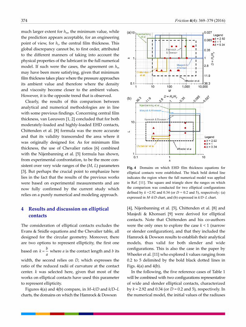
Figures 4(a) and 4(b) compare, in M–k/D and k/D–L charts, the domains on which the Hamrock & Dowson
Fig. 4 Domains on which EHD film thickness equations for elliptical contacts were established. The black bold dotted line indicates the region where the full numerical model was applied in Ref. [11]. The square and triangle show the ranges on which the comparison was conducted for two elliptical configurations defined by k =2.92 and 0.34 (or D = 0.2 and 5), respectively: (a) expressed in M–k/D chart, and (b) expressed in k/D–L chart.
[4], Nijenbanning et al. [5], Chittenden et al. [8] and
Masjedi & Khonsari [9] were derived for elliptical
contacts. Note that Chittenden and his co-authors
were the only ones to explore the case k < 1 (narrow
or slender configuration), and that they included the
Hamrock & Dowson results to establish their analytical
models, thus valid for both slender and wide
configurations. This is also the case in the paper by
Wheeler et al. [11] who explored k values ranging from
0.2 to 5 delimited by the bold black dotted lines in
Figs. 4(a) and 4(b).
In the following, the five reference cases of Table 1
will be combined with two configurations representative
of wide and slender elliptical contacts, characterized
by k = 2.92 and 0.34 (or D = 0.2 and 5), respectively. In
the numerical model, the initial values of the radiuses

Friction 4(4): 369–379 (2016) 375
of curvature along the main axes were varied, keeping
all the remaining parameters constant. As a conse-
quence, the ranges of dimensionless parameters have
been much extended compared to the circular cases
and cover M [131, 2,736], L [4.5, 9.6] and M
[17,358], L [3, 6.4], respectively. This is also visible
in Figs. 4(a) and 4(b) where the values corresponding
to the circular configuration (red dots) are exceeded
for the elliptical cases in M and L, towards lower and
higher extrema.
4.1 Wide elliptical contacts: k = 2.92
First note that Chittenden et al. [8], Hamrock &
Dowson [4], and Nijenbanning et al. [5] formulae
were extrapolated from the domains in M they were
established for reference Case 2 (low speed, medium
load, M = 2,476) and Case 5 (medium speed, high load,
M = 2,736), see Fig. 4(a). However the results for these
particular cases do not show significant differences
with those calculated under regular conditions, i.e.,
without extrapolation, see Fig. 5 for the central film
thickness for instance. In some ways, these results
demonstrate the relative robustness of the 3 models
mentioned just above.
The results are expressed as before for circular
contacts, using Eq. (1). Overall, the confrontation
between analytical film thickness expressions and the
full EHD model for wide elliptical contacts results
in similar trends as for the circular case: firstly hc is
systematically overestimated (see Fig. 5) and secondly,
Fig. 5 Relative deviations given by analytical EHD film thickness expressions on hc, the central film thickness, for the 5 wide elliptical reference cases defined by k = 2.92.
a mean discrepancy of +12% is found, with a standard
deviation of 5%. In a logical way, the Masjedi &
Khonsari model [9] proves to be the most accurate
in predicting central thickness (within 5%) in wide
elliptical contacts (k = 2.92 or D = 0.2). This is the most
recent model (published in 2015), thus one can
reasonably expect a fairer prediction compared with
earlier models. Moreover, it has been established
over the widest area in M [5, 10,000] and for k values
ranging from 1 up to 8: it was thus applied within
its domain of validity and any extrapolation was
introduced which might have resulted in some further
deviation.
When it comes to hm, the same remark as for the
central film thickness applies on the domains of
validity of the analytical expressions, but here it was
not possible to extrapolate the Nijenbanning et al.
model because the tabulated ratio c m/h h at M > 1,000 has not been quantified in Ref. [5]. Thus results for
Case 2 and Case 5 are missing for this expression.
The minimum film thickness results for k = 2.92 are
plotted in Fig. 6.
The minimum film thickness predictions by the
analytical equations always lead to overestimation,
and appear of a satisfying precision: the mean
discrepancy is equal to +6%, and the standard deviation
of the same value. The Nijenbanning et al. [5] table
gives the more accurate estimate of hm, but is limited
up to M = 1,000, thus to Cases 1, 3 and 4 only in this
study. Compared to the circular case, the fact that the
Fig. 6 Relative deviations given by analytical EHD film thickness expressions on hm, the minimum film thickness, for 5 wide elliptical reference cases defined by k = 2.92.

376 Friction 4(4): 369–379 (2016)
analytical models appear more accurate, or less false
in the perspective of a quantitative approach, in the
elliptical configuration may seem surprising. However,
in this section film thicknesses have been computed
for k = 2.92 which still denotes a rather marked wide
elliptical configuration. Under these circumstances,
hydrodynamic effects are largely dominated by
Poiseuille flows in the entrainment speed direction,
the contact approaches the infinitely wide case and
the places where the minimum film thickness occurs
deviate from the lateral lobes towards the contact exit
area [11]. For instance, with k = 2.92 and W = 800 N
(the medium load case) one reaches the equality
between the classical minimum thicknesses found on
the lobes and the film thickness at the center of the
exit zone of the contact [11], where the minima would
occur if k was increased further, as in the case of line
contacts. Here, for k = 2.92 the average c m/h h ratio
obtained from all models (analytical and numerical)
is equal to 1.28 (+28%), against 2.5 (+150%) in the
circular configuration. The hc and hm values becoming
closer, there is no reason why their prediction would
give very different trends, in terms of accuracy.
4.2 Slender elliptical contacts: k = 0.34
In this configuration, the only available analytical
model is that of Chittenden et al. [8]. However, even
if the authors have specifically explored k [0.3, 1],
its range of application in terms of (M, L) domain was
defined for M [20, 70] and L[3, 3.5] (see Fig. 1),
which is rather limited compared with the domain
explored here ( M [17, 358], L [3, 6.4]), see Figs. 4(a)
and 4(b). This model was thus significantly extrapolated
for most cases to obtain the results reported in Fig. 7.
For the first time in this work, central film thickness
is underestimated (see Fig. 7 left) with a mean relative
gap of −20% and a standard deviation of 9%: these
values are rather similar to those reported concerning
hc prediction in the circular and wide elliptical cases.
In contrast, the minimum thickness is dramatically
overestimated with an average relative difference of
the order of 140%. This tendency clearly shows that
the Chittenden et al. [8] model has no capability to
properly capture the underlying mechanisms occurring
in slender elliptical contacts when extrapolated to
rather high M values. Two main phenomena intervene
in such conditions. The hydrodynamics effects are
dominated by the lateral Poiseuille flow rates along
the directions transverse to the entrainment velocity
[11]. In the meantime a relatively larger radius of
curvature in the ue direction reduces the wedge effect
and thus the film building ability. The two effects are
cumulative to generate a dramatic film thickness
reduction especially on hm, which leads to unusual
c m/h h ratios. For the 5 reference cases considered here,
this ratio is equal to 6.2 in average, which is a much
larger value than in the circular or wide configurations.
Furthermore, it can take values close to or higher
than 9, as for the reference Case 2 and Case 5 where
the minimum film thickness calculated from the full
Fig. 7 Relative deviations given by the Chittenden et al. [8] analytical formulae on hc (left) and hm (right) for the 5 elliptical reference cases in a slender configuration defined by k = 0.34.

Friction 4(4): 369–379 (2016) 377
EHD model drops down to 13 and 28 nm, respectively.
This underlines the impossibility, for the slender
configuration, to extrapolate the Chittenden et al. [8]
model to M values outside the range the expression
was designed for.
5 Conclusions
Thin film lubrication and EHL are rather young
domains of tribology and of science and technology
in general, which really emerged about 70 years ago.
One could have think, with the tremendous deve-
lopment of experimental techniques and computational
tools, that they could become mature and well
understood after this period. That was somehow one
of the very first objectives of this work to ensure that
one is able to predict analytically the lubricant film
thickness in point contacts operated under the simplest
conditions (Newtonian fluid, smooth surfaces, and no
thermal effect).
Based upon a selection of well-known and widely
used semi-analytical expressions, the first step consisted
to present and compare their domains of validity,
expressed through the M, L and k (or D) parameters.
The differences among the models and the ranges not
covered—or covered by only some of the formulae—
have been identified and highlighted, especially
when extrapolations were required to be carry out.
The comparison between the analytical predictions
and the results from a full EHD solver has been then
examined for circular contacts. In spite of being the
most studied configuration from the earlier stages
of development of thin film lubrication and EHL, this
first assessment showed that film thickness was
systematically overevaluated: the central film thickness
was rather accurately predicted whereas a much larger
discrepancy was obtained on the minimum film
thickness.
The extension to elliptical cases, both slender and
wide, was conducted with a more limited number of
analytical models. The comparison was found to be
more favorable in the case of wide elliptical contacts:
film thick thickness was still over estimated but in a
lower extent, and especially for the minimum film
thickness where the best agreement between analytical
and numerical predictions was obtained. In contrast,
the worst situation was pointed out in the case of
slender contacts, for which only one analytical model
was studied and showed its quasi inability for
extrapolation to larger M values than those it was
derived for.
Whatever the geometrical configuration, circular or
elliptical, it is clear that the reference Case 5 and Case
2, namely the highly loaded and low velocity cases,
gathered the largest discrepancies with the analytical
models. This is certainly a major weakness because
such cases correspond in fact to conditions more and
more frequently found nowadays in lubricated systems:
very thin lubricating films in line with the unceasing
drop of film thickness with time, and heavily loaded
contacts as those found for instance in rolling element
bearings or in gears.
From the results of the current work, it is clear that
analytical models can, at best, provide a qualitative
estimate of film thickness. In such an approach, it
could be recommended to use the Chittenden et al. [8]
equation for estimating hc and the Nijenbanning et al.
expression [5] combined with the Chevalier table [6, 3]
for predicting hm in circular contacts, the Masjedi &
Khonsari models [9] for hc and hm in wide elliptical
contacts. The question of the slender elliptical contacts
remains open, pending a suitable analytical model.
A great care should be taken for establishing the
lubrication regime: all the analytical models investigated
in this work over predict minimum film thickness,
which may lead to estimate erroneous frontiers
between full film and mixed lubrication regimes.
Given the findings of this work and the conclusions
and recommendations reported above, the most reliable
approach to predict film thickness in EHD point
contacts should, in authors’ opinion, rely over a full
numerical model. It is quantitative by nature and
can include the actual lubricant behavior—obtained
independently from tribological tests—and various
other features not accounted for here.
Acknowledgment
This work was partly financed by SKF in the framework
of the global program “Advanced Bearing Lubrication”.

378 Friction 4(4): 369–379 (2016)
Appendix: Analytical expressions
Hamrock & Dowson [4]:
0.640.75(0.67 0.53 0.067 /
c
)2.6/ 9 (1 0.61 )y xR R
xh R U G W e
0.640.70( )0.68 0.49 0.0 3
m
/73.63/ )1( y xR R
xh R U G W e
Evans & Snidle [7]:
0.5 0.026 0.40
c2 1/ ( ( ) .7)
xh R U M L
0.5 0.17 0.34
m/ 2 1.9( ( ) )
xh R U M L
Chittenden et al. [8]:
2/31.23( )0.68 0.49 0. 3
c
/074.3 (1/ )1 y xR R
xh R U G W e
2/30.67( )0.68 0.49 0. 3
m
/073.6 (1/ )8 y xR R
xh R U G W e
Nijenbanning et al. [5]:
0.5 3 / 2 4 4 3 / 8 2 / 3c RI EI 00
8 8 / 8 1/RP EP
( 2 ) (/ ( ( )) ( )
( ) )
sx
s s
h R U H H H
H H
with:
/x y
D R R
EI RI1.2/ /1.5(1 )H Hs e
1
001.8H D
14/15 15/7 1 2
RI145(1 0.796 )H D D M
4 / 7 14 / 15 1/ 15 2 / 15EI 3.18(1 0.006 ln( ) 0.63 )H D D D M
–2/3 2/ 3
RP1.29(1 0.691 )H D L
4/7 7 / 20 1/24 1/12 3/ 4
EP1.48(1 0.006ln( ) 0.63 )H D D D M L
hm is obtained from the hc /hm ratios reported in the
following tables:
M D = 1 from Chevalier
[3, 6] 1 3 10 30 100 300 1000
0 1.2645 1.2635 1.26 1.25 1.33 1.48 1.93
2 1.2915 1.3045 1.35 1.48 1.8 2.23 3.28
5 1.251 1.273 1.35 1.57 1.92 2.42 3.43
10 1.2645 1.2835 1.35 1.54 1.87 2.33 3.2
20 1.2425 1.2575 1.31 1.46 1.72 2.08 2.79
40 1.1985 1.2055 1.23 1.3 1.42 1.58 1.97
L
60 1.1545 1.1535 1.15 1.14 1.12 1.08 1.15
M D = 0.4
5 10 20 50 100 200 500 1000
0 1.3 1.3 1.3 1.3 1.3 1.3 1.3 1.3
1 1.3 1.3 1.3 1.3 1.4 1.4 1.5 1.6
2.5 1.3 1.3 1.3 1.4 1.5 1.6 1.7 1.8
5 1.3 1.3 1.4 1.5 1.5 1.6 1.8 2
10 1.3 1.4 1.4 1.5 1.5 1.6 1.8 2
L
25 — 1.4 1.3 1.5 1.6 1.6 1.7 1.9
M D =0.2
5 10 20 50 100 200 500 1000
0 1.2 1.3 1.3 1.3 1.3 1.3 1.3 1.3
1 1.2 1.3 1.3 1.3 1.3 1.3 1.3 1.4
2.5 1.2 1.3 1.3 1.3 1.3 1.3 1.3 1.4
5 1.2 1.3 1.3 1.3 1.3 1.4 1.4 1.5
10 1.2 1.3 1.3 1.4 1.4 1.4 1.5 1.5
L
25 — 1.3 1.3 1.4 1.4 1.4 1.5 1.5
Masjedi & Khonsari [9]:
0.025 0.064 0.180.663 0.502 0.045 0.74
c 3.672 1 0.573/ ( )k k k kxh R U G W e
0.023 0.045 0.150.711 0.650 0.09 0.676
m / (1.637 1 0.974 )k k k kxh R U G W e
Open Access: The articles published in this journal
are distributed under the terms of the Creative
Commons Attribution 4.0 International License (http://
creativecommons.org/licenses/by/4.0/), which permits
unrestricted use, distribution, and reproduction in
any medium, provided you give appropriate credit
to the original author(s) and the source, provide a
link to the Creative Commons license, and indicate if
changes were made.
References
[1] van Leeuwen H. The determination of the pressure–
viscosity coefficient of a lubricant through an accurate film
thickness formula and accurate film thickness measurements.
Proc IMechE, Part J: J Eng Tribol 223(8): 1143–1163 (2009)
[2] van Leeuwen H. The determination of the pressure–
viscosity coefficient of a lubricant through an accurate film
thickness formula and accurate film thickness measurements.
Part 2: High L values. Proc IMechE, Part J: J Eng Tribol
225(6): 449–464 (2011)
[3] Chaomleffel J P, Dalmaz G, Vergne P. Experimental results
and analytical predictions of EHL film thickness. Tribol Int
40(10-12): 1543–1552 (2007)

Friction 4(4): 369–379 (2016) 379
[4] Hamrock B J, Dowson D. Isothermal elastohydrodynamic
lubrication of point contacts Part III – Fully flooded results.
Trans ASME J Lubr Technol 99(2): 264–276 (1977)
[5] Nijenbanning G, Venner C H, Moes H. Film thickness in
elastohydrodynamically lubricated elliptic contacts. Wear
176: 217–229 (1994)
[6] Chevalier F. Modélisation des conditions d'alimentation
dans les contacts élastohydrodynamiques ponctuels. (in French).
PhD thesis, INSA de Lyon, France, 1996.
[7] Evans P, Snidle R. The isothermal elastohydrodynamic lubrica-
tion of spheres. ASME J Lubr Technol 103: 547–557 (1981)
[8] Chittenden R J, Dowson D, Dunn J F, Taylor C M. A
theoretical analysis of the isothermal elastohydrodynamic
lubrication of concentrated contacts—Part 2: General case,
with lubricant entrainment along either principal axis of the
hertzian contact ellipse or at some intermediate angle. Proc
R Soc London A397: 271–294 (1985)
[9] Masjedi M, Khonsari M M. On the effect of surface roughness
in point-contact EHL: Formulas for film thickness and
asperity load. Tribol Int 82(A): 228–244 (2015)
[10] Moes H. Communication. In Proceedings of the Symposium
on Elastohydrodynamic Lubrication, London, 1965: 244–245.
[11] Wheeler J D, Fillot N, Philippon D, Vergne P, Morales-
Espejel G E. On the crucial role of ellipticity on ehd film
thickness and friction. Proc IMechE, Part J: J Eng Tribol
230(12): 1503–1515 (2016)
[12] Doki-Thonon T, Fillot N, Vergne P, Morales-Espejel G E.
Numerical insight into heat transfer and power losses in
spinning EHL non-Newtonian point contacts. Proc IMechE
Part J: J Eng Tribol 226(1):23–35 (2012)
[13] Doki-Thonon T, Fillot N, Morales Espejel G E, Querry M,
Philippon D, Devaux N, Vergne P. A dual experimental /
numerical approach for film thickness analysis in TEHL
spinning skewing circular contacts. Tribol Lett 50(1): 115–
126 (2013)
[14] Habchi W, Demirci I, Eyheramendy D, Morales-Espejel G E,
Vergne P. A finite element approach of thin film lubrication
in circular EHD contacts. Tribol Int 40(10–12): 1466–1473
(2007)
[15] Habchi W, Eyheramendy D, Vergne P, Morales-Espejel G E.
Stabilized fully-coupled finite elements for elastohydrodynamic
lubrication problems. Adv Eng Softw 46(1): 4–18 (2012)
[16] Bair S, Mary C, Bouscharain N, Vergne P. An improved
Yasutomi correlation for viscosity at high pressure. Proc.
IMechE, Part J: J Eng Tribol 227(9): 1056–1060 (2013)
[17] Murnaghan F D. The compressibility of media under extreme
pressures. Proc Nat Acad Sci 30(9): 244–247 (1944)
[18] Habchi W, Vergne P, Eyheramendy D, Morales-Espejel G
E. Numerical investigation of the use of machinery low
viscosity working fluids as lubricants in EHL point contacts.
Proc IMechE, Part J: J Eng Tribol 225(6): 465–477 (2011)
[19] Habchi W, Matta C, Joly-Pottuz L, De Barros M, Martin
J M, Vergne P. Full film, boundary lubrication and
tribochemistry in steel circular contacts lubricated with
glycerol. Tribol Lett 42(3): 351–358 (2011)
[20] Wheeler J D. Non-elliptical point contacts: The torus-on-
plane conjunction. PhD thesis, INSA Lyon, 2016.
[21] Blok H. Inverse problems in hydrodynamic lubrication
and design directives for lubricated flexible surfaces. In
Proceedings of the International Symposium on Lubrication
and wear, Houston, 1963: 1–151.
[22] Bair S. An experimental verification of the significance of
the reciprocal asymptotic isoviscous pressure for EHD
lubricants. Tribol Trans 36(2): 153–162 (1993)
Jean-David WHEELER. He received
his M.S. from the Université de
Lyon and his Mechanical Engineer
degree from the INSA de Lyon in
2013. Since then, he has joined
the Laboratoire de Mécanique des
Contacts et des Structure (LaMCoS) and has been
involved in tribology research, on the topic of EHL.
In the frame of the SKF program “Advanced Bearing
Lubrication”, his focus is the lubrication of the flange
roller-end contact. His investigations are led by both
experimental and numerical means.
Philippe VERGNE. He is currently
CNRS senior researcher at LaMCoS
INSA-Lyon. He is the academic leader
of the research chair “Lubricated
Interfaces for the Future” funded
by the SKF company. He obtained
a PhD in mechanical engineering and a Doctor of
Science (Habilitation) from INSA-Lyon and University
of Lyon, in 1985 and 2002 respectively.
His research focuses on the rheological & tribological
behavior of lubricants, on the development of
numerical models in the context of EHL & nano scale
lubrication, and of in situ techniques to analyze in
details highly confined thin films.