on the possibility of generalizing the results of studies
TRANSCRIPT
machines
Article
On the Possibility of Generalizing the Results of Studies ofDynamical Systems on the Example of a Vehicle Suspension
Anatoliy Dubrovskiy, Sergei Aliukov * and Konstantin Osintsev
�����������������
Citation: Dubrovskiy, A.; Aliukov, S.;
Osintsev, K. On the Possibility of
Generalizing the Results of Studies of
Dynamical Systems on the Example
of a Vehicle Suspension. Machines
2021, 9, 68. https://doi.org/10.3390/
machines9030068
Received: 3 February 2021
Accepted: 19 March 2021
Published: 22 March 2021
Publisher’s Note: MDPI stays neutral
with regard to jurisdictional claims in
published maps and institutional affil-
iations.
Copyright: © 2021 by the authors.
Licensee MDPI, Basel, Switzerland.
This article is an open access article
distributed under the terms and
conditions of the Creative Commons
Attribution (CC BY) license (https://
creativecommons.org/licenses/by/
4.0/).
Institute of Engineering and Technology, South Ural State University, 76 Prospekt Lenina,454080 Chelyabinsk, Russia; [email protected] (A.D.); [email protected] (K.O.)* Correspondence: [email protected]
Abstract: The dynamics of mechanical systems, the operation of electromagnetic and electronicdevices and devices, the principle of operation of a number of machines and mechanisms, engineer-ing structures from various fields are often described by differential equations and their systems.Differential equations are often mathematical models of the movement and operation of variousengineering objects. As a rule, such equations are solved by numerical methods for specific parametervalues. These methods of solving differential equations are widely used in practice. However, thesemethods also have significant disadvantages. For example, the solution of differential equations isobtained for a specific object with the specified parameters. In this case, a solution is obtained for asingle point in the parameter space of a set of similar objects, points in this space of the consideredfamily of objects. A natural question arises: Is it possible to extend the results of the solution for asingle point in space (a specific object) and the identified properties and regularities to other points(other objects) of the considered family? The purpose of this article is to identify conditions underwhich it is possible to generalize the results of solving differential equations with specific parametervalues describing a single construction to the entire family of similar constructions, the entire spaceof parameters under consideration. The implementation of the identified conditions is illustratedby the example of solving the problem of “analyzing the dynamic properties of a mathematicalmodel of a car with adaptive (adjustable) suspension of a new principle of action (developed by theauthors), moving at a variable speed along an indirect profile of the road surface and developingrecommendations for their radical improvement”.
Keywords: adjustable suspension; differential equations; dynamics; generalization of calculationresults; numerical methods; vehicle
1. Introduction
Currently, when constructing the laws of motion of dynamical systems [1], i.e., whensolving the Cauchy problem (“initial” problem) [2,3] or when constructing a periodicsolution [3] of differential equations of motion of dynamical systems, as a rule, the authorsuse a “numerical” solution. Only one point in the parameter space of the dynamic system isanalyzed. However, at the end of the study, without justifying this in any way, the authorstry to generalize their conclusions to the entire space of parameters of a dynamical system.In general, this is, of course, unacceptable. Such a transition, the transition to “non-localuse of local analysis results”, is possible only if the dynamic system under study has somespecial properties [4].
This problem is well-known [4] and prompts every time the “numerical” constructionof the laws of motion of dynamical systems, which indicates its undoubted relevance.Therefore, we will consider its solution in more detail, using the example of solvingthe problem of “analyzing the dynamic properties of a car moving at a variable speedalong an indirect profile of the road surface and developing recommendations for theirradical improvement”.
Machines 2021, 9, 68. https://doi.org/10.3390/machines9030068 https://www.mdpi.com/journal/machines

Machines 2021, 9, 68 2 of 11
It should be noted that the analysis of dynamic systems, as a rule, begins with thecreation of its design scheme (dynamic model) and the subsequent formation of its math-ematical model-the differential equations of motion of the car and the determination ofthe initial, boundary conditions or periodicity conditions (depending on the problem to besolved). A further process of analysis of dynamic systems, especially highly nonlinear [1],such as, for example, “the car is moving with variable velocity-linear profile of the roadsurface”, begins with the construction of the laws of motion of the vehicle, i.e., integrationof differential equations of motion of car a numerical method.
Pre-note that currently, a group of leading researchers of Automotive Department,South Ural State University, consisting of six professors, doctors of technical Sciences,specialists in the field of automotive industry, completed a series of fundamental workson the creation of adaptive dampers and elastic elements (adaptive suspension vehicles)with a new principle of action. In terms of the combination of functional properties andperformance characteristics, the designs of adaptive suspensions developed by authors ofthis article have significantly surpassed existing analogues. In this regard, in the future,we will assume that the springing system of the car under study is equipped with adaptivesuspensions developed by authors of this article [5].
2. Materials and Methods2.1. Design Scheme of a Car with Adaptive Suspension, Accepted Assumptions
So, let us consider a dynamic model of a front-wheel drive car with adaptive sus-pension [5] moving on a non-straight road surface (Figure 1). By the term “adaptivesuspension”, we mean such a system of springing a car, the performance characteristics ofwhich can be changed during its movement, depending on road conditions.
Machines 2021, 9, x FOR PEER REVIEW 2 of 12
their radical improvement”. It should be noted that the analysis of dynamic systems, as a rule, begins with the
creation of its design scheme (dynamic model) and the subsequent formation of its mathematical model-the differential equations of motion of the car and the determination of the initial, boundary conditions or periodicity conditions (depending on the problem to be solved). A further process of analysis of dynamic systems, especially highly non-linear [1], such as, for example, “the car is moving with variable velocity-linear profile of the road surface”, begins with the construction of the laws of motion of the vehicle, i.e., integration of differential equations of motion of car a numerical method.
Pre-note that currently, a group of leading researchers of Automotive Department, South Ural State University, consisting of six professors, doctors of technical Sciences, specialists in the field of automotive industry, completed a series of fundamental works on the creation of adaptive dampers and elastic elements (adaptive suspension vehicles) with a new principle of action. In terms of the combination of functional properties and performance characteristics, the designs of adaptive suspensions developed by authors of this article have significantly surpassed existing analogues. In this regard, in the future, we will assume that the springing system of the car under study is equipped with adap-tive suspensions developed by authors of this article [5].
2. Materials and Methods 2.1. Design Scheme of a Car with Adaptive Suspension, Accepted Assumptions
So, let us consider a dynamic model of a front-wheel drive car with adaptive sus-pension [5] moving on a non-straight road surface (Figure 1). By the term “adaptive suspension”, we mean such a system of springing a car, the performance characteristics of which can be changed during its movement, depending on road conditions.
Figure 1. Design diagram of a vehicle with adaptive suspension.
Figure 1 shows the following notation: JДВ—flywheel that simulates rotating parts and links of a drive motor; JСЦ—flywheel that simulates the rotating parts of the clutch
Figure 1. Design diagram of a vehicle with adaptive suspension.
Figure 1 shows the following notation: JДB—flywheel that simulates rotating partsand links of a drive motor; JCЦ—flywheel that simulates the rotating parts of the clutchdisc and the drive links of the gearbox attached to it; JКΠ—flywheel that simulates therotating parts of the driven links of the gearbox; JГ—flywheel that simulates rotating partsfrom the synchronizer of the engaged transmission to their car wheels; CΠ1 (fΠ1), CΠ2 (fΠ2)—functional analogs of elastic elements with nonlinear performance characteristics of thefront and rear suspensions, respectively; KΠ1 (fΠ1, u1), KΠ2 (fΠ2, u2) —functional analoguesof adaptive shock absorbers for the front and rear suspensions; fΠ1, fΠ2—the deformation

Machines 2021, 9, 68 3 of 11
of the front and rear suspension, respectively; u1, u2—control actions on the adaptiveshock absorbers of the front and rear suspension, accordingly; CТР1, CТР2, KТР1, KТР2—coefficients of stiffness and damping of the corresponding sections of the transmission;CN
ш1, CNш2, Cφ
ш1, Cφш2—coefficients of normal and angular stiffness of tires wheels of
the front and rear axles, respectively; α—angle of descent (ascent); ϑ—angle of rotationof the sprung mass in the plane XOZ; MΠ—the mass of the sprung; М1, М2—unsprungmasses, front and rear respectively; η1, η2—vertical movements of the correspondingunsprung masses; h1, h2—height of road profile irregularities under the correspondingwheels; Pk—traction force; Pf1, Pf2—rolling resistance forces of the respective wheels; PN1,PN2 —reactions are normal for the wheels; λ1, λ2—the angles of inclination of the normalreactions; PW—the force of air resistance.
The following assumptions are made when creating a dynamic car model:
1. The movement is flat (there is no movement in the transverse plane), the height ofthe road irregularities under the left and right sides is the same and the movementof unsprung masses occurs only perpendicular to the road plane, in the longitudinaldirection along with the sprung mass;
2. We consider passenger cars of the middle class of segment B, up to 4.2 m long;3. Front-wheel drive cars are considered;4. There is no slippage at the point of contact of the wheel with the support surface;5. Energy dissipation in suspension springs and silent blocks is not taken into account;6. Deformation of silent blocks and similar suspension elements is not taken into account.
When developing the dynamic model, the model proposed by the authors V. A.Umnyashkin, N. M. Filkin, and R. S. Muzafarov was used as a basis [6].
2.2. Mathematical Model of a Front-Wheel Drive Vehicle with Adaptive Suspension
Taking into account the accepted assumptions, the dynamical system under study hasten degrees of freedom. Let us write a vector of generalized coordinates:
q = col{
X Z ϑ η1 η2 ϕdv ϕsts ϕkп ϕg ϕk1}
.
here, X—longitudinal movement of the vehicle; Z—vertical movement of the sprung mass;ϑ—angle of rotation of the sprung mass in the plane XOZ; η1, η2—vertical movements ofthe corresponding unsprung masses; ϕдв, ϕсц, ϕкп, ϕг—angles of rotation of parts of thecorresponding sections of the transmission.
It should be noted that the dynamical system under study contains nonholonomicconnections. Therefore, drawing up a mathematical model of car movement based onLagrange equations of the second kind is unacceptable in this case. To create a mathematicalmodel of the motion of the dynamical system under study, we use a special form ofLagrange equations of the second kind—Lagrange equations of the second kind withredundant coordinates [7–9]:
ddt
(∂T∂
.qk
)− ∂T
∂qk+
∂P∂qk
+∂F∂
.qk
= Qk +2
∑i=1
λihik (1)
here, Т—kinetic energy of the system; Π—potential energy of the system; φ—Rayleighdissipative function that characterizes the rate of mechanical energy dissipation; Qk—generalized force, corresponding to the K-th generalized coordinate qk; ′—the differentialoperator in the variable t; λi—Lagrange multiplier [10]; hik—additional Lagrange functions;k ∈ {1, 2, . . . , 12}.
Redundant coordinates are not independent. Therefore, equations connecting redun-dant coordinates with independent generalized coordinates should be added to Equa-tion (1)
dxN1
dt= 0;
dxN2
dt. (2)
Machines 2021, 9, 68 4 of 11
here, dxN1dt , dxN2
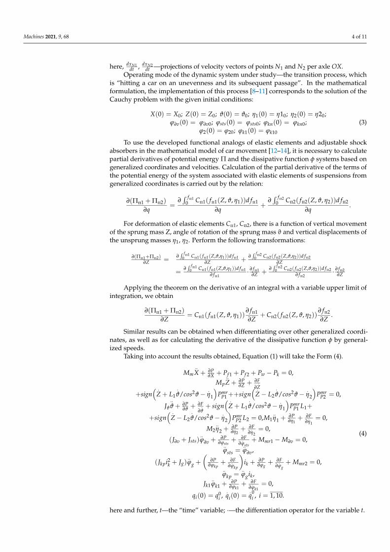
dt —projections of velocity vectors of points N1 and N2 per axle OX.Operating mode of the dynamic system under study—the transition process, which
is “hitting a car on an unevenness and its subsequent passage”. In the mathematicalformulation, the implementation of this process [8–11] corresponds to the solution of theCauchy problem with the given initial conditions:
X(0) = X0; Z(0) = Z0; ϑ(0) = ϑ0; η1(0) = η10; η2(0) = η20;ϕ∂v(0) = ϕ∂v0; ϕsts(0) = ϕsts0; ϕkn(0) = ϕkn0;
ϕ2(0) = ϕ20; ϕk1(0) = ϕk10
(3)
To use the developed functional analogs of elastic elements and adjustable shockabsorbers in the mathematical model of car movement [12–14], it is necessary to calculatepartial derivatives of potential energy Π and the dissipative function φ systems based ongeneralized coordinates and velocities. Calculation of the partial derivative of the terms ofthe potential energy of the system associated with elastic elements of suspensions fromgeneralized coordinates is carried out by the relation:
∂(Πп1 + Πп2)
∂q=
∂∫ fп1
0 Cп1( fп1(Z, ϑ, η1))d fп1
∂q+
∂∫ fп2
0 Cп2( fп2(Z, ϑ, η2))d fп2
∂q.
For deformation of elastic elements Cп1, Cп2, there is a function of vertical movementof the sprung mass Z, angle of rotation of the sprung mass ϑ and vertical displacements ofthe unsprung masses η1, η2. Perform the following transformations:
∂(Πп1+Πп2)∂Z =
∂∫ fп1
0 Cп1( fп1(Z,ϑ,η1))d fп1∂Z +
∂∫ fп2
0 Cп2( fп2(Z,ϑ,η2))d fп2∂Z
=∂∫ fп1
0 Cп1( fп1(Z,ϑ,η1))d fп1∂ fп1
· ∂ fп1∂Z +
∂∫ fп2
0 Cп2( fп2(Z,ϑ,η2))d fп2∂ fп2
· ∂ fп2∂Z
Applying the theorem on the derivative of an integral with a variable upper limit ofintegration, we obtain
∂(Πп1 + Πп2)
∂Z= Cп1( fп1(Z, ϑ, η1))
∂ fп1
∂Z+ Cп2( fп2(Z, ϑ, η2))
∂ fп2
∂Z.
Similar results can be obtained when differentiating over other generalized coordi-nates, as well as for calculating the derivative of the dissipative function φ by general-ized speeds.
Taking into account the results obtained, Equation (1) will take the Form (4).
Mm..X + ∂P
∂X + Pf 1 + Pf 2 + Pw − Pk = 0,Mp
..Z + ∂P
∂Z + ∂F∂
.Z
+sign( .
Z + L1.ϑ/cos2ϑ− .
η1
)Pmr
P1 ++sign( .
Z− L2.ϑ/cos2ϑ− .
η2
)Pmr
P2 = 0,
Jϑ
..ϑ + ∂P
∂ϑ + ∂F∂
.ϑ+ sign
( .Z + L1
.ϑ/cos2ϑ− .
η1
)Pmr
P1 L1+
+sign( .
Z− L2.ϑ/cos2ϑ− .
η2
)Pmr
P2 L2 = 0,M1..η1 +
∂P∂η1
+ ∂F∂
.η1
= 0,
M2..η2 +
∂P∂η2
+ ∂F∂
.η2
= 0,
(J∂v + Jsts)..ϕ∂v +
∂P∂ϕsts
+ ∂F∂
.ϕsts
+ Mmr1 −M∂v = 0,..ϕsts =
..ϕ∂v,
(Jkpi2k + Jg)..ϕg +
(∂P
∂ϕkp+ ∂F
∂.ϕkp
)ik + ∂P
∂ϕg+ ∂F
∂.ϕg
+ Mmr2 = 0,..ϕkp =
..ϕgik,
Jk1..ϕk1 +
∂P∂ϕk1
+ ∂F∂
.ϕk1
= 0,
qi(0) = q0i ,
.qi(0) =
.q0
i , i = 1, 10.
(4)
here and further, t—the “time” variable; ·—the differentiation operator for the variable t.

Machines 2021, 9, 68 5 of 11
Thus, the differential Equation (4), together with the initial conditions (3) and addi-tional Equation (2), represent a mathematical model of the dynamic system under study“the movement of a front-wheel drive car with an adjustable suspension over standardizedindividual irregularities”.
2.3. Some Results of the “Theoretical”, Numerical Analysis of the Dynamical System under Study
As a result of solving the above problem (2), (3), (4), the numerical method can beused to estimate many dynamic parameters of the dynamic system under study, which,unfortunately, are local in nature. Therefore, in particular, we found that with the optimalchoice of parameters of the adaptive suspension of the VW PASSAT CC car when the carpasses through an unevenness:
1. Completely eliminates the phenomenon of wheel separation from the support (from theroadbed), in the entire range of speeds; as a result, the handling of the car improves,and the safety of its movement increases.
2. More than twice, the vertical acceleration of the body and, consequently, the dynamicloads on the driver and passengers are reduced.
3. More than twice, the amplitude of vibrations of the body when driving a car throughan unevenness is reduced due to the use of adaptive suspensions.
2.4. Analysis of Bench Tests of the Dynamic System under Study
It should be noted that the results 1, 2, 3 obtained in the Section 2.2 fully confirmedby experimental studies of cars, in particular, bench tests of the VW PASSAT CC car ona full-scale, stand of the front right quarter of the suspension of the VW PASSAT CC car(Figure 2).
Machines 2021, 9, x FOR PEER REVIEW 6 of 12
Figure 2. Full-scale stand of the front right part of the suspension of the VW PASSAT CC car.
The stand (Figure 2) includes a base 2, on which two symmetrically arranged vertical guides 1 of the movable load 3—a simulator of the “right front quarter” of the VW PASSAT CC car body—are fixed. The lower support 4 (silent block) of the right front suspension arm 5 is fixed to the movable load and and the upper support 6 of the shock strut 8 of the right front wheel 9. The elastic element 7 of the right front wheel is mounted on the shock strut. The composition of the stand also includes adjustable drive motor 10, the gear actuator support of the vibrator 12, 11 gauge “level” right front wheel, the sensor 13 measuring the force acting from the side wheel bearing 9 12 vibrator, 14 gauge measuring “bending the wheel”, the monitor 15 personal computer, recording the measured parameters and the control unit 16 of the degree of dissipation of adaptive suspension and oscillation frequency supports of the vibrator. The sensor 14 actually measures the distance from the center of the wheel 9 to the support 12 of the vibrator, i.e., the “dynamic radius” of the wheel. When the wheel is detached from the support, this sensor also measures the total distance from the center of the wheel to the support of the vibrator. However, in this case the measured value is equal to the sum of “static radius” wheels and a value of “rebound wheels”—the distance between the wheel surface and support. Thus, simulation of the vehicle on uneven, i.e., the simulation of the vertical oscillatory motion of a wheel, carried out by implementing a vertical reciprocating motion of the support 12. Moreover, the speed of movement along the irregularities is modeled by selecting the appropriate oscillation frequency of the support 12 and can be smoothly “changed” by adjusting the speed of the drive motor 10. “The height of the irregularities”, i.e., the oscillation amplitude of the support 12, can be continuously adjusted. However, in our experiments, the “height of the irregularities” was unchanged and was equal to 50 mm. All measurements were recorded on the PC 15, and the control of the frequency of vibrations of the support and of the degree of dissipation of the adaptive shock absorber were carried out using the control complex 16.
Figure 2. Full-scale stand of the front right part of the suspension of the VW PASSAT CC car.
The stand (Figure 2) includes a base 2, on which two symmetrically arranged verticalguides 1 of the movable load 3—a simulator of the “right front quarter” of the VW PASSAT

Machines 2021, 9, 68 6 of 11
CC car body—are fixed. The lower support 4 (silent block) of the right front suspension arm5 is fixed to the movable load and and the upper support 6 of the shock strut 8 of the rightfront wheel 9. The elastic element 7 of the right front wheel is mounted on the shock strut.The composition of the stand also includes adjustable drive motor 10, the gear actuatorsupport of the vibrator 12, 11 gauge “level” right front wheel, the sensor 13 measuringthe force acting from the side wheel bearing 9 12 vibrator, 14 gauge measuring “bendingthe wheel”, the monitor 15 personal computer, recording the measured parameters andthe control unit 16 of the degree of dissipation of adaptive suspension and oscillationfrequency supports of the vibrator. The sensor 14 actually measures the distance fromthe center of the wheel 9 to the support 12 of the vibrator, i.e., the “dynamic radius” ofthe wheel. When the wheel is detached from the support, this sensor also measures thetotal distance from the center of the wheel to the support of the vibrator. However, inthis case the measured value is equal to the sum of “static radius” wheels and a value of“rebound wheels”—the distance between the wheel surface and support. Thus, simulationof the vehicle on uneven, i.e., the simulation of the vertical oscillatory motion of a wheel,carried out by implementing a vertical reciprocating motion of the support 12. Moreover,the speed of movement along the irregularities is modeled by selecting the appropriateoscillation frequency of the support 12 and can be smoothly “changed” by adjusting thespeed of the drive motor 10. “The height of the irregularities”, i.e., the oscillation amplitudeof the support 12, can be continuously adjusted. However, in our experiments, the “heightof the irregularities” was unchanged and was equal to 50 mm. All measurements wererecorded on the PC 15, and the control of the frequency of vibrations of the support and ofthe degree of dissipation of the adaptive shock absorber were carried out using the controlcomplex 16.
The movement of the vehicle on uneven leads to vertical oscillations of the wheel 9 andthe movable load (the car body) 3. In some high-speed modes of motion of the irregularities(i.e., at certain vibration frequencies of the support 12 of the vibrator) and certain settings ofthe degree of dissipation of the shock absorber, the emerging phenomenon is “separating”wheels 9 from the support 12. In this case, as a rule, the amplitude of the vertical vibrationsof the body and the amplitude of the vertical accelerations of the body increase significantly.These circumstances, in combination, significantly worsen the handling and safety of thecar and dramatically increase the dynamic load of passengers and cargo, while significantlyreducing the comfort and speed of the car as a whole and the effectiveness of stabilizingthe position of its body.
Figure 3 shows a fragment of the oscillogram test of the front suspension of theVOLKSWAGEN PASSAT CC car, which records the process of detaching the wheel 9 fromthe support 12.
Here, the curve A shows the amount of force F acting from the side of the wheel 9on the support 12 of the vibrator, while Fs is the force acting on the support in the staticstate of the wheel (when the car is stationary). Curve B shows the value of the verticalacceleration a of the moving load 3-the simulator of the “right front quarter” of the body ofthe VW PASSAT CC car. The curve C shows the distance R from the center of the wheel tothe support 12 of the vibrator. At the same time, Rs characterizes this distance in the staticstate of the car, when the car is stationary, and R0 is numerically equal to the “static radius”of the wheel 9. The curve D shows the value of the vertical movement (vibration) S of themoving load 3 (car body), Ss determines the vertical position of the car body in the staticstate of the car when the car is stationary. In these graphs, the abscissa axis is the “time”axis t of the process.

Machines 2021, 9, 68 7 of 11
Machines 2021, 9, x FOR PEER REVIEW 7 of 12
The movement of the vehicle on uneven leads to vertical oscillations of the wheel 9 and the movable load (the car body) 3. In some high-speed modes of motion of the irregularities (i.e., at certain vibration frequencies of the support 12 of the vibrator) and certain settings of the degree of dissipation of the shock absorber, the emerging phenomenon is “separating” wheels 9 from the support 12. In this case, as a rule, the amplitude of the vertical vibrations of the body and the amplitude of the vertical accelerations of the body increase significantly. These circumstances, in combination, significantly worsen the handling and safety of the car and dramatically increase the dynamic load of passengers and cargo, while significantly reducing the comfort and speed of the car as a whole and the effectiveness of stabilizing the position of its body.
Figure 3 shows a fragment of the oscillogram test of the front suspension of the VOLKSWAGEN PASSAT CC car, which records the process of detaching the wheel 9 from the support 12.
Figure 3. Waveform of the standard suspension of the VW PASSAT CC car.
Here, the curve A shows the amount of force F acting from the side of the wheel 9 on the support 12 of the vibrator, while Fs is the force acting on the support in the static state of the wheel (when the car is stationary). Curve B shows the value of the vertical acceleration a of the moving load 3-the simulator of the “right front quarter” of the body of the VW PASSAT CC car. The curve C shows the distance R from the center of the wheel to the support 12 of the vibrator. At the same time, Rs characterizes this distance in the static state of the car, when the car is stationary, and R0 is numerically equal to the “static radius” of the wheel 9. The curve D shows the value of the vertical movement (vibration) S of the moving load 3 (car body), Ss determines the vertical position of the car body in the static state of the car when the car is stationary. In these graphs, the abscissa axis is the “time” axis t of the process.
Note that if the condition is met,
Figure 3. Waveform of the standard suspension of the VW PASSAT CC car.
Note that if the condition is met,
R > R0, (5)
There is a separation of the wheel 9 from the support 12. The uneven movementof the vehicle leads to vertical oscillations of the wheel 9 and the movable load (thecar body) 3. In some uneven high-speed driving modes of the vehicle (i.e., at certainvibration frequencies of the support 12 of the vibrator) and the corresponding settingsof the attenuator, the emerging phenomenon is “separating” wheels 9 from the support12. Wheel detachments occur in the section ∆t of the waveform. In this case, as a rule,the amplitude S(t) of the vertical vibrations of the body and the amplitude a(t) of thevertical accelerations of the body increase significantly, which is clearly recorded in thesection ∆t of the oscillogram. These circumstances, in combination, significantly worsen thehandling and safety of the car and dramatically increase the dynamic load of passengersand cargo, while significantly reducing the comfort and speed of the car as a whole and theeffectiveness of stabilizing the position of its body. We emphasize that it is on the section∆t of the waveform that the condition (5) is satisfied, i.e., the distance R from the center ofthe wheel periodically exceeds the value of the static radius R0 of the wheel, while, at thesame time, the force F from the wheel on the support 12 periodically decreases to zero, i.e.,the wheel 9 periodically breaks away from the support 12.
It should also be emphasized that this mode of wheel separation is fixed when usingthe standard, factory “tuning algorithm” of the shock absorber. These negative effects areeliminated throughout the entire range of frequencies mounts vibrator (all speeds of thedriving mode of the vehicle on uneven) by, for example, the use of elastic elements of ourdesign, or through the use of adaptive dampers our design. Of course, the noted negative

Machines 2021, 9, 68 8 of 11
phenomena will be even more effectively eliminated with the simultaneous introduction ofelastic elements and adaptive shock absorbers of our designs into the suspension scheme.
Note that a direct comparison of the waveforms shown in Figures 3 and 4 fullyconfirms the theoretical conclusions 1, 2, 3 mentioned in the Section 2.2.
Machines 2021, 9, x FOR PEER REVIEW 8 of 12
R>R0, (5)
There is a separation of the wheel 9 from the support 12. The uneven movement of the vehicle leads to vertical oscillations of the wheel 9 and the movable load (the car body) 3. In some uneven high-speed driving modes of the vehicle (i.e., at certain vibration frequencies of the support 12 of the vibrator) and the corresponding settings of the attenuator, the emerging phenomenon is “separating” wheels 9 from the support 12. Wheel detachments occur in the section Δt of the waveform. In this case, as a rule, the amplitude S(t) of the vertical vibrations of the body and the amplitude a(t) of the vertical accelerations of the body increase significantly, which is clearly recorded in the section Δt of the oscillogram. These circumstances, in combination, significantly worsen the handling and safety of the car and dramatically increase the dynamic load of passengers and cargo, while significantly reducing the comfort and speed of the car as a whole and the effectiveness of stabilizing the position of its body. We emphasize that it is on the section Δt of the waveform that the condition (5) is satisfied, i.e., the distance R from the center of the wheel periodically exceeds the value of the static radius R0 of the wheel, while, at the same time, the force F from the wheel on the support 12 periodically decreases to zero, i.e., the wheel 9 periodically breaks away from the support 12.
It should also be emphasized that this mode of wheel separation is fixed when using the standard, factory “tuning algorithm” of the shock absorber. These negative effects are eliminated throughout the entire range of frequencies mounts vibrator (all speeds of the driving mode of the vehicle on uneven) by, for example, the use of elastic elements of our design, or through the use of adaptive dampers our design. Of course, the noted negative phenomena will be even more effectively eliminated with the simultaneous introduction of elastic elements and adaptive shock absorbers of our designs into the suspension scheme.
Note that a direct comparison of the waveforms shown in Figures 3 and 4 fully confirms the theoretical conclusions 1, 2, 3 mentioned in the Section 2.2.
Figure 4. Waveform of the experimental, adaptive suspension of the VW PASSAT CC car.
Thus, comparative theoretical and experimental simulation tests of the suspension of the VW PASSAT CC car when it moves along standard irregularities showed that
Figure 4. Waveform of the experimental, adaptive suspension of the VW PASSAT CC car.
Thus, comparative theoretical and experimental simulation tests of the suspension ofthe VW PASSAT CC car when it moves along standard irregularities showed that
1. At some high-speed modes of movement of the car, there are inevitably modes ofseparation of the wheel from the supporting surface (from the surface of the roadway).
2. During the process of separation of the wheel from the road surface, as well as“approximation” to this process, the performance of the vehicle is much worse, inparticular, disturbed wheels in contact with the surface of the roadway significantlyincreased the amplitude of the vertical oscillations of the body and the amplitude ofthe vertical accelerations of the body, which in turn, together, significantly affect thehandling and safety and dramatically increase the dynamic loading of passengersand cargo, at the same time significantly reducing comfort, the speed of the car as awhole, and the effectiveness of stabilizing the position of its body.
3. The noted negative phenomena are eliminated in the entire speed range of the vehiclemode of movement on irregularities due to the use of elastic elements and adaptiveshock absorbers of our designs in the vehicle springing systems.
2.5. Non-Local Use of Local Analysis Results
Thus, on the basis of a theoretical, “numerical” analysis of the dynamic system, it waspossible to obtain information that is of great practical importance when creating structuresfor promising cars. However, strictly speaking, all the conclusions obtained are validonly for one car design—a passenger car of the middle class of the B segment, for theVW PASSAT CC car—and without further reservations, we cannot extend these findingseven to other B-segment mid-range passenger cars. Moreover, we cannot even extendour conclusions to other “similar objects”, i.e., to other points in the space of constructiveparameters of the dynamical system under study.

Machines 2021, 9, 68 9 of 11
We show how this can still be done, i.e., back to the solution in this paper to theproblem: Under what conditions the results obtained in the construction of the laws ofmotion of the dynamic system that are studied by numerical integration of differentialequations of motion of its mathematical model (i.e., a “calculating” one point of theparameter space) can be used as a “nonlocal”, i.e., can be extended to the whole space ofthe design parameters of the studied dynamic system?
To this end, we introduce the space G1 of the design parameters of the dynamicalsystem under study and the “extended” space G [15–17]:
Gэ{G1; t}. (6)
Next, we only need to bring the differential Equations (2) and (4) to the normalform [1,2] and make sure that the right-hand sides of the above-mentioned normal form inthe space (6) satisfy the known Lipschitz conditions [3]. If this property of the dynamicalsystem under study holds, then, according to Picard’s theorem [3], the solution of theCauchy problem for Equations (2)–(4) exists and in the space G continuously depends onthe parameters of the dynamical system under study. Hence the possibility of non-localuse of the results of local analysis, i.e., the possibility of extending the analysis results only(directly calculated) point in space (6) on the whole space (6).
Thus, to address the question about the possibility of “non-local use of the results oflocal analysis of dynamic systems” enough to give the equations of motion of the studieddynamic system to normal and, further, to ensure that in the extended space of the designparameters of the studied dynamic system right part of the above mentioned normal formsatisfy the well-known Lipschitz conditions.
We present a formulation of Picard’s theorem [6].Let us give a system of n first-order ordinary differential equations in “normal form”.
dXdt
= F(t, X). (7)
Let the initial condition also be given.
X(t0) = X0, (8)
where (t0; X0) is some fixed point of (n + 1)-dimensional space.
Definition 1. By solving the system (7) on the interval (α; β) it is called a vector function X(t)ЄC1(α; β), converting system (7) into a vector identity on the marked interval.
Definition 2. The solution of the Cauchy problem (7)–(8) is the solution of the system (7) thatsatisfies the condition (8).
Picard’s Theorem: Let the vector—function F(t, X) defined on the set
R =
{t; X| t− t0| ≤ a; ||X− X0|| = maxi|xi− xi0| ≤ b
},
where a, b—some constants; and ∈ R; b ∈ R; R— the set of real numbers.Let F (t, X) be continuous on the set with respect to t and all components of the vector
X, and for any points (t, X1) and (t, X2) of the set, the Lipschitz condition is satisfied withrespect to the argument X:
‖ F(t, X1)− F(t, X2) ‖ ≤ L ‖ X1− X2 ‖ .

Machines 2021, 9, 68 10 of 11
Then the solution of the Cauchy problem (7)—(8) exists, is unique, and is continuouslydifferentiable at least on the segment
[t0—h; t0 + h], (9)
whereh = min{a; b/ M}; M = maxR ‖ F ‖ .
On the marked segment, the solution does not go beyond the set R.The segment (9) is called the Picard segment, and the value L is called the Lips-
chitz constant.Note that for the example under consideration—solving the problem of “analyzing
the dynamic properties of a VW PASSAT CC car equipped with adaptive suspensionand moving at variable speed along an indirect road surface profile and developingrecommendations for their radical improvement”, the Lipschitz conditions are feasible forall points in space (6).
It is interesting to note that similar comparative results were obtained in experimentalstudies of the dynamic properties of LADA-KALINA and RENAULT DUSTER cars onfull-scale stands of the front right part of the suspension of the corresponding cars (thecars under study can be conditionally attributed to passenger cars of the middle class ofthe B segment). A good coincidence of the results obtained in this case indirectly confirmsthe validity of the approach we propose to implement the possibility of generalizing theresults of studies of dynamical systems i.e., to implement the possibility of “non-local useof the results of local analysis”.
3. Results
The article considers the question of the validity of the non-local use of the results oflocal analysis in the numerical solution of systems of differential equations describing themotion of dynamical systems. It is shown that in order to generalize the solution of theparameter space obtained at one point to the entire space, it is necessary that the right-handsides of the system of differential equations describing the motion of dynamical systemsreduced to normal form satisfy the Lipschitz conditions.
The results of the study are illustrated by the example of the developed mathematicalmodel of a vehicle with adaptive suspension. It is noted that for the example underconsideration, the Lipschitz conditions and Picard’s theorem, i.e., the conditions that allowus to extend the conclusions based on the results of calculating a specific design of a carwith adaptive suspension to the entire family of parameters of vehicles of the same design,are met.
4. Discussion and Implementation
The relevance of the research carried out in the article is beyond doubt, since theproblem of using the results of a “local” experiment in a non-local region of parametersoften arises in the analysis of dynamical systems of various nature and purpose.
Moreover, the results obtained in the article can be widely used in the design ofautomobile components, for example, in the design of adaptive suspensions with nonlinearelastic elements and controlled shock absorbers with a hyper-wide family of characteris-tics [5]. At the same time, in particular, it is possible to develop adaptive suspensions thatprovide a high level of comfort for the driver and passengers, a high level of smooth move-ment of the car, a sharp reduction in the design of dynamic loads on the components andparts of the car, the cargo being transported, crew members and passengers. At the sametime, the developed suspensions will be distinguished by vehicle safety, good handling,and overload protection in extreme driving conditions.
All these properties are very important given the far from ideal road network in Russia.Note that the proof of the possibility of using the results of a “local” experiment on
a non-local domain of parameters is universal and avoids many errors when trying to
Machines 2021, 9, 68 11 of 11
generalize the results of the analysis of specific structures of dynamical systems to allthe structures of these systems in the domain of the extended set of the family of thesestructures [18–20].
Author Contributions: Conceptualization, A.D., S.A. and K.O.; data curation, A.D., S.A. and K.O.;formal analysis, S.A.; investigation, S.A.; methodology, A.D., S.A. and K.O.; project administration,A.D.; supervision, A.D. and S.A.; validation, A.D., S.A. and K.O.; writing—original draft, S.A.;writing—review and editing, A.D., S.A. and K.O. All authors have read and agreed to the publishedversion of the manuscript.
Funding: This research received no external funding.
Institutional Review Board Statement: Not applicable.
Informed Consent Statement: Not applicable.
Data Availability Statement: The data presented in this study are available on request from thecorresponding author.
Conflicts of Interest: The authors declare no conflict of interest.
References1. Namitskiy, V.V.; Stepanov, V.V. Quality Theory of Differential Equations; GITTL Publishing House: Moscow, Russia, 1947; p. 448.
Available online: https://bookree.org/reader?file=469298 (accessed on 19 March 2021).2. Stepanov, V.V. Course on Differential Equations; GIFML Publishing House: Moscow, Russia, 1957; p. 400.3. Matveev, N.M. Methods of Integration of Ordinary Differential Equations; Higher school Publishing: Moscow, Russia, 1967; p. 555.
Available online: https://may.alleng.org/d/math/math363.htm (accessed on 19 March 2021).4. Blehman, I.I. Synchronization of Dynamic Systems; Science Publishing House: Moscow, Russia, 1971; p. 896. Available online:
https://www.studmed.ru/blehman-i-i-sinhronizaciya-dinamicheskih-sistem_06407c43a99.html (accessed on 19 March 2021).5. Dubrovskiy, A.; Aliukov, S.; Dubrovskiy, S.; Aliukov, A. Basic Characteristics of Adaptive Suspensions of Vehicles with New
Principle of Operation. SAE Int. J. Commer. Veh. 2017, 10. [CrossRef]6. Umnyashkin, V.A.; Filkin, N.M.; Muzafarov, R.S. Theory of Automobile; IzhSTU Publishing House Izhevsk: Izhevsk, Russia, 2006;
p. 230. Available online: https://b-ok.cc/book/3187645/e6e25d (accessed on 19 March 2021).7. Dobronravov, V.V. Basics on Analytical Mechanics; Higher School Publishing: Moscow, Russia, 1976; p. 264. Available online:
https://bookree.org/reader?file=450248&pg=1 (accessed on 19 March 2021).8. Zhang, Z.N.; Liu, J.; Tang, Y.H. Optimizing the shape of top piston ring face using inverse method. Ind. Lubr. Tribol. 2016,
1441–1453. [CrossRef]9. Gu, C.X.; Meng, X.H.; Xie, Y.B.; Fan, J.Z. A thermal mixed lubrication model to study the textured ring/liner conjunction.
Tribol. Int. 2016, 178–193. [CrossRef]10. Becker, E.P. Trends in tribological materials and engine technology. Tribol. Int. 2004, 37, 569–575. [CrossRef]11. Zhu, X.P.; Bai, S.; Chen, Y.; Song, H.N. Deformation Analysis of the cylinder liner based on mechanical-thermal couplings.
Design Manuf. Diesel Engine 2013, 19, 9–14.12. Meng, X.H.; Gu, C.X.; Xie, Y.B.; Li, W.X. A mixed lubrication and oil transport model for piston rings using a mass-conserving
algorithm. Int. J. Engine Res. 2016, 17, 1062–1076. [CrossRef]13. Jeng, Y.R. Theoretical analysis of piston-ring lubrication part II-starved lubrication and its applications to a complete ring pack.
Tribol. Trans. 1992, 35, 696–706. [CrossRef]14. Keribar, R.; Dursunkaya, Z.; Flemming, M.F. An integrate model of ring pack performance. ASME J. Eng. Gas Turbines Power 1999,
113, 382–389. [CrossRef]15. Mishra, P.C. Tribodynamic modeling of piston compression ring and cylinder liner conjunction in high-pressure zone of engine
cycle. Int. J. Adv. Manuf. Technol. 2013, 66, 1075–1085. [CrossRef]16. Liu, C.; Lu, Y.J.; Zhang, Y.F.; Li, S.; Kang, J.X.; Mueller, N. Numerical study on the tribological performance of ring/liner system
with consideration of oil transport. ASME J. Tribol. 2018. [CrossRef]17. Baker, C.; Theodossiades, S.; Rahmani, R.; Rahnejat, H.; Fitzsimons, B. On the Transient three-dimensional tribodynamics of
internal combustion engine top compression ring. ASME J. Eng. Gas Turbines Power 2017, 139. [CrossRef]18. Koryagin, S.I.; Velikanov, N.L.; Sharkov, O.V. The effect of a polymer material coating on the stress state of plate building
structures with holes. IOP Conf. Ser. Mater. Sci. Eng. 2020, 913, 022045. [CrossRef]19. Koryagin, S.I.; Sharkov, O.V.; Velikanov, N.L. Stress state of two-layer composite elements of curved shape. IOP Conf. Ser. Mater.
Sci. Eng. 2020, 843, 012008. [CrossRef]20. Gritsenko, A.; Shepelev, V.; Zadorozhnaya, E.; Shubenkova, K. Test diagnostics of engine systems in passenger cars. FME Trans.
2020, 48, 46–52. [CrossRef]