on the performance indices of 2urp-1rrp robotic … · over serial manipulators: ... found all the...
TRANSCRIPT
International Journal of Advanced Mechatronics and Robotics (IJAMR)Vol. 3, No. 2, July-December 2011; pp. 103-114; © International Science Press, ISSN: 0975-6108
On the Performance Indices of2URP-1RRP Robotic Manipulator
G. Satish Babu1, V. Ramachandra Raju2 & L. Pratap Reddy3
1Assoc. Professor, Dept. of Mechanical Engineering, JNTUH College of Engineering, Hyderabad, (E-mail: [email protected])
2Professor, Dept. of Mechanical Engineering, University College of Engineeering,Vizianagaram, JNTU Kakinada
3Professor, Dept. of Electronics & Communication Engineering, JNTUHCollege of Engineering, Hyderabad.
ABSTRACT
Several measures are available for determining the kinematic performance of robotic manipulators.The methods developed for the analysis and design of mechanical arms leads to the measure of thekinematic performance of manipulators. More specifically the ability of a robot arm to position andorient its end effector in its work space has been studied by number of investigators. The minimumsingular value, the manipulability and the condition number are three important measures and theyall depend on the jacobian matrix. In the present paper the three performance measures are consideredand applied to 2URP–1RRP special parallel manipulator. The results are obtained by using theMATLAB program. The best structures and the best posture for each structure are identified.
Keywords: Spatial Robotic Manipulators, Condition Number, Manipulability, Minimum SingularValue.
1. INTRODUCTION
Parallel manipulators have been originally used as flight simulators [1]. Parallel roboticmanipulators are also finding applications in telescopes, parallel machine tools, fastpackaging and fine positioning devices [2]. Parallel manipulators have many advantagesover serial manipulators: low inertia, better stiffness, precision, and load to weight ratio.The major drawback of the parallel manipulators is their limited workspace.
The analysis and design of robotic arms leads to the problem of measuring kinematicperformance. A number of measures have been proposed by several authors. Salisbury andCraig [3] first applied the concept of condition number for mechanisms having two revolutejoints and named the best-conditioned points as isotropic points. The condition number ofa matrix originally proposed by Strang [4] attempts to measure the sensitivity or thevulnerability of a solution of a linear equation. Yoshikawa [5] introduces the concept ofmanipulability and found the best postures of various robotic mechanisms by usingmanipulability measure. Klein and Blaho [6] used four performance measures namely
104 International Journal of Advanced Mechatronics and Robotics
condition number, minimum singular value, determinant and joint range availability fordetermining the optimum postures for the redundant arm. Compatibility index was proposedby Chiu [7] for measuring the compatibility of manipulator postures with respect to taskrequirements. He discussed the utilization of this index in determining the optimal postureof redundant manipulators. Tsai and Chiou [8] presented the arrangement of joint parametersto minimize the incidence of singularities. They have discussed the singular configurationsof manipulators by using the manipulability measure. Kircanski [9] proposes two separateindices; positional condition number of the lower arm and the orientational condition numberof the upper arm for the robots having special Jacobian matrix structure. Angeles et al [10]performed the optimization of a performance index of the redundant manipulator from thekinematic and static viewpoints based on the condition number of the associated Jacobianmatrix. Kircanski [11] found all the isotropic configurations of a planar manipulators and a3-DOF spatial manipulator. He explains the condition numbers as explicit analytical functionsof joint coordinates and link length ratios. Gosselin and Angeles [12] proposed globalconditioning index to assess the distribution of the condition number over the wholeworkspace. Kim and Ryu [13] presented a new formulation of dimensionally homogeneousJacobian matrix for parallel manipulators and used the condition number of the new Jacobianmatrix to design for an optimal pose. Merlet [14] reviewed the concepts of performanceindices and their application to parallel robots. Zeng et al [15] proposed new performanceindices and developed the atlases for these indices. They have optimally designed spatial3-PRUR parallel mechanism using the performance atlases. Nawratil [16] introduced twonew posture dependent performance indices for 6-DOF UPS and 3-DOF RPR parallelmanipulators and optimized the design of these manipulators with respect to the two indices.Tisius et al [17] generated empirical performance maps for a variety of performance criteriaderived from the generalized kinematic influence coefficient model. The drawbacks ofmanipulability and dexterity due to the impossibility to define a single invariant metric forthe special Euclidean group was rectified by some researchers using two distinctmetrics: one for rotations and one for point displacements. Using this approach, Cardouet al [18] proposed two new sensitivity indices for maximum rotation and maximum point-displacement.
2. INVERSE KINEMATIC ANALYSIS OF 2URP AND 1RRP MANIPULATOR
Mechanism kinematics deals with the study of the geometry of motion of mechanism.Typically, the study of mechanism kinematics is divided into two parts, inverse kinematicsand forward (or direct) kinematics. The inverse kinematics problem involves mapping aknown pose of the output platform of the mechanism to a set of input joint variables thatwill achieve that pose. The inverse kinematics problem of the parallel manipulator can bedescribed in closed form.
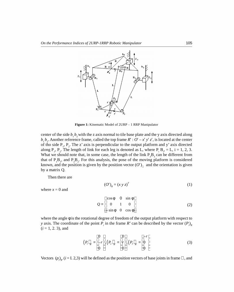
A kinematic model of the manipulator [19] is shown in Figure 1. Vertices of the outputplatform are denoted as platform joints P
i(i = 1, 2, 3), and vertices of the base platform are
denoted as bi, (i = 1, 2, 3). A fixed global reference system R : O – xyz is located at the
On the Performance Indices of 2URP-1RRP Robotic Manipulator 105
center of the side b1b
2with the z axis normal to tile base plate and the y axis directed along
b1b
2. Another reference frame, called the top frame R′ : O′ – x′ y′ z′, is located at the center
of tho side P1, P
2. The z’ axis is perpendicular to the output platform and y’ axis directed
along P1, P
2. The length of link for each leg is denoted as L, where P
iB
i, = L, i = 1, 2, 3.
What we should note that, in some case, the length of the link P3B
3can be different from
that of P1B
1, and P
2B
2. For this analysis, the pose of the moving platform is considered
known, and the position is given by the position vector (O′)ℜ and the orientation is givenby a matrix Q.
Then there are
(O′)R = (x y z)T (1)
where x = 0 and
cos sin
0 1 0
– sin 0 cosQ
φ 0 φ = φ φ
(2)
where the angle φ is the rotational degree of freedom of the output platform with respect toy axis. The coordinate of the point P
iin the frame R’ can be described by the vector (P
i)
R
(i = 1, 2. 3), and
( ) ( ) ( )1 2 3
0 0 –– , , 00 0 0
R R R
r
P r P r P′ ′ ′
= = =
(3)
Vectors (pi)
R′ (i = I. 2,3) will be defined as the position vectors of base joints in frame ℜ, and
Figure 1: Kinematic Model of 2URP – 1 RRP Manipulator
106 International Journal of Advanced Mechatronics and Robotics
( ) ( ) ( )1 2 3
1 2 3
0 0 –– , , 0
R R R
R
b R b R b
Z Z Z′ ′ ′
= = =
(4)
The vector (pi)ℜ (i = 1, 2, 3) in frame 0-xyz can be written as
(Pi)
R =Q (P
i)
R′ + (O′)R
(5)
Then the inverse kinematics of the parallel manipulator can be solved by writingfollowing constraint equation:
||[pi – b
i]
R|| = L (6)
(where i = 1,2,3)
Hence, for a given manipulator and for prescribed values of the position andorientation of the platform, the required actuator inputs can be directly computed from (6).that is
( )221 – –z L r y R z= ± + + + (7)
( )222 – – –z L r y R z= ± + + (8)
( )22 23 – – cos – sinz L r R y r z= ± φ + + φ + (9)
From (7)-(9), we can see that there are eight inverse kinematics solutions for a givenpose of the parallel manipulator. To obtain the inverse configuration as shown in Figure 1,each one of the signs “±” in (7)-(9) should be “+.”
3. JACOBIAN ANALYSIS OF PARALLEL MANIPULATORS
The Jacobian analysis of parallel manipulators is a much more difficult problem than thatof serial manipulators because there are many links that form a number of closed loops. Animportant limitation of parallel manipulator is that singular configurations may exist withinits work space where the manipulator gains one or more degrees of freedom and thereforeloses its stiffness completely. The Jacobian matrix is converted into two matrices: oneassociated with the direct kinematics and the other with the inverse kinematics. Dependingon which matrix is singular, a closed-loop mechanism may be at a direct kinematic singularconfiguration, an inverse kinematic singular configuration, or both.
A parallel manipulator is one which consists of a moving platform and a fixed baseconnected by several limbs. The moving platform serves as the end effector. Because of theclosed-loop construction, some of the joints can be controlled independently and the otherjoints are passive. Generally, the number of actuated joints should be equal to the numberof degrees of freedom of the manipulator.
On the Performance Indices of 2URP-1RRP Robotic Manipulator 107
Let the actuated joint variables be denoted by a vector q and the location of the movingplatform be described by a vector x. Then the kinematic constraints imposed by the limbscan be written in the general form [20].
F(x, q) = 0, (10)
Differentiating Eq. (1) with respect to time, the following relationship between theinput joint rates and end-effector output velocity can be written as
Jxx = J
qq (11)
Where
x
FJ
x
∂=∂ and q
FJ
q
∂=∂
The derivation above leads to two separate Jacobian matrices. Hence the overall Jacobianmatrix, J, can be written as
q= Jx (12)
Where J = Jq
-1 Jx. We note that the Jacobian matrix defined in Eq. (3) for a parallel manipulator
corresponds to the inverse Jacobian of a serial manipulator.
Jacobian matrix of 2URP and 1 RRP manipulator is obtained by differentiating Eq. (6).
J = j –1
qjx= B–1A (12a)
1
2
3
0 0
0 – 00 0 sin –
z z
A z z
r z z
− φ +
(12b)
( )
1
2
3 3
– – 0– – 0
sin – sin – cos
r y R z z
B r y R z z
y r z z Rr r z z
+ + + φ + φ + φ
(12c)
4. MEASURES OF KINEMATIC PERFORMANCE
4.1. Condition Number [4]
Let us consider the following linear system: Ax = b (13)
where A is an n x n matrix and x and b are n-dimensional vectors. The condition numberof the matrix A is a measure of its natural resistance to round-off error when the solutionof the linear system is computed. This resistance is expressed by the amplification factorby which a relative error ||δb||/||b|| in the data is multiplied to lead to a relative error

108 International Journal of Advanced Mechatronics and Robotics
||δx||/||x|| in the solution and it is called the condition number of the matrix. We can write thefollowing:
A(x+δx) = b + δb (14)or, by subtraction of eq. (14),
A(δx) = δb (15)
orδx = A–1 δb (16)
We now define the norm of a matrix as its amplifying power, i.e.,
||Ax|| ≤ || A||||x||, for all vectors x (17)
and equality holds for at least one non-zero vector. We can then write from eqs. (13 & 16),
||b|| ≤||A|| ||x|| (18)
and||δx||≤ ||A–1|| ||δb|| (19)
which leads to
|| || || ||
|| || || ||
x bk
x b
δ δ≤ (20)
where
k = ||A|| ||A–1|| (21)
is the condition number of A. which defines an upper bound for the amplification of therelative error. This definition of the condition number can be used with differentmatrix norms [19]. In this paper, the Euclidean – or Frobenius – norm was used. which isdefined as:
( )|| || TA tr AWA= (22a)
where W is the weight matrix
11W
n= (22b)
and A is assumed to be n x n.
or equivalently
21 1|| || | |i m j n
i j ijA a= == == Σ Σ (22c)
Other definitions for the norm could be adopted. For instance, the square root of thelargest Eigen value of ATA is often used. This definition has the advantage of being applicable
On the Performance Indices of 2URP-1RRP Robotic Manipulator 109
to non-square matrices. When this definition is adopted, the condition number of a matrixA becomes the square root of the ratio of the largest to the smallest Eigen value of thematrix ATA. The Euclidean norm was used here because it is frame-invariant and it is alsovery easy to compute.
The condition number of a Jacobian matrix of a manipulator [3] is
k ( j ) = k ( j –1) = ||J –1|| ||J|| (23)
4.2. Manipulability
The concept of manipulability of a manipulator was introduced by Yoshikawa [5]. Themanipulability is defined as the square root of the determinant of the product of themanipulator Jacobian by its transpose, i.e.,
( )det Tw JJ= (24)
The manipulability w is equal to the absolute value of the determinant of the Jacobianin case of a square
Jacobian. Using the singular value decomposition the manipulability can be written asfollows:
w = π (σi) (25)
where σiare the singular values of the Jacobian matrix J.
The manipulability index will have different values for the different used units. Therefore,it is convenient to use the manipulability index w using the normalized Jacobian J .
–1( ) ( )v qJ q T J q T= (26)
1 max 2 max max
1 1 1, ,...,v
m
T diagv v v
=
(27)
1 max 2 max max
1 1 1, ,...,q
n
T diagq q q
= (28)
where vjmax
is maximum angular or linear velocity for each element of the end-effectorvelocity v
j.
qi max
is maximum angular or linear velocity of joint i.
( )det ( ) ( )T
w J q J q= (29)
110 International Journal of Advanced Mechatronics and Robotics
For a square Jacobian matrix,
w = det TvdetJ(q) detT
q
–1 (30)
[∏m
i =1(q
i max/v
i max] (31)
4.3. Minimum Singular Value
The minimum singular value [6] changes more radically near singularities than the othersingular values. The minimum singular value forms the norm of the pseudo inverse part ofθ•and can be used to put an upper bound on required joint velocities.
||θ•|| ≤ (1/σ1) ||x || (32)
where θ•= J + x + (I – J + J) z (33)
σ1
is the minimum singular value and J+ is the pseudo inverse of J, z is an arbitrary vector.The first term of Eq. (D.21) represents the minimum norm solution to Eq. (D.20). Thesecond term, which can be used to optimize secondary criteria, will be called thehomogeneous solution.
5. RESULTS AND DISCUSSION
The condition number, manipulability and minimum singular value are analyzed for themanipulator and by using the MATLAB program, the results are obtained. The graphs areplotted showing the variation of each performance measure with reach. The plots are obtainedas mirror images about the vertical axis of the fixed platform.
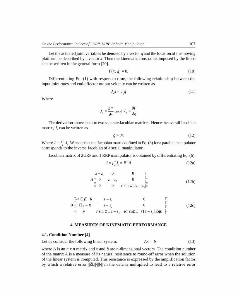
Figure 2: Manipulability Vs Reach for the Structure (r = 1, R = 2.5, L = 4) and Pose(Fi = 0, Z = ± 3.5 to ± 4.2)
On the Performance Indices of 2URP-1RRP Robotic Manipulator 111
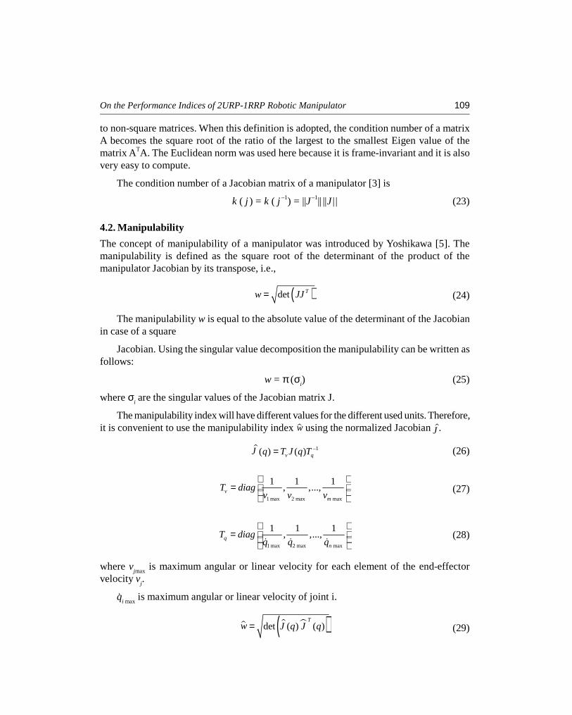
Figure 3: Manipulability Vs Reach for the Structure (r = 1, R = 3.5, L = 5) and Pose(Fi = 20, Z = ± 4.5 to ± 5.2)
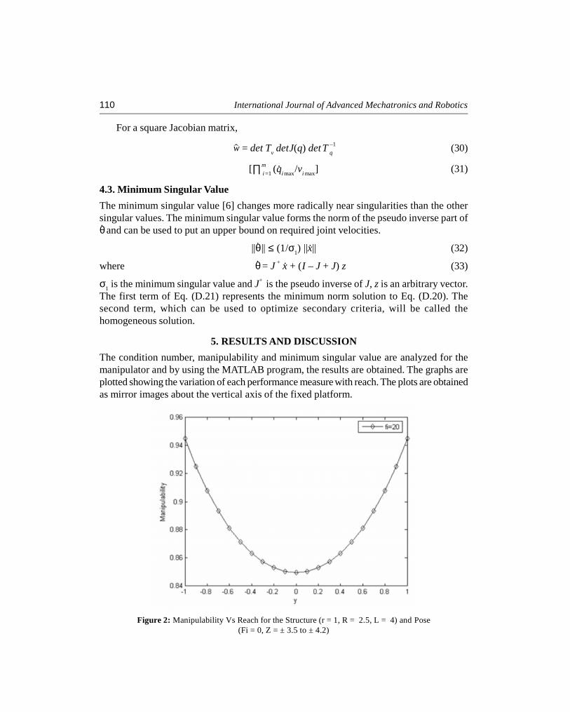
Figure 4: Minimum Singular Value Vs Reach for the Structure (r = 1, R = 3.5, L = 4) and Pose(Fi = 10, Z = ± 4.5 to ± 5.2)
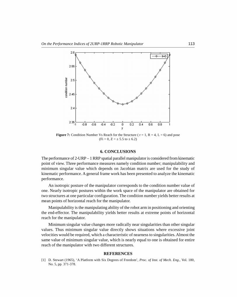
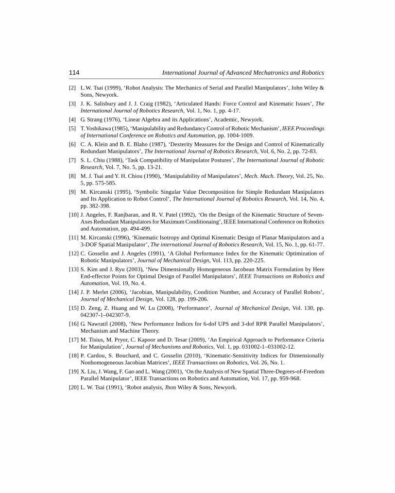
The isotropic posture for a given structure is the one having the condition number ofunity. Nearly isotropic postures that is a condition number value of 2.41 is obtained for twostructures of the manipulator and are shown in Figure 6 and Figure 7.
For easier manipulability that is for arbitrarily changing from one posture to another posturethe manipulability index should be equal to one. For two structures within the work spacemanipulability index values of 0.94 and 0.91 are obtained and shown in Figure 2 and Figure 3.
112 International Journal of Advanced Mechatronics and Robotics
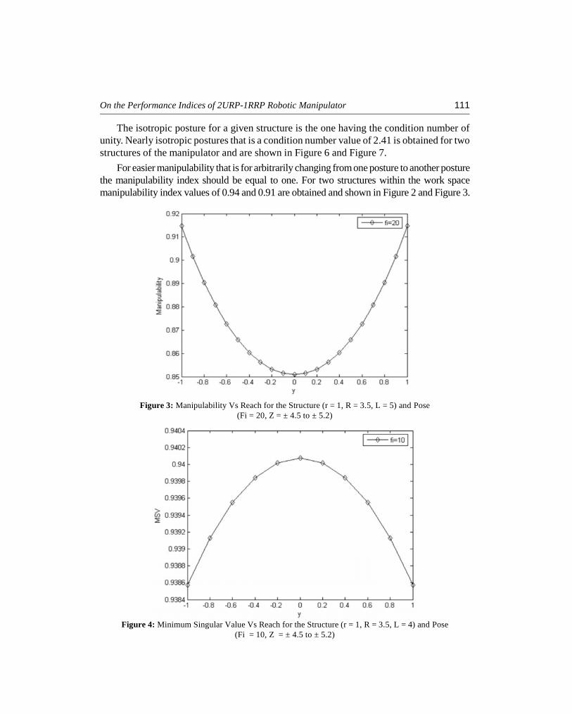
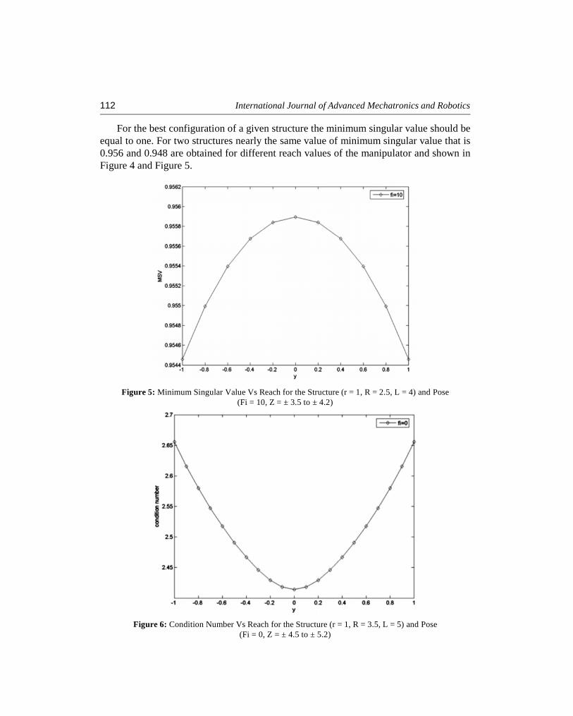
For the best configuration of a given structure the minimum singular value should beequal to one. For two structures nearly the same value of minimum singular value that is0.956 and 0.948 are obtained for different reach values of the manipulator and shown inFigure 4 and Figure 5.
Figure 5: Minimum Singular Value Vs Reach for the Structure (r = 1, R = 2.5, L = 4) and Pose(Fi = 10, Z = ± 3.5 to ± 4.2)
Figure 6: Condition Number Vs Reach for the Structure (r = 1, R = 3.5, L = 5) and Pose(Fi = 0, Z = ± 4.5 to ± 5.2)
On the Performance Indices of 2URP-1RRP Robotic Manipulator 113
6. CONCLUSIONS
The performance of 2-URP – 1 RRP spatial parallel manipulator is considered from kinematicpoint of view. Three performance measures namely condition number; manipulability andminimum singular value which depends on Jacobian matrix are used for the study ofkinematic performance. A general frame work has been presented to analyze the kinematicperformance.
An isotropic posture of the manipulator corresponds to the condition number value ofone. Nearly isotropic postures within the work space of the manipulator are obtained fortwo structures at one particular configuration. The condition number yields better results atmean points of horizontal reach for the manipulator.
Manipulability is the manipulating ability of the robot arm in positioning and orientingthe end-effector. The manipulability yields better results at extreme points of horizontalreach for the manipulator.
Minimum singular value changes more radically near singularities than other singularvalues. Thus minimum singular value directly shows situations where excessive jointvelocities would be required, which a characteristic of nearness to singularities. Almost thesame value of minimum singular value, which is nearly equal to one is obtained for entirereach of the manipulator with two different structures.
REFERENCES[1] D. Stewart (1965), ‘A Platform with Six Degrees of Freedom’, Proc. of Inst. of Mech. Eng., Vol. 180,
No. 5, pp. 371-378.
Figure 7: Condition Number Vs Reach for the Structure ( r = 1, R = 4, L = 6) and pose(Fi = 0, Z = ± 5.5 to ± 6.2)
114 International Journal of Advanced Mechatronics and Robotics
[2] L.W. Tsai (1999), ‘Robot Analysis: The Mechanics of Serial and Parallel Manipulators’, John Wiley &Sons, Newyork.
[3] J. K. Salisbury and J. J. Craig (1982), ‘Articulated Hands: Force Control and Kinematic Issues’, TheInternational Journal of Robotics Research, Vol. 1, No. 1, pp. 4-17.
[4] G. Strang (1976), ‘Linear Algebra and its Applications’, Academic, Newyork.[5] T. Yoshikawa (1985), ‘Manipulability and Redundancy Control of Robotic Mechanism’, IEEE Proceedings
of International Conference on Robotics and Automation, pp. 1004-1009.
[6] C. A. Klein and B. E. Blaho (1987), ‘Dexterity Measures for the Design and Control of KinematicallyRedundant Manipulators’, The International Journal of Robotics Research, Vol. 6, No. 2, pp. 72-83.
[7] S. L. Chiu (1988), ‘Task Compatibility of Manipulator Postures’, The International Journal of RoboticResearch, Vol. 7, No. 5, pp. 13-21.
[8] M. J. Tsai and Y. H. Chiou (1990), ‘Manipulability of Manipulators’, Mech. Mach. Theory, Vol. 25, No.5, pp. 575-585.
[9] M. Kircanski (1995), ‘Symbolic Singular Value Decomposition for Simple Redundant Manipulatorsand Its Application to Robot Control’, The International Journal of Robotics Research, Vol. 14, No. 4,pp. 382-398.
[10] J. Angeles, F. Ranjbaran, and R. V. Patel (1992), ‘On the Design of the Kinematic Structure of Seven-Axes Redundant Manipulators for Maximum Conditionaing’, IEEE International Conference on Roboticsand Automation, pp. 494-499.
[11] M. Kircanski (1996), ‘Kinematic Isotropy and Optimal Kinematic Design of Planar Manipulators and a3-DOF Spatial Manipulator’, The international Journal of Robotics Research, Vol. 15, No. 1, pp. 61-77.
[12] C. Gosselin and J. Angeles (1991), ‘A Global Performance Index for the Kinematic Optimization ofRobotic Manipulators’, Journal of Mechanical Design, Vol. 113, pp. 220-225.
[13] S. Kim and J. Ryu (2003), ‘New Dimensionally Homogeneous Jacobean Matrix Formulation by HereEnd-effector Points for Optimal Design of Parallel Manipulators’, IEEE Transactions on Robotics andAutomation, Vol. 19, No. 4.
[14] J. P. Merlet (2006), ‘Jacobian, Manipulability, Condition Number, and Accuracy of Parallel Robots’,Journal of Mechanical Design, Vol. 128, pp. 199-206.
[15] D. Zeng, Z. Huang and W. Lu (2008), ‘Performance’, Journal of Mechanical Design, Vol. 130, pp.042307-1–042307-9.
[16] G. Nawratil (2008), ‘New Performance Indices for 6-dof UPS and 3-dof RPR Parallel Manipulators’,Mechanism and Machine Theory.
[17] M. Tisius, M. Pryor, C. Kapoor and D. Tesar (2009), ‘An Empirical Approach to Performance Criteriafor Manipulation’, Journal of Mechanisms and Robotics, Vol. 1, pp. 031002-1–031002-12.
[18] P. Cardou, S. Bouchard, and C. Gosselin (2010), ‘Kinematic-Sensitivity Indices for DimensionallyNonhomogeneous Jacobian Matrices’, IEEE Transactions on Robotics, Vol. 26, No. 1.
[19] X. Liu, J. Wang, F. Gao and L. Wang (2001), ‘On the Analysis of New Spatial Three-Degrees-of-FreedomParallel Manipulator’, IEEE Transactions on Robotics and Automation, Vol. 17, pp. 959-968.
[20] L. W. Tsai (1991), ‘Robot analysis, Jhon Wiley & Sons, Newyork.