on the operational status of the iss plasma contactor ...€”2004-213184 1 on the operational...
TRANSCRIPT
Christian B. CarpenterQSS Group, Inc., Cleveland, Ohio
On the Operational Status of the ISS PlasmaContactor Hollow Cathodes
NASA/CR—2004-213184
August 2004
AIAA–2004–3425
https://ntrs.nasa.gov/search.jsp?R=20040110836 2018-06-02T17:09:38+00:00Z

The NASA STI Program Office . . . in Profile
Since its founding, NASA has been dedicated tothe advancement of aeronautics and spacescience. The NASA Scientific and TechnicalInformation (STI) Program Office plays a key partin helping NASA maintain this important role.
The NASA STI Program Office is operated byLangley Research Center, the Lead Center forNASA’s scientific and technical information. TheNASA STI Program Office provides access to theNASA STI Database, the largest collection ofaeronautical and space science STI in the world.The Program Office is also NASA’s institutionalmechanism for disseminating the results of itsresearch and development activities. These resultsare published by NASA in the NASA STI ReportSeries, which includes the following report types:
• TECHNICAL PUBLICATION. Reports ofcompleted research or a major significantphase of research that present the results ofNASA programs and include extensive dataor theoretical analysis. Includes compilationsof significant scientific and technical data andinformation deemed to be of continuingreference value. NASA’s counterpart of peer-reviewed formal professional papers buthas less stringent limitations on manuscriptlength and extent of graphic presentations.
• TECHNICAL MEMORANDUM. Scientificand technical findings that are preliminary orof specialized interest, e.g., quick releasereports, working papers, and bibliographiesthat contain minimal annotation. Does notcontain extensive analysis.
• CONTRACTOR REPORT. Scientific andtechnical findings by NASA-sponsoredcontractors and grantees.
• CONFERENCE PUBLICATION. Collectedpapers from scientific and technicalconferences, symposia, seminars, or othermeetings sponsored or cosponsored byNASA.
• SPECIAL PUBLICATION. Scientific,technical, or historical information fromNASA programs, projects, and missions,often concerned with subjects havingsubstantial public interest.
• TECHNICAL TRANSLATION. English-language translations of foreign scientificand technical material pertinent to NASA’smission.
Specialized services that complement the STIProgram Office’s diverse offerings includecreating custom thesauri, building customizeddatabases, organizing and publishing researchresults . . . even providing videos.
For more information about the NASA STIProgram Office, see the following:
• Access the NASA STI Program Home Pageat http://www.sti.nasa.gov
• E-mail your question via the Internet [email protected]
• Fax your question to the NASA AccessHelp Desk at 301–621–0134
• Telephone the NASA Access Help Desk at301–621–0390
• Write to: NASA Access Help Desk NASA Center for AeroSpace Information 7121 Standard Drive Hanover, MD 21076

Christian B. CarpenterQSS Group, Inc., Cleveland, Ohio
On the Operational Status of the ISS PlasmaContactor Hollow Cathodes
NASA/CR—2004-213184
August 2004
National Aeronautics andSpace Administration
Glenn Research Center
Prepared under Contract NAS3–00145
Prepared for the40th Joint Propulsion Conference and Exhibitcosponsored by the AIAA, ASME, SAE, and ASEEFort Lauderdale, Florida, July 11–14, 2004
AIAA–2004–3425

Available from
NASA Center for Aerospace Information7121 Standard DriveHanover, MD 21076
National Technical Information Service5285 Port Royal RoadSpringfield, VA 22100
Available electronically at http://gltrs.grc.nasa.gov

NASA/CR—2004-213184 1
On the Operational Status of the ISS Plasma Contactor Hollow Cathodes
Christian B. Carpenter QSS Group, Inc.
Cleveland, Ohio 44135
The Plasma Contactor Unit (PCU) was developed by the Rocketdyne division of The Boeing Company to control charging of the International Space Station (ISS). Each PCU contains a Hollow Cathode Assembly (HCA), which emits the charge control electrons. The HCAs were designed and fabricated at NASA’s Glenn Research Center (GRC). GRC’s HCA development program included manufacture of engineering, qualification, and flight model HCAs as well as qualification and wear tests. GRC tracks the on-orbit data for the flight HCAs in order to ascertain their overall health. As of April 5, 2004, 43 ignitions and over 6000 hours have been accumulated on a single unit. The flight HCAs continue to operate flawlessly. This paper will discuss the operation of the HCAs during ground tests and on-orbit operation from initial startup to April 30, 2004.
I. Introduction he International Space Station (ISS) high voltage solar arrays deliver output voltages of 140 to 160 V. The electrical configuration of the ISS and the plasma current balance could cause the station to float at voltages
predicted to be as much as 120 V below the ambient space plasma if no charge control device is used. If large negative floating potentials are present, the ISS could interact with ambient space plasma. These interactions could include arcing and sputter erosion.
The development of a plasma contactor for charge control aboard a space station began in 1992 with the United States’ Space Station Freedom plasma contactor project at NASA’s Glenn Research Center (GRC). The information and research from this program was carried over into the design of the International Space Station (ISS) plasma contactors in 1994. Hollow cathodes were chosen for this application due to their efficient, variable, and rapid emission of high electron currents.1
The plasma contactor units (PCUs), developed by the Rocketdyne division of The Boeing Company, and shown in Fig. 1, use a hollow cathode assembly (HCA), shown in Fig. 2, to generate electrons used for ISS charge control. GRC was tasked with the development and delivery of the flight HCAs. The mechanical design of the HCA is described in Ref. 2. GRC’s HCA development program included manufacture of engineering, qualification, and flight model HCAs as well as qualification and wear tests. During the development program, two main long duration cathode tests were conducted. During one of these tests, a single cathode reached 28,000 hours of operation before an ignition failure.3 In the second test, four units were operated simultaneously with one cathode reaching 19,000 hours without failure before the test was voluntarily shut down for cathode analysis.4,5 Table I lists the final status of each of these life test HCAs. The ignition reliability of the HCAs was also tested. In one test, an HCA reached over 32,000 ignitions without failure.6
The first two plasma contactor units (PCUs), which were acceptance tested at GRC, were delivered aboard the shuttle Discovery in October of 2000 by the crew of STS-92. Two PCUs are used to ensure full redundancy, and they are co-located on the Z1 truss, shown in Fig. 3, of the ISS in the area marked on Fig. 4. The first ignition of a PCU aboard the ISS occurred on October 16, 2000.
T

NASA/CR—2004-213184 2
II. Operational Requirements The single primary design requirement for the PCUs was to control the ISS structure floating potential at all
points on the station to ±40 V of the local space plasma potential. The effect of v x B charging as the ISS moves through the Earth’s magnetic tightens this requirement to ±20 V.1,6 The PCU carries enough xenon to operate continuously for 18,000 hours, enabling it to perform this function for more than two years.
Numerous requirements were instituted for the design of the HCAs. One requirement of the HCAs is to emit current up to 10 A in a self-regulating manner under dynamic conditions at clamping voltages ≤20 V between HCA common and the local space plasma potential. Another requirement is that the HCA be capable of operating for a minimum of 18,000 hours, which is based on the expellant available in the PCU. Ignition requirements were also instituted including the requirement that the HCA be capable of 6,000 ignitions with no less than 99% reliability.2
III. On-Orbit Operation Status The first two flight HCAs (identified as HCA.001-F in PCU1 and HCA.003-F in PCU2) are currently still in
operation aboard the space station. Though originally designed for continuous operation, the HCAs presently operate only during extra-vehicular activities (EVAs), shuttle docking, or as deemed necessary. The operation of the HCAs was changed in order to extend the life of the PCU by operating the HCA for vehicle potential control during mission critical events, which necessitate single-fault tolerant capability. The HCAs are normally operated simultaneously for the purpose of redundancy. The HCAs maintain a continuous flow of approximately 6 sccm of xenon gas for the duration of their operation. The HCAs operate by emitting three amperes of current to the anode and are allowed to emit current as necessary to the space plasma. The current that is emitted to the space plasma is termed “clamping current”. Table II shows the status of each flight cathode as of April 5, 2004. As of that date, HCA.001-F had accumulated 4,047 hours of on-orbit operation, with 40 ignitions and HCA.003-F had accumulated 6,031 hours with 43 ignitions.
IV. Analysis of On-Orbit Operation Parameters such as ignition time and anode voltage serve as a good measure of cathode health. As cathodes
begin to degrade with operation time, ignition times and anode voltages have been seen to increase in ground based development testing. Barium depletion, and contamination, as well as other factors, can all cause increases in ignition time. Several long duration wear tests have shown that anode voltages begin to increase with increasing operation time, usually after 500 to 1000 hours of operation.3,7,8 Several mechanisms have been speculated as the cause of these changes such as: geometric changes in the cathode due to deposition, erosion, or sputtering, pressure changes, and thermochemistry.8,9 No significant geometric changes are expected to occur on the flight HCAs as ground based wear testing has shown that even after thousands of hours of operation there are no geometric changes of the cathode orifices.3,4,10
Ground-based performance testing was conducted on each of the flight HCAs prior to installation in their respective PCUs. Two modes of operation were investigated. Diode mode operation consisted of operation with electron current to the anode only. Diode mode operation was characterized over a range of anode currents from 2.75 to 3 A and a range of xenon flow rates from 4.5 to 9 sccm. Triode mode operation consisted of operation with 3 A of electron current to the anode and a clamping current emitted to the vacuum facility walls. Triode mode operation was characterized over a clamping current range of 0.5 to 10 A and a xenon flow rate range of 6 to 8.5 sccm.
Ignition times versus ignition number for all ignitions accumulated by the flight HCAs during ground-based performance testing and on-orbit operation are shown in Fig. 5. For this study, the ignition time is defined to be the duration from the start of the cathode warm-up procedure to the measurement of a voltage that indicates plasma has formed between the cathode and anode electrode. The first ignition time seen in the ground based test data is lengthy though consistent with starting a new cathode. The data show that the on-orbit ignition times tend to oscillate, but remain below six minutes and are in the range of the ground-based data. Table III shows the maximum and average on-orbit ignition times for the flight HCAs. On-orbit ignition times range from the minimum 210 seconds to a maximum of 353 seconds. There is no apparent pattern in the on-orbit ignition times and they do not show any trends of increasing duration with time.
An operating segment is defined as the period from the ignition of an HCA until the HCA is commanded off and reaches zero emission current. Operating segments are numbered by their respective ignition. The first operating segment of HCA.001-F was October 20, 2000. HCA.001-F was the only HCA that operated during this period and accumulated 1.2 hours of operation. Figure 6 plots the clamping current during this operating segment. The clamping current was measured to be 9 mA average and 20 mA peak. During ground testing, HCA.001-F anode voltages ranged from 10.3 to 13.5 V for the 6 sccm triode mode test. For a xenon flow rate of 6 sccm, the diode

NASA/CR—2004-213184 3
mode test of HCA.001-F measured an anode voltage range of 12.9 to 13.5 V. Figure 7 shows the measured values of anode voltage for on-orbit operation Segment 1. The anode voltages averaged 14.5 V and peaked at 15.0 V for Segment 1. The deviation in anode voltages from the ground-based testing and the on-orbit operation can be attributed to the atmospheric exposure encountered from the time of the tests until the on-orbit operation, the short operation time of the HCA during this operating segment, or small differences in flow rates between on-orbit and ground based testing. In addition, this amount of deviation is routinely seen in laboratory testing on day-to-day tests on single HCAs.
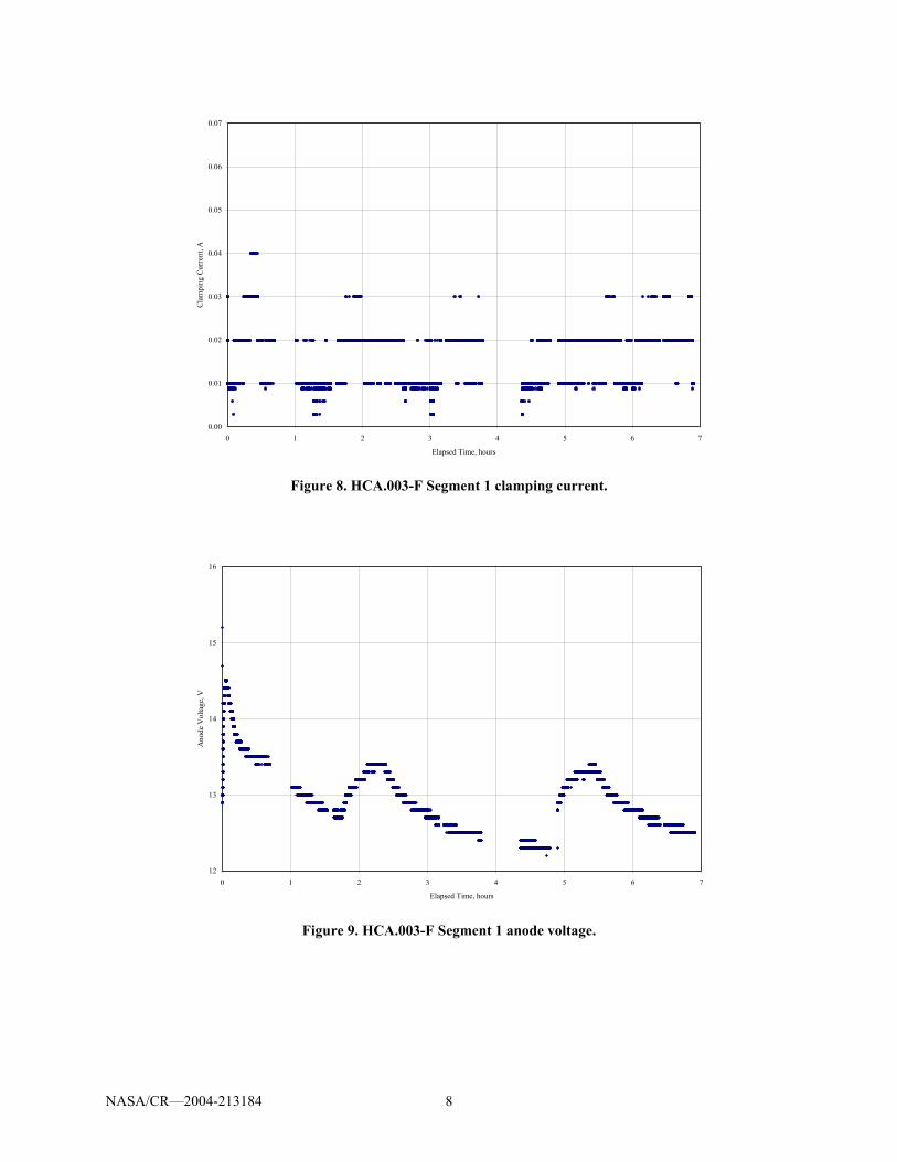
The first operating segment of HCA.003-F was November 17, 2000. HCA.003-F accumulated almost seven hours of operation during this segment. HCA.001-F was operated during the final hour of this segment; this was operation Segment 2 for HCA.001-F. Clamping currents for HCA.003-F are shown in Fig. 8. The average claming current for this segment was 21 mA with a peak current of 47 mA. The behavior of the clamping current for this operation segment compares well to that of HCA.001-F Segment 1. The anode voltages for HCA.003-F during Segment 1 are shown in Fig. 9. The average anode voltage was 13.0 V and the peak value was 16.2 V. The ground-based performance tests of HCA.003-F measured an anode voltage range of 10.3 to 13.8 V for triode mode operation. Anode voltages of 13.7 to 14.9 V were measured for 6 sccm diode mode operation. The average anode voltage for on-orbit operation of HCA.003-F compares well with its ground-based data and with the data from HCA.001-F in both on-orbit operation and ground-based testing. Simultaneous on-orbit operation did not appear to effect the operation of either HCA.
As of this study, the last time the HCAs were operated simultaneously was from March 27, 2004 to April 5, 2004. Table IV shows the total operation time, ignition number and ignition duration for these operation segments. Figure 10 and Fig. 11 plot the clamping current versus operation time for their respective operation segments. The average current for HCA.001-F was 15 mA and the average for HCA.003-F was 17 mA. The maximum current for both cathodes was 53 mA. This data is similar in both form and magnitude to the initial operation of both HCAs. Figure 12 and Fig. 13 plot the anode voltages versus time for these segments. The average anode voltage for HCA.001-F was 13.5 V and the average for HCA.003-F was 12.9 V. The maximum anode voltage for HCA.001-F was 14.8 V and the maximum for HCA.003-F was 14.0 V. The performance of HCAs does not appear to change in single or tandem operation. The average voltages seen during these segments are similar to that seen in ground-based testing. This shows that the performance of the HCAs has remained generally unchanged since their ground-based testing and first on-orbit operation.
V. Conclusion Anode voltage, ignition time, and clamping current values for the ISS PCU HCAs are being tracked to evaluate
the health of the HCAs. The HCAs continue to produce the current required for charge control with out incident. Anode voltage and ignition times are being compared with design specifications, historical knowledge, and ground-based testing to qualify cathode health. Ignition times and anode voltages for the most recent operating segment compare well with ground-based test data and initial on-orbit operation data. Steady state anode voltages remain well below the maximum value of 20 V and there is no indication that this voltage is increasing with operating time. Ignition times remain low and there is no indication of increasing ignition time. Both anode voltage and ignition time parameters indicate that the HCAs are in good health and should continue to provide reliable clamping currents as designed.
References
1 Patterson, M.J., et al., “Plasma Contactor for Space Station Freedom,” AIAA Paper No. 93–2228, June 1993. 2 Patterson, M.J., et al., “Space Station Cathode Design, Performance, and Operating Specifications,” IEPC Paper No. 97–
170, August 1997. Also: NASA/TM—1998-206529, May 1998. 3 Verhey, T.R., “28,000 Hour Xenon Hollow Cathode Life Test Results,” IEPC Paper No. 97–168, August 1997. 4 Soulas, G.C., “Multiple Hollow Cathode Wear Testing for the Space Station,” AIAA Paper No. 94–3310, June 1994. 5 Carpenter, C.B., “Comparison of On-Orbit and Ground Based Hollow Cathode Operation,” AIAA Paper No. 2002–4098,
July 2002. 6 Zakany, J. and Pinero, L., “Space Station Cathode Ignition Test Status at 32,000 Cycles,” IEPC Paper No. 97–167, August
1997. 7 Brophy, J. and Garner, C, “A 5,000 Hour Xenon Hollow Cathode Life Test,” AIAA Paper No. 91–2122, June 1991. 8 Verhey, T.R. and MacRae, G.S., “Requirements for Long-Life Operation of Inert Gas Hollow Cathode – Preliminary
Results,” AIAA Paper No. 90–2586, July 1990.

NASA/CR—2004-213184 4
9 Kovaleski, S.D., “Life Model of Hollow Cathodes Using a Barium Calcium Aluminate Impregnated Tungsten Emitter,”
IEPC Paper No. 01–276, October 2001. 10 Carpenter, C.B., “Comparison of On-Orbit and Ground Based Hollow Cathode Operation,” AIAA Paper No. 2003–5145,
July 2003.
Table I. Final status of life test cathodes.
Unit Accumulated Hours Accumulated Ignitions HCA-003 12,415 38 HCA-006 8,030 Data not Available HCA-010 15,876 4,424 HCA-013 18,873 59
Table II. Status of flight cathodes as of April 5, 2004.
Unit Accumulated Operation Time, hrs Accumulated Ignitions/Operating Segments HCA.001-F 4,047 40 HCA.003-F 6,031 43
Table III. Maximum and average on-orbit ignition times.
Unit Maximum Ignition Time, sec Average Ignition Time, sec HCA.001-F 335 255 HCA.003-F 353 252
Table IV. Operation from March 27, 2004 to April 5, 2004.
Unit Accumulated Operation Time, hrs
Ignition/Operating Segment Number Ignition Time, sec
HCA.001-F 226 40 290 HCA.003-F 232 43 220

NASA/CR—2004-213184 5
Figure 1. Plasma contactor unit.
Figure 2. Plasma contactor flight hollow cathode assemblies.

NASA/CR—2004-213184 6
PCUs
Figure 3. Location of plasma contactors on the Z1 truss.
PCUs
Figure 4. Location of plasma contactors on the ISS.
HCA Ignition Time vs. Ignition Number
210
260
310
360
410
460
510
560
610
660
1 6 11 16 21 26 31 36 41 46
Ignition Number
Igni
tion
Tim
e, se
c
HCA.001-F Ground HCA.003-F Ground
HCA.001-F Space HCA.003-F Space
Figure 5. HCA ignition time versus ignition number.

NASA/CR—2004-213184 7
0.00
0.01
0.02
0.03
0.04
0.05
0.06
0.07
0 0.2 0.4 0.6 0.8 1 1.2 1.4
Elasped Time, hours
Cla
mpi
ng C
urre
nt, A
Figure 6. HCA.001-F Segment 1 clamping current.
12
13
14
15
16
0 0.2 0.4 0.6 0.8 1 1.2 1.4
Elasped Time, hours
Ano
de V
olta
ge, V
Figure 7. HCA.001-F Segment 1 anode voltage.
NASA/CR—2004-213184 8
0.00
0.01
0.02
0.03
0.04
0.05
0.06
0.07
0 1 2 3 4 5 6 7
Elapsed Time, hours
Cla
mpi
ng C
urre
nt, A
Figure 8. HCA.003-F Segment 1 clamping current.
12
13
14
15
16
0 1 2 3 4 5 6 7
Elapsed Time, hours
Ano
de V
olta
ge, V
Figure 9. HCA.003-F Segment 1 anode voltage.

NASA/CR—2004-213184 9
0.00
0.01
0.02
0.03
0.04
0.05
0.06
0.07
0 50 100 150 200 250
Elapsed Time, hours
Cla
mpi
ng C
urre
nt, A
Figure 10. HCA.001-F Segment 40 clamping current.
0.00
0.01
0.02
0.03
0.04
0.05
0.06
0.07
0 50 100 150 200 250
Elapsed Time, hours
Cla
mpi
ng C
urre
nt, A
Figure 11. HCA.003-F Segment 43 clamping current.

NASA/CR—2004-213184 10
12
13
14
15
16
0 50 100 150 200 250
Elapsed Time, hours
Ano
de V
olta
ge, V
Figure 12. HCA.001-F Segment 40 anode voltage.
12
13
14
15
16
0 50 100 150 200 250
Elapsed Time, hours
Ano
de V
olta
ge, V
Figure 13. HCA.003-F Segment 43 anode voltage.


This publication is available from the NASA Center for AeroSpace Information, 301–621–0390.
REPORT DOCUMENTATION PAGE
2. REPORT DATE
19. SECURITY CLASSIFICATION OF ABSTRACT
18. SECURITY CLASSIFICATION OF THIS PAGE
Public reporting burden for this collection of information is estimated to average 1 hour per response, including the time for reviewing instructions, searching existing data sources,gathering and maintaining the data needed, and completing and reviewing the collection of information. Send comments regarding this burden estimate or any other aspect of thiscollection of information, including suggestions for reducing this burden, to Washington Headquarters Services, Directorate for Information Operations and Reports, 1215 JeffersonDavis Highway, Suite 1204, Arlington, VA 22202-4302, and to the Office of Management and Budget, Paperwork Reduction Project (0704-0188), Washington, DC 20503.
NSN 7540-01-280-5500 Standard Form 298 (Rev. 2-89)Prescribed by ANSI Std. Z39-18298-102
Form Approved
OMB No. 0704-0188
12b. DISTRIBUTION CODE
8. PERFORMING ORGANIZATION REPORT NUMBER
5. FUNDING NUMBERS
3. REPORT TYPE AND DATES COVERED
4. TITLE AND SUBTITLE
6. AUTHOR(S)
7. PERFORMING ORGANIZATION NAME(S) AND ADDRESS(ES)
11. SUPPLEMENTARY NOTES
12a. DISTRIBUTION/AVAILABILITY STATEMENT
13. ABSTRACT (Maximum 200 words)
14. SUBJECT TERMS
17. SECURITY CLASSIFICATION OF REPORT
16. PRICE CODE
15. NUMBER OF PAGES
20. LIMITATION OF ABSTRACT
Unclassified Unclassified
Final Contractor Report
Unclassified
1. AGENCY USE ONLY (Leave blank)
10. SPONSORING/MONITORING AGENCY REPORT NUMBER
9. SPONSORING/MONITORING AGENCY NAME(S) AND ADDRESS(ES)
National Aeronautics and Space AdministrationWashington, DC 20546–0001
Available electronically at http://gltrs.grc.nasa.gov
August 2004
NASA CR—2004-213184AIAA–2004–3425
E–14680
WBS–22–982–10–02NAS3–00145
16
On the Operational Status of the ISS Plasma Contactor Hollow Cathodes
Christian B. Carpenter
Hollow cathodes; Ion engines
Unclassified -UnlimitedSubject Category: 20 Distribution: Nonstandard
QSS Group, Inc.21000 Brookpark RoadCleveland, Ohio 44135
Prepared for the 40th Joint Propulsion Conference and Exhibit cosponsored by AIAA, ASME, SAE, and ASEE, FortLauderdale, Florida, July 11–14, 2004. Project Manager, Thomas P. Burke, Systems Engineering Division, organizationcode 7800, 216–433–5172.
The Plasma Contactor Unit (PCU) was developed by the Rocketdyne division of The Boeing Company to control chargingof the International Space Station (ISS). Each PCU contains a Hollow Cathode Assembly (HCA), which emits the chargecontrol electrons. The HCAs were designed and fabricated at NASA’s Glenn Research Center (GRC). GRC’s HCAdevelopment program included manufacture of engineering, qualification, and flight model HCAs as well as qualificationand wear tests. GRC tracks the on-orbit data for the flight HCAs in order to ascertain their overall health. As ofApril 5, 2004, 43 ignitions and over 6000 hours have been accumulated on a single unit. The flight HCAs continueto operate flawlessly. This paper will discuss the operation of the HCAs during ground tests and on-orbit operationfrom initial startup to April 30, 2004.

