on the limits of leakage power reduction in caches
DESCRIPTION
On the Limits of Leakage Power Reduction in Caches. Yan Meng, Tim Sherwood and Ryan Kastner UC, Santa Barbara HPCA-2005. Overview. Caches are good targets for tackling the leakage problem Much work has been done in this field Gated -Vdd - PowerPoint PPT PresentationTRANSCRIPT

On the Limits of Leakage Power Reduction in Caches
Yan Meng, Tim Sherwood and Ryan Kastner
UC, Santa Barbara
HPCA-2005
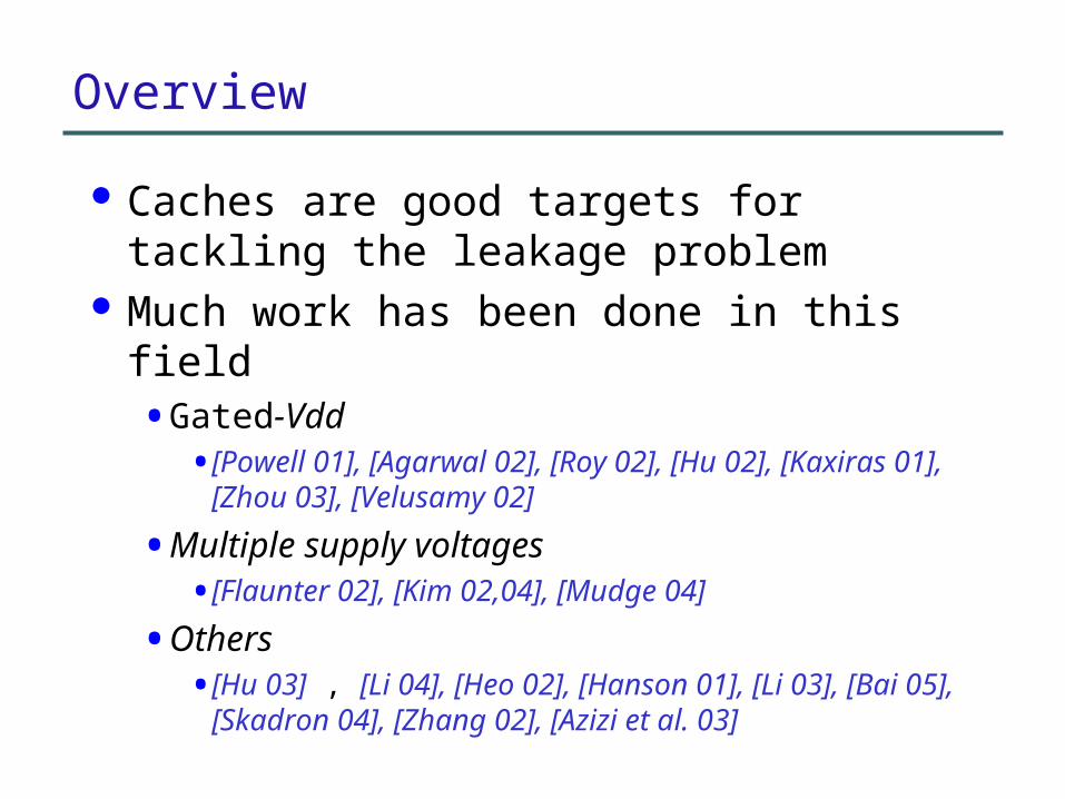
Overview
Caches are good targets for tackling the leakage problem
Much work has been done in this field • Gated-Vdd
• [Powell 01], [Agarwal 02], [Roy 02], [Hu 02], [Kaxiras 01], [Zhou 03], [Velusamy 02]
• Multiple supply voltages• [Flaunter 02], [Kim 02,04], [Mudge 04]
• Others• [Hu 03] , [Li 04], [Heo 02], [Hanson 01], [Li 03], [Bai
05], [Skadron 04], [Zhang 02], [Azizi et al. 03]
Research Question and Finding
What is the best leakage power saving we could hope to achieve with existing techniques?
Far more potential left for further reducing leakage power in caches

Outline
Motivation Definitions Optimal approach The generalized model Experimental results Conclusions

Motivation
Why to study leakage problem?• Leakage power: dominant source for power consumption as
technology scales down below 100nm
0%
20%
40%
60%
80%
100%
1999 2001 2003 2005 2007 2009
Year
Lea
kage
Pow
er/T
otal
Pow
er
Fig: Projected leakage power consumption as a fraction of the total power consumption according to International Technology Roadmap for Semiconductor

Motivation
Why to tackle the leakage problem through caches?
• Caches : huge chip area (50% 2005 [ITRS])
• Major source for leakage power consumption
Alpha 21364 microprocessor die photo[http://www.oracle.com/technology/products/rdb/pdf/2002_tech_forums/rdbtf_2002_opt_on_alpha_mdr.pdf]

Motivation
How to tackle the problem with existing techniques?• Keep frequently accessed cache lines active to ensure
high performance
• Turn off cache lines that are not used for a long time
• Use low supply voltage to save power for the rest
What’s the best that the existing circuit and architecture techniques could achieve? How much room is left for further research?

Definitions – Cache Interval
Time between two successive accesses to the same cache line
access(i) access(i+1)
Time
|Ii|

Definitions --- Operating Modes
Active mode• Power on the whole cache line
• No power saving
Active
Voltage
|Ii|
Vdd
0 Sleep mode [Roy01, Hu01]
• Sleep/“turn off” transistors
• Lose data
• Refetch data with high overhead
Drowsy mode [Flautner02,Mudge04]
• Use low supply voltage to save power when it is not needed
• Preserve data for fast reaccess
• Wake up to the high voltage and return data
s1 s2Sleep
Voltage
|Ii|
Vdd
s30
s4
*
d1 d3Drowsyd2
Voltage
|Ii|
Vdd
Vddlow
0

Choosing Operating Modes
Active mode Sleep mode Drowsy mode
|Ii|
?

Optimal Approach
Differences • Studying optimality
• Combining all three modes to achieve the maximal leakage power saving
Optimal policy• Oracle knowledge of future address trace
• Applying the appropriate operating mode on each cache interval
• Obtaining optimal leakage power saving
• Formal proof of the optimality

Which mode to apply on each interval? Active-drowsy inflection point a
• The least amount of time drowsy mode needs to save energy
Sleep-drowsy inflection point b• The time where sleep and drowsy modes
consume the same amount of energy
Inflection Points

Selecting Operating Modes with Inflection Points
ActiveInterval
Drowsy Interval
Sleep Interval
ActiveMode
Drowsy Mode
Sleep Mode
I
0<|I|≤a
|I|>b
a<|I|≤b
Optimality
|I|?

Active-drowsy inflection point a
Calculating Inflection Points
31}0)({minarg ddtEa savingDrowsyt
Di
iiLSleep
iiiLDrowsy
SleepDrowsy
CssPE
ddPE
tEtEtb
4,3,2,1
3,2,1
*)(
*)(
)}()(:{
s1 s2Sleep
Voltage
|Ii|
Vdd
s30
s4
*d1 d3
Drowsyd2
Voltage
|Ii|
Vdd
Vddlow
0
d1 d3
Voltage
|Ii|
Vdd
Vddlow
0
Drowsy
Sleep-drowsy inflection point b
CD

Deriving the interval lengths with perfect knowledge of the future address trace
Fetching any needed data just before it is needed
Avoiding any performance impact Taking into account the power cost of
just-in-time refetch CD
Saving Leakage Power without Performance Degradation

(e) The drowsy mode w/ perfect prefetching
(d) The drowsy mode w/o perfect prefetching
Saving Leakage Power without Performance Degradation
access(i) access(i+1) Transition energy
Fetch energyEnergy consumption due to system stall(a) The active mode
Active energy
Drowsy energy
Saved energy
(b) The sleep mode w/o perfect prefetching
(c) The sleep mode w/ perfect prefetching
Just before needed Just before needed

The Generalized Model
Parameterized model
• Inputs• Wake-up latencies
• Interval distribution
• Leakage power of each state
• Transition energy between states
• Outputs• Optimal savings of OPT-Drowsy,
OPT-Sleep, and OPT-Hybrid
• Can be extended to accommodate future technologies and power saving modes
Publicly available• http://express.ece.ucsb.edu/software/leakage.html
Active
SleepDrowsyP(Drowsy)
EAD
ESAEDA
EAS
P(Active)
P(Sleep)

Methodology
Core: Compaq Alpha 21264 [Kessler 99]• Memory
• 2-way L1 instruction and data caches, 64KB
• Unified direct mapped L2 cache, 2MB
• LRU replacement policy Tools
• SimAlpha simulator
• HotLeakage• Leakage power and dynamic cost
• Parameters: taken from HotLeakage
Averaged results over all benchmark applications

Calculating Inflection Points
• The sleep-drowsy point decreases from 180nm to 70nm• Because the leakage power consumption increases while the
dynamic power consumption caused by an induced miss decreases
• Our approach can be parameterized and applied to many other memory technologies
• 70nm, the most advanced technology, is used in the rest of our study
Inflection points(Cycles) 180nm 130nm 90nm 70nmActive-drowsy point 6 6 6 6Sleep-drowsy point 103084 10328 5088 1057
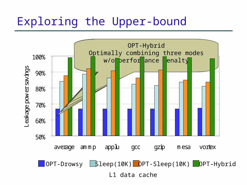
Exploring the Upper-bound
50%
60%
70%
80%
90%
100%
average ammp applu gcc gzip mesa vortex
Lea
kage
pow
er s
avin
gs
OPT-Drowsy Sleep(10K) OPT-Sleep(10K) OPT-Hybrid
OPT-DrowsyNo performance penalty for waking up data
Sleep(10K)Turning off cache lines after 10K cycles
[Hu01]
OPT-Sleep(10K)Turning off cache lines with lengths greater
than 10K cycles
OPT-HybridOptimally combining three modes w/o
performance penalty
L1 data cache

Research Finding
Larger leakage saving can be achieved for data cache Drowsy and sleep modes each achieve fairly high savings Savings are complementary: potential in combining drowsy and
sleep technologies
50%
60%
70%
80%
90%
100%
Instruction cache Data cache
Le
aka
ge
po
we
r sa
vin
gs
OPT-Drowsy Sleep(10K) OPT-Sleep(10K) OPT-Hybrid
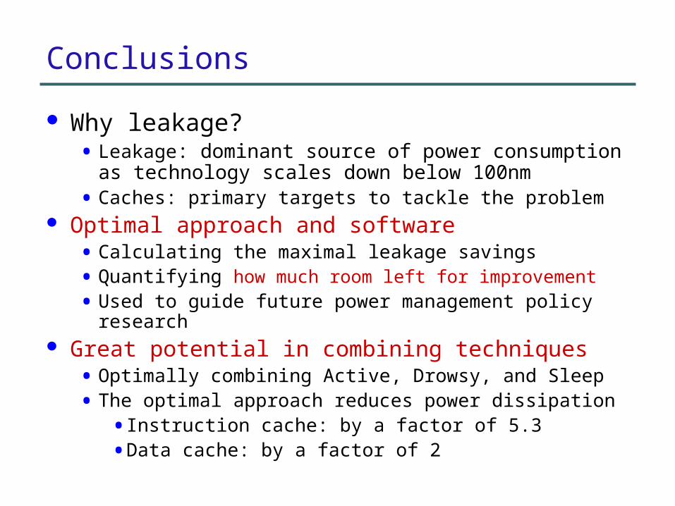
Conclusions
Why leakage?• Leakage: dominant source of power consumption as
technology scales down below 100nm
• Caches: primary targets to tackle the problem Optimal approach and software
• Calculating the maximal leakage savings
• Quantifying how much room left for improvement
• Used to guide future power management policy research Great potential in combining techniques
• Optimally combining Active, Drowsy, and Sleep
• The optimal approach reduces power dissipation
• Instruction cache: by a factor of 5.3
• Data cache: by a factor of 2