on the development of a nonlinear time-domain numerical
TRANSCRIPT

On the development of a nonlinear time-domain numerical method fordescribing vortex-induced vibration and wake interference of twocylinders using experimental resultsArmin, M., Day, S., Karimirad, M., & Khorasanchi, M. (2021). On the development of a nonlinear time-domainnumerical method for describing vortex-induced vibration and wake interference of two cylinders usingexperimental results. Nonlinear Dynamics. https://doi.org/10.1007/s11071-021-06527-8
Published in:Nonlinear Dynamics
Document Version:Publisher's PDF, also known as Version of record
Queen's University Belfast - Research Portal:Link to publication record in Queen's University Belfast Research Portal
Publisher rightsThis article is licensed under a Creative Commons Attribution 4.0 International License, which permits use,sharing, adaptation, distribution and reproduction in any mediumor format, as long as you give appropriate credit to the originalauthor(s) and the source, provide a link to the Creative Commons licence, and indicate if changes were made. The images orother third party material in this article are included in the article’sCreative Commons licence, unless indicated otherwise in a creditline to the material. If material is not included in the article’s Creative Commons licence and your intended use is not permitted bystatutory regulation or exceeds the permitted use, you will needto obtain permission directly from the copyright holder. To viewa copy of this licence, visit http://creativecommons.org/licenses/by/4.0/.General rightsCopyright for the publications made accessible via the Queen's University Belfast Research Portal is retained by the author(s) and / or othercopyright owners and it is a condition of accessing these publications that users recognise and abide by the legal requirements associatedwith these rights.
Take down policyThe Research Portal is Queen's institutional repository that provides access to Queen's research output. Every effort has been made toensure that content in the Research Portal does not infringe any person's rights, or applicable UK laws. If you discover content in theResearch Portal that you believe breaches copyright or violates any law, please contact [email protected].
Download date:25. Jan. 2022

Nonlinear Dynhttps://doi.org/10.1007/s11071-021-06527-8
ORIGINAL PAPER
On the development of a nonlinear time-domain numericalmethod for describing vortex-induced vibration and wakeinterference of two cylinders using experimental results
Milad Armin · Sandy Day ·Madjid Karimirad · Mahdi Khorasanchi
Received: 19 June 2020 / Accepted: 6 May 2021© The Author(s) 2021
Abstract A nonlinear mathematical model is devel-oped in the time domain to simulate the behaviourof two identical flexibly mounted cylinders in tan-demwhile undergoing vortex-induced vibration (VIV).Subsequently, the model is validated and modifiedagainst experimental results. Placing an array of bluffbodies in proximity frequently happens in differentengineering fields. Chimney stacks, power transmis-sion lines and oil production risers are few engineeringstructures that may be impacted by VIV. The coincid-ing of the vibration frequencywith the structure naturalfrequency could have destructive consequences. Themain objective of this study is to provide a symplec-tic and reliable model capable of capturing the wakeinterference phenomenon. This study shows the influ-ence of the leading cylinder on the trailing body and
M. Armin (B)Maritime and Mechanical Engineering Department,Liverpool John Moores University, James ParsonsBuilding, Byrom Street, Liverpool L3 3AF, UKe-mail: [email protected]
S. DayNaval Architecture, Ocean and Marine EngineeringDepartment, University of Strathclyde, Henry DyerBuilding, 100 Montrose Street, Glasgow G4 0LZ, UK
M. KarimiradSchool of Natural and Built Environment, Queen’sUniversity Belfast, David Keir Building, Belfast BT9 5AG,UK
M. KhorasanchiDepartment of Mechanical Engineering, Sharif University ofTechnology, Azadi Ave., Tehran, Iran
attempts to capture the change in addedmass anddamp-ing coefficients due to the upstream wake. The modelis using two coupled equations to simulate the struc-tural response and hydrodynamic force in each of cross-flow and stream-wise directions. Thus, four equationsdescribe the fluid–structure interaction of each cylin-der. ADuffing equation describes the structuralmotion,and the van der Pol wake oscillator defines the hydro-dynamic force. The system of equations is solved ana-lytically. Twomodification terms are added to the exci-tation side of the Duffing equation to adjust the hydro-dynamic force and incorporate the effect of upstreamwake on the trailing cylinder. Both terms are functionsof upstream shedding frequency (Strouhal number).Additionally, the added mass modification coefficientis a function of structural acceleration and the damp-ing modification coefficient is a function of velocity.The modification coefficients values are determined bycurve fitting to the difference between upstream anddownstream wake forces, obtained from experiments.The damping modification coefficient is determined byoptimizing the model against the same set of experi-ments.Values of the coefficients at seven different spac-ings are used to define a universal function of spacingfor each modification coefficient so that they can beobtained for any given distance between two cylinders.The model is capable of capturing lock-in range andmaximum amplitude.
123

M. Armin et al.
Keywords Vortex-induced vibration · Van der Pol ·Wake interference · Mathematical modelling · Addedmass coefficient · Damping coefficient
1 Introduction
An array of bluff bodies, placed in proximity, is a fre-quent set-up in various fields of engineering such asproduction risers along a side of an FPSO or tendonsof a Tensioned Leg Platform (TLP) in offshore engi-neering, as shown in Fig. 1. The dynamics of a bodyimmersed in the wake of another structure is signifi-cantly different from the same body when it is in anundisturbed flow. Based on the orientation of struc-tures concerning flow and each other, three configura-tions are possible: side by side, tandem and staggered(Fig. 2).
Zdravkovich [1] conducted extensive experimentson a pair of cylinders at different configurations andobserved three regions in upstream wake based on itsinterference with trailing cylinder: “Proximity Inter-ference” at distances less than 1.2D to 1.8D where thepair behave as a single body; “Wake Interference” inwhich trailing cylinder is fully or partially submerged inleading cylinder’s wake. “No-interference” is the thirdregion where two cylinders are placed far away fromeach other enough to behave as two single bodies.
Fig. 1 Interference of TLP legs in proximity under action ofwaves and ocean currents
Fig. 2 Three possible arrangements of a pair of cylinders inclose proximity. a Side by side, b tandem and c staggered
Numerous experiments have been conducted on twocylinders in proximity interference and wake inter-ference regions. They mainly focus on the study offlow regime around structures and hydrodynamic coef-ficients (lift and drag). Sumner et al. [2] offered anextensive classification of flow pattern around a pairof cylinders in staggered arrangement. They observedthat when two cylinders were attached to each other orplaced at a very small distance, only one vortex streetwas formed and they acted as a single bluff body. Basedon their observation,when the angle between two cylin-ders is ψ < 30◦, the flow pattern could be divided intothree groups: (i) at small pitch ratio and small angleof incident, the upstream shear layers reattached onthe trailing cylinder; (ii) as ψ grew larger, the reat-tachment could not be maintained so the shear layerwas deflected into and rolled up in the gap betweentwo cylinders which induced separation on the trailingcylinder; and (iii) while ψ was still small, if the gapgrew larger, the deflected shear layers in the gap couldform a fully developedKármán vortex street whichwasreferred to as vortex impingement flowpattern. Further-more, in arrangements with a large angle of incident,both cylinders developed separate vortex streets. Themost common flow pattern was synchronised vortexshedding where vortex streets were synchronised andformed adjacent anti-phase streets. In the same region,Zhang et al. [3] conducted their experiment in whichthe leading cylinder was allowed to oscillate in cross-flow direction in front of a fixed counterpart. Theyobserved that the leading cylinder underwent gallopingat 0.3 < L/D < 1.2 where due to lack of damping theoscillation amplitude continued to grow, unlike a typi-cal VIV response. The oscillation amplitudes droppeddramatically at higher spacings 1.5 < L/D.
The alteration of flow pattern around two cylindersin wake interference region has a significant influ-ence on the pressure gradient around the cylinders.Igarashi [4] observed that the base pressure of lead-ing cylinder is proportional to the spacing. He arguedthat the shear layers had enough time to form vorticesin larger spacings. As the first vortex was formed, pres-sure distribution was similar to a single cylinder. Suchan observation was confirmed in studies where cylin-ders were allowed to oscillate; for instance, Armin etal. [5] observed that leading cylinder underwent vortex-induced vibration (VIV) response similar to an isolatedcylinder at L/D > 4 (where L is the centre-to-centredistance between the cylinders and D is the diameter,
123
On the development of a nonlinear time-domain numerical method
as shown in Fig. 2). On the contrary, Kim et al. [6]and Huera-Huarte and Gharib [7] observed dramaticvariation in response of both cylinders where L/D <
4. These different observations suggest that the flowregime changes at a spacing between L/D = 3 to 4which is referred to as critical spacing. The exact valueof critical spacing depends on Re. The flow regimetransformation also impacts hydrodynamic coefficientsand Strouhal number [8].
Thehydrodynamic coefficientsmeaningfully dependon the location of two bodies relative to each other.Zdravkovich [1] provided a comprehensive map ofhydrodynamic coefficients and Strouhal number ofthe cylinders at different positions. Sumner et al. [9]reported a sudden jump in drag and lift coefficients aswell as Strouhal numberwhen leading cylinder formingan independent vortex street. Such a behaviour has beenobserved in many other studies, [4,8,10,11]. Theseobservations all confirm that hydrodynamic coeffi-cients become a function of spacings (L/D) as wellas Re.
As a result of alteration in hydrodynamic coeffi-cients, the response of trailing cylinder is significantlydifferent from a typical VIV response of an isolatedcylinder. Assi et al. [12] conducted their experimentat “Wake Interference” region and placed a flexiblymounted cylinder in the wake of a stationary cylinder.They observed that at small spacings, trailing cylin-der response is similar to that of an isolated cylinder.However, contrary to the VIV response of an isolatedcylinder, the amplitude did not decrease at high veloci-ties but displayed a galloping-like response. Thus, theyrecognized two different motions for trailing cylinder;onewas vortex-induced vibrationwhichwas excited byvortices detached from the cylinder itself, and the otherwas wake-induced vibration (WIV) caused by buffet-ing vortices in the wake of leading cylinder. Moreover,they divided the oscillation response into three regionsbased onflowvelocity: region of solelyVIV response atlow velocities, a region of solely WIV motion at veryhigh velocities and a mid-region where the responsewas excited by the combination of VIV and WIV.
Armin et al. [5] considered a more general exper-iment set-up and focused on the amplitude and fre-quency response of two oscillating tandem cylindersrather than flow regime around them. They observedhow flow velocity and spacing affected the responseamplitude of both cylinders. It was concluded that thetrailing cylinder response amplitude was not only a
function of the undisturbed flow velocity but also thedistance between two cylinders. Spacing was observedto influence the cylinder response in two different man-ners. It determined the flow velocity that the trailingcylinder was experiencing (shielding effect), as wellas a secondary force, exerted to the structure by thebuffeting upstream vortices.
The interaction of two cylinders in proximity isexplored extensively, and despite its complexity, it isrelatively understood. Nevertheless, attempts to offer amodel for simulating this interaction are limited andalmost non-existence. Having a time-domain modelthat can provide fast VIV and WIV simulations withgood accuracy is important at initial steps of design.There are mathematical models simulating VIV, butthey are limited to an isolated cylinder and do not cap-ture wake interference.
Thesemodels typically utilize two differential equa-tions to describe the structural response and hydrody-namic forces and couple them together to represent thefluid–structure interaction [13]. A common approachin the literature is to simulate the structural responseby a simple equation of motion with the wake force asthe excitation term. Additionally, the self-exciting andself-limiting nature of thefluid force could be simulatedby awake oscillator. Thewake oscillator model is oftenrepresented by a van der Pol or Rayleigh equation andis related to the equation of motion by a coupling term.These are known as empirical models due to the inclu-sion of empirical coefficients. Empirical coefficientsare usually determined by model calibration againstexperimental results.
Facchinetti et al. [14] conducted an extensive studyon simulation of the fluid force on a rigid isolated cylin-der by a vander Polwakeoscillator and simulated struc-ture response with a mass–damping system. Moreover,they investigated different coupling terms. Three differ-ent coupling termswere consideredwhichwere propor-tional to cylinder displacement, speed and acceleration.It was concluded that acceleration coupling yielded themost agreeable results with experiment.
However, their study was limited to a constrainedsystem with one degree of freedom (DoF) in cross-flow, whereas in engineering applications, structuresgenerally have higher DoF. Thus, Zanganeh [15] triedto extend this model to a system oscillating in stream-wise and cross-flow. In this study, he suggested replac-ing the structure motion equation with a Duffing oscil-lator. He demonstrated that empirical coefficients could
123

M. Armin et al.
be determined as a function of the mass and/or damp-ing to omit the need for calibration against experimentalresults.
Furthermore, different approaches were adopted toprovide alternative time-domain models. Thorsen et al.[16] simulated the wake force by a modified form ofMorison’s equation. The modification was done so thatthe drag term could simulate a controlling effect onvibration. The force obtained from this equation wasthen implemented to a finite element analysis soft-ware as an input to simulate the structural response.Bai and Qin [17] used Rayleigh equation to capturethe wake force. However, rather than a simple linearcoupling term, energy generated by wake was consid-ered as the excitation term. Potential flow was usedto simulate the excitation term in the Rayleigh equa-tion. They divided the wake force into two regions, oneclose to the cylinder wall where vortices were gener-ated and other further downstreamwhere vortices weredetached and simulated as discrete point vortices. Theywere able to simulate the vibration amplitude in bothdirections, frequency and trajectory of motion. Simi-larly, wake force was divided into two components bySkop andBalasubramanian [18], an excitation term anda stall parameter. They suggested a van der Pol equa-tion to simulate wake excitation force. The proposedstall parameter was defined as a function of sheddingfrequency and cylinder velocity that provided negativevalues for large structural motion and could couple thewake force to the structural motion equation.
Nonetheless, these attempts are limited to an isolatedcylinder. The current study aims to modify the mathe-matical model developed by Srinil and Zanganeh [19]so that it captures interference between two cylinders intandem. One of the objectives in this study is to main-tain the simplicity of wake oscillator models and avoidfocusing on complex and varying interaction betweentwo cylinders for each spacing. The new model will beable to simulate the trailing cylinder response due toVIV and WIV altogether. In this regard, the first fewassumptions are made to obtain an initial model simi-lar to Shiau [20]. Then, results from the initial modelare compared with experiments done by Armin et al.[5]. Moreover, these experimental results are used asa benchmark to improve the initial model. Finally, anoverall model is proposed which is able to capture theonset of lock-in,maximumamplitude and lock-in rangewidth.
Fig. 3 Model of oscillating cylinders in tandem as simple mass,spring and damping systems
2 Modelling
To simulate the interaction between a pair of cylinders,it is assumed that cylinders are identical, meaning bothhave the same dimensions and structural properties.Each cylinder was modelled by a simple mass–springand damper system similar to Fig. 3.
2.1 A wake oscillator to describe leading cylinder
If the stream direction is assumed to be from top todown, then F(t) is the lift force which induces motionresponse, Y (t). According to such a system, the struc-tural response can be modelled by an equation ofmotion [Eq. (1)]. Dotted parameters in this equationand throughout this paper represent derivatives withrespect to time. Lift (wake) force exerted on the struc-ture is proportional to flow velocity and oscillating liftcoefficient (CL) of the cylinder and can be obtained byEq. (2).
MY + cY + kY = FY (t)x (1)
FY = 1
2ρU 2DCL . (2)
Here, c is the sum of viscous and fluid added damp-ing (c = cs + ca) where ca can be calculated usingEq. (3). (ωs is vortex shedding period, and γ is stallparameter which is a function of mean drag coefficient[21].)
ca = γωsρD2. (3)
Also, mass (M) is the combination of structuralmass (m) and fluid added mass (ma) which can be cal-
123
On the development of a nonlinear time-domain numerical method
culated from the following expression.
ma = πCaρD2
4. (4)
Here, Ca is fluid added mass coefficient whichis considered as unit for a smooth cylinder [21]. Itis necessary to use non-dimensional parameters inmathematical modelling, so the model could be usedirrespective of structure dimensions. Mass ratio is anon-dimensional parameter to represent the total masswhich is defined as:
μ = m + ma
ρD2 . (5)
Simulation of fluid interaction with structure hasbeen discussed in literature extensively [22]. It has beenremarked in these studies that VIV response is a self-exciting and self-limiting phenomenon, and therefore,van der Pol equation [Eq. (6)] has been suggested forsimulation of the oscillating lift coefficient (CL).
CL + εωs
(CL
2 − 1)CL + ωs
2CL = T . (6)
ε is an empirical coefficient that should be determinedcase by case against experimental results.
Some studies, [14], replaced CL with q which isreduced vortex lift coefficient and is equal to twice theoscillating lift coefficient over a stationary cylinder liftcoefficient (CL0). The reference value of CL0 can beconsidered 0.3 for a wide range of Re based on Blevins[21] and Pantazopoulos [23] studies.
T on the right-hand side of the wake oscillator is thecoupling term. This term is defined to describe interac-tion between fluid and structure. Based on Facchinettiet al. [14] study on dynamic coupling terms, the termrelated to acceleration has the best agreement withexperimental results. Therefore, a simple linear func-tion of acceleration (AY1) is considered. Equation (7)can describe the structural vibration of leading cylinderin cross-flow.{MY1+(2ξMωn+γωsρD2)Y1+kY1= 1
2ρU2DCL
CL1+εωs(CL1
2−1)CL1+ωs
2CL1=AY1(7)
γ can be assumed constant and equal to 0.8 in sub-critical region (300 < Re < 1.5× 10⁵) for the sake ofsimplicity.
As mentioned before, to apply this model to anyset-up regardless of structural dimensions, it is neces-sary for Eq. (7) to be in a dimensionless form. This ispossible by introducing dimensionless time and spacecoordinates, τ = ωnt and y = Y/D, respectively. By
replacing these dimensionless variables into Eq. (7), itbecomes:⎧⎨⎩y1 +
(2ξ + γ
μω0
)y1 + y1 = aCL1
CL1 + εω0(CL1
2 − 1)CL1 + ω0
2CL1 = Ay1
.
(8)
Here, A is another empirical coefficient that shouldbe determined by tuning the model against appropri-ate data. ω0 is the ratio between the vortex sheddingperiod and the system natural period, (ω0 = ωs/ωn)
and a = 1
8
ω20
π2St2μ. The complete mathematical steps
to drive the dimensionless formula for both wake oscil-lators can be found in Armin [24]. Strouhal number(St) which is a dimensionless number and a function ofvortex shedding frequency ( fs) and free stream veloc-
ity is defined as St = fsD
U. Strouhal number is also
a function of Re and roughness and is assumed to beequal to 0.2 for a sub-critical range of Re [23]. Thissystem should be solved simultaneously to simulate theresponse of a rigid cylinderwith one degree of freedom.Velocity should also be stated in a non-dimensionalform which is referred to as reduced velocity and isrepresented by Ur(= U/ fn D, where fn is structurenatural frequency).
2.2 A wake oscillator to describe trailing cylinder
Modelling two cylinders in tandem requires consider-ing a similar system in thewake of the first cylinder plusthe interaction between them.Twomechanisms of exci-tation were observed for the trailing cylinder responseby Armin et al. [5]. The trailing cylinder response wasobserved to be induced by vortices from the cylinderitself and the buffeting vortices detached from lead-ing cylinder. The response to vortex detachment fromcylinder’s aft can be modelled by wake oscillators dis-cussed earlier. Additionally, modifying this model tocapture the effect of the buffeting upstream vortices isdone by adding a force term (PY1(t)) to excitation sideof the structural motion equation [Eq. (9)].
MY2 + cY2 + kY2 = FY2(t) + PY1(t). (9)
Shiau et al. [25] suggested to assume vortices con-vey the same energy to trailing cylinder as they doto the leading one during detachment. Therefore, theyreplaced PY1 with the wake force obtained from Eq. (8)
123

M. Armin et al.
plus a time delay to consider the time (t1) required byupstream vortices to reach trailing cylinder. Moreover,the time delay was defined as a function of the spacingbetween two cylinders (L), spacing between vortices(d) and shedding frequency.
Solving the system of nonlinear differential equa-tions discussed here is possible by making a fewassumptions about response functions. Since responseof a cylinder undergoing VIV is sinusoidal, it is validto assume that the response functions have amplitudesof y1 and y2 and periods ω1 and ω2 [26] for lead-ing and trailing cylinders, respectively. Furthermore,a force inducing a sinusoidal motion should be sinu-soidal with the same frequency. Hence, CL1 and CL2 ,as the excitation forces, should have similar solutionswith phase differences tomotion amplitudes [Eq. (10)].⎧⎪⎪⎪⎪⎨⎪⎪⎪⎪⎩
y1 = y1eiω1t
CL1 = CL1eiω1t+φ1
y2 = y2eiω1t+θ2
CL2 = CL2eiω1t+φ2 .
(10)
Armin et al. [5] observed that leading cylinder dic-tates the oscillation response of both cylinders up tohigh reduced velocities, and additionally, Okajima [27]andTsutsui [28] observed that both cylinders have iden-tical St where they were fixed; therefore, it is a validassumption, for the sake of simplicity, that both cylin-ders are oscillating with similar frequencies.
φ1and φ2 are phase differences between leadingcylinder motion and its wake force and trailing cylin-ders wake, respectively. Moreover, θ is the phase dif-ference between leading and trailing cylinders motion.
3 2-DoF model
The relationship between stream-wise and cross-flowmotion has been discussed previously in the litera-ture [29]. When a structure is flexibly mounted andallowed to oscillate in both directions, a relative veloc-ity appears between flow velocity and the oscillatingstructure, as shown in Fig. 4a. The direction of the fluidforce acting on an oscillating cylinder rotates clock-wise (Fig. 4a, b) or counterclockwise due to the rela-tive motion of the cylinder with respect to flow. In otherwords, drag force (FD) is not along the stream direc-tion but creates an angle of β which is time-dependentand is a function of the cylinder instantaneous velocity.
Fig. 4 aRelative velocity and b force outcome for an oscillatingcylinder with 2-DOF
Additionally, lift force (FL) is always perpendicular tothe drag. Armin et al. [5] observed the trajectory cres-cents of both cylinders pointing downstream; therefore,stream-wise and cross-flow forces could be resolved(for counterclockwise rotation) in drag and lift direc-tions as:{FX = FD cosβ − FL sin β
FY = FD sin β + FL cosβ.(11)
By assuming that β is small, it can be defined assin β = − Y
U . Following the steps explained by Blevinsand Coughran [30], Eq. (12) is obtained.⎧⎪⎨⎪⎩FX = FD + FL
Y
U
FY = FL − FDY
U.
(12)
Srinil et al. [31] focused on this issue with a pendu-lum set-up for an isolated cylinder test. They suggestedthat due to geometry nonlinearity of the spring–masssystem, structural motion equations should be in theform of a Duffing oscillator, Eq. (13), [32]. Two termsof (x3; y3) capture the axial nonlinear properties, and(xy2; yx2) represent physical coupling between cross-flow and stream-wise motions. They also referred toJian-Shu et al. [33] and Paul Raj and Rajasekar [34] astwo other applications of such a coupled system.⎧⎪⎪⎪⎪⎪⎪⎪⎪⎪⎪⎪⎪⎪⎪⎪⎪⎪⎨⎪⎪⎪⎪⎪⎪⎪⎪⎪⎪⎪⎪⎪⎪⎪⎪⎪⎩
x1 +(2ξ + 2γ
μω0
)x1 + (
x1 + αx x13 + βx x1y12)
= 4aCD1 + 2πaCL1
y1Ur
CD1 + 2εω0(CD1
2 − 1)CD1 + 4ω0
2CD1 = Ax1
y1 +(2ξ + γ
μω0
)y1 + (
y1 + αy y13 + βy y1x12)
= aCL1 − 8πaCD1
y1Ur
CL1 + εω0(CL1
2 − 1)CL1 + ω0
2CL1 = Ay1.
123

On the development of a nonlinear time-domain numerical method
(13)
Coefficients αx , βx , αy and βy are empiricalcoefficients which are determined by tuning againstexperimental data. In this study, these coefficients areassumed to be identical and equal to 0.7 [31].
4 Hydrodynamic force of the upstream wake
Isolated cylinder model requires significant modifica-tion to capture the galloping-like response of trailingcylinder. Spacing effect is not significant in proposedmodel by Shiau et al. [25]. Such an observation con-firms that simply accounting and acknowledging theforce of detaching vortices are not sufficient; the lossof vortices energy due to viscous resistance should beconsidered as well which results in a complex model.
4.1 Upstream wake influence
Any input from the upstreammodel adds mathematicalcomplication to the model. The modification should beapplied to eliminate any direct input from the leadingcylinder and necessity to measure the vortices energyloss as they travel downstream. Furthermore, knowingthe position of the trailing cylinder on its trajectoryat the time of collision is important to determine thedamping or excitation effect of each vortex. Thus, elim-inating inputs from upstream cylinder mitigates theseconstraints and simplifies the model.
The upstream model can be used as a benchmarkto modify the downstream model. The mathematicalmodel can simulate the leading cylinder behaviouraccurately. Thus, it requires an amendatory termwhichcan simulate the difference between trailing and lead-ing cylinders hydrodynamic forces (F1 and F2, respec-tively).
Wake force exerted on each cylinder can be calcu-lated through Eq. (14) from experimental data obtainedfrom Armin et al. [5].{FX = (ms + ma) X + 2ξωn (ms + ma) X + kX
FY = (ms + ma) Y + 2ξωn (ms + ma) Y + kY.(14)
Velocity and acceleration of each cylinder are calcu-lated by differentiating the corresponding displacementwith respect to time. Then, solving Eq. (14) for FD andFL yields Eq. (15) through which oscillating drag and
lift coefficients can be calculated.⎧⎪⎪⎪⎪⎪⎨⎪⎪⎪⎪⎪⎩
CD = FY sin β − FX cosβ
1
2ρwDU 2Lc
CL = FY cosβ + FX sin β
1
2ρwDU 2Lc
.
(15)
Figure 5 demonstrates drag and lift coefficients at thecorresponding centre-to-centre distance between twocylinders. These results are validated against drag forceobtained throughVandiver expression [35]. The sum ofpoint-by-point errors between the two sets of results is14%.
Figure 5a, b confirms that the increase in oscillationamplitude amplifies the oscillating drag coefficient forboth cylinders [21,23]. On the other hand, the dragamplification is not significant for the trailing cylinder.Contrary to previous observations for an isolated cylin-der, the increase in trailing cylinder response amplitudedoes not result in drag and lift coefficients magnifica-tion and they are relatively constant. Both coefficientsof trailing cylinder experience a sharp increase at theend of leading cylinder synchronization (Ur ≈ 10)which is more significant in smaller spacings and non-existence for larger spacings (L/D = 15 to 20). Thisjump is due to change in excitation mechanism whenthe leading cylinder wake does not dictate the trailingcylinder motion which was discussed extensively byArmin et al. [5]. Trailing cylinder drag and lift dis-play a direct dependency to spacing during upstreamsynchronisation. Moreover, the drag coefficient staysrelatively constant at high reduced velocities, while thelift coefficient exhibits more sensitivity to the changesin spacing with an inverse correlation.
4.2 Modification coefficients
It is accepted in the literature that two mechanisms ofexcitation govern the trailing cylinder response, firstly,VIV motion due to the fluid current in the gap and sec-ondly, buffeting vortices and turbulent flow regime inthewake of the leading body.Hence, themodel requiresa modification term that takes into account the effectof chaotic flow regime in the upstream wake, since thecurrentmodel can simulate theVIVmotion of the cylin-ders.
A simple method to identify the influence of theupstream wake is to deduct downstream wake force
123

M. Armin et al.
Fig. 5 Oscillating drag andlift force exerted on leading(a, c, respectively) andtrailing (b, d, respectively)cylinders by passing fluidversus drag force obtainedfrom Vandiver equation
from upstream (CD2 −CD1, CL2 −CL1). It should beemphasised that due to shielding effect, trailing bodyexperiences a lower flow velocity which will be con-sidered later through an additional modification coef-ficient.
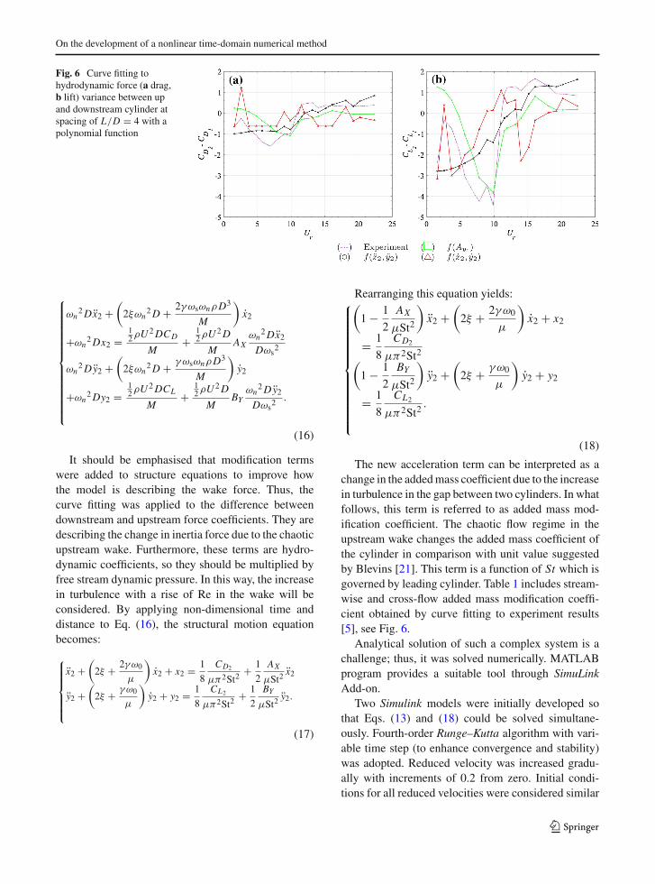
Wake force could be divided into three differentcomponents, mean drag, oscillating lift and drag. Fig-ure 6 displays oscillating drag and lift componentsfor the spacing of L/D = 4. It is possible to exam-ine this difference against several variables and findwhat parameter describes it the best. To avoid alge-braic loops, the modification term should be consid-ered simple so that it is readily transferable to theleft-hand side, which means only a first-order polyno-mial function can be considered. Thus, three differentvariables were examined, leading cylinder cross-flowamplitude, trailing cylinder acceleration and velocity,see Fig. 6. It is evident that upstream displacement pro-vides the best fit, however, as discussedbefore any inputfrom the leading cylinder adds mathematical compli-cations. Trailing cylinder acceleration provides satis-factory results as well.
4.2.1 Added mass modification term
Based on the previous discussion, the modificationterms are defined as functions of acceleration. How-ever, simple expressions of AX X and BY Y would notyield non-dimensional terms after applying dimen-sionless time and distance. Therefore, the modifica-
tion terms should be defined AXX2
Dωs2 and BY
Y2Dωs
2 .
(AX and BY coefficients are functions of spacingto be determined using experimental results.) Hence,motion equations, with dimensionless time and space,become:1
1 It should be strongly emphasised that all structural motionequations hereafter are in the form of Duffing equation. How-ever, to fit the equation in page width, terms related to geometri-cal nonlinearity, x2+αx x23+βx x2y22 and y2+αy y23+βy y2x22,
are omitted. Also, wake force terms 12
ρU2DCL
M
(Y
U
)and
− 12
ρU2DCD
M
(X
U
), due to relative velocity are removed.
123
On the development of a nonlinear time-domain numerical method
Fig. 6 Curve fitting tohydrodynamic force (a drag,b lift) variance between upand downstream cylinder atspacing of L/D = 4 with apolynomial function
⎧⎪⎪⎪⎪⎪⎪⎪⎪⎪⎪⎪⎪⎪⎨⎪⎪⎪⎪⎪⎪⎪⎪⎪⎪⎪⎪⎪⎩
ωn2Dx2 +
(2ξωn
2D + 2γωsωnρD3
M
)x2
+ωn2Dx2 =
12ρU2DCD
M+
12ρU2D
MAX
ωn2Dx2
Dωs2
ωn2Dy2 +
(2ξωn
2D + γωsωnρD3
M
)y2
+ωn2Dy2 =
12ρU2DCL
M+
12ρU2D
MBY
ωn2Dy2
Dωs2 .
(16)
It should be emphasised that modification termswere added to structure equations to improve howthe model is describing the wake force. Thus, thecurve fitting was applied to the difference betweendownstream and upstream force coefficients. They aredescribing the change in inertia force due to the chaoticupstream wake. Furthermore, these terms are hydro-dynamic coefficients, so they should be multiplied byfree stream dynamic pressure. In this way, the increasein turbulence with a rise of Re in the wake will beconsidered. By applying non-dimensional time anddistance to Eq. (16), the structural motion equationbecomes:
⎧⎪⎪⎪⎪⎨⎪⎪⎪⎪⎩
x2 +(2ξ + 2γω0
μ
)x2 + x2 = 1
8
CD2
μπ2St2+ 1
2
AX
μSt2x2
y2 +(2ξ + γω0
μ
)y2 + y2 = 1
8
CL2
μπ2St2+ 1
2
BY
μSt2y2.
(17)
Rearranging this equation yields:⎧⎪⎪⎪⎪⎪⎪⎪⎪⎪⎪⎪⎪⎨⎪⎪⎪⎪⎪⎪⎪⎪⎪⎪⎪⎪⎩
(1 − 1
2
AX
μSt2
)x2 +
(2ξ + 2γω0
μ
)x2 + x2
= 1
8
CD2
μπ2St2(1 − 1
2
BY
μSt2
)y2 +
(2ξ + γω0
μ
)y2 + y2
= 1
8
CL2
μπ2St2.
(18)
The new acceleration term can be interpreted as achange in the addedmass coefficient due to the increasein turbulence in the gap between two cylinders. In whatfollows, this term is referred to as added mass mod-ification coefficient. The chaotic flow regime in theupstream wake changes the added mass coefficient ofthe cylinder in comparison with unit value suggestedby Blevins [21]. This term is a function of St which isgoverned by leading cylinder. Table 1 includes stream-wise and cross-flow added mass modification coeffi-cient obtained by curve fitting to experiment results[5], see Fig. 6.
Analytical solution of such a complex system is achallenge; thus, it was solved numerically. MATLABprogram provides a suitable tool through SimuLinkAdd-on.
Two Simulink models were initially developed sothat Eqs. (13) and (18) could be solved simultane-ously. Fourth-order Runge–Kutta algorithm with vari-able time step (to enhance convergence and stability)was adopted. Reduced velocity was increased gradu-ally with increments of 0.2 from zero. Initial condi-tions for all reduced velocities were considered similar
123

M. Armin et al.
Table 1 Added mass modification coefficients obtained fromcurve fitting for different spacings
L/D AX BY
3.5 0.00007 0.105
4 0.00009 0.1207
5 0.0001 0.1103
8 0.0003 0.0802
10 0.0003 −0.04664
15 0.00008 −0.1486
20 0.00007 −0.1054
at t = 0; CL = CD = 2 and x = y = 0. It shouldbe noted that several initial conditions were tested andit was concluded that this model is not sensitive to theinitial conditions. SimuLink simulations were run for400s for each reduced velocity so that a steady-statesolution was obtained.
Figure 7 presents the simulation results from themodified model for a range of reduced velocitiesagainst experimental results at the corresponding spac-ing. Added mass modification coefficient widens thelock-in range at all spacings. It is established in theliterature that variation of mass ratio has a significanteffect on the width of the lock-in range response. Thus,the effect of the modification term appears to be similarto that of the mass ratio.
Nevertheless, variation in spacing has an insignif-icant effect on the oscillation amplitude which is incontrast with observations from experimental inves-tigations. Additionally, the oscillation amplitude pre-dicted by the model is much higher than the experi-mental results. The difference between the model andexperiment results is not constant at various reducedvelocities; at lower velocities, the model and exper-iment have a better agreement, whereas at intermedi-ately high velocities, themodel yields larger oscillationamplitudes. However, the amplitude predicted by themodel drops below experimental results at very highvelocities. Such a self-limiting characteristic is simi-lar to VIV phenomenon itself. It suggests that a sec-ondary modification term that can damp the amplitudeat medium velocities and increase it at higher velocitiescan resolve this issue. Thus, a the second modificationterm can be defined as a function of the cylinder veloc-ity alike the added mass modification term.
4.2.2 Added damping modification term
The damping term may be considered through a sim-ilar approach previously used. Therefore, it is intro-duced to the motion equation as a force coefficient.Additionally, since this term is reflecting the effect ofthe upstream vortices, it should be a function of theirshedding frequency, and two new modification coeffi-
cients are defined as EXX2
Dωsand FY
Y2Dωs
. (EX and FY
coefficients are functions of spacing to be determinedusing experimental results.) Moreover, the differencebetween upstream and downstream mean drag must beconsidered as well. Therefore, the term C1 is added tothe equation due to shielding effect. So the dimension-less equations of motion become:⎧⎪⎪⎪⎪⎪⎪⎪⎪⎪⎨⎪⎪⎪⎪⎪⎪⎪⎪⎪⎩
(1 − 1
2
AX
μSt2
)x2 +
(2ξ + ω0
μ
(2γ − EX
2St2
))x2 + x2
= 4a(CD2 + C1
) + 2πaCL2
y2Ur(
1 − 1
2
BY
μSt2
)y2 +
(2ξ + ω0
μ
(γ − FY
2St2
))y2 + y2
= aCL2 − 8πaCD2
y2Ur
.
(19)
This equation includes geometrical nonlinearity
term as well
(2πaCL2
y2Ur
, 8πaCD2
y2Ur
). These new
constants (EX , FY ,C1) should be determined throughan optimisation process in such a way that the differ-ence between experimental results and model simula-tion becomes minimum.
4.2.3 Optimisation
The objective of the optimisation is to determineEX , FY and C1 so that the difference between math-ematical model simulation and experimental resultsbecomesminimum.Theoptimisation function [Eq. (20)]was determined in such a way that the accumulativeerror between the experiment and the model in cross-flow direction is minimised. The error function waslimited to the transverse direction, firstly for the sakeof simplicity and secondly, it was observed by Srinilet al. [31] that stream-wise simulation is heavily influ-enced by cross-flow results, and hence, every changein cross-flow model could significantly alter the simu-lation in either direction, while changes in stream-wisedirection have negligible effect on the predicted ampli-tude. Therefore, optimisation in cross-flow motion is
123

On the development of a nonlinear time-domain numerical method
Fig. 7 Experimental response amplitude versus mathematical model simulation at various reduced velocity and spacings. a, b L/D =3.5, c, d L/D = 4, e, f L/D = 5, g, h L/D = 8, i, j L/D = 10, k, l L/D = 15, m, n L/D = 20
Table 2 Options and their designated values for optimisation
Option Value
Maximum number of function evaluations 1e6
Termination tolerance on variables 1e−6
Termination tolerance on the function value 1e−4
considered sufficient.
e =∑|AY2 − y2|
n(20)
fminsearch command in MATLAB was used for opti-misation. This command can calculate the local mini-mum of a discontinuous function with multi-variablesusing the derivative-free method. The algorithm usedfor fminsearch isNelder–Mead simplex algorithm [36].No constraint was set for the error function or any of thevariables. Also, fminsearch command requires no con-straint for optimisation function. Moreover, the initialguess for (EX , FY ,C1) was (0, 0, 0) for initial spac-ing of L/D = 3.5, and then, optimisation results fromsmaller spacings were used as the initial guess for con-secutive spacings. Options chosen for optimisation canbe seen in Table 2. It should be noted that fminsearchterminates optimisation process when conditional tol-erances on variables and function value are satisfiedsimultaneously, see Table 2.
The result of optimisation can be seen in Table 3with the corresponding spacing. Figure 8 demonstratessimulation results from Eq. (19) using Table 3 values.
It can be observed that the mathematical model hasa good agreement with experimental data in cross-flowdirection; however, their agreement with the stream-wise response is relatively poor. Moreover, if the capa-
Table 3 Optimisation output for three modification parametersof EX , FY and C1
L/D EX FY C1
3.5 0.7042 −0.1598 −31.0758
4 0.5947 −0.1788 −29.444
5 0.6152 −0.1878 −30.5058
8 0.2066 −0.2980 −26.8924
10 0.2398 −0.4318 −18.8942
15 0.0933 −0.4552 −17.2843
20 0.092 −0.4191 −14.0297
bilities of the model in simulation of downstream fluid-induced vibration (FIV) response are to be evaluatedby its ability to accurately simulate four parameters oflock-in range width, lock-in onsets velocity, velocitiesat which maximum amplitude occurs and its magni-tude, following observations can be made, see Fig. 8:
– Velocity onset of lock-in range is predicted cor-rectly for both cylinders.
– Lock-in range width is simulated successfully forboth cylinders. However, it is less accurate for thetrailing cylinder in very large spacings.
– Reduced velocity at which maximum amplitudeoccurs is predicted accurately for both cylindersat all spacings.
– Oscillation amplitude at a given reduced velocity issimulated more accurately compared to the exist-ing mathematical models for an isolated cylinder.Although it is evident that themodel under-predictsthe results, nevertheless, the error is less than that ofexisting models in the literature for a single cylin-der.
123

M. Armin et al.
Fig. 8 Experimental response amplitude versus fullymodifiedmathematical model simulation at various reduced velocity and spacings.a, b L/D = 3.5, c, d L/D = 4, e, f L/D = 5, g, h L/D = 8, i, j L/D = 10, k, l L/D = 15, m, n L/D = 20
Fig. 9 Experimental VIV response amplitude versus fully modified mathematical model simulation at various reduced velocity andspacings. a, b L/D = 3.5, c, d L/D = 4, e, f L/D = 5, g, h L/D = 8, i, j L/D = 10, k, l L/D = 15, m, n L/D = 20
– The first peak in the cross-flow response of thetrailing cylinder is captured by the model as well(Fig. 8b, c, f). However, it disappears as the spacinggrows large.
– The reduction of amplitude due to increase in spac-ing can be captured by the model successfully.
Figure 9 includes trailing cylinder response whichconsists of VIV motion and displacement induced byupstreamwake interference.Moreover, Armin et al. [5]observed that structural motion due to VIV and WIVexcitation mechanisms can be separated based on theirfrequency. They concluded that the motion related toirregular collisions of the upstream vortices has higherfrequency. Therefore, if the irregular motion with thehigher frequency was to be eliminated (for more infor-mation on separation procedure of high-frequency fromlow-frequencymotions please, seeArmin et al. [5]), themodel simulation could be appreciated more. Figure 9depicts a comparison between the model results andexperimental result with the high-frequency amplitude
removed. It is clear that the under-prediction problemin simulation results is no longer an issue. Moreover,simulation in the stream-wise direction appears moresuccessful. Although it fails to capture the maximumamplitude value in this direction, the overall behaviourof the cylinder is captured in all spacings.
As mentioned in the previous section, the cross-flow model has a significant effect on the stream-wiseresponse. Hence, the large pick in stream-wise simula-tion at approximately Ur = 6 at small spacings occursdue to existence of a peak in cross-flow response atthe corresponding reduced velocity even though it hasno corresponding peak in the experiment results. It isclear that this peak disappears at large spacings wherethe cross-flow response peak fades.
Universal functions that can determine themodifica-tion coefficients (AX , BY , EX , FY and C1) at differentspacings, without depending on experimental results,are necessary. An attempt to develop such functionswith the space between the two cylinders as their vari-
123

On the development of a nonlinear time-domain numerical method
ables is presented in “Appendix.” These functions areobtained through a series of curve fitting to the valuesgiven in Tables 1 and 3 .
5 Conclusion
The well-received concept of a coupled system of awake oscillator and a structural motion equation wasemployed to develop a time-domain model for simula-tion of interference between two cylinders in tandem.It was assumed that cylinders were rigid and flexiblymounted with identical structural stiffness and massratios in cross-flow and stream-wise directions. Hydro-dynamic coefficients for both cylinders were consid-ered to be equal for the sake of simplicity and compen-sating for the lack of experimental measurements forthe trailing cylinder hydrodynamic coefficients.
Themodelwas developedbasedon a coupled systemof a van der Pol wake oscillator and a Duffing equation.Duffing equation was considered to describe the struc-tural response of the cylinders in both directions, and itis capable of capturing the structural nonlinearity of thesystem. Van der Pol wake oscillator is well received inthe literature as it can capture the self-exciting and self-limiting nature of VIV. The wake oscillator was cou-pled to the structural motion through a linear functionof structural acceleration. The excitation term in Duff-ing equation was the wake force which was obtainedfrom a van der Pol equation.
Furthermore, the excitation term of trailing cylin-der was modified to consider the buffeting impact ofthe vortices in upstream wake. Any input from theupstream cylinder was avoided, and two modificationterms were added to adjust the added mass coefficientand added fluid damping as functions of Strouhal num-ber so that the effect of upstreamwake instability couldbe incorporated in the model.
The hydrodynamic force exerted on each cylinderwas calculated from experimental data through a sim-ple motion equation for a mass–spring and dampersystem. Since the model simulated upstream cylin-der behaviour with a good agreement, the differ-ence betweenupstreamanddownstreamhydrodynamicforces was calculated to determine the additional forcedue to wake interference. Functions of upstream dis-placement, downstream acceleration and velocity werefitted to these values. It was concluded that trailingcylinder acceleration governs this extra force. Two
added mass modification coefficients were defined as
AXX2
Dωs2 and BY
Y2Dωs
2 , and a linear equation was
fitted to upstream and downstream wake force vari-ance. These modification coefficients were consideredas forces in Duffing oscillator equations and were mul-tiplied by dynamic pressure of the free stream. AX andBY were determined by curve fitting to the variance.
It was observed from the simulation results obtainedfrom the newmodel that predictedmaximumamplitudeis significantly higher than that from the experiment.It was concluded that this discrepancy was due to theincrease in damping caused by the turbulent flow inthe wake. The damping was adjusted by a secondary
force modification coefficient as EXX2
Dωsand FY
Y2Dωs
which was multiplied by dynamic pressure of the freestream as well and added to the right-hand side of theDuffing equation. EX and FY constants were derivedthrough optimisation through which the error betweenexperimental and simulation results was minimised. Itshould be mentioned that optimisation was carried outby fminsearch command in MATLAB with no con-straint on the function value or any of the variables.
Based on the performance of themodification coeffi-cients, it was concluded that wake interference reducesthe addedmass coefficient and increases viscous damp-ing (added damping coefficient).
The final model was capable of:
– Predicting upstream and downstream lock-in onsetvelocity
– Simulating the lock-in range width for both cylin-ders
– Predicting the reduced velocity at which maximumamplitude occurs for both cylinders at all spacings
– Predicting the oscillation amplitude at a givenreduced velocity more accurately compared to theexisting mathematical models for an isolated cylin-der.
Energy transfer between fluid and structure is anotherimportant aspect of such investigations that will beaddressed in the future by investigating added massand other hydrodynamic coefficients.
Acknowledgements Authors want to express their apprecia-tion towards Engineering Faculty of theUniversity of Strathclydewho funded this research. They also would like to thank the staff
123
M. Armin et al.
of the Kelvin Hydrodynamics Laboratory who shared their expe-rience with them and provided support during this study.
Declaration
Conflict of interest The authors declare that they have no con-flict of interest
Open Access This article is licensed under a Creative Com-mons Attribution 4.0 International License, which permits use,sharing, adaptation, distribution and reproduction in anymediumor format, as long as you give appropriate credit to the originalauthor(s) and the source, provide a link to the Creative Com-mons licence, and indicate if changes were made. The images orother third partymaterial in this article are included in the article’sCreative Commons licence, unless indicated otherwise in a creditline to thematerial. If material is not included in the article’s Cre-ative Commons licence and your intended use is not permitted bystatutory regulation or exceeds the permitted use, you will needto obtain permission directly from the copyright holder. To viewa copy of this licence, visit http://creativecommons.org/licenses/by/4.0/.
Appendix
At this stage, the simulation has been compared againstexperiment at seven spacings and it is possible to intro-duce universal coefficients for added mass and damp-ing which can evaluate them at different spacings in theform of Eq. (21).
⎧⎪⎪⎪⎪⎪⎪⎨⎪⎪⎪⎪⎪⎪⎩
AX = f (L/D)
BY = f (L/D)
EX = f (L/D)
FY = f (L/D)
C1 = f (L/D)
(21)
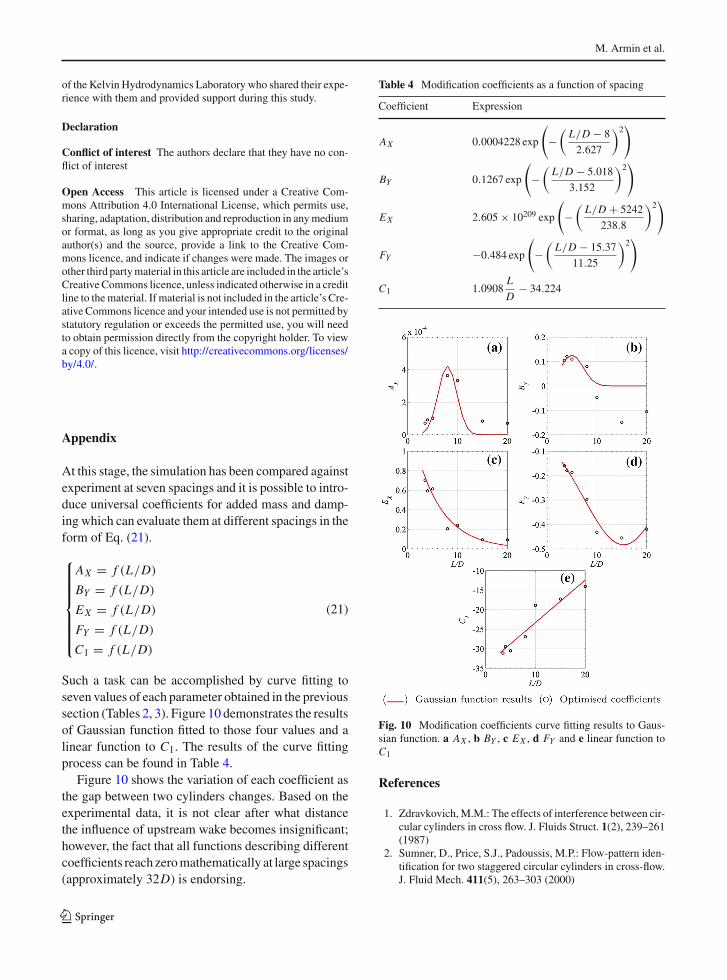
Such a task can be accomplished by curve fitting toseven values of each parameter obtained in the previoussection (Tables 2, 3). Figure 10 demonstrates the resultsof Gaussian function fitted to those four values and alinear function to C1. The results of the curve fittingprocess can be found in Table 4.
Figure 10 shows the variation of each coefficient asthe gap between two cylinders changes. Based on theexperimental data, it is not clear after what distancethe influence of upstream wake becomes insignificant;however, the fact that all functions describing differentcoefficients reach zeromathematically at large spacings(approximately 32D) is endorsing.
Table 4 Modification coefficients as a function of spacing
Coefficient Expression
AX 0.0004228 exp
(−
(L/D − 8
2.627
)2)
BY 0.1267 exp
(−
(L/D − 5.018
3.152
)2)
EX 2.605 × 10209 exp
(−
(L/D + 5242
238.8
)2)
FY −0.484 exp
(−
(L/D − 15.37
11.25
)2)
C1 1.0908L
D− 34.224
Fig. 10 Modification coefficients curve fitting results to Gaus-sian function. a AX , b BY , c EX , d FY and e linear function toC1
References
1. Zdravkovich,M.M.: The effects of interference between cir-cular cylinders in cross flow. J. Fluids Struct. 1(2), 239–261(1987)
2. Sumner, D., Price, S.J., Padoussis, M.P.: Flow-pattern iden-tification for two staggered circular cylinders in cross-flow.J. Fluid Mech. 411(5), 263–303 (2000)
123
On the development of a nonlinear time-domain numerical method
3. Zhang, L.B., Dai, H.L., Abdelkefi, A., Wang, L.: Improvingthe performance of aeroelastic energy harvesters by an inter-ference cylinder. Appl. Phys. Lett. 111(7), 073904 (2017).https://doi.org/10.1063/1.4999765
4. Igarashi, T.: Characteristics of the flow around two circularcylinders arranged in tandem. I. JSME Int. J. Ser. B 24, 323–331 (1981)
5. Armin, M., Khorasanchi, M., Day, S.: Wake interference oftwo identical oscillating cylinders in tandem: an experimen-tal study. Ocean Eng. 166, 311–323 (2018)
6. Kim, S., Alam, M.M., Sakamoto, H., Zhou, Y.: Flow-induced vibrations of two circular cylinders in tandemarrangement. Part 1: characteristics of vibration. J. WindEng. Ind. Aerodyn. 97(5), 304–311 (2009)
7. Huera-Huarte, F.J., Gharib, M.: Vortex- and wake-inducedvibrations of a tandem arrangement of two flexible circularcylinders with far wake interference. J. Fluids Struct. 27(5),824–828 (2011). IUTAMSymposium on Bluff BodyWakesand Vortex-Induced Vibrations (BBVIV-6)
8. Xu, G., Zhou, Y.: Strouhal numbers in the wake of two inlinecylinders. Exp. Fluids 37(2), 248–256 (2004)
9. Sumner, D., Richards, M.D., Akosile, O.O.: Two staggeredcircular cylinders of equal diameter in cross-flow. J. FluidsStruct. 20(2), 255–276 (2005)
10. Kitagawa, T., Ohta, H.: Numerical investigation on flowaround circular cylinders in tandem arrangement at a sub-critical Reynolds number. J. Fluids Struct. 24(5), 680–699(2008)
11. Ishigai, S., Nishikawa, E., Nishimura, K., Cho, K.: Exper-imental study on structure of gas flow in tube banks withtube axes normal to flow: part 1, Karman vortex flow fromtwo tubes at various spacings. Bull. JSME 15(86), 949–956(1972)
12. Assi, G.R.S., Bearman, P.W., Meneghini, J.R.: On the wake-induced vibration of tandem circular cylinders: the vortexinteraction excitation mechanism. J. Fluid Mech. 661(10),365–401 (2010). ISSN 1469-7645
13. Gabbai, R.D., Benaroya, H.: An overview of modeling andexperiments of vortex-induced vibration of circular cylin-ders. J. Sound Vib. 282(3–5), 575–616 (2005)
14. Facchinetti, M.L., de Langre, E., Biolley, F.: Coupling ofstructure and wake oscillators in vortex-induced vibrations.J. Fluids Struct. 19(2), 123–140 (2004)
15. Zanganeh, H.: Modelling and analysis of vortex-inducedvibrations of rigid and flexible cylinders. PhD thesis, Uni-versity of Strathclyde (2015)
16. Thorsen, M.J., Sævik, S., Larsen, C.M.: Non-linear timedomain analysis of cross-flow vortex-induced vibrations.Mar. Struct. 51(Complete), 134–151 (2017). https://doi.org/10.1016/j.marstruc.2016.10.007
17. Bai, X., Qin, W.: Using vortex strength wake oscillator inmodelling of vortex induced vibrations in two degrees offreedom. Eur. J. Mech. B Fluids 48(Complete), 165–173(2014). https://doi.org/10.1016/j.euromechflu.2014.05.002
18. Skop, R.A., Balasubramanian, S.: A new twist on an oldmodel for vortex-excited vibrations. J. Fluids Struct. 11(4),395–412 (1997)
19. Srinil, N., Zanganeh, H.: Modelling of coupled cross-flow/in-line vortex-induced vibrations using double Duffingand van der Pol oscillators. Ocean Eng. 53, 83–97 (2012)
20. Shiau, L.-C.: Wind-induced vibration of two flexible cylin-drical structures. J. Eng. Mech. 115(9), 2089–2098 (1989)
21. Blevins, R.D.: Flow-Induced Vibration. Van Nostrand Rein-hold Co., Inc., New York (1990)
22. Benaroya, H., Gabbai, R.D.: Modelling vortex-inducedfluid–structure interaction. Philos. Trans. R. Soc. Lond. AMath. Phys. Eng. Sci.366(1868), 1231–1274 (2008). https://doi.org/10.1098/rsta.2007.2130
23. Pantazopoulos,M.S.: Vortex-InducedVibration Parameters:Critical Review. American Society of Mechanical Engi-neers, New York (1994)
24. Armin, M.: Interfering of two tandem cylinders undergoingVIV: mathematical modelling and experiments. PhD thesis,University of Strathclyde (2016)
25. Shiau, L.-C., Yang, T.Y., ASCE, M.: Two-cylinder modelfor wind vortex-induced vibration. J. Eng. Mech. 113(5),780–789 (1987)
26. Bearman, P.W.: Vortex shedding from oscillating bluff bod-ies. Annu. Rev. Fluid Mech. 16(1), 195–222 (1984)
27. Okajima, A.: Flows around two tandem circular cylinders atvery high Reynolds numbers. Bull. JSME 22(166), 504–511(1979)
28. Tsutsui, T.: Experimental study on the instantaneous fluidforce acting on two circular cylinders closely arranged intandem. J. Wind Eng. Ind. Aerodyn. 109, 46–54 (2012)
29. Vandiver, J.K., Jong, J.-Y.: The relationship between in-lineand cross-flow vortex-induced vibration of cylinders. J. Flu-ids Struct. 1(4), 381–399 (1987)
30. Blevins, R.D., Coughran, C.S.: Experimental investigationof vortex-induced vibration in one and two dimensions withvariable mass, damping, and Reynolds number. J. FluidMech. 131(October), 101202 (2009)
31. Srinil, N., Zanganeh, H., Day, A.: Two-degree-of-freedomVIV of circular cylinder with variable natural frequencyratio: experimental and numerical investigations. OceanEng. 73, 179–194 (2013)
32. Nayfeh, A.H.: Introduction to Perturbation Techniques.Wiley, New York (2011)
33. Jian-Shu, F., Zhuo, F., Xiao-Juan, L., Man-Sheng, R.: Chaossynchronization in two coupled Duffing oscillators. Chin.Phys. Lett. 18(11), 1438 (2001)
34. Paul Raj, S., Rajasekar, S.: Migration control in two coupledduffing oscillators. Phys. Rev. E 55, 6237–6240 (1997)
35. Vandiver, J.K.: Drag coefficients of long flexible cylinders.In: Offshore Technology Conference (1983)
36. Lagarias, J.C., Reeds, J.A.,Wright,M.H.,Wright, P.E.: Con-vergence properties of the Nelder–Mead simplex method inlow dimensions. SIAM J. Optim. 9(1), 112–147 (1998)
Publisher’s Note Springer Nature remains neutral with regardto jurisdictional claims in published maps and institutional affil-iations.
123